EP0893043A1 - Ploughing apparatus comprising a plurality of disc gangs rotating around the same axis - Google Patents
Ploughing apparatus comprising a plurality of disc gangs rotating around the same axis Download PDFInfo
- Publication number
- EP0893043A1 EP0893043A1 EP98401859A EP98401859A EP0893043A1 EP 0893043 A1 EP0893043 A1 EP 0893043A1 EP 98401859 A EP98401859 A EP 98401859A EP 98401859 A EP98401859 A EP 98401859A EP 0893043 A1 EP0893043 A1 EP 0893043A1
- Authority
- EP
- European Patent Office
- Prior art keywords
- discs
- plowing
- train
- disc
- trains
- Prior art date
- Legal status (The legal status is an assumption and is not a legal conclusion. Google has not performed a legal analysis and makes no representation as to the accuracy of the status listed.)
- Granted
Links
Images


Classifications
-
- A—HUMAN NECESSITIES
- A01—AGRICULTURE; FORESTRY; ANIMAL HUSBANDRY; HUNTING; TRAPPING; FISHING
- A01B—SOIL WORKING IN AGRICULTURE OR FORESTRY; PARTS, DETAILS, OR ACCESSORIES OF AGRICULTURAL MACHINES OR IMPLEMENTS, IN GENERAL
- A01B21/00—Harrows with rotary non-driven tools
- A01B21/08—Harrows with rotary non-driven tools with disc-like tools
Definitions
- the front disc trains may be advantageous to allow the front disc trains to rest freely on the ground by having freedom of movement in the vertical direction by relation to the frame of the plowing machine, while the train (s) rear discs are held in a fixed position by compared to the plowing machine, which imposes a working height on them determined relative to the ground.
- the discs different trains do not have the same number of lobes or flails and / or that their helical mounting on the axis of the different pairs of trains do not happen with the same pace.
- the disc trains may be advantageous to place at the ends of the disc trains, a limited number of discs which are more spaced apart than the other disks on the train. In this case, it is better to space the corresponding discs in this way on the different trains, so that a disc works always between the tracks of two discs from the previous disc train.
- a larger diameter insulated disc that provides complementary tillage while contributing to the stability of the whole by compensating the couples who can tend to make rotate the plowing machine around a vertical axis.
- the plowing machine comprises a double plurality of such trains of discs which are arranged in a substantially symmetrical manner by relative to the axis of movement of the plowing machine, so that the disc trains are arranged in pairs, the pairs located at the front of the craft showing, seen from above, an open V shape towards the front of the machine, while the pair or pairs of discs located at the rear of the craft have, seen from above, a V shape of which the point is directed towards the front of the machine.
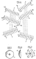
- the disks of these two trains consist of cups whose edges are cut to present a series of lobes as shown in Figures 5 and 6.
- the inclination of the axis of the disc trains with respect to the direction of plowing is a function of the working depth of the discs.
- the disc trains 1 and 2 are mounted floating relative to the spacecraft plowing, i.e. they rest on the ground by their own weight without their height position being imposed on them by the plowing.
- the discs 2 a and 5 has trains 2 and 5 which are located in the vicinity of the axis of the plowing machine have a larger diameter than the diameter of the other discs of the same train, and are offset from each other so that their actions overlap.
- FIG. 4 also shows how the discs situated at the lateral ends of the front disc trains 1, 2 and 5, 6 are provided in their concavity with convex cups 1 d , 2 d , 5 d and 6 d which have the effect of reducing the working capacity of these discs and avoiding the occurrence of projections of soil when the plowing machine works at high speed.
- FIG. 5 shows an elevation view of a disc, the periphery of which is cut in the form of rounded lobes 9, while FIG. 6 shows its section 10 in the form of spherical cap.
- such discs are used for constitute the front trains.
- the larger diameter discs which are located at the ends of the disc trains may have a diameter which is for example 10 to 15% greater than the diameter of current records of the train in question.
- the plowing device according to the invention may comprise the front more than two trains or pairs of disc trains arranged one behind the other, it being understood that a disc must always be find appreciably in the middle of the tracks of two train disks precedes it.
Landscapes
- Life Sciences & Earth Sciences (AREA)
- Engineering & Computer Science (AREA)
- Mechanical Engineering (AREA)
- Soil Sciences (AREA)
- Environmental Sciences (AREA)
- Soil Working Implements (AREA)
- Motorcycle And Bicycle Frame (AREA)
- Turbine Rotor Nozzle Sealing (AREA)
- Crushing And Grinding (AREA)
- Threshing Machine Elements (AREA)
- Holding Or Fastening Of Disk On Rotational Shaft (AREA)
- Toys (AREA)
- Automatic Disk Changers (AREA)
Abstract
Description
La présente invention a pour objet un nouvel engin de labour à disques du type comportant plusieurs trains de disques qui tournent chacun autour d'un même axe.The present invention relates to a new plowing machine with discs of the type comprising several rotating disc chains each around the same axis.
On connaít déjà des engins de labour comportant des trains de disques montés sur un même axe qui sont mis en rotation, indépendamment ou solidairement les uns des autres, lorsqu'ils sont déplacés dans le sens du labour en prenant appui sur le sol, en même temps qu'ils déplacent ou retournent la terre.We already know plowing machines with trains of discs mounted on the same axis which are rotated, independently or jointly of each other, when they are moved in the direction of plowing while resting on the ground, at the same time they move or turn the earth.
On connaít notamment par le brevet français REDARES No 2 666 484 un engin de déchaumage comportant deux rangées parallèles inclinées de disques en forme de calottes sphériques situées à l'avant ainsi qu'une troisième rangée de disques de même forme située à l'arrière de l'engin en étant inclinée dans une direction opposée à celle des deux premières rangées.Are known in particular from French patent REDARES No. 2,666,484 a machine of stubble comprising two parallel inclined rows of shaped discs spherical cap at the front and a third row of the same shape of discs situated at the rear of the machine by being inclined in a direction opposite to that of the first two rows.
Un tel engin permet de hacher et de mélanger le chaume à la terre sur une faible profondeur avec les deux rangées de disques concaves situées à l'avant, tandis que la rangée de disques concaves de plus grand diamètre située à l'arrière assure l'enfouissement du chaume dans le sol.Such a device makes it possible to chop and mix thatch with earth to a shallow depth with the two rows of discs concave located at the front, while the row of concave discs of larger diameter located at the back ensures the burial of thatch in the ground.
De par sa structure et sa destination (broyage et enfouissement du chaume) un tel engin ne peut pas être considéré comme un véritable engin de labour qui doit travailler le sol sur une hauteur plus importante, de manière homogène, en évitant la formation d'une surface plane et continue qui délimite la partie superficielle du sol qui est labourée de la partie du sol plus profonde qui ne l'est pas.Due to its structure and its destination (crushing and burial of thatch) such a machine cannot be considered as a real plowing machine that has to work the soil over a height more consistently, avoiding the formation of a flat and continuous surface which delimits the surface part of the ground which is plowed from the deeper part of the soil which is not.
De tels engins présentent en général l'inconvénient de créer aux extrémités des rangs de disques des accumulations ou des manques de terre dus au fait que lors du labour, cette dernière est déplacée latéralement par rapport à l'axe de l'engin.Such devices generally have the disadvantage of creating at the ends of the rows of discs accumulations or shortages of earth due to the fact that during plowing, the latter is displaced laterally with respect to the axis of the machine.
On connaít aussi des engins de labour qui comportent deux trains de disques disposés côte-à-côte mais qui présentent l'inconvénient de mal travailler la terre dans la zone située aux extrémités des deux trains de disques qui sont au voisinage l'une de l'autre. We also know plowing machines that have two disc trains arranged side by side but presenting the disadvantage of poorly working the soil in the area located ends of the two sets of discs which are in the vicinity one of the other.
On connaít également différents types de disques destinés à être montés sur des engins de labour qui ont sensiblement la forme d'une calotte sphérique et dont la périphérie peut présenter une série d'encoches peu profondes, de lobes convexes ou d'encoches profondes qui donnent au disque l'allure d'une hélice multipale.We also know different types of discs intended for be mounted on plowing machines which have substantially the shape a spherical cap and the periphery of which may have a series shallow notches, convex lobes or deep notches which give the disc the appearance of a multi-blade propeller.
La présente invention a pour objet un nouvel engin de labour qui, par des moyens simples et efficaces, permet d'éviter ces inconvénients.The present invention relates to a new plowing machine which, by simple and effective means, makes it possible to avoid these disadvantages.
Dans sa forme de réalisation la plus simple, la présente invention a pour objet un engin de labour du type comportant à l'avant au moins deux trains de disques dont les axes parallèles entre eux sont inclinés par rapport à une direction perpendiculaire à la direction d'avancement de l'engin de labour, et à l'arrière au moins un train de disques dont l'axe est incliné dans une direction opposée à celle des trains avants, cet engin de labour étant caractérisé par le fait : que les disques des trains avants sont des disques multilobés ; que des disques du ou des trains arrières sont des disques multilobés ou des disques en forme de pales ou de fléaux multiples; que les disques d'un même train sont équidistants ; et que les disques d'un train donné sont situés, vus dans la direction d'avancement de l'engin entre les disques du train qui le précède, de manière à passer entre leurs traces.In its simplest embodiment, the present invention relates to a plowing machine of the type comprising at the front at least two sets of discs whose axes are parallel to each other inclined to a direction perpendicular to the direction advancement of the plowing machine, and at the rear at least one train of discs whose axis is inclined in a direction opposite to that of front undercarriages, this plowing machine being characterized by the fact: the front axle discs are multi-lobed discs; only discs of the rear axle (s) are multi-lobed discs or discs in the form of multiple blades or flails; that the discs of a same train are equidistant; and that the disks of a given train are located, seen in the direction of advancement of the craft between the discs of the train preceding it, so as to pass between their tracks.
Conformément à un mode de réalisation préféré de l'invention, les disques d'un train ont un diamètre d'autant plus grand que ce train est précédé sur l'engin de labour par un nombre de trains de disques plus élevé.In accordance with a preferred embodiment of the invention, the disks of a train have a diameter all the larger as this train is preceded on the plowing machine by a number of disc trains higher.
Conformément à l' invention, il peut être avantageux de permettre aux trains de disques qui sont à l'avant de reposer librement sur le sol en ayant une liberté de mouvement dans le sens vertical par rapport au bâti de l'engin de labour, alors que le ou les trains de disques situés à l'arrière sont maintenus dans une position fixe par rapport à l'engin de labour, ce qui leur impose une hauteur de travail déterminée par rapport au sol.According to the invention, it may be advantageous to allow the front disc trains to rest freely on the ground by having freedom of movement in the vertical direction by relation to the frame of the plowing machine, while the train (s) rear discs are held in a fixed position by compared to the plowing machine, which imposes a working height on them determined relative to the ground.
Selon l'invention, il est avantageux qu'alors que les disques du groupe de trains qui sont situés à l'avant présentent une forme de calotte sphérique dont les bords sont découpés en forme de lobes légèrement arrondis, les disques du train situé à l'arrière de ce groupe sont constitués par des calottes sphériques qui présentent des échancrures importantes de manière à réaliser des disques à pales ou à fléaux multiples.According to the invention, it is advantageous that while the discs of the group of trains which are located at the front have a form of spherical cap whose edges are cut in the shape of lobes slightly rounded, the train disks located at the rear of this group are formed by spherical caps which have large indentations so as to produce discs with blades or multiple plagues.
Il peut être avantageux de placer un disque de plus grand diamètre à l'extrémité arrière d'un train de disques situé à l'avant et à l'extrémité avant du train de disques situé à l'arrière, ce qui permet d'avoir sur une surface labourée plus plane.It may be advantageous to place a larger disc diameter at the rear end of a train of discs located at the front and at the front end of the rear disc train, which allows to have on a more flat plowed surface.
De même, conformément à l' invention, il peut être avantageux de placer à l'extrémité avant d'un train de disques situé à l'avant et à l'extrémité arrière d'un train de disques situé à l'arrière quelques disques de diamètres décroissants pour diminuer l'importance du travail de labour effectué ces extrémités.Similarly, in accordance with the invention, it may be advantageous to place at the front end of a train of discs located at the front and at the rear end of a train of discs located at the rear a few discs of decreasing diameters to reduce the importance of work of plowing performed these ends.
Grâce au fait que conformément à l'invention, les disques d'un train de disques sont situés, vus dans le sens de l'avancement entre deux disques du train de disque qui les précède, (un disque effectuant son travail entre les traces de deux disques qui le précèdent), l'invention permet de réaliser un travail homogène sur toute la surface labourée en évitant la formation de sillons tels que ceux qui se forment habituellement avec les engins de labour de ce type actuellement connus.Thanks to the fact that according to the invention, the discs of a train of discs are located, seen in the direction of advancement between two discs of the train of disc which precedes them, (a disc performing its work between the traces of two discs which the above), the invention makes it possible to carry out a uniform work on the entire plowed area avoiding the formation of furrows such as those that usually form with the plowing machines of this currently known type.
Ce résultat est encore amélioré si les disques d'un même train sont fixés en hélice sur leur axe commun, chaque disque étant décalé par exemple d'un quart ou d'un huitième de tour par rapport à son voisin.This result is further improved if discs of the same train are fixed helically on their common axis, each disc being offset for example by a quarter or an eighth of a turn from his neighbour.
Selon l'invention, est également préférable que les disques des différents trains n'aient pas le même nombre de lobes ou de fléaux et/ou que leur montage en hélice sur l'axe des différentes paires de trains ne se fasse pas avec le même pas.According to the invention, it is also preferable that the discs different trains do not have the same number of lobes or flails and / or that their helical mounting on the axis of the different pairs of trains do not happen with the same pace.
On évite ainsi avec une grande efficacité la formation d'une "semelle", c'est-à-dire d'une interface plans séparant la terre labourée de celle qui ne l'est pas, ce qui est essentiel pour maintenir la terre en bon état de culture.This effectively prevents the formation of a "sole", that is to say of a plane interface separating the earth plowed from that which is not, which is essential to maintain the land in good condition for cultivation.
Conformément à l'invention, il peut être avantageux de placer aux extrémités des trains de disques, un nombre limité de disques qui sont plus espacés entre eux que les autres disques du train. Dans ce cas, il est préférable d'espacer ainsi les disques qui se correspondent sur les différents trains, de manière à ce qu'un disque travaille toujours entre les traces de deux disques du train de disques précédent. According to the invention, it may be advantageous to place at the ends of the disc trains, a limited number of discs which are more spaced apart than the other disks on the train. In this case, it is better to space the corresponding discs in this way on the different trains, so that a disc works always between the tracks of two discs from the previous disc train.
Conformément à l'invention, il est également possible de placer dans l'axe de l'engin de labour, en arrière du premier groupe de trains de disques, un disque isolé de plus grand diamètre qui assure un travail du sol complémentaire tout en participant à la stabilité de l'ensemble en compensant les couples qui peuvent avoir tendance à faire pivoter l'engin de labour autour d'un axe vertical.According to the invention, it is also possible to place in the axis of the plowing machine, behind the first group of disc trains, a larger diameter insulated disc that provides complementary tillage while contributing to the stability of the whole by compensating the couples who can tend to make rotate the plowing machine around a vertical axis.
Dans une variante, il est possible d'utiliser à cette fin, un disque plat agissant comme coutre tournant qui stabilise et maintient l'engin de labour dans sa direction d'avancement ou encore un soc de charrue.In a variant, it is possible to use for this purpose, a flat disc acting as a rotating coulter which stabilizes and maintains the plowing machine in its direction of advancement or a share of plow.
Selon un autre mode de réalisation de l'invention, au lieu de munir l'engin de labour d'une seule pluralité de trains de disques qui sont disposés les uns derrière les autres tel que cela vient d'être décrit, l'engin de labour comporte une double pluralité de tels trains de disques qui sont disposés d'une manière sensiblement symétrique par rapport à l'axe de déplacement de l'engin de labour, de sorte que les trains de disques soient disposés par paires, les paires situées à l'avant de l'engin présentant, vue de dessus, une forme en V ouvert vers l'avant de l'engin, tandis que la ou les paires de disques situées à l'arrière de l'engin présentent, vue de dessus, une forme en V dont la pointe est dirigée vers l'avant de l'engin.According to another embodiment of the invention, instead of provide the plowing machine with a single plurality of disc trains which are arranged one behind the other as it has just been described, the plowing machine comprises a double plurality of such trains of discs which are arranged in a substantially symmetrical manner by relative to the axis of movement of the plowing machine, so that the disc trains are arranged in pairs, the pairs located at the front of the craft showing, seen from above, an open V shape towards the front of the machine, while the pair or pairs of discs located at the rear of the craft have, seen from above, a V shape of which the point is directed towards the front of the machine.
Dans ce mode de réalisation, il est avantageux que les paires de trains de disques disposés en V, que l'on rencontre successivement lorsque l'on se déplace de l'avant vers l'arrière de l'engin de labour, soient alternativement décalées vers la gauche et vers la droite, pour faire en sorte que le sol soit travaillé de manière satisfaisante au voisinage de l'axe de l'engin de labour.In this embodiment, it is advantageous that the pairs disc trains arranged in a V, which are encountered successively when moving from front to rear of the plowing machine, are alternately shifted to the left and to the right, to ensuring that the soil is worked satisfactorily at vicinity of the axis of the plowing machine.
Dans une variante de ce mode de réalisation, les trains de disques d'une même paire de disques sont décalés l'un par rapport à l'autre dans la direction d'avancement de l'engin de labour.In a variant of this embodiment, the trains of discs of the same pair of discs are offset one with respect to the other in the direction of advancement of the plowing machine.
Cette disposition permet en effet d'éviter que la terre qui est située dans l'axe du labour se trouve constamment entre les extrémités centrales des deux trains de disque d'une même paire.This provision makes it possible to prevent the land which is located in the axis of plowing is constantly between the central ends of two disc trains of the same pair.
Dans le but de mieux faire comprendre l'invention on va en décrire maintenant à titre d'illustration et sans aucun caractère limitatif plusieurs modes de réalisation pris comme exemples et représentés sur le dessin annexé. In order to better understand the invention we will describe now for illustration and without any character limiting several embodiments taken as examples and shown in the accompanying drawing.
Sur ce dessin,
- la figure 1 représente une vue schématique de dessus, d'un premier mode de réalisation d'un engin de labour selon l'invention qui comporte trois trains de disques disposés l'un derrière l'autre avec un coutre tournant de stabilisation.
- la figure 2 représente une vue schématique de dessus d'une variante du mode de réalisation de la figure 1,
- la figure 3 représente une vue de dessus d'un second mode de réalisation d'un engin de labour selon l'invention qui comporte trois paires de trains de disques disposées symétriquement par rapport à l'axe du labour,
- la figure 4 représente une variante du mode de réalisation de la figure 3,
- les figures 5 et 6 sont des vues en élévation et en coupe d'un disque de labour multilobé utilisable selon l'invention,
- la figure 7 représente une vue en élévation d'un autre disque de labour multipales ou multifléaux utilisable selon l'invention et,
- la figure 8 est une vue schématique en perspective représentant comment les disques peuvent être fixés en hélice sur leur axe.
- FIG. 1 represents a schematic top view of a first embodiment of a plowing machine according to the invention which comprises three sets of discs arranged one behind the other with a rotating stabilizing coulter.
- FIG. 2 represents a schematic top view of a variant of the embodiment of FIG. 1,
- FIG. 3 represents a top view of a second embodiment of a plowing machine according to the invention which comprises three pairs of disc trains arranged symmetrically with respect to the plowing axis,
- FIG. 4 represents a variant of the embodiment of FIG. 3,
- FIGS. 5 and 6 are views in elevation and in section of a multi-lobed plowing disc usable according to the invention,
- FIG. 7 represents an elevation view of another multi-blade or multi-blade plowing disc usable according to the invention and,
- Figure 8 is a schematic perspective view showing how the discs can be helically fixed on their axis.
On a représenté sur les figures 1 et 2 un mode de réalisation
de l'invention selon lequel on dispose à la partie avant deux trains de
disques 1 et 2 qui sont inclinés par rapport à une perpendiculaire à la
direction du labour et qui, à la manière connue, travaillent la terre
en la déplaçant vers la gauche comme indiqué schématiquement par les
flèches f. There is shown in Figures 1 and 2 an embodiment of the invention according to which there are at the front part two sets of
Conformément à l'invention, les disques de ces deux trains sont constitués par des coupelles dont les bords sont découpés pour présenter une série de lobes tels que représentés sur les figures 5 et 6.According to the invention, the disks of these two trains consist of cups whose edges are cut to present a series of lobes as shown in Figures 5 and 6.
Conformément à l'invention, on a placé à l'arrière de ces
deux trains de disques un troisième train de disques 3 qui est incliné
en sens opposé et qui travaille en déplaçant la terre vers la droite
comme indiqué par la flèche f.In accordance with the invention, a third train of
Les disques du train 3 peuvent être constitués par des
coupelles dont les bords sont découpés pour former des lobes comme
représenté sur les figures 5 et 6, mais ils sont de préférence découpés
en forme de pales ou des fléaux comme représenté sur la figure 7.The disks of
Selon un mode de réalisation préféré de l'invention, tous les disques d'un train sont solidaires en rotation de l'arbre qui les supporte, les disques étant avantageusement décalés l'un par rapport à l'autre de manière à ce que les différents lobes ou pales d'un train soient disposés le long d'une hélice qui s'enroule autour de l'arbre du train de disque, comme on peut le voir sur la figure 8.According to a preferred embodiment of the invention, all of the discs of a train are integral in rotation with the shaft which supports, the discs being advantageously offset one with respect to the other so that the different lobes or blades of a train are arranged along a propeller which wraps around the shaft of the disc train, as can be seen in Figure 8.
Selon une caractéristique de l'invention, on a représenté par
des traits interrompus sur la figure 1 comment, vus dans la direction
du labour les disques du train 2 sont situés sensiblement au milieu des
traces laissées par les disques du train 1.According to a characteristic of the invention, there is represented by
broken lines in Figure 1 how, seen in the direction
of plowing the discs of
Conformément à l'invention, les disques du train 3 sont
également situés, vus dans la direction du labour, sensiblement au
milieu des traces laissées par les disques du train 2.According to the invention, the disks of
Selon un mode de réalisation préféré de l'invention, on
utilise pour chaque train des disques dont le diamètre est plus grand
que le diamètre des disques du train qui le précède. C'est ainsi que
les disques du train 1 sont de diamètre plus petit que celui des
disques du train 2 lesquels sont aussi d'un diamètre plus petit que les
disques du train 3.According to a preferred embodiment of the invention,
use larger diameter discs for each train
than the diameter of the disks of the train preceding it. Therefore
the disks of
Il est également avantageux que les disques des différents trains n'aient pas le même nombre de lobes ou de fléaux et/ou que le pas des hélices selon lesquelles les disques sont fixés sur leur arbre ne soit pas le même pour les différents trains.It is also advantageous that the discs of the different trains do not have the same number of lobes or plagues and / or as the not propellers according to which the discs are fixed on their shaft is not the same for different trains.
L'inclinaison de l'axe des trains de disques par rapport à la direction du labour est fonction de la profondeur de travail des disques.The inclination of the axis of the disc trains with respect to the direction of plowing is a function of the working depth of the discs.
Selon un mode de réalisation particulier de l'invention, les
trains de disques 1 et 2 sont montés flottants par rapport à l'engin de
labour, c'est-à-dire qu'ils reposent sur le sol par leur propre poids
sans que leur position en hauteur leur soit imposée par l'engin de
labour.According to a particular embodiment of the invention, the
Toutefois pour travailler des sols plats, ces disques peuvent être fixes en hauteur par rapport au châssis qui les supporte.However, for working flat soils, these discs can be fixed in height with respect to the frame which supports them.
On peut également selon l'invention, réaliser les trains de disques avant en solidarisant entre eux las axes de plusieurs groupes de disques, chaque groupe pouvant ainsi se déplacer en hauteur indépendamment des autres par rapport au châssis de l'engin de labour.It is also possible, according to the invention, to make the trains of front discs by joining together the axes of several groups discs, each group being able to move in height independently of the others with respect to the chassis of the plowing machine.
Les trains de disques avants sont dans ce mode de réalisation formés d'une pluralité de petits groupes de disques indépendants les uns des autres qui peuvent se soulever ou s'abaisser par rapport au châssis.The front disc trains are in this embodiment formed of a plurality of small groups of independent discs the each other which can be raised or lowered relative to the frame.
Au contraire, le train de disques 3 est de préférence
maintenu dans une position fixe par rapport à l'engin de labour pour
lui permettre de travailler le sol sur une profondeur prédéterminée qui
lui est imposée.On the contrary, the train of
Dans le mode de réalisation de la figure 1, on a placé dans l'axe de l'engin de labour un coutre tournant 4 constitué par un disque dont la partie inférieure s'engage dans la terre selon la direction du labour pour compenser les forces qui pourraient avoir tendance à dévier l'ensemble des disques vers la droite ou vers la gauche.In the embodiment of Figure 1, we placed in the axis of the plowing machine a rotating coulter 4 constituted by a disc the lower part of which engages in the earth in the direction of the plowing to compensate for forces which might tend to deflect all discs to the right or to the left.
Dans une variante, ce coutre tournant 4 peut être remplacé par un soc.In a variant, this rotary coulter 4 can be replaced by a coulter.
Dans la variante de la figure 2, on retrouve les trains de
disques 1, 2 et 3 disposés de la même manière que sur la figure 1.In the variant of Figure 2, we find the trains of
A la différence de la figure 1, l'engin de labour de la
figure 2 ne comporte pas de coutre tournant 4, mais il possède aux
extrémités droites des trains 1, 2 et 3 des disques 1a, 2a, 3a qui ont
la même forme que les autres disques de chaque train mais qui ont un
diamètre supérieur.Unlike Figure 1, Figure 2 the tilling implement has no rotating coulter 4, but has the straight ends of the
Par contre, comme représenté sur la figure 2, les disques
1b, 1c, et 2b, 2c qui sont situés à l'extrémité avant des deux trains
de disques avant 1 et 2 présentent des diamètres décroissants. Il en
est de même pour les deux disques 3b, 3c de l'extrémité arrière du
train de disque arrière 3.By cons, as shown in Figure 2, the discs 1 b , 1 c , and 2 b , 2 c which are located at the front end of the two sets of
On évite ainsi de créer une surépaisseur de la terre sur la gauche de la surface labourée.This avoids creating an excess thickness of the earth on the left of the plowed area.
On a représenté sur les figures 3 et 4, un second mode de
réalisation de l'invention selon lequel les trains de disques avant et
arrière sont disposés par paires, un train de disques 5 étant
symétrique du train 1 par rapport à l'axe du labour, un train de
disques 6 étant symétrique du train 2 par rapport à l'axe du labour, et
un train de disques 7 étant symétrique du train 3 par rapport à l'axe
de labour.There is shown in Figures 3 and 4, a second mode of
embodiment of the invention according to which the front disc trains and
rear are arranged in pairs, a train of
Conformément à un mode de réalisation préféré de l'invention,
l'extrémité gauche du train de disque 5 situé tout à l'avant est situé
à gauche de l'axe F de l'engin de labour, alors que le train du disque
2 qui est situé en seconde position sur la gauche, a son extrémité
droite située à droite de l'axe de l'engin de labour.In accordance with a preferred embodiment of the invention,
the left end of the
Dans une variante préférée de ce mode de réalisation, les
disques 2a et 5a des trains 2 et 5 qui sont situés au voisinage de
l'axe de l'engin de labour présentent un plus grand diamètre que le
diamètre des autres disques du même train, et se trouvent décalés l'un
par rapport à l'autre pour que leurs actions se recouvrent.In a preferred variant of this embodiment, the
On réalise ainsi un meilleur travail de la terre dans la partie centrale du labour en déplaçant la terre d'abord vers la droite puis vers la gauche, comme représenté par les flèches f et en laissant un sillon central.We thus do a better work of the land in the central part of the plow by moving the earth first to the right then to the left, as represented by the arrows f and leaving a central groove.
Dans ce mode de réalisation préféré, les deux trains de
disques 3 et 7, qui sont situés à l'arrière et qui sont inclinés de
manière opposée à l'inclinaison des disques 1, 2, 5 et 6 disposés à
l'avant, présentent aussi chacun à leur extrémité située au voisinage
de l'axe du labour, un disque 3a, ou 7a, de plus grand diamètre, qui a
pour effet d'améliorer encore le travail de la partie centrale du
labour et de refermer plus efficacement le sillon central qui a été
creusé par les trains de disques 1, 2, 5 et 6, situés à l'avant, tandis
que l'ensemble des disques des trains 3 et 4 ramènent la totalité de la
terre labourée vers le centre du labour comme représenté sur les
flèches f.In this preferred embodiment, the two sets of
Comme décrit au sujet de la figure 2, les extrémités avant des trains de disques avant 1, 5 et 2, 6 peuvent être munies de disques dont le diamètre va en décroissant par rapport aux autres disques de ces trains.As described about Figure 2, the front ends front disc trains 1, 5 and 2, 6 can be fitted with discs whose diameter decreases compared to the other discs of these trains.
Il en est de même pour les disques des extrémités arrière des trains de disques arrière 3 et 7.It is the same for the discs of the rear ends of the rear disc trains 3 and 7.
Dans la variante du mode de réalisation de la figure 3 qui est représentée sur la figure 4, les trains de disques d'une même paire sont décalés l'un par rapport à l'autre dans la direction du labour. In the variant of the embodiment of FIG. 3 which is shown in Figure 4, the disc trains of the same pair are offset from each other in the direction of plowing.
On a en outre représenté sur la figure 4, comment les disques
situés aux extrémités latérales des trains de disques avant 1, 2 et 5,
6 sont munis dans leur concavité de coupelles convexes 1d, 2d, 5d et 6d
qui ont pour effet de réduire la capacité de travail de ces disques et
d'éviter que se produisent des projections de terre lorsque l'engin de
labour travaille à grande vitesse.FIG. 4 also shows how the discs situated at the lateral ends of the front disc trains 1, 2 and 5, 6 are provided in their concavity with
On a représenté sur la figure 5 une vue en élévation d'un
disque dont le pourtour est découpé en forme de lobes arrondis 9,
tandis que l'on a représenté sur la figure 6 sa section 10 en forme de
calotte sphérique.FIG. 5 shows an elevation view of a
disc, the periphery of which is cut in the form of
Selon l'invention, de tels disques sont utilisés pour constituer les trains avants.According to the invention, such discs are used for constitute the front trains.
On a représenté sur la figure 7 un autre modèle de disque également en forme de calotte sphérique mais qui comporte des découpes importantes pour se présenter sous la forme d'un disque comportant une pluralité de pales ou fléaux 11 qui travaillent le sol d'une manière différente des disques présentant des lobes sur leur périphérie.Another model of disc has been represented in FIG. 7. also in the shape of a spherical cap but which has cutouts important to appear in the form of a disc comprising a plurality of blades or flails 11 which work the soil in a manner different from discs with lobes on their periphery.
Conformément à l'invention de tels disques multipales ou multifléaux sont avantageusement utilisés pour les trains arrières de l'engin de labour.According to the invention of such multi-blade discs or multifleels are advantageously used for the rear axles of the plowing machine.
Les disques représentés sur les figures 5, 6 et 7 sont de types connus et ils n'ont été représentés ici que pour mieux faire comprendre les types de disques utilisés selon l'invention.The discs shown in Figures 5, 6 and 7 are of known types and they have only been shown here to do better understand the types of discs used according to the invention.
On a schématiquement représenté sur la figure 8 comment les disques d'un même train sont avantageusement fixés sur leur arbre en étant décalés angulairement, ce qui a pour effet de disposer les lobes ou les fléaux le long de lignes hélicoïdales.FIG. 8 schematically shows how the discs of the same train are advantageously fixed on their shaft in being angularly offset, which has the effect of arranging the lobes or plagues along helical lines.
Selon l'invention, les disques qui constituent les mêmes trains de disques situés à l'avant, peuvent avoir par exemple un diamètre de 610mm alors que les disques qui constituent les trains suivants peuvent avoir par exemple un diamètre de 660mm et que les disques des trains arrières peuvent avoir par exemple un diamètre de 760 ou de 810mm.According to the invention, the discs which constitute the same disc trains located at the front, can have for example a 610mm diameter while the discs that make up the trains following can have for example a diameter of 660mm and that the rear axle discs can have for example a diameter of 760 or 810mm.
A titre indicatif, les disques de plus grand diamètre qui sont situés aux extrémités des trains de disques, peuvent avoir un diamètre qui est par exemple de 10 à 15% supérieur au diamètre des disques courants du train considéré. As an indication, the larger diameter discs which are located at the ends of the disc trains, may have a diameter which is for example 10 to 15% greater than the diameter of current records of the train in question.
Il est bien entendu que les modes de réalisation qui ont été représentés sur le dessin, ne sont donnés qu'à titre d'illustration et sans aucun caractère limitatif du caractère de l'invention.It is understood that the embodiments which have been shown in the drawing, are given for illustration only and without any limiting character of the character of the invention.
De même l'engin de labour selon l'invention peut comporter à l'avant plus de deux trains ou paires de trains de disques disposés l'un derrière l'autre, étant entendu qu'un disque doit toujours se trouver sensiblement au milieu des traces de deux disques du train qui le précède.Similarly, the plowing device according to the invention may comprise the front more than two trains or pairs of disc trains arranged one behind the other, it being understood that a disc must always be find appreciably in the middle of the tracks of two train disks precedes it.
Claims (17)
Priority Applications (5)
| Application Number | Priority Date | Filing Date | Title |
|---|---|---|---|
| ARP990103571A AR019437A1 (en) | 1998-07-21 | 1999-07-21 | LABRANZA TEAM THAT UNDERSTANDS AT LEAST TWO TRAYS OF DISCS THAT ROLL AROUND A SAME AXIS |
| PCT/FR1999/001789 WO2000004755A1 (en) | 1998-07-21 | 1999-07-21 | Ploughing machine comprising several disc gangs rotating about a common axis |
| US09/743,858 US6499543B1 (en) | 1998-07-21 | 1999-07-21 | Tilling implement comprising a plurality of gangs of disks rotating about a common axis |
| CA002337324A CA2337324A1 (en) | 1998-07-21 | 1999-07-21 | Ploughing machine comprising several disc gangs rotating about a common axis |
| AU49146/99A AU758488B2 (en) | 1998-07-21 | 1999-07-21 | Ploughing machine comprising several disc gangs rotating about a common axis |
Applications Claiming Priority (2)
| Application Number | Priority Date | Filing Date | Title |
|---|---|---|---|
| FR9709232 | 1997-07-21 | ||
| FR9709232A FR2766052B1 (en) | 1997-07-21 | 1997-07-21 | LABOR MACHINE COMPRISING SEVERAL DISK TRAINS ROTATING AROUND THE SAME AXIS |
Publications (2)
| Publication Number | Publication Date |
|---|---|
| EP0893043A1 true EP0893043A1 (en) | 1999-01-27 |
| EP0893043B1 EP0893043B1 (en) | 2003-03-05 |
Family
ID=9509430
Family Applications (1)
| Application Number | Title | Priority Date | Filing Date |
|---|---|---|---|
| EP98401859A Expired - Lifetime EP0893043B1 (en) | 1997-07-21 | 1998-07-21 | Ploughing apparatus comprising a plurality of disc gangs rotating around the same axis |
Country Status (5)
| Country | Link |
|---|---|
| EP (1) | EP0893043B1 (en) |
| AT (1) | ATE233469T1 (en) |
| DE (1) | DE69811787T2 (en) |
| ES (1) | ES2192310T3 (en) |
| FR (1) | FR2766052B1 (en) |
Cited By (3)
| Publication number | Priority date | Publication date | Assignee | Title |
|---|---|---|---|---|
| EP2232971A1 (en) * | 2009-03-25 | 2010-09-29 | Jean-Charles Javerlhac | Plough disc and ploughing machine including at least one axle system provided with such disc |
| EP2232970A1 (en) | 2009-03-25 | 2010-09-29 | Jean-Charles Javerlhac | Plough disc and ploughing machine including at least one axle system provided with at least one such disc |
| FR2945179A1 (en) * | 2009-05-07 | 2010-11-12 | Jean Charles Javerlhac | Tilling wheel for use on tilling engine, has convex lobes or concave recesses located at periphery of wheel, where two adjacent lobes or recesses present inverse concavity with respect to median plane of wheel |
Families Citing this family (1)
| Publication number | Priority date | Publication date | Assignee | Title |
|---|---|---|---|---|
| FR2896375B1 (en) † | 2006-01-24 | 2010-03-19 | Michel Evin | SOIL WORKING MACHINE, SUCH AS DECHAUMEUSE |
Citations (9)
| Publication number | Priority date | Publication date | Assignee | Title |
|---|---|---|---|---|
| FR469733A (en) * | 1914-03-17 | 1914-08-07 | Internat Harrow Cultivator Com | Improvements to agricultural implements |
| US1639104A (en) * | 1926-11-06 | 1927-08-16 | Deere & Co | Disk harrow |
| US2178052A (en) * | 1937-12-06 | 1939-10-31 | Int Harvester Co | Disk harrow construction |
| DE976328C (en) * | 1952-02-29 | 1963-06-27 | Hans Straub | Soil cultivation device with discs that rotate on the ground and are staggered one behind the other |
| US3734199A (en) * | 1971-02-08 | 1973-05-22 | Deere & Co | Disk harrow with disk gangs spaced longitudinally and overlapped transversely to form a ridge-free center |
| US4291770A (en) * | 1980-01-16 | 1981-09-29 | Engler Louis C | Levee disc apparatus |
| WO1990013218A1 (en) * | 1989-05-02 | 1990-11-15 | Javerlhac Jean C | Tilling wheel for freely rotatable mounting on an axle fixed to the frame of a plough |
| US5082064A (en) * | 1990-01-24 | 1992-01-21 | Landoll Corporation | Tillage implement having depth adjustable discs |
| FR2666484A1 (en) * | 1990-09-06 | 1992-03-13 | Redares Paul | Disc harrow |
Family Cites Families (4)
| Publication number | Priority date | Publication date | Assignee | Title |
|---|---|---|---|---|
| US2775086A (en) * | 1953-04-02 | 1956-12-25 | David C Vaughn | Plow and diamond-shaped frame therefor |
| GB8503025D0 (en) * | 1985-02-06 | 1985-03-06 | Dowdeswell C V R | Cultivation disc assembly |
| FR2673803B1 (en) * | 1991-03-12 | 1994-08-26 | Fenet Sarl Ste Nouvelle | DISC SPRAYER HAVING A STABILIZATION AND GUIDANCE DEVICE. |
| DE29714699U1 (en) * | 1997-08-16 | 1997-10-23 | Peters Friedrich | Disc harrow |
-
1997
- 1997-07-21 FR FR9709232A patent/FR2766052B1/en not_active Expired - Fee Related
-
1998
- 1998-07-21 EP EP98401859A patent/EP0893043B1/en not_active Expired - Lifetime
- 1998-07-21 ES ES98401859T patent/ES2192310T3/en not_active Expired - Lifetime
- 1998-07-21 DE DE69811787T patent/DE69811787T2/en not_active Expired - Lifetime
- 1998-07-21 AT AT98401859T patent/ATE233469T1/en not_active IP Right Cessation
Patent Citations (9)
| Publication number | Priority date | Publication date | Assignee | Title |
|---|---|---|---|---|
| FR469733A (en) * | 1914-03-17 | 1914-08-07 | Internat Harrow Cultivator Com | Improvements to agricultural implements |
| US1639104A (en) * | 1926-11-06 | 1927-08-16 | Deere & Co | Disk harrow |
| US2178052A (en) * | 1937-12-06 | 1939-10-31 | Int Harvester Co | Disk harrow construction |
| DE976328C (en) * | 1952-02-29 | 1963-06-27 | Hans Straub | Soil cultivation device with discs that rotate on the ground and are staggered one behind the other |
| US3734199A (en) * | 1971-02-08 | 1973-05-22 | Deere & Co | Disk harrow with disk gangs spaced longitudinally and overlapped transversely to form a ridge-free center |
| US4291770A (en) * | 1980-01-16 | 1981-09-29 | Engler Louis C | Levee disc apparatus |
| WO1990013218A1 (en) * | 1989-05-02 | 1990-11-15 | Javerlhac Jean C | Tilling wheel for freely rotatable mounting on an axle fixed to the frame of a plough |
| US5082064A (en) * | 1990-01-24 | 1992-01-21 | Landoll Corporation | Tillage implement having depth adjustable discs |
| FR2666484A1 (en) * | 1990-09-06 | 1992-03-13 | Redares Paul | Disc harrow |
Cited By (4)
| Publication number | Priority date | Publication date | Assignee | Title |
|---|---|---|---|---|
| EP2232971A1 (en) * | 2009-03-25 | 2010-09-29 | Jean-Charles Javerlhac | Plough disc and ploughing machine including at least one axle system provided with such disc |
| EP2232970A1 (en) | 2009-03-25 | 2010-09-29 | Jean-Charles Javerlhac | Plough disc and ploughing machine including at least one axle system provided with at least one such disc |
| FR2943490A1 (en) * | 2009-03-25 | 2010-10-01 | Jean Charles Javerlhac | LABOR DISC AND LABOR DEVICE COMPRISING AT LEAST ONE TRAIN EQUIPPED WITH SUCH A DISK |
| FR2945179A1 (en) * | 2009-05-07 | 2010-11-12 | Jean Charles Javerlhac | Tilling wheel for use on tilling engine, has convex lobes or concave recesses located at periphery of wheel, where two adjacent lobes or recesses present inverse concavity with respect to median plane of wheel |
Also Published As
| Publication number | Publication date |
|---|---|
| ATE233469T1 (en) | 2003-03-15 |
| ES2192310T3 (en) | 2003-10-01 |
| EP0893043B1 (en) | 2003-03-05 |
| DE69811787T2 (en) | 2004-02-12 |
| FR2766052A1 (en) | 1999-01-22 |
| FR2766052B1 (en) | 1999-09-17 |
| DE69811787D1 (en) | 2003-04-10 |
Similar Documents
| Publication | Publication Date | Title |
|---|---|---|
| CA2337324A1 (en) | Ploughing machine comprising several disc gangs rotating about a common axis | |
| EP0893043B1 (en) | Ploughing apparatus comprising a plurality of disc gangs rotating around the same axis | |
| EP1125487A1 (en) | Multipurpose machine for intercultivation of tree or bush plantations such as vineyards or orchards | |
| EP0217720B1 (en) | Agricultural soil-tilling machine with a rotor driven around an oblique axis | |
| EP2232970B1 (en) | Plough disc and ploughing machine including at least one axle system provided with at least one such disc | |
| EP0287487A2 (en) | Soil cultivating machine having a rotary shaft transverse to the direction of travel | |
| EP2268122B1 (en) | Farm machine for destroying plant cover on soil by mechanical removal | |
| EP0071516B1 (en) | Implement for preparing the soil prior to seeding | |
| CA2053302C (en) | Ploughing disc for free mounting in rotation on an axis integral with plough frame | |
| FR2591847A1 (en) | MACHINE FOR WORKING EARTH EQUIPPED WITH THE BACK OF SOIL LEVELING TOOLS. | |
| FR2589667A1 (en) | Ridging plough with inclined rotors | |
| EP1203523B1 (en) | Multi-functional plough implement for seeding | |
| EP0342065A1 (en) | Implement for treating ploughed land | |
| FR2943490A1 (en) | LABOR DISC AND LABOR DEVICE COMPRISING AT LEAST ONE TRAIN EQUIPPED WITH SUCH A DISK | |
| FR2867943A1 (en) | Ground working disk for self-propelled or tractor-drawn ground working machine, has radial blades providing torsion which permits to perform stubble plugging or scarification operation on ground, where disk is mounted on machine | |
| FR2616037A1 (en) | Tine-holding unit for producing rotors of rotary harrows | |
| FR2945179A1 (en) | Tilling wheel for use on tilling engine, has convex lobes or concave recesses located at periphery of wheel, where two adjacent lobes or recesses present inverse concavity with respect to median plane of wheel | |
| FR2862477A1 (en) | Stubble-ploughing device for e.g. preparing ground to sow, includes work module, supplement module and finishing module, where work module comprises of two rows of oblique discs that rotate freely | |
| FR2861532A1 (en) | Soil tilling machine has rear sub-assembly with cutting and lifting blades on carriage with wheels that can be raised for operation and lowered for transport | |
| EP0190777B1 (en) | Digger | |
| EP0417023A1 (en) | Machine for preparing the soil for sowing | |
| FR2687276A1 (en) | Machine for working the ground with built-in seed drill | |
| FR2755343A1 (en) | Agricultural machine for working the soil | |
| FR2943489A1 (en) | Plough disk e.g. lobed disk, for plow, has lobe including hollow part and/or orifice managed in central part between center of disk and boundary lines of lobes, where center of disk is shifted from side of boundary line of disk | |
| FR2723812A1 (en) | Reversible plough for agriculture |
Legal Events
| Date | Code | Title | Description |
|---|---|---|---|
| PUAI | Public reference made under article 153(3) epc to a published international application that has entered the european phase |
Free format text: ORIGINAL CODE: 0009012 |
|
| AK | Designated contracting states |
Kind code of ref document: A1 Designated state(s): AT BE CH CY DE DK ES FI FR GB GR IE IT LI LU MC NL PT SE |
|
| AX | Request for extension of the european patent |
Free format text: AL;LT;LV;MK;RO;SI |
|
| 17P | Request for examination filed |
Effective date: 19990720 |
|
| AKX | Designation fees paid |
Free format text: AT BE CH CY DE DK ES LI |
|
| RBV | Designated contracting states (corrected) |
Designated state(s): AT BE CH CY DE DK ES FI FR GB GR IE IT LI LU MC NL PT SE |
|
| RBV | Designated contracting states (corrected) |
Designated state(s): AT BE DE ES FR GB PT |
|
| 111L | Licence recorded |
Free format text: 20010421 0100 SOCIETE DES ETABLISSEMENTS LOUIS QUIVOGNE |
|
| 17Q | First examination report despatched |
Effective date: 20011213 |
|
| GRAH | Despatch of communication of intention to grant a patent |
Free format text: ORIGINAL CODE: EPIDOS IGRA |
|
| GRAH | Despatch of communication of intention to grant a patent |
Free format text: ORIGINAL CODE: EPIDOS IGRA |
|
| GRAA | (expected) grant |
Free format text: ORIGINAL CODE: 0009210 |
|
| AK | Designated contracting states |
Designated state(s): AT BE DE ES FR GB PT |
|
| PG25 | Lapsed in a contracting state [announced via postgrant information from national office to epo] |
Ref country code: AT Free format text: LAPSE BECAUSE OF FAILURE TO SUBMIT A TRANSLATION OF THE DESCRIPTION OR TO PAY THE FEE WITHIN THE PRESCRIBED TIME-LIMIT Effective date: 20030305 |
|
| REG | Reference to a national code |
Ref country code: GB Ref legal event code: FG4D Free format text: NOT ENGLISH |
|
| REF | Corresponds to: |
Ref document number: 69811787 Country of ref document: DE Date of ref document: 20030410 Kind code of ref document: P |
|
| PG25 | Lapsed in a contracting state [announced via postgrant information from national office to epo] |
Ref country code: PT Free format text: LAPSE BECAUSE OF FAILURE TO SUBMIT A TRANSLATION OF THE DESCRIPTION OR TO PAY THE FEE WITHIN THE PRESCRIBED TIME-LIMIT Effective date: 20030605 |
|
| GBT | Gb: translation of ep patent filed (gb section 77(6)(a)/1977) | ||
| PG25 | Lapsed in a contracting state [announced via postgrant information from national office to epo] |
Ref country code: BE Free format text: LAPSE BECAUSE OF NON-PAYMENT OF DUE FEES Effective date: 20030731 |
|
| REG | Reference to a national code |
Ref country code: ES Ref legal event code: FG2A Ref document number: 2192310 Country of ref document: ES Kind code of ref document: T3 |
|
| PLBE | No opposition filed within time limit |
Free format text: ORIGINAL CODE: 0009261 |
|
| STAA | Information on the status of an ep patent application or granted ep patent |
Free format text: STATUS: NO OPPOSITION FILED WITHIN TIME LIMIT |
|
| BERE | Be: lapsed |
Owner name: *JAVERLHAC JEAN-CHARLES Effective date: 20030731 |
|
| 26N | No opposition filed |
Effective date: 20031208 |
|
| PGFP | Annual fee paid to national office [announced via postgrant information from national office to epo] |
Ref country code: GB Payment date: 20050803 Year of fee payment: 8 |
|
| PG25 | Lapsed in a contracting state [announced via postgrant information from national office to epo] |
Ref country code: GB Free format text: LAPSE BECAUSE OF NON-PAYMENT OF DUE FEES Effective date: 20060721 |
|
| GBPC | Gb: european patent ceased through non-payment of renewal fee |
Effective date: 20060721 |
|
| REG | Reference to a national code |
Ref country code: FR Ref legal event code: PLFP Year of fee payment: 19 |
|
| REG | Reference to a national code |
Ref country code: FR Ref legal event code: PLFP Year of fee payment: 20 |
|
| PGFP | Annual fee paid to national office [announced via postgrant information from national office to epo] |
Ref country code: ES Payment date: 20170802 Year of fee payment: 20 Ref country code: DE Payment date: 20170620 Year of fee payment: 20 Ref country code: FR Payment date: 20170731 Year of fee payment: 20 |
|
| REG | Reference to a national code |
Ref country code: DE Ref legal event code: R071 Ref document number: 69811787 Country of ref document: DE |
|
| REG | Reference to a national code |
Ref country code: ES Ref legal event code: FD2A Effective date: 20200723 |
|
| PG25 | Lapsed in a contracting state [announced via postgrant information from national office to epo] |
Ref country code: ES Free format text: LAPSE BECAUSE OF EXPIRATION OF PROTECTION Effective date: 20180722 |