EP0892908B1 - Mutual induction correction - Google Patents
Mutual induction correction Download PDFInfo
- Publication number
- EP0892908B1 EP0892908B1 EP97908474A EP97908474A EP0892908B1 EP 0892908 B1 EP0892908 B1 EP 0892908B1 EP 97908474 A EP97908474 A EP 97908474A EP 97908474 A EP97908474 A EP 97908474A EP 0892908 B1 EP0892908 B1 EP 0892908B1
- Authority
- EP
- European Patent Office
- Prior art keywords
- coils
- radiator
- coil
- current
- circuitry
- Prior art date
- Legal status (The legal status is an assumption and is not a legal conclusion. Google has not performed a legal analysis and makes no representation as to the accuracy of the status listed.)
- Expired - Lifetime
Links
Images

Classifications
-
- G—PHYSICS
- G01—MEASURING; TESTING
- G01B—MEASURING LENGTH, THICKNESS OR SIMILAR LINEAR DIMENSIONS; MEASURING ANGLES; MEASURING AREAS; MEASURING IRREGULARITIES OF SURFACES OR CONTOURS
- G01B7/00—Measuring arrangements characterised by the use of electric or magnetic techniques
- G01B7/004—Measuring arrangements characterised by the use of electric or magnetic techniques for measuring coordinates of points
-
- A—HUMAN NECESSITIES
- A61—MEDICAL OR VETERINARY SCIENCE; HYGIENE
- A61B—DIAGNOSIS; SURGERY; IDENTIFICATION
- A61B5/00—Measuring for diagnostic purposes; Identification of persons
- A61B5/06—Devices, other than using radiation, for detecting or locating foreign bodies ; determining position of probes within or on the body of the patient
- A61B5/061—Determining position of a probe within the body employing means separate from the probe, e.g. sensing internal probe position employing impedance electrodes on the surface of the body
- A61B5/062—Determining position of a probe within the body employing means separate from the probe, e.g. sensing internal probe position employing impedance electrodes on the surface of the body using magnetic field
-
- G—PHYSICS
- G01—MEASURING; TESTING
- G01V—GEOPHYSICS; GRAVITATIONAL MEASUREMENTS; DETECTING MASSES OR OBJECTS; TAGS
- G01V3/00—Electric or magnetic prospecting or detecting; Measuring magnetic field characteristics of the earth, e.g. declination, deviation
- G01V3/08—Electric or magnetic prospecting or detecting; Measuring magnetic field characteristics of the earth, e.g. declination, deviation operating with magnetic or electric fields produced or modified by objects or geological structures or by detecting devices
Definitions
- the present invention relates generally to apparatus for generating and detecting electromagnetic fields, and specifically to non-contact, electromagnetic methods and devices for tracking the position and orientation of an object.
- Non-contact electromagnetic tracking systems are well known in the art, with a wide range of applications.
- U.S. patent 4,054,881 describes a tracking system using three coils to generate electromagnetic fields in the vicinity of the object.
- the fields generated by these three coils are distinguished from one another by open loop multiplexing of time, frequency or phase.
- the signal currents flowing in three orthogonal sensor coils are used to determine the object's position, based on an iterative method of computation.
- a sensor coil is placed in the catheter and generates signals in response to externally applied magnetic fields.
- the magnetic fields are generated by three radiator coils, fixed to an external reference frame in known, mutually spaced locations.
- the amplitudes of the signals generated in response to each of the radiator coil fields are detected and used to compute the location of the sensor coil.
- Each radiator coil is preferably driven by driver circuitry to generate a field at a known frequency, distinct from that of other radiator coils, so that the signals generated by the sensor coil may be separated by frequency into components corresponding to the different radiator coils.
- PCT patent application number WO 96/05768 which is assigned to the assignee of the present application, describes a system that generates six-dimensional position and orientation information regarding the tip of a catheter.
- This system uses a plurality of non-concentric sensor coils adjacent to a locatable site in the catheter, for example near its distal end and a plurality of radiator coils fixed in an external reference frame. These coils generate signals in response to magnetic fields generated by the radiator coils, which signals allow for the computation of six location and orientation coordinates.
- the radiator coils operate simultaneously at different frequencies, for example at 1000, 2000 and 3000 Hz, respectively.
- European patent application EP-A-0339723 describes a magnetic resonance apparatus having a magnet system for generating a steady magnetic field and an rf coil system for generating gradient fields.
- each coil can be detuned for a given frequency of another coil. Therefore, mutual influencing is avoided.
- each such component is assumed to correspond uniquely to a single radiator coil, in a known position, radiating in a narrow, well-defined frequency band.
- the radiator coils also generate magnetic fields at the frequencies outside the desired bands, for example due to mutual inductance effects. These mutually-induced fields lead to errors in determining the position of the object being tracked.
- narrowed field bandwidth is achieved by eliminating mutual inductance effects among a plurality of coils, which generate magnetic fields at different frequencies.
- the present invention provides apparatus for tracking an object by generating magnetic fields, comprising a plurality of radiator coils; driver circuitry coupled thereto, which drives the coils so as to generate magnetic fields at a plurality of driving frequencies; wherein each of the plurality of radiator coils generates a field substantially only at a single, respective driving frequency; characterised by: circuitry associated with at least one of said plurality of radiator coils, wherein said circuitry generates magnetic fields for substantially eliminating magnetic fields generated by the at least one coil in response to fields generated by the other coils.
- one or more additional shimming coils are adjacent to each of the radiator coils.
- the shimming coils are interwound with windings of the radiator coils.
- the shimming coils of each radiator coil are driven by driver circuitry so as to generate magnetic fields that are substantially equal in amplitude and frequency, and opposite in direction, to magnetic field components induced along the axis of that radiator coil by other radiator coils.
- driver circuitry is associated with each of the coils and generates electrical driver currents therein, wherein for each coil the current comprises a major component at the coil's respective driving frequency, and minor components at other frequencies.
- the minor components are substantially equal in amplitude and frequency and 180° out of phase with currents induced in the coil due to magnetic fields generated by other radiator coils, so as to substantially cancel the effect of the induced currents.
- driver circuitry includes sensing apparatus, which measures the amplitude, frequency and phase of induced currents in a coil.
- the driver circuitry further includes an adaptive current supply, which receives the amplitude, frequency and phase data measured by the sensing apparatus, and generates the out of-phase minor current components to substantially cancel the effect of the induced currents.
- driver circuitry comprises ideal current sources, which function to maintain a constant current in each of the coils at its fixed, respective driving frequency.
- the circuitry for eliminating magnetic fields preferably comprises one or more shimming coils, which are preferably interwound with the at least one of said plurality of radiator coils. Furthermore, the driver circuitry preferably drives one of the one or more shimming coils associated with the at least one of said plurality of radiator coils at the respective driving frequency of another one of said plurality of radiator coils.
- the circuitry for eliminating includes an adaptive current supply, which generates electrical current in the at least one of the plurality of radiator coils at the respective driving frequency of another one of the plurality of radiator coils.
- the circuitry for eliminating further includes a current analyzer, coupled to the adaptive current supply, which current analyzer measures parasitic electrical current flowing in the at least one of the plurality of radiator coils at the respective driving frequency of another one of the plurality of radiator coils, and causes the adaptive current supply to adjust the generated current so as to minimize the parasitic electrical current.
- a current analyzer coupled to the adaptive current supply, which current analyzer measures parasitic electrical current flowing in the at least one of the plurality of radiator coils at the respective driving frequency of another one of the plurality of radiator coils, and causes the adaptive current supply to adjust the generated current so as to minimize the parasitic electrical current.
- the driver circuitry is adapted to maintain a constant current in each of the plurality of radiator coils at the single, respective driving frequency thereof.
- Fig. 1 illustrates schematically a system for tracking a probe 20, such as a catheter for medical use, operative in accordance with preferred embodiment of the present invention.
- the system comprises a plurality of radiator coils 22, 24 and 26. These coils generate respective magnetic fields H 1 , H 2 and H 3 , at respective frequencies ⁇ 1 , ⁇ 2 and ⁇ 3 , in the vicinity of probe 20.
- the probe further includes sensor coils 27, 28 and 29, which generate electrical current signals in response to the magnetic fields, wherein the signals comprise. components at frequencies ⁇ 1 , ⁇ 2 and ⁇ 3 , whose respective amplitudes are dependent on the position and orientation of probe 20.
- the system further comprises driver circuitry 30, 32 and 33, coupled to each of the radiator coils, which drives coils 22, 24 and 26 at respective driving frequencies ⁇ 1 , ⁇ 2 and ⁇ 3 .
- the signals generated by sensor coils 27, 28 and 29 are preferably processed by signal processing circuitry 34 and then used by computer 36 to calculate position and orientation coordinates of probe 20.
- Fig. 1 shows three radiator coils 22, 24 and 26 and three sensor coils 27, 28 and 29 in a probe 20. It will be understood, however, that the present invention is equally applicable to tracking systems comprising two, four or more radiator coils and one, two or more sensor coils. The present invention may be used in tracking other types of objects, as well.
- the signals generated by sensor coils 27, 28 and 29 at frequency ⁇ 1 are proportional to the amplitude of the time derivative of the projection of magnetic flux due to field H 1 at probe 20 along each of the respective axes of the sensor coils.
- the signals generated at frequencies ⁇ 2 and ⁇ 3 are similarly proportional to the projections of H 2 and H 3 . Since the direction and amplitude of the magnetic field due to a single such radiator coil can be calculated easily using methods known in the art, the sensor coil signals due to a single radiator coil may be directly related to the sensor coil's distance from and orientation relative to the radiator coil.
- magnetic field H 1 generated by radiator coil 22 is not limited in space to an immediate vicinity of probe 20, but also has a non-zero amplitude in a vicinity of coils 24 and 26.
- one or more shimming coils 40 are adjacent to radiator coil 24, and preferably interwound therewith.
- Driver circuitry 32 drives coil 24 with current I 2 at the coil's driving frequency ⁇ 2 .
- Circuitry 32 further drives shimming coil 40 with current I 2 (1) at frequency ⁇ 1 , wherein this current causes a magnetic field H 2 (1) to be generated along the axis of coil 24 which is equal in amplitude and 180° out of phase with magnetic field H 12 . Consequently, mutually-induced current I 12 will be substantially canceled out by an equal and opposite current induced due to field H 2 (1) .
- each of coils 22, 24 and 26 will be interwound with at least one shimming coil, driven with appropriate currents and frequencies so as to substantially cancel out mutually-induced currents due to all other coils.
- Fig. 3 illustrates schematically an alternative preferred embodiment of the present invention, wherein driver circuitry 32 is adapted to drive coil 24 so as to substantially cancel mutually induced currents.
- Circuitry 32 comprises system current supply 50, which drives coil 24 at its driving frequency ⁇ 2 , and adaptive current supply 52, which generates current to drive coil 24 at the respective frequencies of coils 22 and 26, ⁇ 1 and ⁇ 3 , with amplitudes and phases determined by current analyzer 54.
- the current analyzer samples the current in coil 24, using methods known in the art, and separates the sampled current into frequency components.
- Analyzer 54 causes adaptive supply 52 to adjust the amplitudes and phases of the generated ⁇ 1 and ⁇ 3 currents so as to minimize the components sensed at frequencies ⁇ 1 and ⁇ 3 in the sampled current from coil 24.
- the generated ⁇ 1 and ⁇ 3 currents are substantially equal in amplitude to and 180° out of phase with the mutually induced currents I 12 and I 32 . It will be understood that coils 22 and 26 are driven by similar adaptive driver circuitry.
- signal processing circuitry 34 and computer 36 function to determine amplitudes and phases of the parasitic signal components generated by sensor coils 27, 28 and 29 due to mutual inductance among the radiator coils, and correct the determination of the position of probe 20 to account for the parasitic components.
- the amplitude and phase of the magnetic field due to each of the coils is found using a harmonic detection method.
- N is the number of sampling points.
- signal sampling is thus synchronized with the magnetic field frequencies. If N is a small number, then the sampling is preferably synchronized with the magnetic field, and may preferably be synchronized to take place at the peak of the periodic magnetic field.
- the signals thus obtained at a frequency ⁇ may be expressed as:
- the signals generated by the j th sensor coil comprise frequency components whose respective amplitudes Uij and Vij, at radiator coil frequency ⁇ i , may be expressed as follows:
- Aij and ⁇ i represent the amplitude and phase, respectively, of the position signal components received from sensor coil 28 (here identified as the j th sensor coil) at frequency ⁇ i due to the magnetic field of the i th radiator coil, disregarding mutual inductance effects.
- Aijk m and ⁇ ik m are the respective amplitudes and phases of the parasitic signal components generated by the j th sensor coil at frequency ⁇ i , due to mutual inductance between the i th and k th radiator coils.
- the signals received from the coil are preferably processed using the method shown in Fig. 4.
- the signals are separated into components Uij and Vij at frequencies ⁇ 1 , ⁇ 2 and ⁇ 3 using methods known in the art, such as harmonic detection.
- the amplitudes of these signals Aij are then determined (62), assuming that mutual inductance effects are insignificant, i.e., that all Aijk m are zero.
- Phases ⁇ i and ⁇ ik m which are dependent only on the radiator coils, are derived by measuring the respective radiator coil phases (64).
- the amplitudes Aij are then used to estimate the position and orientation of coils 27, 28 and 29 (66), as described, for example, in PCT patent application number WO 96/05768.
- the theoretical values of Aijk m are then calculated for the estimated position of the sensor coils (68).
- H ik the parasitic magnetic fields generated due to mutual inductance among the radiator coils
- These parasitic fields are transformed from the coordinate frame of the radiator coils to that of the sensor coils, based on the projections of the parasitic fields along the respective axes of the sensor coils.
- the field projections are used to calculate theoretical amplitudes of parasitic signal components generated by the sensor coils, using the relationship where the three values of A m / ipk are the theoretical signal amplitudes in the radiator coils' frame of reference, and Mjp are the elements of the orientation matrix.
- Various methods may be used to determine the amplitude and direction of the parasitic magnetic fields H ik at the position of the sensor coils.
- mutual inductances among the coils and the resultant magnetic fields are calculated theoretically from geometrical considerations, using methods well known in the art.
- the mutual inductance of a pair of radiator coils is determined by activating the driver circuitry of one of the coils, so as to generate a magnetic field at its driving frequency, and then measuring electrical current flowing in the other coil at this frequency. These measured mutual inductances are then used to calculate the resultant parasitic magnetic fields, as explained above.
Landscapes
- Life Sciences & Earth Sciences (AREA)
- Physics & Mathematics (AREA)
- Engineering & Computer Science (AREA)
- Health & Medical Sciences (AREA)
- General Physics & Mathematics (AREA)
- Remote Sensing (AREA)
- Biophysics (AREA)
- Public Health (AREA)
- Biomedical Technology (AREA)
- Heart & Thoracic Surgery (AREA)
- Medical Informatics (AREA)
- Molecular Biology (AREA)
- Surgery (AREA)
- Animal Behavior & Ethology (AREA)
- General Health & Medical Sciences (AREA)
- Pathology (AREA)
- Veterinary Medicine (AREA)
- Electromagnetism (AREA)
- Human Computer Interaction (AREA)
- Environmental & Geological Engineering (AREA)
- Geology (AREA)
- General Life Sciences & Earth Sciences (AREA)
- Geophysics (AREA)
- Measurement Of Length, Angles, Or The Like Using Electric Or Magnetic Means (AREA)
- Magnetic Resonance Imaging Apparatus (AREA)
Description
- The present invention relates generally to apparatus for generating and detecting electromagnetic fields, and specifically to non-contact, electromagnetic methods and devices for tracking the position and orientation of an object.
- Non-contact electromagnetic tracking systems are well known in the art, with a wide range of applications.
- For example, U.S. patent 4,054,881 describes a tracking system using three coils to generate electromagnetic fields in the vicinity of the object. The fields generated by these three coils are distinguished from one another by open loop multiplexing of time, frequency or phase. The signal currents flowing in three orthogonal sensor coils are used to determine the object's position, based on an iterative method of computation.
- U.S. patent 5,391,199, filed July 20, 1993, which is assigned to the assignee of the present application, describes a system for generating three-dimensional location information regarding a medical probe or catheter. A sensor coil is placed in the catheter and generates signals in response to externally applied magnetic fields. The magnetic fields are generated by three radiator coils, fixed to an external reference frame in known, mutually spaced locations. The amplitudes of the signals generated in response to each of the radiator coil fields are detected and used to compute the location of the sensor coil. Each radiator coil is preferably driven by driver circuitry to generate a field at a known frequency, distinct from that of other radiator coils, so that the signals generated by the sensor coil may be separated by frequency into components corresponding to the different radiator coils.
- PCT patent application number WO 96/05768, which is assigned to the assignee of the present application, describes a system that generates six-dimensional position and orientation information regarding the tip of a catheter. This system uses a plurality of non-concentric sensor coils adjacent to a locatable site in the catheter, for example near its distal end and a plurality of radiator coils fixed in an external reference frame. These coils generate signals in response to magnetic fields generated by the radiator coils, which signals allow for the computation of six location and orientation coordinates. As in the case of the '539 patent application described above, the radiator coils operate simultaneously at different frequencies, for example at 1000, 2000 and 3000 Hz, respectively.
- European patent application EP-A-0339723 describes a magnetic resonance apparatus having a magnet system for generating a steady magnetic field and an rf coil system for generating gradient fields. In the rf coil system, each coil can be detuned for a given frequency of another coil. Therefore, mutual influencing is avoided.
- The above tracking systems rely on separation of position-responsive signals into frequency components, wherein each such component is assumed to correspond uniquely to a single radiator coil, in a known position, radiating in a narrow, well-defined frequency band. In practice, however, the radiator coils also generate magnetic fields at the frequencies outside the desired bands, for example due to mutual inductance effects. These mutually-induced fields lead to errors in determining the position of the object being tracked.
- It is an object of the present invention to provide improved electromagnetic radiator coils and driver circuitry therefor, for use in conjunction with object tracking systems, so as to increase the accuracy of object tracking.
- It is a further object of the present invention to provide magnetic field generator coils and associated driver circuitry that generate fields of having narrow bandwidths in the frequency domain.
- In the present invention, narrowed field bandwidth is achieved by eliminating mutual inductance effects among a plurality of coils, which generate magnetic fields at different frequencies.
- The present invention provides apparatus for tracking an object by generating magnetic fields, comprising a plurality of radiator coils; driver circuitry coupled thereto, which drives the coils so as to generate magnetic fields at a plurality of driving frequencies; wherein each of the plurality of radiator coils generates a field substantially only at a single, respective driving frequency; characterised by: circuitry associated with at least one of said plurality of radiator coils, wherein said circuitry generates magnetic fields for substantially eliminating magnetic fields generated by the at least one coil in response to fields generated by the other coils.
- In some preferred embodiments of the present invention, one or more additional shimming coils are adjacent to each of the radiator coils. Preferably the shimming coils are interwound with windings of the radiator coils. The shimming coils of each radiator coil are driven by driver circuitry so as to generate magnetic fields that are substantially equal in amplitude and frequency, and opposite in direction, to magnetic field components induced along the axis of that radiator coil by other radiator coils.
- In other preferred embodiments of the present invention, driver circuitry is associated with each of the coils and generates electrical driver currents therein, wherein for each coil the current comprises a major component at the coil's respective driving frequency, and minor components at other frequencies. The minor components are substantially equal in amplitude and frequency and 180° out of phase with currents induced in the coil due to magnetic fields generated by other radiator coils, so as to substantially cancel the effect of the induced currents.
- In one such preferred embodiment of the present invention, driver circuitry includes sensing apparatus, which measures the amplitude, frequency and phase of induced currents in a coil. The driver circuitry further includes an adaptive current supply, which receives the amplitude, frequency and phase data measured by the sensing apparatus, and generates the out of-phase minor current components to substantially cancel the effect of the induced currents.
- In still other preferred embodiments of the present invention, driver circuitry comprises ideal current sources, which function to maintain a constant current in each of the coils at its fixed, respective driving frequency.
- The circuitry for eliminating magnetic fields preferably comprises one or more shimming coils, which are preferably interwound with the at least one of said plurality of radiator coils. Furthermore, the driver circuitry preferably drives one of the one or more shimming coils associated with the at least one of said plurality of radiator coils at the respective driving frequency of another one of said plurality of radiator coils.
- Preferably the circuitry for eliminating includes an adaptive current supply, which generates electrical current in the at least one of the plurality of radiator coils at the respective driving frequency of another one of the plurality of radiator coils.
- Preferably the circuitry for eliminating further includes a current analyzer, coupled to the adaptive current supply, which current analyzer measures parasitic electrical current flowing in the at least one of the plurality of radiator coils at the respective driving frequency of another one of the plurality of radiator coils, and causes the adaptive current supply to adjust the generated current so as to minimize the parasitic electrical current.
- Preferably the driver circuitry is adapted to maintain a constant current in each of the plurality of radiator coils at the single, respective driving frequency thereof.
- The present invention will be more fully understood from the following detailed description of the preferred embodiments thereof, taken together with the drawings in which:
- Fig. 1 is a schematic representation of an object tracking system operative in accordance with a preferred embodiment of the present invention;
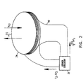
- Fig. 2 is a schematic representation of a radiator coil in accordance with a preferred embodiment of the present invention;
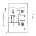
- Fig. 3 is a schematic representation of coil driver circuitry in accordance with another preferred embodiment of the present invention; and
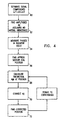
- Fig. 4 is a flow chart illustrating schematically a method of object tracking in accordance with a preferred embodiment of the present invention.
-
- Reference is now made to Fig. 1, which illustrates schematically a system for tracking a
probe 20, such as a catheter for medical use, operative in accordance with preferred embodiment of the present invention. As described in U.S. patent 5,391,199, to Ben-Haim, and in PCT patent application number WO 96/05768, which are assigned to the assignee of the present application, the system comprises a plurality ofradiator coils probe 20. The probe further includessensor coils probe 20. - The system further comprises
driver circuitry coils sensor coils signal processing circuitry 34 and then used bycomputer 36 to calculate position and orientation coordinates ofprobe 20. - For the sake of clarity, Fig. 1 shows three
radiator coils sensor coils probe 20. It will be understood, however, that the present invention is equally applicable to tracking systems comprising two, four or more radiator coils and one, two or more sensor coils. The present invention may be used in tracking other types of objects, as well. - In the absence of mutual inductance effects, the signals generated by
sensor coils probe 20 along each of the respective axes of the sensor coils. The signals generated at frequencies ω2 and ω3 are similarly proportional to the projections of H2 and H3. Since the direction and amplitude of the magnetic field due to a single such radiator coil can be calculated easily using methods known in the art, the sensor coil signals due to a single radiator coil may be directly related to the sensor coil's distance from and orientation relative to the radiator coil. - In practice, however, magnetic field H1 generated by
radiator coil 22 is not limited in space to an immediate vicinity ofprobe 20, but also has a non-zero amplitude in a vicinity ofcoils coil 24 due to current I1 flowing incoil 22 may be expressed as:I coils coil 24 will be:dI - Assuming
coil 24 to have inductance L and zero resistance, the overall voltage in the coil will be: - Since
driver circuitry coils coil 24, having amplitude given by:I - Current I12 flowing in
radiator coil 24 will cause a parasitic magnetic field H12 to be generated at frequency ω1, whose amplitude will be approximately proportional to the ratio M12/L when ω1≈ω2. M12 depends on geometrical factors and on the number of turns in each of the coils. It can be shown (see, for example, J.D. Jackson, Classical Electrodynamics, Second Edition, page 263) that for two coplanar current loops of radius a, mutually spaced by a distance R:
- For
coils coil 24, we may integrate equation (5) to find the mutual inductance of the coils:
- Thus, for example, in a tracking system such as those described in U.S. patent 5,391,199 and in PCT patent application number WO 96/05768, wherein coils 22 and 24 have inner radii of 25 mm and outer radii of approximately 60 mm, and are mutually spaced by 39 cm, it will be observed that I 12 = 0.0025(ω1/ω2)I 1, which could lead to an error of 0.5% when ω1=2ω2. Thus, the signals generated by
sensor coils probe 20. Additional parasitic signal components at frequency ω1 will be introduced by mutual inductance incoil 26 and any other radiator coils. Similarly, sensor coil signals at frequencies ω2 and ω3 will also include parasitic components. - For this reason, in a preferred embodiment of the present invention shown in Fig. 2, one or more shimming coils 40 are adjacent to
radiator coil 24, and preferably interwound therewith.Driver circuitry 32drives coil 24 with current I2 at the coil's driving frequency ω2.Circuitry 32 furtherdrives shimming coil 40 with current I2(1) at frequency ω1, wherein this current causes a magnetic field H2 (1) to be generated along the axis ofcoil 24 which is equal in amplitude and 180° out of phase with magnetic field H12 . Consequently, mutually-induced current I12 will be substantially canceled out by an equal and opposite current induced due to field H2 (1). - Although, for the sake of clarity, Fig. 2 and the foregoing explanation relate only to a single shimming coil, driven at a single frequency, it will be understood that in preferred embodiments of the present invention, each of coils 22, 24 and 26 will be interwound with at least one shimming coil, driven with appropriate currents and frequencies so as to substantially cancel out mutually-induced currents due to all other coils.
- Fig. 3 illustrates schematically an alternative preferred embodiment of the present invention, wherein
driver circuitry 32 is adapted to drivecoil 24 so as to substantially cancel mutually induced currents.Circuitry 32 comprises system current supply 50, which drivescoil 24 at its driving frequency ω2, and adaptivecurrent supply 52, which generates current to drivecoil 24 at the respective frequencies ofcoils current analyzer 54. The current analyzer samples the current incoil 24, using methods known in the art, and separates the sampled current into frequency components.Analyzer 54 causesadaptive supply 52 to adjust the amplitudes and phases of the generated ω1 and ω3 currents so as to minimize the components sensed at frequencies ω1 and ω3 in the sampled current fromcoil 24. Typically the generated ω1 and ω3 currents are substantially equal in amplitude to and 180° out of phase with the mutually induced currents I12 and I32. It will be understood that coils 22 and 26 are driven by similar adaptive driver circuitry. - In other preferred embodiments of the present invention,
signal processing circuitry 34 andcomputer 36 function to determine amplitudes and phases of the parasitic signal components generated bysensor coils probe 20 to account for the parasitic components. - In one such preferred embodiment of the present invention, the amplitude and phase of the magnetic field due to each of the coils is found using a harmonic detection method. In accordance with this method, the signals are sampled so that an integer number of periods of each of the signals are measured, i.e., 2πƒ s /ω = N, where fs is the sampling frequency, and N is the number of sampling points. In this way, signal sampling is thus synchronized with the magnetic field frequencies. If N is a small number, then the sampling is preferably synchronized with the magnetic field, and may preferably be synchronized to take place at the peak of the periodic magnetic field. The signals thus obtained at a frequency ω may be expressed as:

- In the presence of mutual inductance, the signals generated by the jth sensor coil comprise frequency components whose respective amplitudes Uij and Vij, at radiator coil frequency ωi, may be expressed as follows:


- In equations (8) and (9), Aij and i represent the amplitude and phase, respectively, of the position signal components received from sensor coil 28 (here identified as the jth sensor coil) at frequency ωi due to the magnetic field of the ith radiator coil, disregarding mutual inductance effects. Aijkm and ikm are the respective amplitudes and phases of the parasitic signal components generated by the jth sensor coil at frequency ωi, due to mutual inductance between the ith and kth radiator coils.
- In order to correctly determine the position of sensor coils 27, 28 and 29 and
probe 20, the signals received from the coil are preferably processed using the method shown in Fig. 4. First (60) the signals are separated into components Uij and Vij at frequencies ω1, ω2 and ω3 using methods known in the art, such as harmonic detection. The amplitudes of these signals Aij are then determined (62), assuming that mutual inductance effects are insignificant, i.e., that all Aijkm are zero. Phases ϕi and ϕik m, which are dependent only on the radiator coils, are derived by measuring the respective radiator coil phases (64). The amplitudes Aij are then used to estimate the position and orientation ofcoils - The theoretical values of Aijkm are then calculated for the estimated position of the sensor coils (68). To perform this calculation, the parasitic magnetic fields generated due to mutual inductance among the radiator coils, H ik, are determined at the sensor coils' estimated position. These parasitic fields are transformed from the coordinate frame of the radiator coils to that of the sensor coils, based on the projections of the parasitic fields along the respective axes of the sensor coils. The field projections are used to calculate theoretical amplitudes of parasitic signal components generated by the sensor coils, using the relationshipwhere the three values of

A m / ipk are the theoretical signal amplitudes in the radiator coils' frame of reference, and Mjp are the elements of the orientation matrix. - Various methods may be used to determine the amplitude and direction of the parasitic magnetic fields H ik at the position of the sensor coils. In one preferred embodiment of the present invention, mutual inductances among the coils and the resultant magnetic fields are calculated theoretically from geometrical considerations, using methods well known in the art. In an alternative preferred embodiment, the mutual inductance of a pair of radiator coils is determined by activating the driver circuitry of one of the coils, so as to generate a magnetic field at its driving frequency, and then measuring electrical current flowing in the other coil at this frequency. These measured mutual inductances are then used to calculate the resultant parasitic magnetic fields, as explained above.
- Finally, the theoretical Aijkm coefficients are substituted back into equations (8) and (9) to determine corrected values of the nine Aij elements (70), and these values are used to correct the position and orientation coordinates of the probe (72). Steps (68), (70) and (72) are preferably repeated iteratively until the position and orientation coordinates of the probe converge.
- It will be understood that while the above method has been described with reference to a system comprising three radiator coils and three sensor coils, it may equally be applied to other electromagnetic object tracking system, using greater or fewer numbers of coils or antennae,
Claims (9)
- Apparatus for tracking an object by generating magnetic fields, comprising:wherein each of the plurality of radiator coils (22, 24, 26) generates a field substantially only at a single, respective driving frequency; characterised by:a plurality of radiator coils (22, 24, 26);driver circuitry (30, 32, 33) coupled thereto, which drives the coils (22, 24, 26) so as to generate magnetic fields at a plurality of driving frequencies;circuitry (32) associated with at least one of said plurality of radiator coils (24), wherein said circuitry (32) generates magnetic fields for substantially eliminating magnetic fields generated by the at least one coil (24) in response to fields generated by the other coils (22, 26).
- Apparatus in accordance with claim 1, wherein said circuitry for eliminating comprises one or more shimming coils (40).
- Apparatus in accordance with claim 2, wherein the one or more shimming coils (40) are interwound with the at least one of said plurality of radiator coils (24).
- Apparatus in accordance with claim 2 or 3, wherein the driver circuitry (32) further drives one of the one or more shimming coils (40) associated with the at least one of said plurality of radiator coils (24) at the respective frequency of another one of said plurality of radiator coils (22).
- Apparatus in accordance with any preceding claim, wherein the circuitry (32) for eliminating includes an adaptive current supply (52).
- Apparatus in accordance with claim 5, wherein the adaptive current supply (52) generates electrical current in the at least one of said plurality of radiator coils (24) at the respective driving frequency of another one of said plurality of radiator coils (22).
- Apparatus in accordance with claim 5 or 6, wherein the circuitry (32) for eliminating further includes a current analyzer (54) coupled to the adaptive current supply (52).
- Apparatus in accordance with claim 7, wherein the current analyzer (54) measures parasitic electrical current flowing in the at least one of said plurality of radiator coils (24) at the respective driving frequency of another one of said plurality of radiator coils (22), and causes the adaptive current supply (52) to adjust the generated current so as to minimize the parasitic electrical current.
- Apparatus in accordance with any preceding claim, wherein the driver circuitry maintains a constant current in each of the plurality of radiator coils (22, 24, 26) at the single, respective driving frequency thereof.
Applications Claiming Priority (3)
| Application Number | Priority Date | Filing Date | Title |
|---|---|---|---|
| US1408496P | 1996-03-26 | 1996-03-26 | |
| US14084P | 1996-03-26 | ||
| PCT/IL1997/000100 WO1997036143A1 (en) | 1996-03-26 | 1997-03-18 | Mutual induction correction |
Publications (3)
| Publication Number | Publication Date |
|---|---|
| EP0892908A1 EP0892908A1 (en) | 1999-01-27 |
| EP0892908A4 EP0892908A4 (en) | 2000-09-27 |
| EP0892908B1 true EP0892908B1 (en) | 2003-05-14 |
Family
ID=21763453
Family Applications (1)
| Application Number | Title | Priority Date | Filing Date |
|---|---|---|---|
| EP97908474A Expired - Lifetime EP0892908B1 (en) | 1996-03-26 | 1997-03-18 | Mutual induction correction |
Country Status (8)
| Country | Link |
|---|---|
| EP (1) | EP0892908B1 (en) |
| JP (1) | JP4141502B2 (en) |
| AU (1) | AU715167B2 (en) |
| CA (1) | CA2249982C (en) |
| DE (1) | DE69721985T2 (en) |
| ES (1) | ES2200161T3 (en) |
| IL (1) | IL126286A (en) |
| WO (1) | WO1997036143A1 (en) |
Families Citing this family (29)
| Publication number | Priority date | Publication date | Assignee | Title |
|---|---|---|---|---|
| US6147480A (en) * | 1997-10-23 | 2000-11-14 | Biosense, Inc. | Detection of metal disturbance |
| EP1100373B1 (en) | 1998-08-02 | 2008-09-03 | Super Dimension Ltd. | Intrabody navigation system for medical applications |
| IL143909A0 (en) | 1998-12-23 | 2002-04-21 | Jakab Peter D | Magnetic resonance scanner with electromagnetic position and orientation tracking device |
| EP1873545A3 (en) * | 1998-12-23 | 2008-02-13 | Peter D. Jakab | Magnetic resonance scanner with electromagnetic position and orientation tracking device |
| US6498477B1 (en) * | 1999-03-19 | 2002-12-24 | Biosense, Inc. | Mutual crosstalk elimination in medical systems using radiator coils and magnetic fields |
| US9833167B2 (en) | 1999-05-18 | 2017-12-05 | Mediguide Ltd. | Method and system for superimposing virtual anatomical landmarks on an image |
| US6233476B1 (en) | 1999-05-18 | 2001-05-15 | Mediguide Ltd. | Medical positioning system |
| US7778688B2 (en) | 1999-05-18 | 2010-08-17 | MediGuide, Ltd. | System and method for delivering a stent to a selected position within a lumen |
| US9572519B2 (en) | 1999-05-18 | 2017-02-21 | Mediguide Ltd. | Method and apparatus for invasive device tracking using organ timing signal generated from MPS sensors |
| US6484118B1 (en) * | 2000-07-20 | 2002-11-19 | Biosense, Inc. | Electromagnetic position single axis system |
| US7809421B1 (en) * | 2000-07-20 | 2010-10-05 | Biosense, Inc. | Medical system calibration with static metal compensation |
| JP4880264B2 (en) * | 2005-08-24 | 2012-02-22 | オリンパス株式会社 | POSITION DETECTION DEVICE AND MEDICAL DEVICE POSITION DETECTION SYSTEM |
| US8000772B2 (en) * | 2005-10-19 | 2011-08-16 | Biosense Webster, Inc. | Metal immunity in a reverse magnetic system |
| US8798711B2 (en) * | 2006-02-09 | 2014-08-05 | Biosense Webster, Inc. | Shielding of catheter handle |
| US7860553B2 (en) * | 2006-02-09 | 2010-12-28 | Biosense Webster, Inc. | Two-stage calibration of medical probes |
| US8473030B2 (en) * | 2007-01-12 | 2013-06-25 | Medtronic Vascular, Inc. | Vessel position and configuration imaging apparatus and methods |
| US9575140B2 (en) | 2008-04-03 | 2017-02-21 | Covidien Lp | Magnetic interference detection system and method |
| US8473032B2 (en) | 2008-06-03 | 2013-06-25 | Superdimension, Ltd. | Feature-based registration method |
| US8218847B2 (en) | 2008-06-06 | 2012-07-10 | Superdimension, Ltd. | Hybrid registration method |
| US9018935B2 (en) | 2011-09-19 | 2015-04-28 | Mettler-Toledo Safeline Limited | Method for operating a metal detection apparatus and apparatus |
| JP2017527327A (en) | 2014-07-03 | 2017-09-21 | セント・ジュード・メディカル・インターナショナル・ホールディング・エスエーアールエルSt. Jude Medical International Holding S.a,r.l. | Local magnetic field generator |
| US10517505B2 (en) | 2016-10-28 | 2019-12-31 | Covidien Lp | Systems, methods, and computer-readable media for optimizing an electromagnetic navigation system |
| US10792106B2 (en) | 2016-10-28 | 2020-10-06 | Covidien Lp | System for calibrating an electromagnetic navigation system |
| US10751126B2 (en) | 2016-10-28 | 2020-08-25 | Covidien Lp | System and method for generating a map for electromagnetic navigation |
| US10638952B2 (en) | 2016-10-28 | 2020-05-05 | Covidien Lp | Methods, systems, and computer-readable media for calibrating an electromagnetic navigation system |
| US10722311B2 (en) | 2016-10-28 | 2020-07-28 | Covidien Lp | System and method for identifying a location and/or an orientation of an electromagnetic sensor based on a map |
| US10418705B2 (en) | 2016-10-28 | 2019-09-17 | Covidien Lp | Electromagnetic navigation antenna assembly and electromagnetic navigation system including the same |
| US10446931B2 (en) | 2016-10-28 | 2019-10-15 | Covidien Lp | Electromagnetic navigation antenna assembly and electromagnetic navigation system including the same |
| US10615500B2 (en) | 2016-10-28 | 2020-04-07 | Covidien Lp | System and method for designing electromagnetic navigation antenna assemblies |
Family Cites Families (3)
| Publication number | Priority date | Publication date | Assignee | Title |
|---|---|---|---|---|
| NL8801077A (en) * | 1988-04-26 | 1989-11-16 | Philips Nv | MAGNETIC RESONANCE DEVICE WITH DISCONNECTED RF COILS. |
| US5068608A (en) * | 1989-10-30 | 1991-11-26 | Westinghouse Electric Corp. | Multiple coil eddy current probe system and method for determining the length of a discontinuity |
| DE4300529C2 (en) * | 1993-01-12 | 1995-07-13 | Andreas Zierdt | Method and device for determining the spatial arrangement of a direction-sensitive magnetic field sensor |
-
1997
- 1997-03-18 ES ES97908474T patent/ES2200161T3/en not_active Expired - Lifetime
- 1997-03-18 WO PCT/IL1997/000100 patent/WO1997036143A1/en active IP Right Grant
- 1997-03-18 AU AU20414/97A patent/AU715167B2/en not_active Expired
- 1997-03-18 IL IL12628697A patent/IL126286A/en not_active IP Right Cessation
- 1997-03-18 EP EP97908474A patent/EP0892908B1/en not_active Expired - Lifetime
- 1997-03-18 DE DE69721985T patent/DE69721985T2/en not_active Expired - Lifetime
- 1997-03-18 JP JP53420497A patent/JP4141502B2/en not_active Expired - Lifetime
- 1997-03-18 CA CA002249982A patent/CA2249982C/en not_active Expired - Lifetime
Also Published As
| Publication number | Publication date |
|---|---|
| CA2249982C (en) | 2008-10-14 |
| WO1997036143A1 (en) | 1997-10-02 |
| AU715167B2 (en) | 2000-01-20 |
| CA2249982A1 (en) | 1997-10-02 |
| AU2041497A (en) | 1997-10-17 |
| IL126286A (en) | 2001-11-25 |
| EP0892908A4 (en) | 2000-09-27 |
| DE69721985D1 (en) | 2003-06-18 |
| ES2200161T3 (en) | 2004-03-01 |
| EP0892908A1 (en) | 1999-01-27 |
| JP2000508067A (en) | 2000-06-27 |
| IL126286A0 (en) | 1999-05-09 |
| JP4141502B2 (en) | 2008-08-27 |
| DE69721985T2 (en) | 2004-05-19 |
Similar Documents
| Publication | Publication Date | Title |
|---|---|---|
| EP0892908B1 (en) | Mutual induction correction | |
| US6177792B1 (en) | Mutual induction correction for radiator coils of an objects tracking system | |
| US6498477B1 (en) | Mutual crosstalk elimination in medical systems using radiator coils and magnetic fields | |
| US6147480A (en) | Detection of metal disturbance | |
| KR100830853B1 (en) | Metal immune system | |
| EP0581434B1 (en) | Compensation method for an electromagnetic remote position and orientation sensor | |
| USRE43750E1 (en) | Method for navigating a catheter probe | |
| US5646525A (en) | Three dimensional tracking system employing a rotating field | |
| US7292948B2 (en) | Magnetic position and orientation measurement system with eddy current distortion compensation | |
| US5646524A (en) | Three dimensional tracking system employing a rotating field | |
| JP4717341B2 (en) | Dynamic metal compensation | |
| US8013595B2 (en) | AC magnetic tracking system with phase locking | |
| US6404340B1 (en) | Multiple-axis tracking of passive resonant structures | |
| NL8903066A (en) | MAGNETIC RESONANCE DEVICE WITH IMAGE ERROR REDUCTION. |
Legal Events
| Date | Code | Title | Description |
|---|---|---|---|
| PUAI | Public reference made under article 153(3) epc to a published international application that has entered the european phase |
Free format text: ORIGINAL CODE: 0009012 |
|
| 17P | Request for examination filed |
Effective date: 19981022 |
|
| AK | Designated contracting states |
Kind code of ref document: A1 Designated state(s): DE ES FR GB IT NL |
|
| RAP1 | Party data changed (applicant data changed or rights of an application transferred) |
Owner name: BIOSENSE INC. |
|
| A4 | Supplementary search report drawn up and despatched |
Effective date: 20000811 |
|
| AK | Designated contracting states |
Kind code of ref document: A4 Designated state(s): DE ES FR GB IT NL |
|
| 17Q | First examination report despatched |
Effective date: 20020206 |
|
| GRAH | Despatch of communication of intention to grant a patent |
Free format text: ORIGINAL CODE: EPIDOS IGRA |
|
| RIC1 | Information provided on ipc code assigned before grant |
Free format text: 7G 01B 7/14 A, 7G 01B 7/004 B |
|
| RIC1 | Information provided on ipc code assigned before grant |
Free format text: 7G 01B 7/14 A, 7G 01B 7/004 B |
|
| GRAH | Despatch of communication of intention to grant a patent |
Free format text: ORIGINAL CODE: EPIDOS IGRA |
|
| GRAA | (expected) grant |
Free format text: ORIGINAL CODE: 0009210 |
|
| AK | Designated contracting states |
Designated state(s): DE ES FR GB IT NL |
|
| REG | Reference to a national code |
Ref country code: GB Ref legal event code: FG4D |
|
| REF | Corresponds to: |
Ref document number: 69721985 Country of ref document: DE Date of ref document: 20030618 Kind code of ref document: P |
|
| RAP2 | Party data changed (patent owner data changed or rights of a patent transferred) |
Owner name: BIOSENSE, INC. |
|
| NLT2 | Nl: modifications (of names), taken from the european patent patent bulletin |
Owner name: BIOSENSE, INC. |
|
| REG | Reference to a national code |
Ref country code: ES Ref legal event code: FG2A Ref document number: 2200161 Country of ref document: ES Kind code of ref document: T3 |
|
| ET | Fr: translation filed | ||
| PLBE | No opposition filed within time limit |
Free format text: ORIGINAL CODE: 0009261 |
|
| STAA | Information on the status of an ep patent application or granted ep patent |
Free format text: STATUS: NO OPPOSITION FILED WITHIN TIME LIMIT |
|
| 26N | No opposition filed |
Effective date: 20040217 |
|
| REG | Reference to a national code |
Ref country code: FR Ref legal event code: PLFP Year of fee payment: 20 |
|
| PGFP | Annual fee paid to national office [announced via postgrant information from national office to epo] |
Ref country code: DE Payment date: 20160315 Year of fee payment: 20 Ref country code: ES Payment date: 20160211 Year of fee payment: 20 Ref country code: NL Payment date: 20160310 Year of fee payment: 20 |
|
| PGFP | Annual fee paid to national office [announced via postgrant information from national office to epo] |
Ref country code: FR Payment date: 20160208 Year of fee payment: 20 Ref country code: GB Payment date: 20160316 Year of fee payment: 20 |
|
| PGFP | Annual fee paid to national office [announced via postgrant information from national office to epo] |
Ref country code: IT Payment date: 20160324 Year of fee payment: 20 |
|
| REG | Reference to a national code |
Ref country code: DE Ref legal event code: R071 Ref document number: 69721985 Country of ref document: DE |
|
| REG | Reference to a national code |
Ref country code: NL Ref legal event code: MK Effective date: 20170317 |
|
| REG | Reference to a national code |
Ref country code: GB Ref legal event code: PE20 Expiry date: 20170317 |
|
| PG25 | Lapsed in a contracting state [announced via postgrant information from national office to epo] |
Ref country code: GB Free format text: LAPSE BECAUSE OF EXPIRATION OF PROTECTION Effective date: 20170317 |
|
| REG | Reference to a national code |
Ref country code: ES Ref legal event code: FD2A Effective date: 20170626 |
|
| PG25 | Lapsed in a contracting state [announced via postgrant information from national office to epo] |
Ref country code: ES Free format text: LAPSE BECAUSE OF EXPIRATION OF PROTECTION Effective date: 20170319 |