EP0891100A1 - Method and device for coding and decoding data, notably digital images and sequences of digital images - Google Patents
Method and device for coding and decoding data, notably digital images and sequences of digital images Download PDFInfo
- Publication number
- EP0891100A1 EP0891100A1 EP98401708A EP98401708A EP0891100A1 EP 0891100 A1 EP0891100 A1 EP 0891100A1 EP 98401708 A EP98401708 A EP 98401708A EP 98401708 A EP98401708 A EP 98401708A EP 0891100 A1 EP0891100 A1 EP 0891100A1
- Authority
- EP
- European Patent Office
- Prior art keywords
- coded
- block
- blocks
- data
- sub
- Prior art date
- Legal status (The legal status is an assumption and is not a legal conclusion. Google has not performed a legal analysis and makes no representation as to the accuracy of the status listed.)
- Withdrawn
Links
Images


Classifications
-
- H—ELECTRICITY
- H04—ELECTRIC COMMUNICATION TECHNIQUE
- H04N—PICTORIAL COMMUNICATION, e.g. TELEVISION
- H04N19/00—Methods or arrangements for coding, decoding, compressing or decompressing digital video signals
- H04N19/90—Methods or arrangements for coding, decoding, compressing or decompressing digital video signals using coding techniques not provided for in groups H04N19/10-H04N19/85, e.g. fractals
- H04N19/99—Methods or arrangements for coding, decoding, compressing or decompressing digital video signals using coding techniques not provided for in groups H04N19/10-H04N19/85, e.g. fractals involving fractal coding
-
- H—ELECTRICITY
- H04—ELECTRIC COMMUNICATION TECHNIQUE
- H04N—PICTORIAL COMMUNICATION, e.g. TELEVISION
- H04N19/00—Methods or arrangements for coding, decoding, compressing or decompressing digital video signals
- H04N19/50—Methods or arrangements for coding, decoding, compressing or decompressing digital video signals using predictive coding
- H04N19/503—Methods or arrangements for coding, decoding, compressing or decompressing digital video signals using predictive coding involving temporal prediction
-
- H—ELECTRICITY
- H04—ELECTRIC COMMUNICATION TECHNIQUE
- H04N—PICTORIAL COMMUNICATION, e.g. TELEVISION
- H04N19/00—Methods or arrangements for coding, decoding, compressing or decompressing digital video signals
- H04N19/30—Methods or arrangements for coding, decoding, compressing or decompressing digital video signals using hierarchical techniques, e.g. scalability
-
- H—ELECTRICITY
- H04—ELECTRIC COMMUNICATION TECHNIQUE
- H04N—PICTORIAL COMMUNICATION, e.g. TELEVISION
- H04N19/00—Methods or arrangements for coding, decoding, compressing or decompressing digital video signals
- H04N19/60—Methods or arrangements for coding, decoding, compressing or decompressing digital video signals using transform coding
Definitions
- the present invention concerns, in general terms, a method and device for coding data, and a method and device for decoding data.
- Data coding and decoding relates in particular to compressing and decompressing sets of data.
- a set of compressed data can be stored to memory occupying memory space which is small compared with the initial uncompressed set, or can be transmitted more rapidly, or with a lower transmission speed, than the uncompressed initial set.
- a first type of method is the so-called MPEG (Motion Picture Expert Group) coding which consists overall of coding images with respect to one or more other images selected from the sequence, referred to as reference images, and periodically an image with respect to itself.
- MPEG Motion Picture Expert Group
- An image coded with respect to itself referred to as an « intra » image, is divided into blocks, which are coded by discreet cosine transformation (DCT). These images are necessary for refreshing and allow random access in the sequence; however, the degree of compression of these images is low.
- DCT discreet cosine transformation
- An image coded with respect to one or more other images is also divided into blocks.
- Each block is coded by means of an estimation and movement compensation mechanism with respect to a block which needs to be sought in the reference images, and then the error is coded by discreet cosine transformation.
- the « best » block for coding the current block is generally sought in a window of the reference image, in order to reduce the search time which, otherwise, could be too long. However, this type of coding remains fairly slow.
- this type of coding is not suitable for low transmission speeds, of around few tens of kilobits, but is limited to speeds generally greater than 1.5 Megabits per second.
- a second type of image sequence coding consists of coding a current image in the sequence with respect to the previous image.
- the current image is divided into blocks.
- For each block to be coded a single block in a dictionary consisting of the blocks of the previous image is sought, having undergone transformation such as rotation, or symmetry.
- a linear transformation is then calculated between the current block and the reference block.
- the second type of coding entails decoding by iteration of each coded block, which there again requires a relatively long time.
- Progressive coding of the data enables progressive transmission of the coded data.
- an image it is possible to construct, in the process of transmission of the image, an approximate version of the transmitted image.
- the approximate version is constructed from the data already received without waiting until all the data relating to the image have been transmitted.
- the received image is gradually improved as the data are transmitted.
- Progressive transmission enables a user to quickly display the approximate version of the image.
- the user can interrupt the transmission in progress if the approximate version of the image is sufficient or on the contrary if the image is not the one desired.
- JPEG Joint Picture Expert Group
- HJPEG Hierarchic Joint Picture Expert Group
- HJPEG coding is relatively long and complex to implement, since it is based on transformation calculations, in this case discrete cosine transformation. Likewise, the decoding requires calculations of the same complexity and length.
- the present invention aims to remedy the drawbacks of the prior art by providing a method and device for coding data, and the corresponding decoding method and device, having a high degree of data compression, whilst being fast in coding and decoding.
- the invention is situated in the field of coding and decoding with losses of digital image and digital image sequences by blocks.
- the invention is based on the principal of coding each image in sequence as a function of at least one reference image.
- the invention proposes a method of coding a set of data representing physical quantities, the said set being composed of sub-sets, characterised in that it includes, for each of the sub-sets, the steps of:
- the invention proposes a device for coding a set of data representing physical quantities, the said set being composed of sub-sets, characterised in that it has:
- the invention makes it possible to obtain a high degree of compression of the data, which can then be transmitted at a low transmission speed, of around a few tens of kilobits per second, whilst offering good quality of reconstruction of the data.
- the invention affords rapid compression and decompression of the data.
- the invention applies both to cases where both a rapid compression and a rapid decompression of an image sequence is desired, and in a case where only a rapid decompression is desired.
- the method also includes the step of seeking whether the block to be coded can be coded by block matching, and seeking a transformation only if a matching criterion is not satisfied. Coding by block matching requires few bits for storing and/or transmitting the coded block.
- the matching criterion includes a measurement of a first distance between the block to be coded and the source block, which constitutes a simple means of implementing this aspect of the invention.
- the method includes, for each of the sub-sets, the additional steps of:
- the method includes the calculation of a second distance between each zone and a corresponding zone in an adjacent sub-set, the zone criterion consists of comparing this distance with a threshold and, if this distance is less than the threshold, the zone in question is of the first type, and of the second type otherwise.
- the zones of the first type are zones which remain unchanged from one sub-set to the other. These zones are coded by means of another coding method, or are copied from one sub-set to the other, without being coded. Zones which remain unchanged in several sub-sets are coded only once, for the first of the sub-sets in question, and are then copied for the following sub-sets, which is fast and requires few bits for storing and/or transmitting these zones. Decoding is also rapid.
- the zones of the first type are coded by a fixed image coding method.
- the transformation is determined so as to minimise a third distance between the block to be coded and its approximation calculated by applying the transformation to the selected source blocks.
- the calculation of the third distance includes the calculation of a difference, for example the root mean square error, between the values of the data in the block to be coded and the values of its approximation calculated by applying the transformation to the source blocks.
- the transformation is a multilinear approximation, or the transformation is a multilinear approximation combined with a geometric transformation, or again the transformation is a polynomial on the values of the coefficients of the source blocks.
- the type of transformation is chosen according to the coding precision, the coding speed and the desired degree of compression.
- the method includes the calculation of a fourth distance between the block to be coded and the approximation calculated by applying the transformation to the source blocks, the size criterion consists of comparing the fourth distance with a threshold, and, if the fourth distance is greater than the threshold, and if a minimum block size has not been reached, the block in the course of coding is divided into blocks of smaller size.
- the coding device includes means adapted to implement the previously disclosed characteristics.
- the invention also concerns a method of decoding a set of data representing physical quantities, the set being composed of sub-sets which each include coded representations of data blocks, each of the blocks being coded by means of a transformation between source blocks selected in at least one reference sub-set and the block, characterised in that it includes, for each of the blocks of each of the sub-sets to be decoded, the step of applying the transformation to the source blocks in order to decode the block.
- the decoding method includes, for each of the blocks of each of the sub-sets to be decoded, the steps of:
- the block is decoded by copying a matched block determined by block matching. Decoding the block in question is therefore very simple and fast.
- the decoding method includes reading the size and position of the blocks to be decoded, when the blocks are of variable size.
- the invention concerns a method of decoding a set of data representing physical quantities, the set being composed of sub-sets which each include coded representations of zones belonging to a first or a second type of zone, the coded representations of the second type of zone being effected by blocks of data, characterised in that it includes, for each of the blocks of zones of the second type of each of the sub-sets to be decoded, the step of applying the transformation to the source blocks in order to decode the block.
- the invention also concerns a decoding device having means adapted to implement the characteristics previously disclosed. These means are incorporated in:
- the invention proposes a method of coding a set of data representing physical quantities, characterised in that it includes the step of:
- the invention proposes a device for coding a set of data representing physical quantities, characterised in that it has:
- the invention belongs in the field of progressive coding and decoding with losses of data, notably digital images.
- the coding is carried out per block.
- the invention enables rapid compression and decompression of data.
- the invention is more particularly intended for the transmission of compressed data.
- the method also includes the step of transmitting the transformation determined for each data block.
- a search is effected, for each block of data to be coded, as to whether a matching of the block to be coded with one of the source blocks meets a matching criterion.
- the block is then coded by means of a transformation only if the criterion is not satisfied. Coding by block matching is quick and requires few bits. The decoding is also very quick.
- the matching criterion of the matching step consists of a measurement of a first distance between the block to be coded and the source block. This type of criterion is simple to implement.
- a set of data to be coded is constructed at each coding iteration, prior to the actual coding.
- this set is constructed by subtraction of a mean of the set of data representing physical quantities from the said set of data representing physical quantities.
- this set is constructed by subtraction of the set to be coded at the preceding iteration from a set of data reconstructed from the transformations determined at the preceding iteration.
- the set of data to be coded at each iteration is the result of a difference.
- a difference image is generally coded with a greater accuracy than the original image.
- Other preferred characteristics are similar to those previously described.
- the invention proposes a method of decoding a set of coded data representing physical quantities, the set of data being coded by a series of coding sets which each consist of coded representations of data blocks, each block being coded by means of a transformation between source blocks selected from a reference set and the block, characterised in that it includes, for each coding set successively and for each block, the step of applying the transformation to the source blocks in order to decode the block.
- the decoding method also includes, for the first iteration, the addition of a mean to the set resulting from application of the transformation to the source blocks for each of the blocks, and, from the second iteration, the addition of the set resulting from the decoding at the preceding iteration and the set resulting from application of the transformation to the source blocks for each of the blocks.
- the present invention also concerns a data processing device, a communication device, such as computer, printer or facsimile apparatus, including the preceding coding device, or the preceding decoding device.
- a communication device such as computer, printer or facsimile apparatus, including the preceding coding device, or the preceding decoding device.
- the present invention also concerns a storage medium, such as a floppy disk or a CD-ROM.
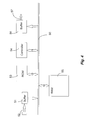
- a data coding device 2 has an input 22 to which is connected a source 1 of uncoded data.
- the source 1 has for example a memory means, such as a random access memory, hard disk, diskette or compact disk, for storing uncoded data, this memory means being associated with a suitable reading means for reading the data therein.
- a means for recording the data in the memory means can also be provided.
- the source 1 can for example be a digital video camera delivering a sequence of images in the case of an image signal or a microphone in the case of a sound signal.
- the source 1 may also be for example a digital photographic camera in the case of a signal representing a fixed image.
- the sequence of image can be coded as a whole, each image being coded as a function of at least one reference image, or each image in the sequence may be coded as a fixed image, independently of the other images in the sequence.
- the sequence can also be coded as a three-dimensional signal (two spatial dimensions and one time dimension), similarly to a fixed image.
- Means 3 using coded data are connected at the output 27 of the coding device 2.
- the user means 3 include for example means for storing coded data, and/or means of transmitting coded data.
- Figure 2 depicts a device 5 for decoding data coded by the device 2.
- Means 4 using coded data are connected at the input 52 of the decoding device 5.
- the means 4 include for example means of storing coded data, and/or means of receiving coded data which are adapted to receive the coded data transmitted by the transmission means 3.
- Means 6 using decoded data are connected at the output 57 of the decoding device 5.
- the user means 6 are for example image display means, or sound restoration means, according to the nature of the data being processed.
- the coding device and the decoding device can be integrated into one and the same digital apparatus, for example a digital video camera, or a digital photographic camera, provided with a display screen.
- the preceding coding device, or the preceding decoding device can be integrated in a data processing device, a communication device, such as computer, printer or facsimile apparatus.
- FIG. 3 One embodiment of a data coding device 2 is depicted in Figure 3 .
- the coding device 2 has a data and address bus 20 to which are connected:
- the coding algorithm can be, totally or partially, memorised in any storage medium capable of cooperating with the controller 24.
- This storage medium is integrated or can be detachably mountable on the coding device.
- the storage medium is a floppy disk, or a CR-ROM.
- FIG. 4 An embodiment of the data decoding device 5 is depicted in Figure 4 .
- the decoding device 5 has a data and address bus 50 to which are connected:
- the decoding algorithm can be, totally or partially, memorised in any storage medium capable of cooperating with the controller 54.
- This storage medium is integrated or can be detachably mountable on the decoding device.
- the storage medium is a floppy disk, or a CR-ROM.
- Figures 5 to 18 more particularly relate to image sequences.
- the invention applies to the coding of a set of data representing physical quantities which is a series of digital images f 1 to f N , where N is an integer.
- Any image f n in the sequence, with n lying between 1 and N, is a grey-level image, having for example 128 x 96 pixels with 256 levels.
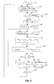
- the algorithm depicted in Figure 5 has steps E1 to E14 which perform the coding of the sequence of digital images. Processing is effected image by image. Overall, an image in the sequence is coded as a function of a reference image.
- Step E1 is an initialisation where the parameter n is initialised to 1, so as to consider first of all the first image in the sequence.
- the following step E2 is a division of the image in question f n into a predetermined number M of blocks A n,1 to A n,M of adjacent pixels.
- the number M of blocks can be predetermined, or can be a parameter set by the user of the algorithm.
- the blocks A n,1 to A n,M are adjacent, without overlap.
- the blocks can overlap each other, in order to limit the block effects on decoding, to the detriment of the degree of compression.
- the blocks all have the same predetermined size, and are for example square blocks A n,1 to A n,12 of 32 x 32 pixels in the case of the image f n with 128 x 96 pixels.
- the division of the image is uniform in the entire image.
- the size of the blocks whilst being predetermined, depends on the location of the blocks in the image f n : in a given zone of the image, for example a central zone liable to contain more details, the blocks are smaller than at the edges of the image. This given zone will then be coded more finely than the rest of the image.
- This variant is particularly of interest for video telephony, since in this case the images reproduce mainly the faces of the users, which are generally situated at the centre of the images.
- dividing the image results in a set of M blocs A n,1 to A n,M , stored in memory 25.
- the blocks A n,1 to A n,M will be compressed, or coded, following each other, in any order.
- This order is preferably predetermined and is then the order in which the blocks will thereafter be decompressed, or decoded, which makes it unnecessary to mark the blocks with an index or by coordinates.
- Step E2 is followed by step E3, which is a test on the value of the parameter n. If the parameter n is equal to 1, step E3 is followed by step E4, at which an additional image g 0 is added to the sequence as a reference image for the first image f 1 of the sequence.
- the additional image g 0 can be any one, for example a uniformly grey image.
- step E3 If at step E3 the parameter n is greater than 1, step E3 is followed by step E5, just as step E4 is followed by step E5.
- the latter is an initialisation of a parameter m to 1, to consider the first block A n,1 in the image f n .
- the following step E6 is the division of one or more reference images into blocks of adjacent pixels, stored in memory 25.
- the size of the blocks depends on the size of the blocks to be coded A n,m .
- the blocks of the reference images are F 2 times greater than the blocks to be coded, where F is an integer for example equal to two, which makes it possible to use many details of the reference image.
- the reference image blocks are next sub-sampled by the factor F, in order to work on blocks having the same number of pixels as the blocks to be coded. According to a variant which is simpler to implement, the reference image blocks have the same size as the blocks to be coded.
- Step E6 is followed by step E7, which is the selection of source blocks D n-1,m,1 to D n-1,m,K from one or more reference images with regard to the block to be coded A n,m of the image f n , according to one of the following variants:
- the reference image or images are images in the sequence, or are images in the sequence which have been coded and then decoded according to the invention.
- the latter case makes it possible to better restore the image at the time of decoding, which will be disclosed hereinafter. This is because only the decoded images will be available at the time of decoding; it is therefore preferable also to use decoded images as reference images for coding in order not to introduce any error.
- a single reference image g n-1 will be considered, which is the image preceding the image f n , previously coded and then decoded according to the invention.
- the number K of source blocks is predetermined, and is equal for example to 4. As a variant, the number K is a set-up parameter of the algorithm.
- the source blocks are selected by their location in the reference image g n-1 according to the location of the block to be coded A n,m in the image f n . In general, the source blocks are selected from a region of the preceding image which depends on the region of the block to be coded in the image under consideration. Preferably, the two regions are similar, that is to say the superimposition of the image under consideration and the source image leads to partial overlapping of the source blocks by the block to be coded.
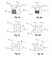
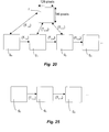
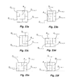
- Figures 8a to 8f depict different examples of source block selection.
- the block to be coded A n,m of the image under consideration f n has been superimposed on the source blocks D n-1,m,1 to D n-1,m4 of the source image g n-1 .
- four source blocks of the same size as the block to be coded A n,m are considered.
- the block to be coded A n,m is in a central part of the image f; the four source blocks are adjacent and the block to be coded is centred overall on the set of the four selected source blocks.
- the block to be coded A n,m is situated on an edge of the image represented by a dotted line.
- Two of the source blocks partially overlap the other two source blocks, so that the block to be coded overlaps part of each source block.
- the block to be coded A n,m is in a corner of the image, and the four source blocks partially overlap one another, so that the block to be coded overlaps part of each source block.
- the four source blocks are adjacent, and two or three of the source blocks are truncated and made up either by a uniformly grey remainder, or by a remainder determined by extension of the image for example by symmetry or by periodization of the image.
- the step E7 is followed by the step E8, at which a transformation between the source blocks and the block to be coded is calculated.
- a n,m,k is a scaling function, here a constant function, or coefficient, for a given source block D n-1,m,k and as a norm less than unity
- b n,m is a grey scale offset function, here a constant function, or coefficient, for the block to be coded A n,m .
- the function a n,m,k is applied to each pixel of the block D n-1,m,k , which here amounts to multiplying all the pixels by the coefficient a n,m,k .
- the functions, here the coefficients a n,m,k and b n,m , are determined in order to minimise a distance d(A n,m , AR n,m ) between the block to be coded A n,m and the block AR n,m reconstructed by applying the transformation T n,m to the source blocks according to the formula given above.
- the functions a n,m,k and b n,m are made discrete, and a limited number of possible values for the coefficients a n,m,k are tested.
- each coefficient a n,m,k may take two integer values, a positive value and the opposite value. All combinations of coefficients a n,m,k are tested, and, for each combination, the coefficient b n,m is chosen to minimise the envisaged distance.
- the distance is calculated between the grey levels of the block to be coded A n,m and the grey levels of the block AR n,m resulting from the application of the transformation to the source blocks D n-1,m,1 to D n-1,m,K .
- the distance may be the absolute value of the sum of the differences, or the root mean square error, or the absolute value of the greatest difference, calculated between the source block A n,m and the block AR n,m reconstructed by applying the transformation T n,m to the source blocks.
- the distance is the root mean square error calculated between the grey levels of the block to be coded A n,m and the grey levels of the block AR n,m resulting from application of the transformation to the source blocks D n-1,m,1 to D n-1,m,K .
- the combination T n,m ⁇ a n,m,k , b n,m ⁇ which minimises the distance is stored at step E9 in the memory 25 of the coding device 2 ( Figure 3) as a compressed form of the block A n,m .
- the set of transformations T n,m relating to the image f n forms a compressed image h n .
- step E10 is a test to check whether m is equal to M, that is to say whether the block which has just been coded is the last in the current image. If there remains at least one block to be coded in the image f n , the step E10 is followed by the step E11 at which the parameter m is incremented by one unit, in order to consider the next block in the image f n . The step E11 is followed by the step E7 described previously.
- step E10 is followed by step E12 which is a test for checking whether the image f n which has just been compressed is the last in the sequence. If this is not the case, step E12 is followed by step E13, which is the construction of the decompressed image g n .
- the application of each of the transformations T n,m previously determined to the source blocks reconstructs each of the blocks AR n,m , which as a whole form the decoded image g n .
- the image g n is stored in memory 25 in order to be used for the coding of the following image f n+1 (step E6).
- the step E13 is followed by the step E14 in order to increment the parameter n by one unit.
- the step E14 is followed by the step E2 described previously.
- n N, that is to say for the last image of the sequence, it is not necessary in this case to reconstruct the image g N .
- the coding method is modified as follows.
- the source blocks are no longer selected for each of the image blocks to be coded; source blocks are selected from the reference image, once and for all for the image to be coded and are thereafter used to code all the blocks of the image to be coded.
- the coding is thus faster, since selection of the source blocks is performed only once per image; the distortions introduced by the coding will however be greater than with the embodiment described previously.
- the first embodiment of a compressed digital image decoding algorithm consists of steps E20 to E30.
- the step E20 is an initialisation at which the parameter n is initialised to 1, for treating the first compressed image h 1 of the sequence.
- a supplementary image g 0 is added to the sequence as a source image for the first compressed image h 1 of the sequence.
- the supplementary image g 0 is identical to the one considered at the step E4 described previously, and is for example a uniformly grey image.
- step E22 is the initialisation of the parameter m to 1, in order to consider the first block to be reconstructed.
- the blocks are preferably processed in the same order as at compression, which avoids having to store and process an index, or coordinates, in order to identify the blocks.
- the following step E23 is division of the reference image g n-1 into blocks of adjacent pixels, which are the source blocks stored in memory 55.
- the step E23 is identical to the step E6.
- the following step E24 is the selection of source blocks D n-1,m,1 to D n-1,m,K from the reference image g n-1 , with regard to the block to be reconstructed AR n,m .
- the reference image is selected in the same way as for coding, with the same possible variants.
- the reference image g n-1 is the decoded image preceding the image h n .
- the source blocks are selected in the same way as for coding (step E6), with the same possible variants.
- the result of the step E25 is the decoded block AR n,m stored in memory 55.
- step E26 is a test to determine whether the block which has just been decompressed is the last in the image in the process of decompression. If this is not the case, the step E26 is followed by the step E27 at which the parameter m is incremented by one unit in order to consider the next block. The step E27 is followed by the step E24 described previously.
- the step E26 is followed by the step E28 at which the decompressed image g n is reconstructed and for example displayed on a screen, and/or stored.
- the step E28 is the transfer of the image g n to the user means 6.
- step E29 is a test to determine whether the image which has just been decompressed is the last image of the sequence. If there remains at least one image to be decompressed, the step E29 is followed by the step E30 at which the parameter n is incremented by one unit, in order to consider the following image in the sequence. The step E30 is followed by the step E22 described previously.
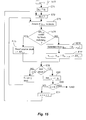
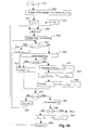
- FIG. 10 Another embodiment of the coding method according to the invention is depicted in Figures 10, 11 and 12 in the form of an algorithm having steps E31 to E41 stored in memory 23 ( Figure 3).
- the size of the blocks to be coded is determined in an adaptative fashion, according to the quantity of information present in the blocks to be coded and according to the « movement » of the blocks to be coded with respect to the reference image, that is to say the modifications between the pixels in the block to be coded and the pixels in the source blocks of the reference image.
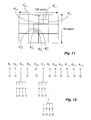
- a division tree in this case a quaternary tree, is associated with each image to be coded.
- the quaternary tree represents the particular division of each image.
- Each compressed image h n has a set of transformations ⁇ T n,m ⁇ and the associated quaternary tree.
- Step E31 is an initialisation of a parameter n à 1, to consider first of all the first image f 1 of the sequence.
- step E32 is the division of the current image f n into blocks of initial size.
- the image f n has a size of 128 x 96 pixels, and is divided into twelve blocks of size 32 x 32 pixels.
- Each block of initial size A n,1 to A n,12 is associated with a root of the quaternary tree depicted in Figure 12, that is to say with a node of the tree which has no associated data and which has not yet been sub-divided.
- a marker is initialised to the value zero for each root.
- step E33 is the seeking of a transformation between a block A n,m of the image to be coded f n and source blocks. Step E33 is similar to steps E3 to E8 previously detailed with reference to Figure 5.
- step E33 is a transformation T n,m determined for the block to be coded A n,m .
- the different variants possible for selecting the reference images and source blocks, for the choice of the transformation and the distance, previously disclosed, are here applicable in the same way as for the first embodiment.
- step E34 is a test for determining whether the distance d(A n,m , AR n,m ) calculated at the previous step is below a predetermined threshold S.
- step E34 is followed by step E35 at which the transformation T n,m is stored as a data block D associated with the node of the block A n,m , in the quaternary tree of the image f n .
- the marker remains at the value zero.
- the reconstructed block AR n,m is calculated and stored to memory in order to construct the image g n .
- Step E35 is followed by step E36, at which a test is carried out to determine whether the block which has just been processed is the last in the image in the course of coding. If this is not the case, step E36 is followed by step E37 in order to consider another block of the image f n . Step E37 is followed by the previously described E33.
- step E36 is followed by step E38 at which a test is carried out to determine whether all the images in the sequence have been processed. If there remains at least one image to be coded, step E38 is followed by step E39 in order to consider another image in the sequence. Step E39 is followed by step E32.
- step E34 If, at step E34, the distance d(A n,m AR n,m ) calculated at the previous step E33 is greater than the threshold S, step E33 is followed by step E40 at which a test is carried out to determine whether the size of the current block to be coded A n,m has attained a predetermined minimal value. If the response is positive, step E40 is followed by step E35, that is to say the determined transformation is stored to memory, even if it does not satisfy the criterion of step E34, in cases where the size of the current block to be coded A n,m has attained the minimum value.
- step E41 at which the current block to be coded at A n,m is divided into a predetermined number M1 of sub blocks A 1 n,m to A M1 n,m .
- the division is for example effected in four sub-blocks.
- the marker of the node associated with the divided block A n,m is set to the value 1, in order to indicate that the corresponding block has been divided.
- the division of the block results in four sub-blocks, whose nodes in the quaternary tree have markers initialised to zero.
- the order of the sub-blocks in the quaternary tree corresponds to their position in the divided block, and this order is the same for all the divided blocks: for example, bottom right sub-block, bottom left sub-block, top right sub-block, top left sub-block.
- the position information of the sub-blocks is used on decoding.
- Step E41 is followed by the step E33 of calculating a transformation, for each of the sub-blocks determined at step E41.
- Each of these sub-blocks is coded in the same way as a block A n,m .
- the following steps are run through successively for each sub-block A 1 n,m to A M1 nm , which leads notably to the determination of a transformation for the current sub-block, and to its storage in memory if the criterion of step E34 is satisfied, or if the minimum sub-block size is attained (step E40).
- step E34 For each sub-block, if the criterion of step E34 is not satisfied, and if the minimum sub-block size has not been attained (step E40), the sub-block under consideration is itself divided at step E41 into sub-blocks of a smaller size.
- the image f n is divided into twelve blocks A n,1 to A n,12 , the blocks A n,3 and A n,6 are divided into four sub-blocks, and one of these sub-blocks A 4 n,6 is divided into four sub-blocks A 4,1 n,6 , A 4,2 n,6 , A 4,3 n,6 and A 4,4 n,6 .
- the coding of an image f n of the sequence results in a compressed image h n having a set of transformations ⁇ T n,m ⁇ associated with a quaternary tree.
- the decoding algorithm corresponding to this embodiment is depicted in Figure 13 and includes steps E200 to E300 respectively analagous to steps E20 to E30 of the algorithm described with reference to Figure 9 with the following modifications :
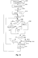
- FIG. 14 Another embodiment of the coding method according to the invention is depicted in Figure 14 , and includes steps E51 to E67 stored in memory 23 ( Figure 3).
- this embodiment consists of first of all seeking, for each block to be coded, whether it can be coded by matching with a block of the reference image. If this coding is possible, the block is coded by block matching; otherwise the block is coded by means of a transformation determined as in the first embodiment.
- Steps E51 to E56 are identical to steps E1 to E6 previously described with reference to the first embodiment (figure 5).
- Step E56 is followed by step E57 at which the current block to be coded A n,m is coded by block matching: in the reference image g n-1 , a matching block D n-1,m,j is sought which is as similar as possible to the block to be coded, according to a predetermined criterion, for example a measurement of distance d(A n,m , D n-1,m,j ) between the block to be coded and the matching block. As disclosed above, different types of distance can be used. The matching block for which the criterion is minimised is selected.
- step E58 is a test for checking whether the criterion is below a predetermined threshold. If the response is positive, the relative postion of the matching block D n-1,m,j , in the reference image g n-1 , with respect to the position of the block to be coded A n,m , in the image in the course of coding f n , that is to say the movement vector V n,m,j , is stored in memory 25, at step E59.
- An indicator I n,m is also stored to memory, in order to indicate that the block under consideration is coded by block matching. This indicator is for example an additional bit set to the value one.
- the movement vector V n,m,j and the indicator I n,m represent the coding information of the block A n,m .
- Step E59 is followed by steps E63 to E67, respectively identical to the previously described steps E10 to E14.
- step E58 is followed by steps E60 to E67, respectively analogous to the previously described steps E7 to E14.
- Step E61 results in a transformation T n,m .
- the indicator I n,m for example the additional bit set to the value zero, is associated with each transformation T n,m .
- the two previous embodiments are combined: it is sought first of all to code the blocks by block matching and then, if this first coding is not possible, by means of a transformation; the steps of coding by determination of a transformation include then the variation of the size of the block to be coded as a function of a criterion.
- the coding method corresponding to the coding of Figure 14 is depicted in Figure 15 and includes steps E70 to E91 stored in memory 53 of the device 5 ( Figure 4).
- Steps E70 to E73 are respectively identical to the steps E20 to E23 described with reference to Figure 9.
- step E74 is a test for determining whether the block in the course of construction AR n,m has been coded by block matching.
- the test consists of analysing the value of the indicator I n,m and seeking whether the indicator I n,m is at the value one.
- step E75 consists of reading in the reference image g n-1 the matching block D n-1,m,j which is determined by the movement vector forming the compressed form V n,m,j and copying this block as a decoded block AR n,m .
- Step E75 is followed by steps E78 to E91, which are respectively identical to the previously described steps E25 to E30 ( Figure 9).
- step E74 is followed by steps E76 to E91, which are respectively identical to the previously described steps E24 to E30 ( Figure 9).
- FIG. 16 Another embodiment of the coding method according to the invention is depicted in Figure 16 and includes steps E401 to E414 stored in memory 23 ( Figure 3).
- this embodiment consists of dividing each image to be coded into zones, analysing the zones in order to determine whether they are fixed or movable, then coding the fixed zones according to a fixed image coding method, and the movable zones as in the first embodiment.
- Step E401 is the division of each of the images into predetermined zones Z n,1 to Z n,E , where E is an integer equal to five for example.
- Figure 17 depicts the image f n divided into five zones Z n,1 to Z n,E which are bands of the same size.
- the following step E402 is an analysis of the zones in order to determine whether each of the zones Z n,e is « fixed » or « movable NOTE
- Fixed zone means a zone which is identical to (or very little different from,) the zone having the same position in the previous image in the sequence. Conversely, the zone is said to be movable if it is sufficiently different from the zone which had the same position in the previous image in the sequence.
- the difference between the zone in the course of processing and the zone having the same location in the previous image is assessed by measuring the distance between the two zones and comparing the distance with a threshold.
- a zone indicator IN n,e is associated with each of the zones in order to indicate whether the zone in question is fixed or movable.
- the zone indicator IN n,e includes for example a bit set to one or to zero in order to signify fixed zone or movable zone.
- Step E402 is followed by step E403, which is an initialisation at which the parameter n is initialised to one, in order to consider first of all the first image f 1 in the sequence.
- Step E403 is followed by step E404 at which the first image f 1 of the sequence is coded according to a fixed image coding method.
- This method is for example a method of the JPEG (Joint Picture Expert Group) type, or the coding method described hereinafter.
- the coding type in this case fixed image coding, is stored by an indicator. This indicator is stored only during coding and is not associated with the coded form of the zones of the image f 1 .
- the parameter n is incremented by one in order next to consider the folowing image f 2 .
- step E405 is an initialisation of a parameter e to 1, in order to consider the first zone Z n,1 in the current image f n .
- step E406 is a test for determining whether the current zone Z n,e is fixed or movable.
- the test consists of reading and analysing the value of the zone indicator IN n,e .
- step E406 is followed by step E407, at which the zone Z n,e is divided into blocks, each block is then coded by a transformation T n,m between the block and the source blocks taken from the reference image.
- Step E407 is equivalent to the previously described steps E2 and E5 to E11 ( Figure 5).
- step E406 is followed by step E408, which is a test for determining whether the zone has already been coded during the coding of a previous image. This test consists of reading the coding type indicator of the relevant zone of the previous image.
- step E409 at which the zone Z n,e is coded according to the fixed image coding method, for example the method of the JPEG (Joint Picture Expert Group) type, or the coding method method described hereinafter.
- the coding type indicator indicates that the zone under consideration is coded according to a fixed image coding.
- the zone under consideration is not coded.
- a fixed zone in several successive images is coded only once for the first of these images, and is then not coded for the following images. Consequently coding is fast and requires few bits.
- step E410 is a test for checking whether e is equal to E, that is to say whether the zone which has just been coded is the last zone to be coded in the current image f n . If there remains at least one zone to be coded in the image f n , step E410 is followed by step E411, at which the parameter e is incremented by one unit, in order to consider the following zone in the image f n . Step E411 is followed by the previously described step E406.
- step E410 is followed by step E412, which is a test for checking whether the image f n which has just been compressed is the last in the sequence. If this is not the case, step E412 is followed by step E413, which is the construction of the movable zones of the decompressed image g n .
- a movable zone is reconstructed by appylying each of the previously determined transformations T n,m to the source blocks in order to form blocks AR nm .
- the movable zones of the image g n are stored in memory 25 in order to be used for coding the movable zones of the following image f n+1 .
- Step E413 is followed by step E414 for incrementing the parameter n by one unit.
- the zones are analysed along with the coding of the images.
- the decoding method corresponding to the coding of Figure 16 is depicted in Figure 18 and includes steps E520 to E530 stored in memory 53 of the device 5 ( Figure 4).
- Step E520 is an initialisation at which the parameter n is initialised to 1, in order to process the first compressed image h 1 in the sequence.
- the first compressed image h 1 of the sequence is decoded according to a method which depends on the coding method of the previously described step E409.
- the parameter n is incremented by one in order to pass to the following image h 2 .
- step E522 is the initialisation of the parameter e to 1, in order to consider the first zone to be reconstructed.
- the zones are preferably processed in the same order as on compression, which avoids having to store and process an index, or coordinates, in order to mark the zones.
- step E523 is a test for determining whether the current zone has been coded as a fixed zone or as a movable zone.
- the test consists of reading the value of the zone indicator IN n,e .
- step E523 is followed by step E524, at which a test is carried out to determine whether the zone which had the same location in the previous image was decoded when step E526 was previously effected.
- Step E524 is followed by step E525 at which this previously decoded zone is copied as a decoded zone for the current zone of the current image. If the zone having the same location in the previous image has not been decoded, step E524 is followed by step E526 at which the current zone is decoded according to a method whch depends on the coding method.
- a decoded zone indicator is stored to memory in order to be tested when step E524 is subsequently performed. Thus a zone which is fixed in several successive images is decoded for the first of these images and is then copied for the following images.
- step E523 is followed by step E527, at which the movable zone is decoded.
- Source blocks D n-1,m,1 to D n-1,m,K are selected from the reference image g n-1 , relative to each block to be reconstructed AR n,m in the current zone.
- Step E527 results in the decoded blocks AR n,m of the current zone, which are stored in memory 55.
- step E528 is a test for determining whether the zone which has just been decompressed is the last in the image in the course of decompression. If this is not the case, step E528 is followed by step E529 at which the parameter e is incremented by one unit in order to consider the following zone. Step E529 is followed by the previously described step E523.
- step E528 is followed by step E530, at which the decompressed image g n is reconstructed and for example displayed on a screen, and/or stored to memory.
- step E530 is the transfer of the image g n to user means 6.
- step E531 is a test for determining whether the image which has just been decompressed is the last image in the sequence. If there remains at least one image to be decompressed, step E531 is followed by step E532, at which the parameter n is incremented by one unit, in order to consider the following image in the sequence. Step E532 is followed by the previously described step E522.
- Figures 19 to 35 more particularly relate to still, or fixed, images.
- Such an image is coded progressively, according to a number of coding iterations.
- the result of an iteration is equivalent to an image of a sequence.
- the series of images obtained at the consecutive iterations is equivalent to an image sequence, and the processing which will be now detailed is analogous to the previous one.
- the invention applies to the coding of a set of data representing physical quantities which is a digital image f, here a grey scale image, having by way of example 128 x 96 pixels with 256 levels.
- the algorithm depicted in Figure 19 has steps S1 to S15 which carry out the coding of the digital image.
- the image is coded progressively, according to a number of coding iterations.
- the result of coding of each iteration may be transmitted, so that the coded image is transmitted progressively, with a limited transmission speed.
- the step S1 is an initialisation at which the source 1 provides an image to be coded f to the coding device 2.
- the number M of blocks is determined according to the size of the image.
- a number of coding iterations IT is also determined.
- the number of coding iterations IT is analogous to the number N previously described, and the series of images resulting of the coding iterations is analogous to a images sequence.
- the parameters M and IT may be predetermined or set by a user.
- step S2 is a division of the image under consideration f into the number M of blocks A 1 to A M of adjacent pixels.
- the blocks A 1 to A M are adjacent, without overlapping.
- the blocks may overlap one another, in order to limit block effects at decoding, to the detriment of the compression ratio.
- the blocks all have the same predetermined size, and are for example square blocks A 1 to A 12 of 32 x 32 pixels in the case of the 128 x 96 pixel image. Division of the image f is uniform within the whole image.
- the size of the blocks whilst being predetermined, depends on the location of the blocks in the image: in a predetermined area of the image f, for example a central area liable to contain more detail, the blocks are smaller than on the edges of the image. This specific area will then be coded more finely than the rest of the image.
- the result of division of the image is a set of M blocks A 1 to A M , stored in memory 25.
- the blocks A 1 to A M will be compressed, or coded, one after another, in any order.
- This order is preferably predetermined and is then the order in which the blocks will next be decompressed, or decoded, which makes it unnecessary to identify the blocks by means of an index or coordinates.
- the step S2 is followed by the step S3, which is initialisation of a parameter i to 1, in order to start the first coding iteration.
- the step S3 is followed by the step S4 at which a supplementary image g 0 is considered as a reference image for the first coding iteration.
- the supplementary image g 0 is any image, for example a uniformly grey image.
- the step S4 is followed by the step S5, which is initialisation of a parameter m to 1, in order to consider the first block A 1 in the image f.
- the following step S6 is the division of a reference image into blocks of adjacent pixels, stored in memory 25.
- the size of the blocks depends on the size of the blocks to be coded A m .
- the reference image blocks are F 2 times larger than the blocks to be coded, where F is an integer for example equal to two, which makes it possible to use a lot of detail in the reference image.
- the reference image blocks are next sub-sampled by the factor F, in order to work on blocks having the same number of pixels as the blocks to be coded. According to a variant which is simpler to implement, the reference image blocks have the same size as the blocks to be coded.
- the reference image g i-1 is the image coded and then decoded according to the invention during the iteration preceding the coding iteration in progress, except for the first iteration, for which the reference image g 0 is predetermined.
- step S6 is followed by the step S7, which is the selection of source blocks D i-1,m,1 to D i-1,m,K from the reference image with regard to the block to be coded A m of the image f.
- the number K of source blocks is predetermined, and is equal for example to 4.
- the number K is a set-up parameter of the algorithm.
- the source blocks are selected by their location in the reference image g i-1 according to the location of the block to be coded A m in the image f.
- the source blocks are selected from a region of the reference image which depends on the region of the block to be coded in the image under consideration.
- the two regions are similar, that is to say the superimposition of the image under consideration and the reference image leads to partial overlapping of the block to be coded and the source blocks.
- Figures 23a to 23f depict different examples of source block selection.
- the block to be coded A m of the image under consideration f has been superimposed on the source blocks D i-1,m,1 to D i-1,m,4 of the source image g i-1 .
- four source blocks of the same size as the block to be coded A m are considered.
- the block to be coded A m is in a central part of the image f; the four source blocks are adjacent and the block to be coded is centred overall on the set of the four selected source blocks.
- the block to be coded A m is situated on an edge of the image represented by a dotted line. Two of the source blocks partially overlap the other two source blocks, so that the block to be coded overlaps part of each source block.
- the block to be coded A m is in a corner of the image, and the four source blocks partially overlap one another, so that the block to be coded overlaps part of each source block.
- the four source blocks are adjacent, and two or three of the source blocks are truncated and made up either by a uniformly grey remainder, or by a remainder determined by extension of the image for example by symmetry or by periodization of the image.
- the step S7 is followed by the step S8, at which a transformation between the source blocks and the block to be coded is calculated.
- a i,m,k is a scaling function, here a constant function, or coefficient, for a given source block D i-1,m,k and as a norm less than unity
- b i,m is a grey scale offset function, here a constant function, or coefficient, for the block to be coded A m at the iteration n.
- the function a i,m,k is applied to each pixel of the block D i-1,m,k , which here amounts to multiplying all the pixels by the coefficient a i,m,k .
- the functions, here the coefficients a i,m,k and b i,m , are determined in order to minimise a distance d(A m , AR i,m ) between the block to be coded A m and the block AR i,m reconstructed at the iteration i by applying the transformation T i,m to the source blocks according to the formula given above.
- the functions a i,m,k and b i,m are made discrete, and a limited number of possible values for the coefficients a i,m,k are tested.
- each coefficient a i,m,k may take two integer values, a positive value and the opposite value. All combinations of coefficients a i,m,k are tested, and, for each combination, the coefficient b i,m is chosen to minimise the envisaged distance.
- the distance is calculated between the grey levels of the block to be coded A m and the grey levels of the block AR i,m resulting from application of the approximation to the source blocks D i-1,m,1 to D i-1,m,K .
- the distance may be the absolute value of the sum of the differences, or the root mean square error, or the absolute value of the greatest difference, calculated between the source block A m and the block reconstructed by applying the transformation T i,m to the source blocks.
- the distance is the root mean square error calculated between the grey levels of the block to be coded A m and the grey levels of the block AR i,m resulting from application of the transformation to the source blocks D i-1,m,1 to D i-1,m,K .
- step S10 is a test to check whether m is equal to M, that is to say whether the block which has just been coded is the last in the image f. If there remains at least one block to be coded in the image f, the step S10 is followed by the step S11 at which the parameter m is incremented by one unit, in order to consider the next block in the image f. The step S11 is followed by the step S7 described previously.
- step S10 is followed by the step S12, which is the transmission of the compressed image h i .
- This transmission is one step of the progressive transmission of the coded image and will enable the decoding device to decode an approximation of the image, as described subsequently.
- step S13 is a test to check whether all the iterations for coding the image f have been performed. If this is not the case, the step S13 is followed by the step S14 which is the construction of the decompressed image g i .
- Application of each of the previously determined transformations T i,m to the source blocks reconstructs each of the blocks AR i,m , which as a whole form the decoded image g i .
- the image g i is stored in memory 25 in order to be used as a reference image at the following iteration i+1.
- the step S14 is followed by the step S15 in order to increment the parameter i by one unit.
- the step S15 is followed by the step S5 described previously.
- i IT, that is to say for the last iteration for coding the image f, it is not necessary in this case to reconstruct the image g IT .
- the coding method is modified as follows.
- a reference image chosen as described above, is considered at each iteration.
- the source blocks are no longer selected for each of the image blocks to be coded; source blocks are selected from the reference image, once and for all for each iteration, and are then used to code all the image blocks to be coded.
- the coding is thus faster, since selection of the source blocks is performed only once per iteration; the distortions introduced by the coding will however be greater than with the embodiment described previously.
- an embodiment of a progressive compressed digital image decoding algorithm consists of steps S20 to S30.
- the step S20 is an initialisation at which the parameter i is initialised to 1, for the first decoding iteration.
- a supplementary image g 0 is considered as a source image for the first decoding iteration.
- the supplementary image g 0 is identical to the one considered at the step S4 described previously, and is for example a uniformly grey image.
- the compressed form h i of the image is considered.
- the step S22 is the reading of the compressed form h i , and initialisation of the parameter m to 1, in order to consider the first block to be reconstructed.
- the blocks are preferably processed in the same order as at compression, which avoids having to store and process an index, or coordinates, in order to identify the blocks.
- the following step S23 is division of the reference image g i-1 into blocks of adjacent pixels, which are the source blocks stored in memory 55.
- the step S23 is identical to the step S6.
- the following step S24 is the selection of source blocks D i-1,m,1 to D i-1,m,K from the reference image g i-1 , with regard to the block to be reconstructed AR i,m of the image to be decompressed h i .
- the reference image is selected in the same way as for coding.
- the reference image g i-1 is the decoded image preceding the image h i .
- the source blocks are selected in the same way as for coding, with the same possible variants.
- the result of the step S25 is the decompressed block AR i,m stored in memory 55.
- step S26 is a test to determine whether the block which has just been decompressed is the last in the image in the process of decompression. If this is not the case, the step S26 is followed by the step S27 at which the parameter m is incremented by one unit in order to consider the next block. The step S27 is followed by the step S24 described previously.
- the step S26 is followed by the step S28 at which the decompressed image g i is reconstructed and for example displayed on a screen, and/or stored.
- the step S28 is the transfer of the image g i to the user means 6.
- step S29 is a test to determine whether all the iterations have been performed. If there remains at least one iteration to be performed, the step S29 is followed by the step S30 at which the parameter i is incremented by one unit, in order to move to the next iteration. The step S30 is followed by the step S22 described previously.
- the image g 1 is reconstructed first of all, then the image g 2 , and so on, as depicted in Figure 11, which enables a progressive construction of the decoded image, each iteration making it possible to obtain an image having more detail than at the preceding iteration.
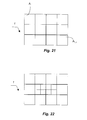
- FIG. 26 and 27 Another embodiment of the coding method according to the invention is depicted in Figures 26 and 27 in the form of an algorithm having steps S31 to S45 stored in memory 23 ( Figure 3).
- the size of the blocks to be coded decreases, and the number of blocks to be coded increases correlatively, at each coding iteration, so as to code finer and finer details.
- the aim of the first coding iteration is to calculate a first set of transformations ⁇ T 1,m ⁇ , each of these transformations corresponding to the coding of a block of the image f from source blocks of the image g 0 .
- the transformations are applied to the source blocks of the image g 0 in order to determine the image g 1 .
- the aim of the second coding iteration is to calculate a second set of transformations ⁇ T 2,m ⁇ , each of these transformations corresponding to the coding of a block of the image f from source blocks of the image g 1 .
- the blocks of the image f have, for this iteration, a size smaller than that of the blocks considered at the preceding iteration.
- the source blocks also have a size smaller than those of the preceding iteration.
- the transformations are applied to the source blocks of the image g 1 in order to determine the image g 2 .
- the third iteration uses the image g 2 as a reference image, and a set of transformations ⁇ T 3m ⁇ is determined between blocks of the image f and source blocks of the image g 2 , the size of the blocks to be coded and the reference blocks being reduced compared with the preceding iteration. This iteration makes it possible to calculate the image g 3 .
- the decoding algorithm corresponding to this embodiment is identical to that depicted in Figure 24.
- Figure 28 depicts the successive decoding iterations.
- the first set of transformations ⁇ T 1,m ⁇ is applied to the respective blocks, having the first predetermined size t 1 , of the image g 0 .
- the image g 1 is thus reconstructed.
- the image g 1 is divided into blocks having the second predetermined size t 2 , then the second set of transformations is applied to the blocks of the image g 1 , in order to form the image g 2 , and so on.
- the images reconstructed as the iterations are performed contain finer and finer details.
- FIG. 29 Another embodiment of the coding method according to the invention is depicted in Figure 29, and consists of steps S51 to S691 stored in memory 23 ( Figure 3).
- This embodiment includes first of all a test, for each block to be coded, as to whether it can be coded by matching with the reference image block which has the same size and occupies the same position in the image. If this coding is possible, the block is coded by block matching; otherwise, the block is coded by means of a transformation determined as in the first embodiment.
- the steps S51 to S56 are identical to the steps S1 to S6 described previously with reference to Figure 19.
- the step S56 is followed by the step S57 which is a test to determine whether the current block to be coded A m was coded by block matching at the preceding iteration. This test is carried out on a flag I i-1,m , for example a bit set to the value 1 if the block A m is coded by block matching at the iteration i-1.
- step S58 is followed by the step S59, at which a flag I i,m is stored at the step S59, to indicate that the block under consideration is coded by block matching.
- This flag is for example a bit set to the value 1.
- the flag I i,m represents the coding information, at the iteration i, of the block A m .
- step S58 If the reply is negative at the step S58, the latter is followed by the step S60 at which the current block to be coded A m is coded by block matching: the block AR i-1,m of the same size and having the same position in the image is looked for in the reference image g i-1 .
- the following step S61 is a test to check whether a criterion is met.
- This criterion here consists of checking whether a distance calculated between the block to be coded A m and the matching block AR i-1,m is less than a predetermined threshold. If the reply is positive, a flag I i,m is stored at the step S59, to indicate that the block under consideration is coded by block matching. This flag is for example a bit set to the value 1.
- the flag I i,m represents the coding information, at the iteration i, of the block A m .
- the step S59 is followed by the steps S65 to S691, respectively identical to the steps S10 to S15 described previously.
- step S61 is followed by the steps S62 to S691, respectively identical to the steps S7 to S15 described previously.
- the result of the step S63 is a transformation T i,m .
- the flag I i,m is set to the value zero and is associated with each transformation T i,m .
- the two preceding embodiments are combined: an attempt is made first of all to code the blocks by block matching, and next, if this first coding is not possible, by means of a transformation; the steps of coding by determining a transformation then include varying the size of the block to be coded as the iterations are performed. In this case, the steps S57 and S58 are unnecessary, since the size of the blocks varies from one iteration to the next.
- the step S56 is then followed directly by the block matching step S60.
- the decoding method corresponding to the coding of Figure 29 is depicted in Figure 30 and consists of steps S70 to S91 stored in memory 53 of the device 5 ( Figure 4).
- the steps S70 to S73 are respectively identical to the steps S20 to S23 described with reference to Figure 24.
- step S74 is a test to determine whether the block in the process of reconstruction AR i,m was coded by block matching.
- the test consists of analysing the value of the flag I i,m and of testing as to whether the flag I i,m is at the value 1.
- step S75 consists of reading, from the reference image g i-1 , the matching block AR i-1,m and of copying this block as the decoded block AR i,m . Reconstruction of the block AR i,m is therefore very quick, since one block copy is involved.
- the step S75 is followed by the steps S78 to S91, which are respectively identical to the steps S25 to S30 described previously ( Figure 24).
- step S74 is followed by the steps S76 to S91, which are respectively identical to the steps S24 to S30 described previously ( Figure 24).
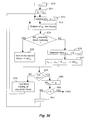
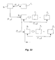
- FIG. 31 to 33 Another embodiment of the coding method according to the invention is depicted in Figures 31 to 33 , and consists of steps S101 to S115 stored in memory 23 ( Figure 3).
- This embodiment includes working at each iteration on image differences and coding only the details which are additional compared with the preceding iteration.
- the steps S101 and S102 are identical to the steps S1 and S2 described previously ( Figure 19).
- the following step S103 is the calculation of the mean value M 1 to M M of each of the blocks A 1 to A M of the image f, and the subtraction, pixel by pixel, of this mean value M m from each of the blocks A m .
- the result of the step S103 is an image f' 1 , as depicted in Figure 32 .
- the image z 0 of the mean values has a compressed form h 0 having the mean value M 1 to M M of each of the blocks A m .
- the compressed form h 0 is stored and/or transmitted in order to be used at the time of decoding.
- the step S103 is followed by the step S104, which is the division into blocks A 1,1 to A 1,M of the image f' 1 .
- the steps S103 and S104 are removed, and the image f is worked on directly, as in the preceding embodiments.
- step S105 is initialisation of a parameter i to 1, in order to start the first coding iteration.
- a supplementary image g 0 is considered as a reference image for the first coding iteration.
- the supplementary image g 0 is any image, for example a uniformly black image where image differences are being worked on.
- An image f' i is equal to the image f' 1 .
- the step S105 is followed by the step S106, which is initialisation of a parameter m to 1, in order to consider the first block A i,1 in the image to be coded at the iteration i, that is the image f' i .
- step S107 is division of the reference image g i-1 into blocks of adjacent pixels, stored in memory 25.
- step S107 is followed by the step S108, which is the selection of source blocks D i-1,m,1 to D i-1,m,K from the reference image with regard to the block to be coded A i,m of the image to be coded f' i .
- the step S108 is followed by the step S109, at which a transformation T i,m between the selected source blocks and the block to be coded is calculated.
- the transformation T i,m which minimises the distance d(A i,m , AR i,m ) is stored in the memory 25 of the coding device 2 ( Figure 3) as a compressed form of the block A i,m .
- the set of compressed blocks ⁇ T i,m ⁇ determined at the iteration n forms a compressed image h i .
- step S110 is a test to check whether m is equal to M, that is to say whether the block which has just been coded is the last in the current image f' i . If there remains at least one block to be coded in the image f' i , the step S110 is followed by the step S111 at which the parameter m is incremented by one unit, in order to consider the next block in the image f' i . The step S111 is followed by the step S107 described previously.
- step S110 is followed by the step S112, which is the transmission of the compressed image h i .
- This transmission is one step of the progressive transmission of the coded image and will enable the decoding device to decode an approximation of the image, as described subsequently.
- step S113 is a test to check whether all the iterations for coding the image f have been performed. If this is not the case, the step S113 is followed by the step S114, which is the construction of the decompressed image g i .
- Application of each of the previously determined transformations T i,m to the source blocks reconstructs each of the blocks AR i,m , which as a whole form the decoded image g i .
- the image g i is stored in memory 25 in order to be used as a reference image at the next iteration i+1.
- the image f' i+1 to be coded at the next iteration i+1 is determined by subtracting the image f' i from the image g i .
- the step S114 is followed by the step S115 in order to divide the image f' i+1 into blocks to be coded A i+1,1 to A i+1,M . These blocks will be coded at the following iteration.
- step S116 increments the parameter i by one unit in order to move to the next iteration.
- step S116 is followed by the step S106 described previously.
- i IT, that is to say for the last iteration for coding the image f, it is not necessary in this case to reconstruct the image g IT .
- the decoding method corresponding to the coding of Figure 31 is depicted in Figures 34 and 35 and consists of steps S201 to S211 stored in memory 53 of the device 5 ( Figure 4).
- the step S201 is an initialisation at which the parameter i is initialised to 1, for the first decoding iteration.
- a supplementary image g 0 is considered as a source image for the first decoding iteration.
- the supplementary image g 0 is identical to the one considered at the step S105 described previously, and is for example a uniformly black image.
- the compressed mean image h 0 is considered.
- step S203 is the reading of the compressed file h i , and initialisation of the parameter m to 1, in order to consider the first block to be reconstructed.
- the blocks are preferably processed in the same order as at compression, which avoids having to store and process an index, or coordinates, in order to identify the blocks.
- the following step S204 is division of the reference image g i-1 into blocks of adjacent pixels, which are the source blocks stored in memory 55.
- the step S204 is identical to the step S107.
- the following step S205 is the selection of source blocks D i-1,m,1 to D i-1,m,K from the reference image g i-1 , with regard to the block to be reconstructed AR i,m of the image to be decompressed g i .
- the reference image is determined in the same way as for coding.
- the source blocks are selected in the same way as for coding, with the same possible variants.
- the result of the step S206 is the decompressed block AR i,m stored in memory 55.
- step S207 is a test to determine whether the block which has just been decompressed is the last in the image in the process of decompression. If this is not the case, the step S207 is followed by the step S208 at which the parameter m is incremented by one unit in order to consider the next block. The step S208 is followed by the step S205 described previously.
- the step S207 is followed by the step S209 at which the decompressed image g i is reconstructed from the blocks AR i,m .
- the approximation z i of the image at the iteration i is determined by adding the image g i to the approximation z i-1 determined at the preceding iteration.
- the approximation z i is for example displayed on a screen, and/or stored.
- the step S209 is the transfer of the image z i to the user means 6.
- step S210 is a test to determine whether all the iterations have been performed. If there remains at least one iteration to be performed, the step S210 is followed by the step S211 at which the parameter i is incremented by one unit, in order to move to the next iteration. The step S211 is followed by the step S203 described previously.
- the image z 1 is reconstructed first of all, then the image z 2 , and so on, as depicted in Figure 35, which enables a progressive construction of the decoded image, each iteration making it possible to obtain an image having more detail than at the preceding iteration.
- the invention has been described for grey-level images, that is to say images with a single component; it applies also to colour images having conventionally three components.
- These components are conventionally the red, green and blue components, or luminance and chrominance components. Each of these components is processed as exposed for an image with a single component.
Landscapes
- Engineering & Computer Science (AREA)
- Multimedia (AREA)
- Signal Processing (AREA)
- Compression, Expansion, Code Conversion, And Decoders (AREA)
- Compression Or Coding Systems Of Tv Signals (AREA)
- Compression Of Band Width Or Redundancy In Fax (AREA)
Abstract
A method of coding a set of data representing physical quantities,
the said set being composed of sub-sets (fn), is characterised in that it includes,
for each of the sub-sets, the steps of dividing (E2) the sub-set into blocks of
data to be coded (An,m), and dividing (E6) at least one reference sub-set (gn-1)
into source blocks, and then, for each of the blocks of data to be coded, the
steps of selecting (E7) a predetermined number of source blocks (Dn-1m,1 , Dn-
1,m,K), from the said at least one reference sub-set, and determining (E8) a
transformation (Tn,m) between the source blocks selected and the block to be
coded. The invention applies to the coding of image sequences.
Description
The present invention concerns, in general terms, a method and
device for coding data, and a method and device for decoding data. Data
coding and decoding relates in particular to compressing and decompressing
sets of data.
A set of compressed data can be stored to memory occupying
memory space which is small compared with the initial uncompressed set, or
can be transmitted more rapidly, or with a lower transmission speed, than the
uncompressed initial set.
These data are in principle any data and represent physical
quantities. In preferred applications, sets of data are considered which are
sequences or series of images, sound or other mono or multidimensional
signals. Hereinafter, coding and decoding of digital images and sequences of
digital images will be considered in particular, since images are known on the
one hand to occupy a large amount of memory space and on the other hand to
require a high transmission speed, or a large amount of transmission time,
when it is desired to transmit them.
As far as image sequences are concerned, many methods of coding
image sequences exist at the present time. A first type of method is the so-called
MPEG (Motion Picture Expert Group) coding which consists overall of
coding images with respect to one or more other images selected from the
sequence, referred to as reference images, and periodically an image with
respect to itself.
An image coded with respect to itself, referred to as an « intra »
image, is divided into blocks, which are coded by discreet cosine transformation
(DCT). These images are necessary for refreshing and allow random access in
the sequence; however, the degree of compression of these images is low.
An image coded with respect to one or more other images is also
divided into blocks. Each block is coded by means of an estimation and
movement compensation mechanism with respect to a block which needs to be
sought in the reference images, and then the error is coded by discreet cosine
transformation. The « best » block for coding the current block is generally
sought in a window of the reference image, in order to reduce the search time
which, otherwise, could be too long. However, this type of coding remains fairly
slow.
In addition, this type of coding is not suitable for low transmission
speeds, of around few tens of kilobits, but is limited to speeds generally greater
than 1.5 Megabits per second.
A second type of image sequence coding consists of coding a
current image in the sequence with respect to the previous image. The current
image is divided into blocks. For each block to be coded, a single block in a
dictionary consisting of the blocks of the previous image is sought, having
undergone transformation such as rotation, or symmetry. A linear
transformation is then calculated between the current block and the reference
block.
These two types of coding method have, as a common point,
seeking, for each block to be coded, a reference block in a set of blocks, which
takes a relatively long time.
In addition, the second type of coding entails decoding by iteration of
each coded block, which there again requires a relatively long time.
As far as still, or fixed, images are concerned, many image coding
methods exist at present. Among these, progressive coding methods code the
data progressively, for example by successive iterations, and the coding
accuracy increases with the coding iterations.
Progressive coding of the data enables progressive transmission of
the coded data. In the case of an image, it is possible to construct, in the
process of transmission of the image, an approximate version of the transmitted
image. The approximate version is constructed from the data already received
without waiting until all the data relating to the image have been transmitted.
The received image is gradually improved as the data are transmitted.
Progressive transmission enables a user to quickly display the
approximate version of the image. The user can interrupt the transmission in
progress if the approximate version of the image is sufficient or on the contrary
if the image is not the one desired.
For example, JPEG (Joint Picture Expert Group) coding is a method
of block coding based on discrete cosine transformations, followed by
compression by quantification and variable length coding. JPEG coding can be
progressive according to a specific so-called HJPEG (Hierarchic Joint Picture
Expert Group) mode.
HJPEG coding is relatively long and complex to implement, since it is
based on transformation calculations, in this case discrete cosine
transformation. Likewise, the decoding requires calculations of the same
complexity and length.
The present invention aims to remedy the drawbacks of the prior art
by providing a method and device for coding data, and the corresponding
decoding method and device, having a high degree of data compression, whilst
being fast in coding and decoding.
The invention is situated in the field of coding and decoding with
losses of digital image and digital image sequences by blocks.
As far as images sequences are concerned, the invention is based
on the principal of coding each image in sequence as a function of at least one
reference image.
The invention proposes a method of coding a set of data
representing physical quantities, the said set being composed of sub-sets,
characterised in that it includes, for each of the sub-sets, the steps of:
characterised in that it includes, for each of the sub-sets, the steps of:
- dividing the sub-set into blocks of data to be coded,
- dividing at least one reference sub-set into source blocks,
then, for each of the blocks of data to be coded, the steps of:- selecting a predetermined number of source blocks in the said at least one reference sub-set,
- determining a transformation between the source blocks selected and the block to be coded.
Correlatively, the invention proposes a device for coding a set of
data representing physical quantities, the said set being composed of sub-sets,
characterised in that it has:
characterised in that it has:
- means of dividing the sub-sets into blocks of data to be coded,
- means of dividing at least one reference sub-set into source blocks, for each of the sub-sets,
- means of selecting a predetermined number of source blocks from the said at least one reference sub-set, for each of the blocks of data to be coded in each of the sub-sets, and
- means of determining a transformation between the selected source blocks and the block to be coded.
The invention makes it possible to obtain a high degree of
compression of the data, which can then be transmitted at a low transmission
speed, of around a few tens of kilobits per second, whilst offering good quality
of reconstruction of the data.
The invention affords rapid compression and decompression of the
data.
The invention applies both to cases where both a rapid compression
and a rapid decompression of an image sequence is desired, and in a case
where only a rapid decompression is desired.
According to a preferred embodiment, the method also includes the
step of seeking whether the block to be coded can be coded by block matching,
and seeking a transformation only if a matching criterion is not satisfied.
Coding by block matching requires few bits for storing and/or transmitting the
coded block.
The matching criterion includes a measurement of a first distance
between the block to be coded and the source block, which constitutes a simple
means of implementing this aspect of the invention.
In another preferred embodiment of the invention, the method
includes, for each of the sub-sets, the additional steps of:
- dividing the sub-set into zones,
- determining the type of each zone, amongst a first type of zone and a second type of zone, according to a zone criterion,
- dividing each zone of the second type into blocks of data to be coded. The zones of the second type are then coded by block, as disclosed above.
The method includes the calculation of a second distance between
each zone and a corresponding zone in an adjacent sub-set, the zone criterion
consists of comparing this distance with a threshold and, if this distance is less
than the threshold, the zone in question is of the first type, and of the second
type otherwise. Thus, the zones of the first type are zones which remain
unchanged from one sub-set to the other. These zones are coded by means of
another coding method, or are copied from one sub-set to the other, without
being coded. Zones which remain unchanged in several sub-sets are coded
only once, for the first of the sub-sets in question, and are then copied for the
following sub-sets, which is fast and requires few bits for storing and/or
transmitting these zones. Decoding is also rapid.
Where the set of data to be coded is a sequence of digital images,
the zones of the first type are coded by a fixed image coding method.
In another aspect, the transformation is determined so as to
minimise a third distance between the block to be coded and its approximation
calculated by applying the transformation to the selected source blocks. The
calculation of the third distance includes the calculation of a difference, for
example the root mean square error, between the values of the data in the
block to be coded and the values of its approximation calculated by applying
the transformation to the source blocks.
According to preferred characteristics, the transformation is a
multilinear approximation, or the transformation is a multilinear approximation
combined with a geometric transformation, or again the transformation is a
polynomial on the values of the coefficients of the source blocks. The type of
transformation is chosen according to the coding precision, the coding speed
and the desired degree of compression.
According to preferred characteristics:
- for the first sub-set to be coded, the said at least one reference sub-set is a predetermined sub-set,
- the said at least one reference sub-set is a sub-set of the set, which was preferably coded beforehand and then decoded.
According to other preferred characteristics:
- at least two reference sub-sets are considered, where at least a first one is situated amongst the sub-sets preceding the sub-set in the course of coding and at least a second one is situated amongst the sub-sets following the sub-set in the course of coding,
- the source blocks are selected from a part of the reference sub-set which depends on the part in which is situated the block to be coded in the sub-set in the course of coding,
- the source blocks have a size which is determined as a function of the size of the block to be coded,
- the source blocks have a size which is a multiple by a factor F2 of that of the block to be coded and are sub-sampled by the factor F, where F is an integer, or the source blocks have the same size as the block to be coded, which is simpler to effect.
According to other preferred characteristics:
- the block to be coded is of predetermined size, or
- the block to be coded is of variable size, as a function of a size criterion.
In the latter case, the method includes the calculation of a fourth
distance between the block to be coded and the approximation calculated by
applying the transformation to the source blocks, the size criterion consists of
comparing the fourth distance with a threshold, and, if the fourth distance is
greater than the threshold, and if a minimum block size has not been reached,
the block in the course of coding is divided into blocks of smaller size.
The coding device includes means adapted to implement the
previously disclosed characteristics.
These means are incorporated in:
- a controller,
- a read only memory including a program for coding each of the data blocks, and
- a random access memory including registers adapted to record variables modified during the running of the said program.
The invention also concerns a method of decoding a set of data
representing physical quantities, the set being composed of sub-sets which
each include coded representations of data blocks, each of the blocks being
coded by means of a transformation between source blocks selected in at least
one reference sub-set and the block,
characterised in that it includes, for each of the blocks of each of the sub-sets to be decoded, the step of applying the transformation to the source blocks in order to decode the block.
characterised in that it includes, for each of the blocks of each of the sub-sets to be decoded, the step of applying the transformation to the source blocks in order to decode the block.
In a preferred embodiment, the decoding method includes, for each
of the blocks of each of the sub-sets to be decoded, the steps of:
- seeking whether the block is coded by block matching,
- applying the transformation to the source blocks in order to decode the block.
In the case of a positive response to the search step, the block is
decoded by copying a matched block determined by block matching. Decoding
the block in question is therefore very simple and fast.
According to a preferred characteristic, the decoding method
includes reading the size and position of the blocks to be decoded, when the
blocks are of variable size.
In another aspect, the invention concerns a method of decoding a
set of data representing physical quantities, the set being composed of sub-sets
which each include coded representations of zones belonging to a first or a
second type of zone, the coded representations of the second type of zone
being effected by blocks of data,
characterised in that it includes, for each of the blocks of zones of the second type of each of the sub-sets to be decoded, the step of applying the transformation to the source blocks in order to decode the block.
characterised in that it includes, for each of the blocks of zones of the second type of each of the sub-sets to be decoded, the step of applying the transformation to the source blocks in order to decode the block.
The invention also concerns a decoding device having means
adapted to implement the characteristics previously disclosed. These means
are incorporated in:
- a controller,
- a read only memory including a program for decoding each of the data blocks, and
- a random access memory including registers adapted to record variables modified during the running of the said program.
The same procedures are applied to still images. As far as still
images are concerned, the invention proposes a method of coding a set of data
representing physical quantities,
characterised in that it includes the step of:
characterised in that it includes the step of:
- dividing the set into blocks of data to be coded,
- constructing a reference set,
- dividing the reference set into source blocks,
and, for each block of data to be coded:- selecting a predetermined number of source blocks from the said reference set,
- determining a transformation between the selected source blocks and the block to be coded.
Correlatively, the invention proposes a device for coding a set of
data representing physical quantities,
characterised in that it has:
characterised in that it has:
- means of dividing the set into blocks of data to be coded,
- means of constructing a reference set,
- means of dividing the reference set into source blocks,
- means of selecting a predetermined number of source blocks from each reference set, for each block of data to be coded, and
- means of determining a transformation between the selected source blocks and the block to be coded.
The invention belongs in the field of progressive coding and
decoding with losses of data, notably digital images. The coding is carried out
per block.
The invention enables rapid compression and decompression of
data. The invention is more particularly intended for the transmission of
compressed data. In this context, the method also includes the step of
transmitting the transformation determined for each data block.
According to a preferred characteristic, a search is effected, for each
block of data to be coded, as to whether a matching of the block to be coded
with one of the source blocks meets a matching criterion. The block is then
coded by means of a transformation only if the criterion is not satisfied. Coding
by block matching is quick and requires few bits. The decoding is also very
quick.
The matching criterion of the matching step consists of a
measurement of a first distance between the block to be coded and the source
block. This type of criterion is simple to implement.
According to another preferred characteristic, a set of data to be
coded is constructed at each coding iteration, prior to the actual coding.
At the first iteration, this set is constructed by subtraction of a mean
of the set of data representing physical quantities from the said set of data
representing physical quantities.
From the second iteration, this set is constructed by subtraction of
the set to be coded at the preceding iteration from a set of data reconstructed
from the transformations determined at the preceding iteration.
Thus the set of data to be coded at each iteration is the result of a
difference. For example, in the case of an image, a difference image is
generally coded with a greater accuracy than the original image.
Other preferred characteristics are similar to those previously described.
Other preferred characteristics are similar to those previously described.
In another aspect, the invention proposes a method of decoding a
set of coded data representing physical quantities, the set of data being coded
by a series of coding sets which each consist of coded representations of data
blocks, each block being coded by means of a transformation between source
blocks selected from a reference set and the block,
characterised in that it includes, for each coding set successively and for each block, the step of applying the transformation to the source blocks in order to decode the block.
characterised in that it includes, for each coding set successively and for each block, the step of applying the transformation to the source blocks in order to decode the block.
Where the coding was performed on sets constructed by differences,
the decoding method also includes, for the first iteration, the addition of a mean
to the set resulting from application of the transformation to the source blocks
for each of the blocks, and, from the second iteration, the addition of the set
resulting from the decoding at the preceding iteration and the set resulting from
application of the transformation to the source blocks for each of the blocks.
The present invention also concerns a data processing device, a
communication device, such as computer, printer or facsimile apparatus,
including the preceding coding device, or the preceding decoding device.
The present invention also concerns a storage medium, such as a floppy
disk or a CD-ROM.
The advantages of these devices and storage medium are similar to those
previously described.
The characteristics and advantages of the present invention will
emerge more clearly from a reading of the preferred embodiment illustrated by
the accompanying drawings, in which:
- Figure 1 depicts schematically a data coding device according to the invention,
- Figure 2 depicts schematically a data decoding device according to the invention,
- Figure 3 depicts an embodiment of the data coding device according to the invention,
- Figure 4 depicts an embodiment of the data decoding device according to the invention,
- Figure 5 is a data coding algorithm according to a first embodiment of the invention,
- Figure 6 is an image divided into blocks during its coding according to the invention,
- Figure 7 is an image divided into blocks during its coding according to the invention,
- Figures 8a to 8f depict blocks to be coded and associated source blocks,
- Figure 9 is a data decoding algorithm according to the first embodiment of the invention,
- Figure 10 is a data coding algorithm according to a second embodiment of the invention,
- Figure 11 is an image divided into blocks during its coding according to the invention,
- Figure 12 is a division tree associated with the image of Figure 11,
- Figure 13 is a data decoding algorithm according to the second embodiment of the invention,
- Figure 14 is a data coding algorithm according to a third embodiment of the invention,
- Figure 15 is a data decoding algorithm according to the third embodiment of the invention,
- Figure 16 is data coding algorithm according to a fourth embodiment of the invention,
- Figure 17 is an image divided into zones during its coding according to the fourth embodiment of the invention,
- Figure 18 is a data decoding algorithm according to the fourth embodiment of the invention,
- Figure 19 is an algorithm for coding data according to a fifth embodiment of the invention,
- Figure 20 depicts schematically coding iterations according to the invention,
- Figure 21 is an image divided into blocks during its coding according to the invention,
- Figure 22 is an image divided into blocks during its coding according to the invention,
- Figures 23a to 23f depict blocks to be coded and associated source blocks,
- Figure 24 is an algorithm for decoding data according to the fifth embodiment of the invention,
- Figure 25 depicts schematically decoding iterations according to the invention,
- Figure 26 is an algorithm for coding data according to a sixth embodiment of the invention,
- Figure 27 depicts schematically coding iterations according to the sixth embodiment of the invention,
- Figure 28 depicts schematically decoding iterations according to the sixth embodiment of the invention,
- Figure 29 is an algorithm for coding data according to a seventh embodiment of the invention,
- Figure 30 is an algorithm for decoding data according to the seventh embodiment of the invention,
- Figure 31 is an algorithm for coding data according to a eighth embodiment of the invention,
- Figure 32 depicts schematically one step of the algorithm of Figure 31,
- Figure 33 depicts schematically coding iterations according to the eighth embodiment of the invention,
- Figure 34 is an algorithm for decoding data according to the eighth embodiment of the invention, and
- Figure 35 depicts schematically decoding iterations according to the eighth embodiment of the invention.
According to a chosen embodiment depicted in Figure 1, a data
coding device 2 according to the invention has an input 22 to which is
connected a source 1 of uncoded data. The source 1 has for example a
memory means, such as a random access memory, hard disk, diskette or
compact disk, for storing uncoded data, this memory means being associated
with a suitable reading means for reading the data therein. A means for
recording the data in the memory means can also be provided.
The source 1 can for example be a digital video camera delivering a
sequence of images in the case of an image signal or a microphone in the case
of a sound signal.
The source 1 may also be for example a digital photographic camera
in the case of a signal representing a fixed image.
When the data are a sequence of images, the sequence of image
can be coded as a whole, each image being coded as a function of at least one
reference image, or each image in the sequence may be coded as a fixed
image, independently of the other images in the sequence. The sequence can
also be coded as a three-dimensional signal (two spatial dimensions and one
time dimension), similarly to a fixed image.
The user means 3 include for example means for storing coded data,
and/or means of transmitting coded data.
Figure 2 depicts a device 5 for decoding data coded by the device 2.
The coding device and the decoding device can be integrated into
one and the same digital apparatus, for example a digital video camera, or a
digital photographic camera, provided with a display screen.
The preceding coding device, or the preceding decoding device can
be integrated in a data processing device, a communication device, such as
computer, printer or facsimile apparatus.
One embodiment of a data coding device 2 is depicted in Figure 3.
The coding device 2 has a data and address bus 20 to which are
connected:
- an
input buffer memory 21, also connected to theinput 22 of the device, for temporarily storing the data to be coded, - a read only memory (ROM) 23 in which there is stored a coding algorithm which will be disclosed hereinafter,
- a
controller 24 for implementing the coding algorithm, - a random access memory (RAM) 25 for storing, in registers, parameters modified during the execution of the coding algorithm, and
- an
output buffer memory 26, also connected to theoutput 27 of the device.
The coding algorithm can be, totally or partially, memorised in any
storage medium capable of cooperating with the controller 24. This storage
medium is integrated or can be detachably mountable on the coding device.
For example, the storage medium is a floppy disk, or a CR-ROM.
An embodiment of the data decoding device 5 is depicted in Figure
4.
The decoding device 5 has a data and address bus 50 to which are
connected:
- an
input buffer memory 51, also connected to theinput 52 of the device, for temporarily storing the data to be coded, - a read only memory (ROM) 53 in which there is stored a decoding algorithm which will be disclosed hereinafter,
- a
controller 54 for implementing the decoding algorithm, - a random access memory (RAM) 55 for storing, in registers, parameters modified during the execution of the decoding algorithm, and
- an
output buffer memory 56, also connected to theoutput 57 of the device.
The decoding algorithm can be, totally or partially, memorised in any
storage medium capable of cooperating with the controller 54. This storage
medium is integrated or can be detachably mountable on the decoding device.
For example, the storage medium is a floppy disk, or a CR-ROM.
The operation of the coding 2 and decoding 5 devices will be
detailed during the description of the different embodiments of the
corresponding algorithms.
Figures 5 to 18 more particularly relate to image sequences.
According to the chosen embodiment depicted in Figure 5, the
invention applies to the coding of a set of data representing physical quantities
which is a series of digital images f1 to fN, where N is an integer.
Any image fn in the sequence, with n lying between 1 and N, is a
grey-level image, having for example 128 x 96 pixels with 256 levels.
The algorithm depicted in Figure 5 has steps E1 to E14 which
perform the coding of the sequence of digital images. Processing is effected
image by image. Overall, an image in the sequence is coded as a function of a
reference image.
Step E1 is an initialisation where the parameter n is initialised to 1,
so as to consider first of all the first image in the sequence.
The following step E2 is a division of the image in question fn into a
predetermined number M of blocks An,1 to An,M of adjacent pixels. The number
M of blocks can be predetermined, or can be a parameter set by the user of the
algorithm. In this embodiment, the blocks An,1 to An,M are adjacent, without
overlap. In a variant, not shown, the blocks can overlap each other, in order to
limit the block effects on decoding, to the detriment of the degree of
compression.
According to a first variant of this embodiment, depicted in Figure 6,
the blocks all have the same predetermined size, and are for example square
blocks An,1 to An,12 of 32 x 32 pixels in the case of the image fn with 128 x 96
pixels. The division of the image is uniform in the entire image. According to a
second variant depicted in Figure 7, the size of the blocks, whilst being
predetermined, depends on the location of the blocks in the image fn: in a given
zone of the image, for example a central zone liable to contain more details, the
blocks are smaller than at the edges of the image. This given zone will then be
coded more finely than the rest of the image. This variant is particularly of
interest for video telephony, since in this case the images reproduce mainly the
faces of the users, which are generally situated at the centre of the images.
Two different sizes of block are depicted in Figure 7: 32 x 32 and 16
x 16 pixels. However, a higher number of sizes can be envisaged for specific
applications, notably if it is known that the quantity of information varies a great
deal from one zone to another of the images to be coded.
In all cases, dividing the image results in a set of M blocs An,1 to An,M,
stored in memory 25. The blocks An,1 to An,M will be compressed, or coded,
following each other, in any order. This order is preferably predetermined and
is then the order in which the blocks will thereafter be decompressed, or
decoded, which makes it unnecessary to mark the blocks with an index or by
coordinates. As a variant, it is possible to mark the blocks and to associate the
marking, index or coordinates, with the coded block, which makes it possible to
decompress the blocks in any order, which may be different from the order
used on compression.
Step E2 is followed by step E3, which is a test on the value of the
parameter n. If the parameter n is equal to 1, step E3 is followed by step E4, at
which an additional image g0 is added to the sequence as a reference image for
the first image f1 of the sequence. The additional image g0 can be any one, for
example a uniformly grey image.
If at step E3 the parameter n is greater than 1, step E3 is followed by
step E5, just as step E4 is followed by step E5. The latter is an initialisation of a
parameter m to 1, to consider the first block An,1 in the image fn.
The following step E6 is the division of one or more reference
images into blocks of adjacent pixels, stored in memory 25. The size of the
blocks depends on the size of the blocks to be coded An,m. Preferably the blocks
of the reference images are F2 times greater than the blocks to be coded, where
F is an integer for example equal to two, which makes it possible to use many
details of the reference image. The reference image blocks are next sub-sampled
by the factor F, in order to work on blocks having the same number of
pixels as the blocks to be coded. According to a variant which is simpler to
implement, the reference image blocks have the same size as the blocks to be
coded.
Step E6 is followed by step E7, which is the selection of source
blocks Dn-1,m,1 to Dn-1,m,K from one or more reference images with regard to the
block to be coded An,m of the image fn, according to one of the following
variants:
- the source blocks are selected from a reference image which precedes the image in the course of coding;
- the source blocks are selected from several reference images which precede the image in the course of coding;
- the source blocks are selected from a reference image which precedes, and from a reference image which follows, the image in the course of coding;
- the source blocks are selected from several reference images which precede, and/or from several reference images which follow, the image in the course of coding.
In each of the above variants, the reference image or images are
images in the sequence, or are images in the sequence which have been
coded and then decoded according to the invention. The latter case makes it
possible to better restore the image at the time of decoding, which will be
disclosed hereinafter. This is because only the decoded images will be
available at the time of decoding; it is therefore preferable also to use decoded
images as reference images for coding in order not to introduce any error.
According to a preferred embodiment which is particularly taken into
account here, a single reference image gn-1 will be considered, which is the
image preceding the image fn, previously coded and then decoded according to
the invention.
The number K of source blocks is predetermined, and is equal for
example to 4. As a variant, the number K is a set-up parameter of the
algorithm. The source blocks are selected by their location in the reference
image gn-1 according to the location of the block to be coded An,m in the image fn.
In general, the source blocks are selected from a region of the preceding image
which depends on the region of the block to be coded in the image under
consideration. Preferably, the two regions are similar, that is to say the
superimposition of the image under consideration and the source image leads
to partial overlapping of the source blocks by the block to be coded.
As a variant, it is possible to select the source blocks from a region
which is « translated » with respect to the region of the block to be coded. This
variant is of interest where it is known that the image to be coded represents a
scene translated with respect to the reference image.
Figures 8a to 8f depict different examples of source block selection.
In each of the figures 8a to 8f, the block to be coded An,m of the image under
consideration fn has been superimposed on the source blocks Dn-1,m,1 to Dn-1,m4 of
the source image gn-1. In the six examples, four source blocks of the same size
as the block to be coded An,m are considered.
In Figure 8a, the block to be coded An,m is in a central part of the
image f; the four source blocks are adjacent and the block to be coded is
centred overall on the set of the four selected source blocks.
In Figures 8b to 8e, the block to be coded An,m is situated on an edge
of the image represented by a dotted line. Two of the source blocks partially
overlap the other two source blocks, so that the block to be coded overlaps part
of each source block.
In Figure 8f, the block to be coded An,m is in a corner of the image,
and the four source blocks partially overlap one another, so that the block to be
coded overlaps part of each source block.
As a variant, when the block to be coded is on an edge or in a corner
of the image, the four source blocks are adjacent, and two or three of the
source blocks are truncated and made up either by a uniformly grey remainder,
or by a remainder determined by extension of the image for example by
symmetry or by periodization of the image.
The step E7 is followed by the step E8, at which a transformation
between the source blocks and the block to be coded is calculated.
According to a preferred embodiment, the transformation is a
multilinear approximation, of the form: Tn,m = {an,m,k , bn,m}, making it possible to
construct the block ARn,m = Σk ( an,m,k x Dn-1,m,k ) + bn,m .
In this expression, an,m,k is a scaling function, here a constant
function, or coefficient, for a given source block Dn-1,m,k and as a norm less than
unity, and bn,m is a grey scale offset function, here a constant function, or
coefficient, for the block to be coded An,m. The function an,m,k is applied to each
pixel of the block Dn-1,m,k, which here amounts to multiplying all the pixels by the
coefficient an,m,k.
The functions, here the coefficients an,m,k and bn,m, are determined in
order to minimise a distance d(An,m, ARn,m) between the block to be coded An,m
and the block ARn,m reconstructed by applying the transformation Tn,m to the
source blocks according to the formula given above.
According to an embodiment which is simple to implement, the
functions an,m,k and bn,m are made discrete, and a limited number of possible
values for the coefficients an,m,k are tested. For example, each coefficient an,m,k
may take two integer values, a positive value and the opposite value. All
combinations of coefficients an,m,k are tested, and, for each combination, the
coefficient bn,m is chosen to minimise the envisaged distance.
The distance is calculated between the grey levels of the block to be
coded An,m and the grey levels of the block ARn,m resulting from the application
of the transformation to the source blocks Dn-1,m,1 to Dn-1,m,K.
The distance may be the absolute value of the sum of the
differences, or the root mean square error, or the absolute value of the greatest
difference, calculated between the source block An,m and the block ARn,m
reconstructed by applying the transformation Tn,m to the source blocks.
In a preferred embodiment, the distance is the root mean square
error calculated between the grey levels of the block to be coded An,m and the
grey levels of the block ARn,m resulting from application of the transformation to
the source blocks Dn-1,m,1 to Dn-1,m,K.
The combination Tn,m = {an,m,k , bn,m} which minimises the distance is
stored at step E9 in the memory 25 of the coding device 2 (Figure 3) as a
compressed form of the block An,m. The set of transformations Tn,m relating to
the image fn forms a compressed image hn.
According to other embodiments:
- the transformation combines a multilinear approximation calculated on the source blocks and geometric transformations, such as rotation, of the source blocks,
- the transformation is of polynomial form, for example of second or third order, calculated on the values of the source block pixels. This type of transformation gives more accurate results, whilst being longer to calculate.
The following step E10 is a test to check whether m is equal to M,
that is to say whether the block which has just been coded is the last in the
current image. If there remains at least one block to be coded in the image fn,
the step E10 is followed by the step E11 at which the parameter m is
incremented by one unit, in order to consider the next block in the image fn.
The step E11 is followed by the step E7 described previously.
When the block which has just been coded is the last in the current
image, step E10 is followed by step E12 which is a test for checking whether
the image fn which has just been compressed is the last in the sequence. If this
is not the case, step E12 is followed by step E13, which is the construction of
the decompressed image gn. The application of each of the transformations Tn,m
previously determined to the source blocks reconstructs each of the blocks
ARn,m, which as a whole form the decoded image gn. The image gn is stored in
memory 25 in order to be used for the coding of the following image fn+1 (step
E6).
The step E13 is followed by the step E14 in order to increment the
parameter n by one unit. The step E14 is followed by the step E2 described
previously. Where n = N, that is to say for the last image of the sequence, it is
not necessary in this case to reconstruct the image gN.
When the reply at the step E11 is positive, all the images f1 to fN in
the sequence have been compressed into compressed images h1 to hN.
According to another embodiment, not depicted, the coding method
is modified as follows.
In order to code the image of the sequence, a reference image,
chosen as described above, is considered.
The source blocks are no longer selected for each of the image
blocks to be coded; source blocks are selected from the reference image, once
and for all for the image to be coded and are thereafter used to code all the
blocks of the image to be coded. The coding is thus faster, since selection of
the source blocks is performed only once per image; the distortions introduced
by the coding will however be greater than with the embodiment described
previously.
With reference to Figure 9, the first embodiment of a compressed
digital image decoding algorithm consists of steps E20 to E30. The step E20 is
an initialisation at which the parameter n is initialised to 1, for treating the first
compressed image h1 of the sequence.
At the following step E21, a supplementary image g0 is added to the
sequence as a source image for the first compressed image h1 of the
sequence. The supplementary image g0 is identical to the one considered at
the step E4 described previously, and is for example a uniformly grey image.
The following step E22 is the initialisation of the parameter m to 1, in
order to consider the first block to be reconstructed. The blocks are preferably
processed in the same order as at compression, which avoids having to store
and process an index, or coordinates, in order to identify the blocks.
The following step E23 is division of the reference image gn-1 into
blocks of adjacent pixels, which are the source blocks stored in memory 55.
The step E23 is identical to the step E6. The following step E24 is the selection
of source blocks Dn-1,m,1 to Dn-1,m,K from the reference image gn-1, with regard to
the block to be reconstructed ARn,m. The reference image is selected in the
same way as for coding, with the same possible variants. According to the
preferred embodiment, the reference image gn-1 is the decoded image
preceding the image hn. The source blocks are selected in the same way as for
coding (step E6), with the same possible variants.
The step E24 is followed by the step E25 at which the transformation
Tn,m defined by the functions an,m,k and bn,m is applied to the source blocks Dn-1,m,1
to Dn-1,m,K selected at the preceding step E24, according to the formula:
ARn,m = Σk ( an,m,k x Dn-1,m,k ) + bn,m .
The result of the step E25 is the decoded block ARn,m stored in
memory 55.
The following step E26 is a test to determine whether the block
which has just been decompressed is the last in the image in the process of
decompression. If this is not the case, the step E26 is followed by the step E27
at which the parameter m is incremented by one unit in order to consider the
next block. The step E27 is followed by the step E24 described previously.
When all blocks in the current image have been decompressed, the
step E26 is followed by the step E28 at which the decompressed image gn is
reconstructed and for example displayed on a screen, and/or stored. In
general, the step E28 is the transfer of the image gn to the user means 6.
The following step E29 is a test to determine whether the image
which has just been decompressed is the last image of the sequence. If there
remains at least one image to be decompressed, the step E29 is followed by
the step E30 at which the parameter n is incremented by one unit, in order to
consider the following image in the sequence. The step E30 is followed by the
step E22 described previously.
Another embodiment of the coding method according to the
invention is depicted in Figures 10, 11 and 12 in the form of an algorithm
having steps E31 to E41 stored in memory 23 (Figure 3).
In this embodiment, the size of the blocks to be coded is determined
in an adaptative fashion, according to the quantity of information present in the
blocks to be coded and according to the « movement » of the blocks to be
coded with respect to the reference image, that is to say the modifications
between the pixels in the block to be coded and the pixels in the source blocks
of the reference image.
A division tree, in this case a quaternary tree, is associated with each
image to be coded. The quaternary tree represents the particular division of
each image. Each compressed image hn has a set of transformations {Tn,m} and
the associated quaternary tree.
Step E31 is an initialisation of a parameter n à 1, to consider first of
all the first image f1 of the sequence.
The following step E32 is the division of the current image fn into
blocks of initial size. For example, as depicted in Figure 11, the image fn has a
size of 128 x 96 pixels, and is divided into twelve blocks of size 32 x 32 pixels.
Each block of initial size An,1 to An,12 is associated with a root of the
quaternary tree depicted in Figure 12, that is to say with a node of the tree
which has no associated data and which has not yet been sub-divided. A
marker is initialised to the value zero for each root.
The following step E33 is the seeking of a transformation between a
block An,m of the image to be coded fn and source blocks. Step E33 is similar to
steps E3 to E8 previously detailed with reference to Figure 5.
The result of step E33 is a transformation Tn,m determined for the
block to be coded An,m. The different variants possible for selecting the
reference images and source blocks, for the choice of the transformation and
the distance, previously disclosed, are here applicable in the same way as for
the first embodiment.
The following step E34 is a test for determining whether the distance
d(An,m, ARn,m) calculated at the previous step is below a predetermined
threshold S.
If the response is positive, this means that the calculated
approximation makes it possible to reconstruct a block ARn,m sufficiently close to
the block to be coded An,m; step E34 is followed by step E35 at which the
transformation Tn,m is stored as a data block D associated with the node of the
block An,m, in the quaternary tree of the image fn. The marker remains at the
value zero. The reconstructed block ARn,m is calculated and stored to memory
in order to construct the image gn.
Step E35 is followed by step E36, at which a test is carried out to
determine whether the block which has just been processed is the last in the
image in the course of coding. If this is not the case, step E36 is followed by
step E37 in order to consider another block of the image fn. Step E37 is
followed by the previously described E33. When all the blocks in the image fn
have been coded, step E36 is followed by step E38 at which a test is carried
out to determine whether all the images in the sequence have been processed.
If there remains at least one image to be coded, step E38 is followed by step
E39 in order to consider another image in the sequence. Step E39 is followed
by step E32.
If, at step E34, the distance d(An,m ARn,m) calculated at the previous
step E33 is greater than the threshold S, step E33 is followed by step E40 at
which a test is carried out to determine whether the size of the current block to
be coded An,m has attained a predetermined minimal value. If the response is
positive, step E40 is followed by step E35, that is to say the determined
transformation is stored to memory, even if it does not satisfy the criterion of
step E34, in cases where the size of the current block to be coded An,m has
attained the minimum value.
If the response to the test at step E40 is negative, this step is
followed by step E41 at which the current block to be coded at An,m is divided
into a predetermined number M1 of sub blocks A1 n,m to AM1 n,m. As depicted in
Figure 11, the division is for example effected in four sub-blocks. In the
quaternary tree, the marker of the node associated with the divided block An,m is
set to the value 1, in order to indicate that the corresponding block has been
divided. The division of the block results in four sub-blocks, whose nodes in the
quaternary tree have markers initialised to zero. The order of the sub-blocks in
the quaternary tree corresponds to their position in the divided block, and this
order is the same for all the divided blocks: for example, bottom right sub-block,
bottom left sub-block, top right sub-block, top left sub-block. The position
information of the sub-blocks is used on decoding.
Step E41 is followed by the step E33 of calculating a transformation,
for each of the sub-blocks determined at step E41. Each of these sub-blocks is
coded in the same way as a block An,m. The following steps are run through
successively for each sub-block A1 n,m to AM1 nm, which leads notably to the
determination of a transformation for the current sub-block, and to its storage in
memory if the criterion of step E34 is satisfied, or if the minimum sub-block size
is attained (step E40).
For each sub-block, if the criterion of step E34 is not satisfied, and if
the minimum sub-block size has not been attained (step E40), the sub-block
under consideration is itself divided at step E41 into sub-blocks of a smaller
size.
Thus, for example, in Figure 11, the image fn is divided into twelve
blocks An,1 to An,12, the blocks An,3 and An,6 are divided into four sub-blocks, and
one of these sub-blocks A4 n,6 is divided into four sub-blocks A4,1 n,6, A4,2 n,6, A4,3 n,6
and A4,4 n,6.
As already stated, the coding of an image fn of the sequence results
in a compressed image hn having a set of transformations {Tn,m} associated with
a quaternary tree.
The decoding algorithm corresponding to this embodiment is
depicted in Figure 13 and includes steps E200 to E300 respectively analagous
to steps E20 to E30 of the algorithm described with reference to Figure 9 with
the following modifications :
- the steps E220 and E270 of selecting the first block to be reconstructed ARn,m and of the following block, respectively, include the reading of the quaternary tree associated with the image, notably in order to determine the size and position of the block to be reconstructed,
- step E270 is followed by the step E230 of division of the reference image.
These modifications are necessary in order to take account of the
size and position of the blocks at the time of decoding; notably the size and
position of the source blocks depend on those of the block to be reconstructed.
Another embodiment of the coding method according to the
invention is depicted in Figure 14, and includes steps E51 to E67 stored in
memory 23 (Figure 3). With respect to the first embodiment, this embodiment
consists of first of all seeking, for each block to be coded, whether it can be
coded by matching with a block of the reference image. If this coding is
possible, the block is coded by block matching; otherwise the block is coded by
means of a transformation determined as in the first embodiment.
Steps E51 to E56 are identical to steps E1 to E6 previously
described with reference to the first embodiment (figure 5).
Step E56 is followed by step E57 at which the current block to be
coded An,m is coded by block matching: in the reference image gn-1, a matching
block Dn-1,m,j is sought which is as similar as possible to the block to be coded,
according to a predetermined criterion, for example a measurement of distance
d(An,m, Dn-1,m,j) between the block to be coded and the matching block. As
disclosed above, different types of distance can be used. The matching block
for which the criterion is minimised is selected.
The following step E58 is a test for checking whether the criterion is
below a predetermined threshold. If the response is positive, the relative
postion of the matching block Dn-1,m,j, in the reference image gn-1, with respect to
the position of the block to be coded An,m, in the image in the course of coding
fn, that is to say the movement vector Vn,m,j , is stored in memory 25, at step
E59. An indicator In,m is also stored to memory, in order to indicate that the
block under consideration is coded by block matching. This indicator is for
example an additional bit set to the value one. The movement vector Vn,m,j and
the indicator In,m represent the coding information of the block An,m.
Step E59 is followed by steps E63 to E67, respectively identical to
the previously described steps E10 to E14.
If the response is negative at step E58, that is to say if the coding by
block matching does not give a satisfactory result, step E58 is followed by steps
E60 to E67, respectively analogous to the previously described steps E7 to
E14. Step E61 results in a transformation Tn,m. The indicator In,m, for example
the additional bit set to the value zero, is associated with each transformation
Tn,m.
As a variant, the two previous embodiments are combined: it is
sought first of all to code the blocks by block matching and then, if this first
coding is not possible, by means of a transformation; the steps of coding by
determination of a transformation include then the variation of the size of the
block to be coded as a function of a criterion.
The coding method corresponding to the coding of Figure 14 is
depicted in Figure 15 and includes steps E70 to E91 stored in memory 53 of
the device 5 (Figure 4).
Steps E70 to E73 are respectively identical to the steps E20 to E23
described with reference to Figure 9.
The following step E74 is a test for determining whether the block in
the course of construction ARn,m has been coded by block matching. The test
consists of analysing the value of the indicator In,m and seeking whether the
indicator In,m is at the value one.
If the response is positive, then the following step E75 consists of
reading in the reference image gn-1 the matching block Dn-1,m,j which is
determined by the movement vector forming the compressed form Vn,m,j and
copying this block as a decoded block ARn,m. Step E75 is followed by steps E78
to E91, which are respectively identical to the previously described steps E25 to
E30 (Figure 9).
If the response at step E74 is negative, step E74 is followed by steps
E76 to E91, which are respectively identical to the previously described steps
E24 to E30 (Figure 9).
Another embodiment of the coding method according to the
invention is depicted in Figure 16 and includes steps E401 to E414 stored in
memory 23 (Figure 3).
With respect to the first embodiment, this embodiment consists of
dividing each image to be coded into zones, analysing the zones in order to
determine whether they are fixed or movable, then coding the fixed zones
according to a fixed image coding method, and the movable zones as in the
first embodiment.
Step E401 is the division of each of the images into predetermined
zones Zn,1 to Zn,E, where E is an integer equal to five for example. Figure 17
depicts the image fn divided into five zones Zn,1 to Zn,E which are bands of the
same size.
The following step E402 is an analysis of the zones in order to
determine whether each of the zones Zn,e is « fixed » or « movable ». Fixed
zone means a zone which is identical to (or very little different from,) the zone
having the same position in the previous image in the sequence. Conversely,
the zone is said to be movable if it is sufficiently different from the zone which
had the same position in the previous image in the sequence. The difference
between the zone in the course of processing and the zone having the same
location in the previous image is assessed by measuring the distance between
the two zones and comparing the distance with a threshold. As disclosed
previously, different types of distance can be envisaged. A zone indicator INn,e
is associated with each of the zones in order to indicate whether the zone in
question is fixed or movable. The zone indicator INn,e includes for example a bit
set to one or to zero in order to signify fixed zone or movable zone.
Step E402 is followed by step E403, which is an initialisation at
which the parameter n is initialised to one, in order to consider first of all the first
image f1 in the sequence.
Step E403 is followed by step E404 at which the first image f1 of the
sequence is coded according to a fixed image coding method. This method is
for example a method of the JPEG (Joint Picture Expert Group) type, or the
coding method described hereinafter. The coding type, in this case fixed image
coding, is stored by an indicator. This indicator is stored only during coding and
is not associated with the coded form of the zones of the image f1. The
parameter n is incremented by one in order next to consider the folowing image
f2.
The following step E405 is an initialisation of a parameter e to 1, in
order to consider the first zone Zn,1 in the current image fn.
The following step E406 is a test for determining whether the current
zone Zn,e is fixed or movable. The test consists of reading and analysing the
value of the zone indicator INn,e.
If the zone in the course of processing Zn,e is movable, step E406 is
followed by step E407, at which the zone Zn,e is divided into blocks, each block
is then coded by a transformation Tn,m between the block and the source blocks
taken from the reference image. Step E407 is equivalent to the previously
described steps E2 and E5 to E11 (Figure 5).
If the zone in the course of processing Zn,e is fixed, step E406 is
followed by step E408, which is a test for determining whether the zone has
already been coded during the coding of a previous image. This test consists
of reading the coding type indicator of the relevant zone of the previous image.
If the response at step E408 is negative, this step is followed by step
E409 at which the zone Zn,e is coded according to the fixed image coding
method, for example the method of the JPEG (Joint Picture Expert Group) type,
or the coding method method described hereinafter. The coding type indicator
indicates that the zone under consideration is coded according to a fixed image
coding.
If the response is positive, the zone under consideration is not
coded. Thus a fixed zone in several successive images is coded only once for
the first of these images, and is then not coded for the following images.
Consequently coding is fast and requires few bits.
The following step E410 is a test for checking whether e is equal to
E, that is to say whether the zone which has just been coded is the last zone to
be coded in the current image fn. If there remains at least one zone to be coded
in the image fn, step E410 is followed by step E411, at which the parameter e is
incremented by one unit, in order to consider the following zone in the image fn.
Step E411 is followed by the previously described step E406.
When the zone which has just been coded is the last in the current
image, step E410 is followed by step E412, which is a test for checking whether
the image fn which has just been compressed is the last in the sequence. If this
is not the case, step E412 is followed by step E413, which is the construction of
the movable zones of the decompressed image gn. A movable zone is
reconstructed by appylying each of the previously determined transformations
Tn,m to the source blocks in order to form blocks ARnm. The movable zones of
the image gn are stored in memory 25 in order to be used for coding the
movable zones of the following image fn+1.
Step E413 is followed by step E414 for incrementing the parameter n
by one unit. Step E414 is followed by the previously described step E402.
Where n=N, that is to say for the last image in the sequence, it is not necessary
here to reconstruct the movable zones of the image gN.
When the response at step E11 is positive, all the images f1 to fN of
the sequence have been compressed into compressed images h1 to hN.
As a variant, the zones are analysed along with the coding of the
images.
The decoding method corresponding to the coding of Figure 16 is
depicted in Figure 18 and includes steps E520 to E530 stored in memory 53 of
the device 5 (Figure 4).
Step E520 is an initialisation at which the parameter n is initialised to
1, in order to process the first compressed image h1 in the sequence.
At the following step E521, the first compressed image h1 of the
sequence is decoded according to a method which depends on the coding
method of the previously described step E409. The parameter n is
incremented by one in order to pass to the following image h2.
The following step E522 is the initialisation of the parameter e to 1, in
order to consider the first zone to be reconstructed. The zones are preferably
processed in the same order as on compression, which avoids having to store
and process an index, or coordinates, in order to mark the zones.
The following step E523 is a test for determining whether the current
zone has been coded as a fixed zone or as a movable zone. The test consists
of reading the value of the zone indicator INn,e.
If the current zone is a fixed zone, step E523 is followed by step
E524, at which a test is carried out to determine whether the zone which had
the same location in the previous image was decoded when step E526 was
previously effected.
If the zone having the same location in the previous image has been
decoded, this means that the current zone is identical to a zone which has
already been decoded. Step E524 is followed by step E525 at which this
previously decoded zone is copied as a decoded zone for the current zone of
the current image. If the zone having the same location in the previous image
has not been decoded, step E524 is followed by step E526 at which the current
zone is decoded according to a method whch depends on the coding method.
A decoded zone indicator is stored to memory in order to be tested when step
E524 is subsequently performed. Thus a zone which is fixed in several
successive images is decoded for the first of these images and is then copied
for the following images.
If the current zone is a movable zone, step E523 is followed by step
E527, at which the movable zone is decoded. Source blocks Dn-1,m,1 to Dn-1,m,K
are selected from the reference image gn-1, relative to each block to be
reconstructed ARn,m in the current zone. The reference image is selected in the
same way as for coding, the transformation Tn,m defined for the functions an,m,k
and bn,m is applied to the source blocks Dn-1,m,1 to Dn-1,m,K selected, according to
the formula :
ARn,m = Σk ( an,m,k x Dn-1,m,k ) + bn,m .
Step E527 results in the decoded blocks ARn,m of the current zone,
which are stored in memory 55.
The following step E528 is a test for determining whether the zone
which has just been decompressed is the last in the image in the course of
decompression. If this is not the case, step E528 is followed by step E529 at
which the parameter e is incremented by one unit in order to consider the
following zone. Step E529 is followed by the previously described step E523.
When all the zones in the current image have been decompressed,
step E528 is followed by step E530, at which the decompressed image gn is
reconstructed and for example displayed on a screen, and/or stored to memory.
In general, step E530 is the transfer of the image gn to user means 6.
The following step E531 is a test for determining whether the image
which has just been decompressed is the last image in the sequence. If there
remains at least one image to be decompressed, step E531 is followed by step
E532, at which the parameter n is incremented by one unit, in order to consider
the following image in the sequence. Step E532 is followed by the previously
described step E522.
Figures 19 to 35 more particularly relate to still, or fixed, images.
Such an image is coded progressively, according to a number of
coding iterations. The result of an iteration is equivalent to an image of a
sequence. The series of images obtained at the consecutive iterations is
equivalent to an image sequence, and the processing which will be now
detailed is analogous to the previous one.
According to the embodiment chosen and depicted in Figures 19
and 20, the invention applies to the coding of a set of data representing
physical quantities which is a digital image f, here a grey scale image, having
by way of example 128 x 96 pixels with 256 levels.
The algorithm depicted in Figure 19 has steps S1 to S15 which carry
out the coding of the digital image. Overall, as depicted in Figure 20, the image
is coded progressively, according to a number of coding iterations. The result
of coding of each iteration may be transmitted, so that the coded image is
transmitted progressively, with a limited transmission speed.
The step S1 is an initialisation at which the source 1 provides an
image to be coded f to the coding device 2. The number M of blocks is
determined according to the size of the image. A number of coding iterations IT
is also determined. The number of coding iterations IT is analogous to the
number N previously described, and the series of images resulting of the coding
iterations is analogous to a images sequence. The parameters M and IT may
be predetermined or set by a user.
The following step S2 is a division of the image under consideration f
into the number M of blocks A1 to AM of adjacent pixels. In this embodiment,
the blocks A1 to AM are adjacent, without overlapping. As a variant, not
depicted, the blocks may overlap one another, in order to limit block effects at
decoding, to the detriment of the compression ratio.
According to a first variant of this embodiment depicted in Figure 21,
the blocks all have the same predetermined size, and are for example square
blocks A1 to A12 of 32 x 32 pixels in the case of the 128 x 96 pixel image.
Division of the image f is uniform within the whole image. According to a
second variant depicted in Figure 22, the size of the blocks, whilst being
predetermined, depends on the location of the blocks in the image: in a
predetermined area of the image f, for example a central area liable to contain
more detail, the blocks are smaller than on the edges of the image. This
specific area will then be coded more finely than the rest of the image.
Two different block sizes are depicted in Figure 22: 32 x 32 and 16 x
16 pixels. However a larger number of sizes may be envisaged for specific
applications, notably if it is known that the amount of information varies greatly
from one area to another of the image to be coded.
In all cases, the result of division of the image is a set of M blocks A1
to AM, stored in memory 25. The blocks A1 to AM will be compressed, or coded,
one after another, in any order. This order is preferably predetermined and is
then the order in which the blocks will next be decompressed, or decoded,
which makes it unnecessary to identify the blocks by means of an index or
coordinates. As a variant, it is possible to identify the blocks and associate the
identification, index or coordinates, with the coded block, which makes it
possible to decompress the blocks in any order, which may be different from
the order used at compression.
The step S2 is followed by the step S3, which is initialisation of a
parameter i to 1, in order to start the first coding iteration. The step S3 is
followed by the step S4 at which a supplementary image g0 is considered as a
reference image for the first coding iteration. The supplementary image g0 is
any image, for example a uniformly grey image.
The step S4 is followed by the step S5, which is initialisation of a
parameter m to 1, in order to consider the first block A1 in the image f.
The following step S6 is the division of a reference image into blocks
of adjacent pixels, stored in memory 25. The size of the blocks depends on the
size of the blocks to be coded Am. Preferably, the reference image blocks are
F2 times larger than the blocks to be coded, where F is an integer for example
equal to two, which makes it possible to use a lot of detail in the reference
image. The reference image blocks are next sub-sampled by the factor F, in
order to work on blocks having the same number of pixels as the blocks to be
coded. According to a variant which is simpler to implement, the reference
image blocks have the same size as the blocks to be coded. According to a
preferred embodiment which is more particularly taken into account here, the
reference image gi-1 is the image coded and then decoded according to the
invention during the iteration preceding the coding iteration in progress, except
for the first iteration, for which the reference image g0 is predetermined.
The step S6 is followed by the step S7, which is the selection of
source blocks Di-1,m,1 to Di-1,m,K from the reference image with regard to the block
to be coded Am of the image f.
The number K of source blocks is predetermined, and is equal for
example to 4. As a variant, the number K is a set-up parameter of the
algorithm. The source blocks are selected by their location in the reference
image gi-1 according to the location of the block to be coded Am in the image f.
In general, the source blocks are selected from a region of the reference image
which depends on the region of the block to be coded in the image under
consideration. Preferably, the two regions are similar, that is to say the
superimposition of the image under consideration and the reference image
leads to partial overlapping of the block to be coded and the source blocks.
Figures 23a to 23f depict different examples of source block
selection. In each of the Figures 23a to 23f, the block to be coded Am of the
image under consideration f has been superimposed on the source blocks
Di-1,m,1 to Di-1,m,4 of the source image gi-1. In the six examples, four source blocks
of the same size as the block to be coded Am are considered.
In Figure 23a, the block to be coded Am is in a central part of the
image f; the four source blocks are adjacent and the block to be coded is
centred overall on the set of the four selected source blocks.
In Figures 23b to 23e, the block to be coded Am is situated on an
edge of the image represented by a dotted line. Two of the source blocks
partially overlap the other two source blocks, so that the block to be coded
overlaps part of each source block.
In Figure 23f, the block to be coded Am is in a corner of the image,
and the four source blocks partially overlap one another, so that the block to be
coded overlaps part of each source block.
As a variant, when the block to be coded is on an edge or in a corner
of the image, the four source blocks are adjacent, and two or three of the
source blocks are truncated and made up either by a uniformly grey remainder,
or by a remainder determined by extension of the image for example by
symmetry or by periodization of the image.
The step S7 is followed by the step S8, at which a transformation
between the source blocks and the block to be coded is calculated.
According to a preferred embodiment, the transformation is a
multilinear approximation, of the form: Ti,m = { ai,m,k , bi,m }, making it possible to
construct the block ARi,m = Σk ( ai,m,k x Di-1,m,k ) + bi,m .
In this expression, ai,m,k is a scaling function, here a constant
function, or coefficient, for a given source block Di-1,m,k and as a norm less than
unity, and bi,m is a grey scale offset function, here a constant function, or
coefficient, for the block to be coded Am at the iteration n. The function ai,m,k is
applied to each pixel of the block Di-1,m,k, which here amounts to multiplying all
the pixels by the coefficient ai,m,k.
The functions, here the coefficients ai,m,k and bi,m, are determined in
order to minimise a distance d(Am, ARi,m) between the block to be coded Am and
the block ARi,m reconstructed at the iteration i by applying the transformation Ti,m
to the source blocks according to the formula given above.
According to an embodiment which is simple to implement, the
functions ai,m,k and bi,m are made discrete, and a limited number of possible
values for the coefficients ai,m,k are tested. For example, each coefficient ai,m,k
may take two integer values, a positive value and the opposite value. All
combinations of coefficients ai,m,k are tested, and, for each combination, the
coefficient bi,m is chosen to minimise the envisaged distance.
The distance is calculated between the grey levels of the block to be
coded Am and the grey levels of the block ARi,m resulting from application of the
approximation to the source blocks Di-1,m,1 to Di-1,m,K.
The distance may be the absolute value of the sum of the
differences, or the root mean square error, or the absolute value of the greatest
difference, calculated between the source block Am and the block reconstructed
by applying the transformation Ti,m to the source blocks.
In a preferred embodiment, the distance is the root mean square
error calculated between the grey levels of the block to be coded Am and the
grey levels of the block ARi,m resulting from application of the transformation to
the source blocks Di-1,m,1 to Di-1,m,K.
The combination Ti,m = {ai,m,k , bi,m} which minimises the distance is
stored at the step S9 in the memory 25 of the coding device 2 (Figure 3) as a
compressed form of the block Am. The set of compressed blocks {Ti,m} relating
to the image f and determined at the iteration i forms a compressed image hi.
According to other embodiments:
- the transformation combines a multilinear approximation calculated on the source blocks and geometric transformations, such as rotation, of the source blocks,
- the transformation is of polynomial form, for example of second or third order, calculated on the values of the source block pixels. This type of transformation gives more accurate results, whilst being longer to calculate.
The following step S10 is a test to check whether m is equal to M,
that is to say whether the block which has just been coded is the last in the
image f. If there remains at least one block to be coded in the image f, the step
S10 is followed by the step S11 at which the parameter m is incremented by
one unit, in order to consider the next block in the image f. The step S11 is
followed by the step S7 described previously.
When the block which has just been coded is the last in the image f,
the step S10 is followed by the step S12, which is the transmission of the
compressed image hi. This transmission is one step of the progressive
transmission of the coded image and will enable the decoding device to decode
an approximation of the image, as described subsequently.
The following step S13 is a test to check whether all the iterations for
coding the image f have been performed. If this is not the case, the step S13 is
followed by the step S14 which is the construction of the decompressed image
gi. Application of each of the previously determined transformations Ti,m to the
source blocks reconstructs each of the blocks ARi,m, which as a whole form the
decoded image gi. The image gi is stored in memory 25 in order to be used as
a reference image at the following iteration i+1.
The step S14 is followed by the step S15 in order to increment the
parameter i by one unit. The step S15 is followed by the step S5 described
previously. Where i = IT, that is to say for the last iteration for coding the image
f, it is not necessary in this case to reconstruct the image gIT.
When the reply at the step S13 is positive, all the iterations for
coding the image f have been carried out.
According to another embodiment, not depicted, the coding method
is modified as follows.
In order to code the image, a reference image, chosen as described
above, is considered at each iteration.
The source blocks are no longer selected for each of the image
blocks to be coded; source blocks are selected from the reference image, once
and for all for each iteration, and are then used to code all the image blocks to
be coded. The coding is thus faster, since selection of the source blocks is
performed only once per iteration; the distortions introduced by the coding will
however be greater than with the embodiment described previously.
With reference to Figures 24 and 25, an embodiment of a
progressive compressed digital image decoding algorithm consists of steps S20
to S30. The step S20 is an initialisation at which the parameter i is initialised to
1, for the first decoding iteration.
At the following step S21, a supplementary image g0 is considered
as a source image for the first decoding iteration. The supplementary image g0
is identical to the one considered at the step S4 described previously, and is for
example a uniformly grey image.
From the following step S22, the compressed form hi of the image is
considered. The step S22 is the reading of the compressed form hi, and
initialisation of the parameter m to 1, in order to consider the first block to be
reconstructed. The blocks are preferably processed in the same order as at
compression, which avoids having to store and process an index, or
coordinates, in order to identify the blocks.
The following step S23 is division of the reference image gi-1 into
blocks of adjacent pixels, which are the source blocks stored in memory 55.
The step S23 is identical to the step S6. The following step S24 is the selection
of source blocks Di-1,m,1 to Di-1,m,K from the reference image gi-1, with regard to the
block to be reconstructed ARi,m of the image to be decompressed hi. The
reference image is selected in the same way as for coding. According to the
preferred embodiment, the reference image gi-1 is the decoded image preceding
the image hi. The source blocks are selected in the same way as for coding,
with the same possible variants.
The step S24 is followed by the step S25 at which the transformation
Ti,m defined by the parameters ai,m,k and bi,m is applied to the source blocks
Di-1,m,1 to Di-1,m,K selected at the preceding step S24, according to the formula:
ARi,m = Σk ( ai,m,k x Di-1,m,k ) + bi,m .
The result of the step S25 is the decompressed block ARi,m stored in
memory 55.
The following step S26 is a test to determine whether the block
which has just been decompressed is the last in the image in the process of
decompression. If this is not the case, the step S26 is followed by the step S27
at which the parameter m is incremented by one unit in order to consider the
next block. The step S27 is followed by the step S24 described previously.
When all blocks in the current image have been decompressed, the
step S26 is followed by the step S28 at which the decompressed image gi is
reconstructed and for example displayed on a screen, and/or stored. In
general, the step S28 is the transfer of the image gi to the user means 6.
The following step S29 is a test to determine whether all the
iterations have been performed. If there remains at least one iteration to be
performed, the step S29 is followed by the step S30 at which the parameter i is
incremented by one unit, in order to move to the next iteration. The step S30 is
followed by the step S22 described previously.
Thus the image g1 is reconstructed first of all, then the image g2, and
so on, as depicted in Figure 11, which enables a progressive construction of
the decoded image, each iteration making it possible to obtain an image having
more detail than at the preceding iteration.
Another embodiment of the coding method according to the
invention is depicted in Figures 26 and 27 in the form of an algorithm having
steps S31 to S45 stored in memory 23 (Figure 3).
In this embodiment, the size of the blocks to be coded decreases,
and the number of blocks to be coded increases correlatively, at each coding
iteration, so as to code finer and finer details.
The steps S31 to S45 are respectively analogous to the steps S1 to
S15 described with reference to Figure 19. The differences compared with the
preceding embodiment are as follows:
- the initialisation step S31 includes initialisation of the parameter i to 1, corresponding to the first coding iteration,
- the step S32 of division of the image f results in blocks, the size ti of which decreases, and the number of which increases, with successive iterations,
- the step S33 is a test to determine whether the parameter i is equal to 1, corresponding to the first iteration; if the reply is positive, the step S33 is followed by the step S34, otherwise, the step S33 is followed by the step S35,
- the step S45 is followed by the step S32 of division of the image f.
As depicted in Figure 27, the aim of the first coding iteration is to
calculate a first set of transformations {T1,m}, each of these transformations
corresponding to the coding of a block of the image f from source blocks of the
image g0. The transformations are applied to the source blocks of the image g0
in order to determine the image g1.
The aim of the second coding iteration is to calculate a second set of
transformations {T2,m}, each of these transformations corresponding to the
coding of a block of the image f from source blocks of the image g1. The blocks
of the image f have, for this iteration, a size smaller than that of the blocks
considered at the preceding iteration. Correlatively, the source blocks also
have a size smaller than those of the preceding iteration. The transformations
are applied to the source blocks of the image g1 in order to determine the image
g2.
The third iteration uses the image g2 as a reference image, and a set
of transformations {T3m} is determined between blocks of the image f and
source blocks of the image g2, the size of the blocks to be coded and the
reference blocks being reduced compared with the preceding iteration. This
iteration makes it possible to calculate the image g3.
The decoding algorithm corresponding to this embodiment is
identical to that depicted in Figure 24. Figure 28 depicts the successive
decoding iterations. At the first decoding iteration, the first set of
transformations {T1,m} is applied to the respective blocks, having the first
predetermined size t1, of the image g0. The image g1 is thus reconstructed.
The image g1 is divided into blocks having the second predetermined
size t2, then the second set of transformations is applied to the blocks of the
image g1, in order to form the image g2, and so on.
The images reconstructed as the iterations are performed contain
finer and finer details.
Another embodiment of the coding method according to the
invention is depicted in Figure 29, and consists of steps S51 to S691 stored in
memory 23 (Figure 3).
This embodiment includes first of all a test, for each block to be
coded, as to whether it can be coded by matching with the reference image
block which has the same size and occupies the same position in the image. If
this coding is possible, the block is coded by block matching; otherwise, the
block is coded by means of a transformation determined as in the first
embodiment.
The steps S51 to S56 are identical to the steps S1 to S6 described
previously with reference to Figure 19.
The step S56 is followed by the step S57 which is a test to determine
whether the current block to be coded Am was coded by block matching at the
preceding iteration. This test is carried out on a flag Ii-1,m, for example a bit set
to the value 1 if the block Am is coded by block matching at the iteration i-1.
If the reply is positive, the step S58 is followed by the step S59, at
which a flag Ii,m is stored at the step S59, to indicate that the block under
consideration is coded by block matching. This flag is for example a bit set to
the value 1. The flag Ii,m represents the coding information, at the iteration i, of
the block Am.
If the reply is negative at the step S58, the latter is followed by the
step S60 at which the current block to be coded Am is coded by block matching:
the block ARi-1,m of the same size and having the same position in the image is
looked for in the reference image gi-1.
The following step S61 is a test to check whether a criterion is met.
This criterion here consists of checking whether a distance calculated between
the block to be coded Am and the matching block ARi-1,m is less than a
predetermined threshold. If the reply is positive, a flag Ii,m is stored at the step
S59, to indicate that the block under consideration is coded by block matching.
This flag is for example a bit set to the value 1. The flag Ii,m represents the
coding information, at the iteration i, of the block Am.
The step S59 is followed by the steps S65 to S691, respectively
identical to the steps S10 to S15 described previously.
If the reply is negative at the step S61, that is to say if the coding by
block matching does not give a satisfactory result, the step S61 is followed by
the steps S62 to S691, respectively identical to the steps S7 to S15 described
previously. The result of the step S63 is a transformation Ti,m. The flag Ii,m is
set to the value zero and is associated with each transformation Ti,m.
As a variant, the two preceding embodiments are combined: an
attempt is made first of all to code the blocks by block matching, and next, if
this first coding is not possible, by means of a transformation; the steps of
coding by determining a transformation then include varying the size of the
block to be coded as the iterations are performed. In this case, the steps S57
and S58 are unnecessary, since the size of the blocks varies from one iteration
to the next. The step S56 is then followed directly by the block matching step
S60.
The decoding method corresponding to the coding of Figure 29 is
depicted in Figure 30 and consists of steps S70 to S91 stored in memory 53 of
the device 5 (Figure 4).
The steps S70 to S73 are respectively identical to the steps S20 to
S23 described with reference to Figure 24.
The following step S74 is a test to determine whether the block in the
process of reconstruction ARi,m was coded by block matching. The test consists
of analysing the value of the flag Ii,m and of testing as to whether the flag Ii,m is at
the value 1.
If the reply is positive, then the following step S75 consists of
reading, from the reference image gi-1, the matching block ARi-1,m and of copying
this block as the decoded block ARi,m. Reconstruction of the block ARi,m is
therefore very quick, since one block copy is involved. The step S75 is followed
by the steps S78 to S91, which are respectively identical to the steps S25 to
S30 described previously (Figure 24).
If the reply at the step S74 is negative, the step S74 is followed by
the steps S76 to S91, which are respectively identical to the steps S24 to S30
described previously (Figure 24).
Another embodiment of the coding method according to the
invention is depicted in Figures 31 to 33, and consists of steps S101 to S115
stored in memory 23 (Figure 3).
This embodiment includes working at each iteration on image
differences and coding only the details which are additional compared with the
preceding iteration.
The steps S101 and S102 are identical to the steps S1 and S2
described previously (Figure 19).
The following step S103 is the calculation of the mean value M1 to
MM of each of the blocks A1 to AM of the image f, and the subtraction, pixel by
pixel, of this mean value Mm from each of the blocks Am. The result of the step
S103 is an image f'1, as depicted in Figure 32. The image z0 of the mean
values has a compressed form h0 having the mean value M1 to MM of each of
the blocks Am. The compressed form h0 is stored and/or transmitted in order to
be used at the time of decoding.
The step S103 is followed by the step S104, which is the division into
blocks A1,1 to A1,M of the image f'1.
As a variant, the steps S103 and S104 are removed, and the image f
is worked on directly, as in the preceding embodiments.
The following step S105 is initialisation of a parameter i to 1, in order
to start the first coding iteration. A supplementary image g0 is considered as a
reference image for the first coding iteration. The supplementary image g0 is
any image, for example a uniformly black image where image differences are
being worked on. An image f'i is equal to the image f'1.
The step S105 is followed by the step S106, which is initialisation of
a parameter m to 1, in order to consider the first block Ai,1 in the image to be
coded at the iteration i, that is the image f'i.
The following step S107 is division of the reference image gi-1 into
blocks of adjacent pixels, stored in memory 25.
The step S107 is followed by the step S108, which is the selection of
source blocks Di-1,m,1 to Di-1,m,K from the reference image with regard to the block
to be coded Ai,m of the image to be coded f'i.
The step S108 is followed by the step S109, at which a
transformation Ti,m between the selected source blocks and the block to be
coded is calculated. The transformation Ti,m which minimises the distance
d(Ai,m, ARi,m) is stored in the memory 25 of the coding device 2 (Figure 3) as a
compressed form of the block Ai,m. The set of compressed blocks {Ti,m}
determined at the iteration n forms a compressed image hi.
The following step S110 is a test to check whether m is equal to M,
that is to say whether the block which has just been coded is the last in the
current image f'i. If there remains at least one block to be coded in the image f'i,
the step S110 is followed by the step S111 at which the parameter m is
incremented by one unit, in order to consider the next block in the image f'i.
The step S111 is followed by the step S107 described previously.
When the block which has just been coded is the last in the image f'i,
the step S110 is followed by the step S112, which is the transmission of the
compressed image hi. This transmission is one step of the progressive
transmission of the coded image and will enable the decoding device to decode
an approximation of the image, as described subsequently.
The following step S113 is a test to check whether all the iterations
for coding the image f have been performed. If this is not the case, the step
S113 is followed by the step S114, which is the construction of the
decompressed image gi. Application of each of the previously determined
transformations Ti,m to the source blocks reconstructs each of the blocks ARi,m,
which as a whole form the decoded image gi. The image gi is stored in memory
25 in order to be used as a reference image at the next iteration i+1. The
image f'i+1 to be coded at the next iteration i+1 is determined by subtracting the
image f'i from the image gi.
The step S114 is followed by the step S115 in order to divide the
image f'i+1 into blocks to be coded Ai+1,1 to Ai+1,M. These blocks will be coded at
the following iteration.
The following step S116 increments the parameter i by one unit in
order to move to the next iteration. The step S116 is followed by the step S106
described previously. Where i = IT, that is to say for the last iteration for coding
the image f, it is not necessary in this case to reconstruct the image gIT.
When the reply at the step S113 is positive, all the iterations for
coding the image f have been carried out.
In this embodiment, the different aspects of source block selection
and determination of the transformations are identical to those described for the
preceding embodiments.
The decoding method corresponding to the coding of Figure 31 is
depicted in Figures 34 and 35 and consists of steps S201 to S211 stored in
memory 53 of the device 5 (Figure 4).
The step S201 is an initialisation at which the parameter i is
initialised to 1, for the first decoding iteration.
At the following step S202, a supplementary image g0 is considered
as a source image for the first decoding iteration. The supplementary image g0
is identical to the one considered at the step S105 described previously, and is
for example a uniformly black image. The compressed mean image h0 is
considered.
The following step S203 is the reading of the compressed file hi, and
initialisation of the parameter m to 1, in order to consider the first block to be
reconstructed. The blocks are preferably processed in the same order as at
compression, which avoids having to store and process an index, or
coordinates, in order to identify the blocks.
The following step S204 is division of the reference image gi-1 into
blocks of adjacent pixels, which are the source blocks stored in memory 55.
The step S204 is identical to the step S107. The following step S205 is the
selection of source blocks Di-1,m,1 to Di-1,m,K from the reference image gi-1, with
regard to the block to be reconstructed ARi,m of the image to be decompressed
gi. The reference image is determined in the same way as for coding. The
source blocks are selected in the same way as for coding, with the same
possible variants.
The step S205 is followed by the step S206 at which the
transformation Ti,m defined by the parameters ai,m,k and bi,m is applied to the
source blocks Di-1,m,1 to Di-1,m,K selected at the preceding step S205, according to
the formula:
ARi,m = Σk ( ai,m,k x Di-1,m,k ) + bi,m .
The result of the step S206 is the decompressed block ARi,m stored
in memory 55.
The following step S207 is a test to determine whether the block
which has just been decompressed is the last in the image in the process of
decompression. If this is not the case, the step S207 is followed by the step
S208 at which the parameter m is incremented by one unit in order to consider
the next block. The step S208 is followed by the step S205 described
previously.
When all blocks of the current image have been decompressed, the
step S207 is followed by the step S209 at which the decompressed image gi is
reconstructed from the blocks ARi,m. The approximation zi of the image at the
iteration i is determined by adding the image gi to the approximation zi-1
determined at the preceding iteration. The approximation zi is for example
displayed on a screen, and/or stored. In general, the step S209 is the transfer
of the image zi to the user means 6.
The following step S210 is a test to determine whether all the
iterations have been performed. If there remains at least one iteration to be
performed, the step S210 is followed by the step S211 at which the parameter i
is incremented by one unit, in order to move to the next iteration. The step
S211 is followed by the step S203 described previously.
Thus the image z1 is reconstructed first of all, then the image z2, and
so on, as depicted in Figure 35, which enables a progressive construction of
the decoded image, each iteration making it possible to obtain an image having
more detail than at the preceding iteration.
The invention has been described for grey-level images, that is to
say images with a single component; it applies also to colour images having
conventionally three components.
These components are conventionally the red, green and blue
components, or luminance and chrominance components. Each of these
components is processed as exposed for an image with a single component.
Naturally, the present invention is in no way limited to the
embodiments described and depicted but, quite the contrary, encompasses any
variant within the capability of persons skilled in the art.
Claims (68)
- Method of coding a set of data representing physical quantities, the said set being composed of sub-sets (fn),
characterised in that it includes, for each of the sub-sets, the steps of:dividing (E2) the sub-set into blocks of data to be coded (An,m),dividing (E6) at least one reference set (gn-1) into source blocks,
then, for each of the blocks of data to be coded, the steps of:selecting (E7) a predetermined number of source blocks (Dn-1,m,1, Dn-1,m,K) in the said at least one reference sub-set,determining (E8) a transformation (Tn,m) between the source blocks selected and the block to be coded. - Method of coding a set of data representing physical quantities, the said set being composed of sub-sets (fn),
characterised in that it includes, for each of the sub-sets, the steps of:dividing (E401) the sub-set into zones (Zn,1 to Zn,E),determining (E402) the type of each zone, amongst a first type of zone and a second type of zone, according to a zone criterion,dividing (E407) each zone of the second type into blocks of data to be coded (An,m),dividing (E407) at least one reference set (gn-1) into source blocks,
then, for each of the blocks of data to be coded, the steps of:selecting (E407) a predetermined number of source blocks (Dn-1,m,1, Dn-1,m,K) in the said at least one reference set,determining (E407) a transformation (Tn,m) between the source blocks selected and the block to be coded. - Coding method according to Claim 2, characterised in that it includes the calculation (E406) of a second distance between each zone and a corresponding zone in an adjacent sub-set, in that the zone criterion consists of comparing this distance with a threshold, and in that, if this distance is below the threshold, the zone under consideration if of a first type, and of a second type otherwise.
- Method of coding a set of data representing physical quantities, the said set being composed of sub-sets (fn),
characterised in that it includes, for each of the sub-sets, the steps of:dividing (E52) the sub-set into blocks of data to be coded,dividing (E56) at least one reference set (gn-1) into source blocks,
then, for each of the blocks of data to be coded, the steps of:matching (E57) the block to be coded with one of the source blocks, and, if a matching criterion is not satisfied (E58),selecting (E60) a predetermined number of source blocks (Dn-1,m,1, Dn-1,m,K) in the said at least one reference set,determining (E61) a transformation between the source blocks selected and the block to be coded. - Method of coding a set (f) of data representing physical quantities,
characterised in that it includes the step of:then the following steps, carried out iteratively a predetermined number of times:dividing (S2) the set into blocks of data to be coded (Am),constructing (S4, S14) a reference set (gi-1),dividing (S6) the reference set (gi-1) into source blocks,
and, for each block of data to be coded:selecting (S7) a predetermined number of source blocks (Di-1,m,1 , Di-1,m,K) from the said reference set,determining (S8) a transformation (Ti,m) between the selected source blocks and the block to be coded. - Coding method according to Claim 5, characterised in that it also includes the step of transmitting the transformation determined for each data block.
- Method of coding a set (f) of data representing physical quantities,
characterised in that it includes the step of :then the following steps, carried out iteratively a predetermined number of times :dividing (S52) the set into blocks of data to be coded,constructing (S54, S66) a reference set (gi-1),dividing (S56) the reference set (gi-1) into source blocks,
and, for each block of data to be coded :matching (S57) of the block to be coded with one of the source blocks, and, if a matching criterion is not satisfied (S58),selecting (S60) a predetermined number of source blocks (Di-1,m,1 , Di-1,m,K) from the said reference set,determining (S61) a transformation between the selected source blocks and the block to be coded. - Coding method according to Claim 7, characterised in that it also includes the step of transmitting, for each data block, either the indication that the block is coded by block matching, or the transformation determined for the data block.
- Coding method according to Claim 4, 7 or 8, characterised in that the matching criterion of the matching step includes a measurement of a first distance between the block to be coded (An,m , Am) and the source block (Dn-1,m,j , Di-1,m,j).
- Method of coding a set (f) of data representing physical quantities,
characterised in that it includes the following steps, carried out iteratively a predetermined number of times :constructing (S103, S114) a set of data to be coded (f'i),dividing (S104, S115) the set into blocks of data to be coded (Am),constructing (S105, S114) a reference set (gi-1),dividing (S107) the reference set (gi-1) into source blocks,
and, for each block of data to be coded :selecting (S108) a predetermined number of source blocks (Di-1,m,1 , Di-1,m,K) from the said reference set,determining (S109) a transformation (Ti,m) between the selected source blocks and the block to be coded. - Coding method according to Claim 10, characterised in that the step of constructing a set of data to be coded includes, at the first iteration, the subtraction of a mean of the set of data representing physical quantities from the said set of data representing physical quantities.
- Coding method according to Claim 10, characterised in that the step of constructing a set of data to be coded includes, from the second iteration, the subtraction of the set to be coded at the preceding iteration from a set of data reconstructed from the transformations determined at the preceding iteration.
- Coding method according to any one of Claims 1 to 12, characterised in that the transformation minimises a third distance (d(Anm, ARn,m)) between the block to be coded (An,m) and its approximation calculated by applying the transformation to the source blocks selected (Dn-1,m,1 , Dn-1,m,K).
- Coding method according to any one of Claims 1 to 13, characterised in that the transformation is a multilinear approximation.
- Coding method according to any one of Claims 1 to 13, characterised in that the transformation is a multilinear approximation combined with a geometric transformation.
- Coding method according to any one of Claims 1 to 13, characterised in that the transformation is a polynomial on the values of the coefficients of the source blocks.
- Coding method according to any one of Claims 13 to 16, characterised in that the calculation of the third distance includes the calculation of a difference between the values of the data of the block to be coded and the values of its approximation calculated by applying the transformation to the source blocks.
- Coding method according to any one of Claims 13 to 17, characterised in that the third distance is the root mean square error calculated between the values of the block to be coded (An,m) and the values of the block resulting from the application of the transformation to the source blocks (Dn-1,m,1 to Dn-1,m,K).
- Coding method according to any one of Claims 1 to 18, characterised in that, for the first sub-set to be coded, the said at least one reference set (g0) is a predetermined set.
- Coding method according to any one of Claims 1 to 18, characterised in that the said at least one reference set is a sub-set of the set.
- Coding method according to any one of Claims 1 to 18, characterised in that the said at least one reference set is a sub-set (gn-1) of the set, which was previously coded and then decoded.
- Coding method according to any one of Claims 5 to 18, characterised in that, for the first iteration for coding the set to be coded, the said at least one reference set (g0) is a predetermined set.
- Coding method according to any one of Claims 5 to 18, characterised in that, from the second iteration, the said at least one reference set is the set (gi-1) which was previously coded and then decoded at the preceding iteration.
- Coding method according to any one of Claims 1 to 4, characterised in that at least two reference sets are considered, at least a first one of which is situated amongst the sub-sets preceding the sub-set in the course of coding and at least a second one of which is situated amongst the sub-sets following the sub-set in the course of coding.
- Coding method according to any one of Claims 1 to 24, characterised in that the source blocks (Dn-1,m,1 , Dn-1,m,K) are selected from a part of the reference set (gn-1) which depends on the part where the block to be coded (An,m) is situated in the set in the process of coding (fn).
- Coding method according to any one of Claims 1 to 25, characterised in that the source blocks (Dn-1,m,1 , Dn-1,m,K) have a size which is determined according to the size of the block to be coded (An,m).
- Coding method according to any one of Claims 1 to 26, characterised in that the source blocks (Dn-1,m,1 , Dn-1,m,K) have a size which is a multiple by a factor F2 of that of the block to be coded (An,m) and are sub-sampled by the factor F, where F is an integer.
- Coding method according to any one of Claims 1 to 26, characterised in that the source blocks (Dn-1,m,1 , Dn-1,m,K) have the same size as the block to be coded (An,m).
- Coding method according to any one of Claims 1 to 28, characterised in that the block to be coded (An,m) is of predetermined size.
- Coding method according to any one of Claims 5 to 28, characterised in that the size of the block to be coded (Am) decreases with the iterations.
- Coding method according to any one of Claims 1 to 29, characterised in that the block to be coded (An,m) is of variable size, according to a size criterion.
- Coding method according to Claim 31, characterised in that it includes the calculation (E38) of a fourth distance between the block to be coded and the approximation calculated by applying the transformation to the source blocks, in that the size criterion consists of comparing (E39) the fourth distance with a threshold, and in that, if the fourth distance is above the threshold, and if a minimum block size has not been attained, the block in the course of coding is divided (E47) into blocks of lower size.
- Method of decoding a set of data representing physical quantities, the set being composed of sub-sets (hn) which each include coded representations of blocks of data, each of the blocks being coded by means of a transformation (Tn,m) between source blocks selected from at least one reference sub-set and the block,
characterised in that it includes, for each of the blocks of each of the sub-sets to be decoded, the step (E25) of applying the transformation to the source blocks in order to decode the block (ARn,m). - Method of decoding a set of data representing physical quantities, the set being composed of sub-sets (hn) which each include coded representations of data blocks,
characterised in that it includes, for each block of each of the sub-sets to be decoded, the steps of:and, in the case of a negative reply, the block then being coded by means of a transformation (Tn,m) between source blocks selected from at least one reference sub-set and the block :testing (E74) as to whether the block is coded by block matching,applying (E77) the transformation to the source blocks in order to decode the block. - Method of decoding a set of coded data representing physical quantities, the set of data being coded by a series of coding sets (hi) which each consist of coded representations of data blocks (Ti,m), each block being coded by means of a transformation (Ti,m) between source blocks selected from a reference set and the block,
characterised in that it includes, for each coding set successively and for each block, the step of applying (S25) the transformation to the source blocks in order to decode the block (ARi,m). - Method of decoding a set of coded data representing physical quantities, the set of data being coded by a series of coding sets (hi) which each consist of coded representations of data blocks (Ti,m),
characterised in that it includes, for each coding set successively and for each block, the steps of:and, in the case of a negative reply, the block then being coded by means of a transformation (Ti,m) between source blocks selected from a reference set and the block :testing (S74) as to whether the block is coded by block matching,applying (S77) the transformation to the source blocks in order to decode the block. - Decoding method according to Claim 34 or 36, characterised in that, in the case of a positive reply at the testing step, the block is decoded by copying a matching block determined by the block matching.
- Decoding method according to Claim 35 or 36, characterised in that it also includes, for the first iteration, the addition of a mean (h0) to the set resulting from application of the transformation to the source blocks for each of the blocks.
- Decoding method according to Claim 35 or 36, characterised in that it also includes, from the second iteration, the addition of the set resulting from the decoding at the preceding iteration and the set resulting from application of the transformation to the source block for each of the blocks.
- Decoding method according to any one of Claims 35 to 39, characterised in that it includes the reading (E220, E270) of the size and position of the blocks to be decoded.
- Method of decoding a set of data representing physical quantities, the set being composed of sub-sets (hn) which each include coded representations of zones belonging to a first or a second type of zone, the coded representations of the second type of zone being produced by blocks of data,
characterised in that it includes, for each of the blocks of the zones of the second type of each of the sub-sets to be decoded, the step (E525) of applying the transformation to the source blocks in order to decode the block. - Device for coding (2) a set of data representing physical quantities, the said set being composed of sub-sets (fn),
characterised in that it has (24):means of dividing the sub-sets (fn) into blocks of data to be coded (An,m),means of dividing at least one reference sub-set (gn-1) into source blocks, for each of the sub-sets,means of selecting a predetermined number of source blocks (Dn-1,m,1, Dn-1,m,K) from the said at least one reference sub-set (gn-1), for each of the blocks of data to be coded (An,m) in each of the sub-sets (fn), andmeans of determining a transformation (Tn,m) between the selected source blocks and the block to be coded. - Device for coding (2) a set of data representing physical quantities, the said set being composed of sub-sets (fn),
characterised in that it has (24):means of dividing the sub-sets into blocks of data to be coded (An,m),means of dividing at least one reference sub-set (gn-1) into source blocks, for each of the sub-sets,means of matching, for each of the blocks of data to be coded, the block to be coded with one of the source blocks, and, if a matching criterion is not satisfied,means of selecting a predetermined number of source blocks (Dn-1,m,1, Dn-1,m,k) from the said at least one reference sub-set, for each of the blocks of data to be coded in each of the sub-sets, andmeans of determining a transformation (Tn,m) between the selected source blocks and the block to be coded. - Device for coding (2) a set of data representing physical quantities, the said set being composed of sub-sets (fn),
characterised in that it has (24):means of dividing the sub-set into zones (Zn,1 to Zn,E),means of determining the type of each zone, from a first type of zone and a second type of zone, according to a zone criterion,means of dividing each zone of the second type into blocks of data to be coded (An,m),means of dividing at least one reference sub-set (gn-1) into source blocks,means of selecting a predetermined number of source blocks (Dn-1,m,1, Dn-1,m,K) from the said at least one reference sub-set, for each of the blocks of data in the zones of the second type in the sub-sets, andmeans of determining a transformation (Tn,m) between the selected source blocks and the block to be coded. - Coding device according to any one of Claims 42 to 44, characterised in that the division, selection and determination means are incorporated in:a controller (24),a read only memory (23) including a program for coding each of the blocks of data, anda random access memory (25) including registers adapted to record variables modified during the running of the said program.
- Device for coding (2) a set (f) of data representing physical quantities,
characterised in that it has (24) :means of dividing the set (f) into blocks of data to be coded (Am),means of constructing a reference set (gi-1),means of dividing the reference set (gi-1) into source blocks,means of selecting a predetermined number of source blocks (Di-1,m,1 , Di-1,m,K) from one reference set (gi-1), for each block of data to be coded (Am), andmeans of determining a transformation (Ti,m) between the selected source blocks and the block to be coded. - Coding device (2) according to Claim 46, characterised in that it has means of transmitting (3) the transformation determined for each block to be coded.
- Device for coding (2) a set (f) of data representing physical quantities,
characterised in that it has (24):means of dividing the set into blocks of data to be coded (Am),means of constructing a reference set (gn-1),means of dividing the reference set (gn-1) into source blocks,means of matching, for each block of data to be coded, the block to be coded with one of the source blocks, and, if a matching criterion is not satisfied,means of selecting a predetermined number of source blocks (Dn-1,m,1 , Dn-1,m,K) from one reference set, for each data block, andmeans of determining a transformation (Tn,m) between the selected source blocks and the block to be coded. - Coding device (2) according to Claim 48, characterised in that it has means of transmitting (3), for each block to be coded, either the indication that the block is coded by block matching, or the transformation determined for the data block.
- Coding device (2) according to any one of Claims 46 to 49, characterised in that it also has means of constructing a set of data to be coded (f'n).
- Coding device according to any one of Claims 46 to 50, characterised in that the division, construction, selection and determination means are incorporated in :a microcontroller (24),a read-only memory (23) having a program to code each data block, anda random access memory (25) having registers adapted to record variables modified during execution of the said program.
- Device (5) for decoding a set of data representing physical quantities, the set being composed of sub-sets (hn) which include each of coded representations of blocks of data, each of the blocks being coded by means of a transformation between source blocks selected from a reference sub-set (gn-1) and the block,
characterised in that it includes means (54) of applying the transformation to the source blocks, for each of the blocks of each of the sub-sets to be decoded. - Device for decoding (5) a set of data representing physical quantities, the set being composed of subsets (hn) which each include coded representations of data blocks,
characterised in that it has (54) :and in the case of a negative reply, the block then being coded by means of a transformation (Tn,m) between source blocks selected from a reference set and the block :means of testing, for each of the blocks (An,m), of each of the sub-sets to be decoded, as to whether the block is coded by block matching,means of applying the transformation to the source blocks in order to reconstruct the block (ARn,m). - Decoding device according to Claim 52 or 53, characterised in that it includes means of reading the size and position of the blocks to be decoded.
- Device for decoding a set of data representing physical quantities, the set being composed of sub-sets (hn) which each include coded representations of zones belonging to a first or a second type of zone, the coded representations of the second type of zone being produced by blocks of data,
characterised in that it includes means of applying the transformation to the source blocks, for each of the blocks of the zones of the second type of each of the sub-sets to be decoded. - Decoding device according to any one of Claims 52 to 55, characterised in that the application means are incorporated in :a controller (54),a read-only memory (53) including a program for decoding each data block, anda random access memory (55) including registers adapted to record variables modified during the running of the said program.
- Digital device including means adapted to implement the coding method according to any one of Claims 1 to 32.
- Digital device including means adapted to implement the decoding method according to any one of Claims 33 to 41.
- Digital device including the coding device according to any one of Claims 42 to 51.
- Digital device including the decoding device according to any one of Claims 52 to 56.
- Storage medium storing a program for coding a set of data representing physical quantities, the said set being composed of sub-sets (fn),
said program including, for each of the sub-sets, the steps of :dividing (E2) the sub-set into blocks of data to be coded (An,m),dividing (E6) at least one reference set (gn-1) into source blocks,
then, for each of the blocks of data to be coded, the steps of:selecting (E7) a predetermined number of source blocks (Dn-1,m,1, Dn-1,m,K) in the said at least one reference sub-set,determining (E8) a transformation (Tn,m) between the source blocks selected and the block to be coded. - Storage medium storing a program for coding a set (f) of data representing physical quantities,
said program including the steps of:then the following steps, carried out iteratively a predetermined number of times:dividing (S2) the set into blocks of data to be coded (Am),constructing (S4, S14) a reference set (gi-1),dividing (S6) the reference set (gi-1) into source blocks,
and, for each block of data to be coded:selecting (S7) a predetermined number of source blocks (Di-1,m,1 , Di-1,m,K) from the said reference set,determining (S8) a transformation (Ti,m) between the selected source blocks and the block to be coded. - Storage medium storing a program for decoding a set of data representing physical quantities, the set being composed of sub-sets (hn) which each include coded representations of blocks of data, each of the blocks being coded by means of a transformation (Tn,m) between source blocks selected from at least one reference sub-set and the block,
said program including, for each of the blocks of each of the sub-sets to be decoded, the step (E25) of applying the transformation to the source blocks in order to decode the block (ARn,m). - Storage medium storing a program for decoding a set (f) of coded data representing physical quantities, the set of data being coded by a series of coding sets (hi) which each consist of coded representations of data blocks (Ti,m), each block being coded by means of a transformation (Ti,m) between source blocks selected from a reference set and the block,
said program including, for each coding set successively and for each block, the step of applying (S25) the transformation to the source blocks in order to decode the block (ARi,m). - Storage medium according to claim 61, characterised in that said storage medium is detachably mountable on a device for coding (2) a set of data representing physical quantities, the said set being composed of sub-sets (fn), having (24):means of dividing the sub-sets (fn) into blocks of data to be coded (An,m),means of dividing at least one reference sub-set (gn-1) into source blocks, for each of the sub-sets,means of selecting a predetermined number of source blocks (Dn-1,m,1, Dn-1,m,K) from the said at least one reference sub-set (gn-1), for each of the blocks of data to be coded (An,m) in each of the sub-sets (fn), andmeans of determining a transformation (Tn,m) between the selected source blocks and the block to be coded.
- Storage medium according to claim 62, characterised in that said storage medium is detachably mountable on a data coding device for coding (2) a set (f) of data representing physical quantities, having (24) :means of dividing the set (f) into blocks of data to be coded (Am),means of constructing a reference set (gi-1),means of dividing the reference set (gi-1) into source blocks,means of selecting a predetermined number of source blocks (Di-1,m,1 , Di-1,m,K) from one reference set (gi-1), for each block of data to be coded (Am), andmeans of determining a transformation (Ti,m) between the selected source blocks and the block to be coded.
- Storage medium according to claim 63, characterised in that said storage medium is detachably mountable on a device for decoding a set of data representing physical quantities, the set being composed of sub-sets (hn) which include each of coded representations of blocks of data, each of the blocks being coded by means of a transformation between source blocks selected from a reference sub-set (gn-1) and the block,
characterised in that it includes means (54) of applying the transformation to the source blocks, for each of the blocks of each of the sub-sets to be decoded. - Storage medium according to any one of claims 62 to 67, characterised in that said storage medium is a floppy disk or a CD-ROM.
Applications Claiming Priority (4)
| Application Number | Priority Date | Filing Date | Title |
|---|---|---|---|
| FR9708647A FR2766033A1 (en) | 1997-07-08 | 1997-07-08 | Compressed data coding-decoding method |
| FR9708648A FR2766034A1 (en) | 1997-07-08 | 1997-07-08 | Compressed data coding-decoding method |
| FR9708648 | 1997-07-08 | ||
| FR9708647 | 1997-07-08 |
Publications (1)
| Publication Number | Publication Date |
|---|---|
| EP0891100A1 true EP0891100A1 (en) | 1999-01-13 |
Family
ID=26233664
Family Applications (1)
| Application Number | Title | Priority Date | Filing Date |
|---|---|---|---|
| EP98401708A Withdrawn EP0891100A1 (en) | 1997-07-08 | 1998-07-06 | Method and device for coding and decoding data, notably digital images and sequences of digital images |
Country Status (2)
| Country | Link |
|---|---|
| EP (1) | EP0891100A1 (en) |
| JP (1) | JP2000196460A (en) |
Families Citing this family (1)
| Publication number | Priority date | Publication date | Assignee | Title |
|---|---|---|---|---|
| US9418450B2 (en) | 2006-08-31 | 2016-08-16 | Ati Technologies Ulc | Texture compression techniques |
Citations (3)
| Publication number | Priority date | Publication date | Assignee | Title |
|---|---|---|---|---|
| EP0248711A1 (en) * | 1986-05-29 | 1987-12-09 | Jacques Guichard | Method of transform coding for the transmission of image signals |
| US5416856A (en) * | 1992-03-30 | 1995-05-16 | The United States Of America As Represented By The Secretary Of The Navy | Method of encoding a digital image using iterated image transformations to form an eventually contractive map |
| EP0749245A2 (en) * | 1995-06-12 | 1996-12-18 | ALCATEL ITALIA S.p.A. | Method and equipment for coding and decoding a digital image |
-
1998
- 1998-07-06 EP EP98401708A patent/EP0891100A1/en not_active Withdrawn
- 1998-07-08 JP JP10208625A patent/JP2000196460A/en not_active Withdrawn
Patent Citations (3)
| Publication number | Priority date | Publication date | Assignee | Title |
|---|---|---|---|---|
| EP0248711A1 (en) * | 1986-05-29 | 1987-12-09 | Jacques Guichard | Method of transform coding for the transmission of image signals |
| US5416856A (en) * | 1992-03-30 | 1995-05-16 | The United States Of America As Represented By The Secretary Of The Navy | Method of encoding a digital image using iterated image transformations to form an eventually contractive map |
| EP0749245A2 (en) * | 1995-06-12 | 1996-12-18 | ALCATEL ITALIA S.p.A. | Method and equipment for coding and decoding a digital image |
Non-Patent Citations (4)
| Title |
|---|
| ANDONOVA S ET AL: "VIDEO CODING USING FRACTAL-BASED IMAGE COMPRESSION", PROCEEDINGS OF THE INTERNATIONAL CONFERENCE ON SYSTEMS, MAN, AND CYBERNETICS, SAN ANTONIO, OCT. 2 - 5, 1994, vol. 1 OF 3, 2 October 1994 (1994-10-02), INSTITUTE OF ELECTRICAL AND ELECTRONICS ENGINEERS, pages 343 - 348, XP000530699 * |
| GHARAVI-ALKHANSARI M ET AL: "FRACTAL-BASED TECHNIQUES FOR A GENERALIZED IMAGE CODING METHOD", PROCEEDINGS OF THE INTERNATIONAL CONFERENCE ON IMAGE PROCESSING (IC, AUSTIN, NOV. 13 - 16, 1994, vol. 3, 13 November 1994 (1994-11-13), INSTITUTE OF ELECTRICAL AND ELECTRONICS ENGINEERS, pages 122 - 126, XP000572262 * |
| JACQUIN A E: "IMAGE CODING BASED ON A FRACTAL THEORY OF ITERATED CONTRACTIVE IMAGE TRANSFORMATIONS", IEEE TRANSACTIONS ON IMAGE PROCESSING, vol. 1, no. 1, 1 January 1992 (1992-01-01), pages 18 - 30, XP000367530 * |
| LEPSOY S ET AL: "ATTRACTOR IMAGE COMPRESSION WITH A FAST NON-ITERATIVE DECODING ALGORITHM", IMAGE AND MULTIDIMENSIONAL SIGNAL PROCESSING, MINNEAPOLIS, APR. 27 - 30, 1993, vol. 5 OF 5, 27 April 1993 (1993-04-27), INSTITUTE OF ELECTRICAL AND ELECTRONICS ENGINEERS, pages V-337 - V-340, XP000437679 * |
Also Published As
| Publication number | Publication date |
|---|---|
| JP2000196460A (en) | 2000-07-14 |
Similar Documents
| Publication | Publication Date | Title |
|---|---|---|
| US7257266B2 (en) | Lossy/lossless region-of-interest image coding | |
| KR100550105B1 (en) | Method and apparatus for compressing ad decompressing image | |
| US5517583A (en) | Image encoding method and apparatus | |
| US6351570B1 (en) | Image coding and decoding apparatus, method of image coding and decoding, and recording medium for recording program for image coding and decoding | |
| KR950010741B1 (en) | Method and apparatus for recording and/or | |
| KR100556832B1 (en) | Non-linear quantization and similarity matching methods for retrieving image data | |
| US20030103676A1 (en) | Data compression method and recording medium with data compression program recorded therein | |
| JP5158096B2 (en) | Encoding data generation apparatus, encoding data generation method, decoding apparatus, and decoding method | |
| EP0878966A1 (en) | Method for supplementing digital image with picture element, and digital image encoder and decoder using the same | |
| US7463782B2 (en) | Data encoding with an amplitude model and path between the data and corresponding decoding | |
| US20050053299A1 (en) | Encoding of digital data combining a plurality of encoding modes | |
| US7062088B1 (en) | Variable lossy compression | |
| US5748795A (en) | Image decoder using adjustable filtering | |
| US20050168479A1 (en) | Method and apparatus for color quantization of images employing a dynamic color map | |
| JPH0227886A (en) | Reproducer of digitized video picture | |
| EP0891100A1 (en) | Method and device for coding and decoding data, notably digital images and sequences of digital images | |
| US6714687B2 (en) | Image encoding/decoding method, apparatus thereof and recording medium in which program therefor is recorded | |
| JPH09247675A (en) | Image compression method and image compression system | |
| JP4183432B2 (en) | Image data encoding method | |
| US6304604B1 (en) | Method and apparatus for configuring compressed data coefficients to minimize transpose operations | |
| JP2004518199A (en) | coding | |
| US6339659B1 (en) | Fractal coding/decoding of picture data using memory capacity information | |
| JP2918360B2 (en) | Inverse quantization method and image data restoration device | |
| JP3167863B2 (en) | Video encoder control unit | |
| EP0905982A2 (en) | Method and device for coding and decoding data, notably sequences of digital images |
Legal Events
| Date | Code | Title | Description |
|---|---|---|---|
| PUAI | Public reference made under article 153(3) epc to a published international application that has entered the european phase |
Free format text: ORIGINAL CODE: 0009012 |
|
| AK | Designated contracting states |
Kind code of ref document: A1 Designated state(s): DE FR GB |
|
| AX | Request for extension of the european patent |
Free format text: AL;LT;LV;MK;RO;SI |
|
| 17P | Request for examination filed |
Effective date: 19990527 |
|
| AKX | Designation fees paid |
Free format text: DE FR GB |
|
| 17Q | First examination report despatched |
Effective date: 20030812 |
|
| STAA | Information on the status of an ep patent application or granted ep patent |
Free format text: STATUS: THE APPLICATION IS DEEMED TO BE WITHDRAWN |
|
| 18D | Application deemed to be withdrawn |
Effective date: 20031223 |