EP0890827A1 - Thermal type flow measuring instrument and temperature-error correcting apparatus thereof - Google Patents
Thermal type flow measuring instrument and temperature-error correcting apparatus thereof Download PDFInfo
- Publication number
- EP0890827A1 EP0890827A1 EP98112397A EP98112397A EP0890827A1 EP 0890827 A1 EP0890827 A1 EP 0890827A1 EP 98112397 A EP98112397 A EP 98112397A EP 98112397 A EP98112397 A EP 98112397A EP 0890827 A1 EP0890827 A1 EP 0890827A1
- Authority
- EP
- European Patent Office
- Prior art keywords
- temperature
- flow rate
- fluid
- thermal
- measuring instrument
- Prior art date
- Legal status (The legal status is an assumption and is not a legal conclusion. Google has not performed a legal analysis and makes no representation as to the accuracy of the status listed.)
- Withdrawn
Links
Images


Classifications
-
- F—MECHANICAL ENGINEERING; LIGHTING; HEATING; WEAPONS; BLASTING
- F02—COMBUSTION ENGINES; HOT-GAS OR COMBUSTION-PRODUCT ENGINE PLANTS
- F02D—CONTROLLING COMBUSTION ENGINES
- F02D41/00—Electrical control of supply of combustible mixture or its constituents
- F02D41/02—Circuit arrangements for generating control signals
- F02D41/18—Circuit arrangements for generating control signals by measuring intake air flow
- F02D41/187—Circuit arrangements for generating control signals by measuring intake air flow using a hot wire flow sensor
-
- G—PHYSICS
- G01—MEASURING; TESTING
- G01D—MEASURING NOT SPECIALLY ADAPTED FOR A SPECIFIC VARIABLE; ARRANGEMENTS FOR MEASURING TWO OR MORE VARIABLES NOT COVERED IN A SINGLE OTHER SUBCLASS; TARIFF METERING APPARATUS; MEASURING OR TESTING NOT OTHERWISE PROVIDED FOR
- G01D5/00—Mechanical means for transferring the output of a sensing member; Means for converting the output of a sensing member to another variable where the form or nature of the sensing member does not constrain the means for converting; Transducers not specially adapted for a specific variable
- G01D5/12—Mechanical means for transferring the output of a sensing member; Means for converting the output of a sensing member to another variable where the form or nature of the sensing member does not constrain the means for converting; Transducers not specially adapted for a specific variable using electric or magnetic means
-
- G—PHYSICS
- G01—MEASURING; TESTING
- G01F—MEASURING VOLUME, VOLUME FLOW, MASS FLOW OR LIQUID LEVEL; METERING BY VOLUME
- G01F1/00—Measuring the volume flow or mass flow of fluid or fluent solid material wherein the fluid passes through a meter in a continuous flow
- G01F1/68—Measuring the volume flow or mass flow of fluid or fluent solid material wherein the fluid passes through a meter in a continuous flow by using thermal effects
- G01F1/684—Structural arrangements; Mounting of elements, e.g. in relation to fluid flow
- G01F1/6842—Structural arrangements; Mounting of elements, e.g. in relation to fluid flow with means for influencing the fluid flow
-
- G—PHYSICS
- G01—MEASURING; TESTING
- G01F—MEASURING VOLUME, VOLUME FLOW, MASS FLOW OR LIQUID LEVEL; METERING BY VOLUME
- G01F1/00—Measuring the volume flow or mass flow of fluid or fluent solid material wherein the fluid passes through a meter in a continuous flow
- G01F1/68—Measuring the volume flow or mass flow of fluid or fluent solid material wherein the fluid passes through a meter in a continuous flow by using thermal effects
- G01F1/696—Circuits therefor, e.g. constant-current flow meters
- G01F1/698—Feedback or rebalancing circuits, e.g. self heated constant temperature flowmeters
-
- F—MECHANICAL ENGINEERING; LIGHTING; HEATING; WEAPONS; BLASTING
- F02—COMBUSTION ENGINES; HOT-GAS OR COMBUSTION-PRODUCT ENGINE PLANTS
- F02D—CONTROLLING COMBUSTION ENGINES
- F02D2200/00—Input parameters for engine control
- F02D2200/02—Input parameters for engine control the parameters being related to the engine
- F02D2200/04—Engine intake system parameters
- F02D2200/0414—Air temperature
Definitions
- the present invention relates to a thermal-type air flow measuring instrument for measuring air flow taken into the combustion engine for automotive vehicles and measurement-error correcting apparatus.
- the measuring instrument is constructed so as to cancel a temperature characteristic of the thermal-type flow measuring instrument with a temperature characteristic of an electronic circuit.
- the thermal-type flow measuring instrument disclosed therein corrects a dependence of a measurement error depending upon variation of temperature, relative to an air flow rate, by providing a flow rate dependence to cancel the measurement error for the temperature characteristics of a reference voltage generating circuit incorporated in the thermal-type flow measuring instrument.
- the former cancels the temperature-error contained in an output of a bridge circuit formed with a heating resistor, a temperature-sensitive resistor or the like to be caused depending upon temperature variation of the fluid, corresponding to the flow rate, by a temperature characteristic of the electronic circuit. Accordingly, a problem is encountered in that when a difference is caused between a temperature of the fluid and the temperature of the electronic circuit, the correction becomes not effective.
- the correction of the temperature characteristic is established by adjusting the flow signal only with a definite voltage value in responsive to the intake air temperature without considering the measured air flow.
- the output signal corresponding to the air flow is subject to the temperature of air flowing in the heating resistor. This is caused by the following reasons.
- the thermal-type air flow measuring instrument is composed of a bridge circuit, in which the output voltage Vout is defined by the formula 1.
- Vout ⁇ (A + B ⁇ (Q))
- constants A and B are constant with respect to the air flow Q, but have temperature sensitive characteristics. This is because temperature sensitive characteristics of constants A and B are influenced by thermal conductivity of air. In other words, the constants A and B reflect changes in physical properties of air such as thermal conductivity and kinematic viscosity.
- the differential coefficient of the output of the bridge circuit with respect to the temperature T that is, dV/dT, is dependent upon air flow.
- an influence of thermal conduction from the heating resistor to the members on which the heating resistor is supported is also another factor of air flow dependency.
- An object of the present invention is to improve the temperature characteristic of the thermal-type air flow measuring instrument for the wider range of air flow and for the wider range of working temperature.
- the thermal-type flow measuring instrument is designed for correcting a measurement error caused due to variation of a temperature of a fluid of a thermal-type flow measuring instrument on the basis of a temperature of the fluid, in which a temperature-error of the thermal-type flow measuring instrument is made a constant rate irrespective of a flow rate so that the correction can be done unitarily on the basis of only temperature signal.
- the intake air temperature in the intake pipe is measured and, by means of micro-computers, used for correcting the measured temperature so as to compensate the error for the air flow dependency of the output temperature characteristic of the thermal-type air flow measuring instrument.
- FIG. 1 A construction of a control system employing a temperature-error correcting apparatus as a typical embodiment of the present invention is illustrated in Fig. 1.
- the thermal-type flow measuring instrument 1 is constructed by mounting a heating resistor 11 for detecting a flow rate and a reference resistor 12 being a temperature-sensitive resistor having a resistance value depending upon a temperature of a fluid and being a reference to a heating temperature of the heating resistor, to position within a fluid passage 40, and forming a bridge circuit with the heating resistor 11, the reference resistor 12 and other resistors 17 and 18.
- the heating resistor 11 is controlled so that a temperature thereof is maintained higher than a temperature of the fluid detected by the reference resistor 12 in a given constant temperature.
- a current value flowing through the heating resistor 11 becomes a signal corresponding to the flow rate of the fluid.
- This current is converted into a voltage by a resistor 17 as a fixed resistor, adjusted by an output characteristics adjusting circuit 14 for outputting a flow rate signal 15.
- a fluid temperature detecting device 2 is designed by arranging a temperature-sensitive resistor 21, such as a thermistor, within the fluid passage 40, which outputs a resistance per se or a voltage value upon supplying a constant current, as a temperature signal 22.
- a temperature-sensitive resistor 21 such as a thermistor
- the foregoing fluid signal 15 and the temperature signal 22 are input to a control unit 4 together with other signals 31.
- Each of the input signals are converted into digital values by an A/D converter 7 and processed in a microcomputer 9.
- the flow rate signal is a voltage signal which is indeed non-linear relative to the flow rate
- the flow rate signal is further converted into a linear flow rate value in a flow rate converting portion 6 after conversion into the digital value, and is corrected a measurement error due to temperature variation of the fluid in a temperature correcting unit 3 to be a flow rate signal to obtain a flow rate value with reduced temperature-error.
- the flow rate signal after temperature correction, the temperature signal and other signals are input to the control portion 5 and control signals 32 for the engine or equipment are output by the control unit 4 via an interface 8, such as a D/A converter or the like.
- thermal-type flow measuring instrument for measuring an intake air flow rate of an internal combustion engine
- a construction of a thermal-type air flow measuring instrument for measuring an intake air flow rate of an internal combustion engine will be discussed with reference to a cross-section of Fig. 2 and an external view as viewed from an upstream side of Fig. 3.
- the construction of the thermal-type air flow measuring instrument is not required to be varied from the existing product and here, only outline of the shown embodiment will be discussed.
- the thermal-type flow measuring instrument is constructed with a housing 51 receiving a circuit substrate 52 forming an electronic circuit, an auxiliary passage forming member 56 fixed to the housing 51 and a body 41 to be the fluid passage.
- the heating resistor 11 for detecting the flow rate and the reference resistor 12 have conductive leads 54 on both ends and are fixedly arranged within an auxiliary passage 43 by fixing both ends of the conductive leads 54 on a terminal 53.
- the terminal 53 is formed of a conductive material and is extended into the inside of the housing 51 to be connected to the circuit substrate 52 via a wire 57.
- An intake air 44 as an object for measurement flows through the fluid passage defined in the body 41 as a main passage 42 and a part of the intake air is branched to flow through the auxiliary passage 43 for obtaining a signal corresponding to an air flow rate by the electronic circuit on the basis of a heat radiation amount of the heating resistor 11. This signal is output to an external device via a connector 55.
- FIG. 4 A circuit diagram of an electronic circuit of the thermal-type air flow measuring instrument is shown in Fig. 4.
- the electronic circuit controls a heating temperature of the heating resistor 11 and is mainly divided into a control circuit 61, in which a signal 19 corresponding to the flow rate can be obtained, a temperature compensation circuit 62 for correcting variation of output due to a temperature variation utilizing temperature characteristics of a Zener diode 64 and a diode 65, and an output characteristics adjusting circuit 63 for adjusting zero level of the signal 19 corresponding to the flow rate and a gain for adapting to a predetermined flow rate characteristics.
- a control circuit 61 in which a signal 19 corresponding to the flow rate can be obtained
- a temperature compensation circuit 62 for correcting variation of output due to a temperature variation utilizing temperature characteristics of a Zener diode 64 and a diode 65
- an output characteristics adjusting circuit 63 for adjusting zero level of the signal 19 corresponding to the flow rate and a gain for adapting to a predetermined flow rate
- a control circuit 61 is different in construction from the single bridge circuit shown in Fig. 1 but is a circuit having the same function as the single bridge as controlling the temperature of the heating resistor 11 with respect to the air temperature corresponding to the resistance value of the reference resistor 12 so as to be higher than the latter in a given constant temperature.
- the temperature compensation circuit 62 is adapted to obtain a reference voltage 68 of the output characteristics adjusting circuit 63 having an arbitrary temperature characteristics by adjusting a resistor 66 or a resistor 67 utilizing the temperature characteristics of the Zener diode 64 and the diode 65.
- the output characteristics adjusting circuit 63 inputs the signal 19 corresponding to the flow rate of the control circuit 61 and obtains the flow rate signal 15 adapting to the given flow rate characteristics by zero span adjustment by an operational amplifier 69.
- a voltage to be a reference for zero point adjustment is adjusted to an arbitrary temperature characteristics by the temperature compensation circuit 62 to make it possible to adjust temperature characteristics of the flow rate signal 15.
- Figs. 5 to 7 show temperature characteristics of the flow rate signal of the thermal-type flow measuring instrument in the cases of conventional temperature-error adjustment for measurement error at a temperature 80 °C and a temperature -40 °C with taking an error of the output characteristics as zero % at 20 °C.
- Fig. 5 shows measuring error when only temperature of the fluid is varied to 80 °C or -40 °C by ignoring a resistance on the circuit substrate and the temperature characteristics of the element.
- the flow rate measurement error upon variation of the temperature of the fluid is differentiated depending upon flow rate shown in Fig. 5 and namely has a flow rate dependency as varying physical value of the fluid, such as thermal conductivity, kinematic viscosity and so forth, and as being influenced by thermal conductivity of the lead or the like.
- the measurement error can be adjusted by a resistor 13 connected with the reference resistor 12 in series.
- the resistor 13 is set in an extent shown in Fig. 5 so that the measurement error becomes close to zero over the entire range of the flow rate.
- the resistance on the circuit substrate and the temperature characteristics of the element appear as sum of the temperature characteristics of respective elements and respective resistors, and can be adjusted by the temperature compensation circuit as set forth above.
- the temperature characteristics becomes a constant voltage irrespective of the flow rate.
- the measurement error upon conversion into the flow rate becomes large at low flow rate and small at high flow rate. Accordingly, in order to cancel the flow rate dependency of the measurement error shown in Fig. 5 as much as possible, adjustment is performed to establish the temperature characteristics with slight measurement error shown in Fig. 6.
- the measurement error becomes as illustrated in Fig. 7. Since the thermal-type flow measuring instrument measures the flow rate by a heat radiation amount with taking the fluid temperature as reference, the measurement error due to temperature variation becomes smaller in comparison with other flow rate measuring methods.
- the maximum error shown in Fig. 7 is several % and conventionally not considered as significant problem.
- thermo-type flow measuring instrument disclosed in Japanese Unexamined Patent Publication No. Heisei 8-278178 discussed above as prior art provides one of solution for this. This is designed for canceling the flow rate dependency of the measurement error to be caused by variation of the fluid temperature by providing flow amount dependency for the temperature characteristics of the reference voltage 68 to be output of the temperature compensation circuit 62.
- the temperature characteristics of the circuit substrate becomes the measurement error of the flow rate signal as is, and in the later example, the measurement error due to temperature variation of the intake air appears as the measurement error of the flow rate signal as it is without being corrected by the temperature characteristics of the circuit.
- the present invention is adapted to constantly obtain the flow rate value suppressing the temperature-error even in the case the temperature of the fluid and the temperature of the circuit portion are different, by reducing the measurement error to be caused due to temperature variation of the fluid by correction on the basis of the temperature of the fluid, and by adjusting the resistance of the circuit substrate and the temperature characteristics of the element to make the measurement error substantially zero % by the foregoing temperature compensating circuit 62.
- the present invention adjusts the thermal-type flow measuring instrument to cause a constant measurement error irrespective of the flow rate in order to avoid flow rate dependency, without seeking for zero % of measurement error due to temperature variation of the fluid, in order to perform the correction quite easily.
- the temperature characteristics of the circuit may be so adjusted or set as not to cause the measurement error (to be substantially zero %).
- the adjustment of the measurement error due to temperature variation of the fluid as set forth above, can be performed by varying the resistance value of the resistor 13 arranged in series with the reference resistor 12, for example.
- the measurement error when the temperature of the fluid is varied from 20 °C to 80 °C or to -40 °C upon variation of the resistance value of the resistor 13, is shown in comparison with the conventional adjustment in Fig. 11.
- the measurement error due to the temperature variation of the fluid becomes minus error at 80 °C but is in substantially constant rate irrespective of the flow rate, and becomes positive error at -40 °C but is in constant rate.
- the measurement error when the measurement error due to temperature variation of the fluid has no flow rate dependency and is flat, is different depending upon materials forming the heating resistor 11 and the reference resistor 12 and the structures thereof.
- the measurement error in the constant ratio shows substantially linear correlation with the temperature as shown in Fig. 12. Accordingly, correction of the measurement error due to temperature variation of the fluid can be done by obtaining a corrected error by multiplying a temperature difference between the actually measured fluid temperature and the reference temperature (20 °C in the shown embodiment) with a gradient coefficient of Fig. 12, by correcting the flow rate obtained from the thermal-type flow measuring instrument in an amount corresponding to the error to obtain the flow rate corrected the measurement error due to the temperature variation of the fluid irrespective of the flow rate.
- the present invention can make correction of the measurement error due to temperature variation of the fluid by a simple linear equation and is quite easy to perform correction process to make the load of the processing portion smaller.
- the temperature characteristics of the circuit is adjusted to achieve substantially zero % of the temperature characteristics of the circuit by the foregoing reference voltage circuit 62, or, in the alternative, the measuring error is made substantially zero % as shown in Fig. 13 by setting the temperature characteristics of the resistor and the element to be little.
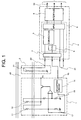
- a total temperature-error of the thermal-type flow measuring instrument is substantially equal to the measurement error due to the fluid temperature shown in Fig. 14.
- the measurement error depending upon the fluid temperature is corrected on the basis of the temperature of the fluid by the correction processing portion.
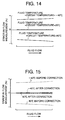
- the flow rate value after correction may contain substantially zero % of error due to temperature variation as shown in Fig. 15.
- Fig. 16 is a cross section of the thermal-type flow measuring instrument.
- the heating resistor 11 for detecting the flow rate and the reference resistor 12 to be a reference of the heating temperature of the heating resistor of the fluid are arranged within the auxiliary passage 43 formed integrally with the housing 51 receiving the electronic circuit 52 therein, and are electrically connected with the electronic circuit 52 via the terminal 53 and the wire 57.
- the electronic circuit 52 has CPU 71, an A/D converter 72, a memory 73, an interface 74 and so forth in addition to the control circuit 61, the reference voltage circuit 62 and the output characteristics adjusting circuit 63 to enable digital conversion within the electronic circuit and to perform arithmetic process.
- a method to separately arrange thermistor or the like can be considered.
- arithmetic process by CPU 71 is possible.
- the flow signal can be obtained, it becomes possible to obtain the signal corresponding to the fluid temperature by the arithmetic process of the value corresponding to the flow rate on the basis of the voltage at both ends of the reference voltage 12. Accordingly, by adjusting the measurement error depending upon the temperature variation of the fluid of the fluid signal digital converted by the A/D converter to be a constant rate irrespective of the flow rate as set forth above, the temperature-error can be reduced by correction by CPU 71 on the basis of the temperature of the fluid.
- the circuit substrate 52 since the circuit substrate 52 is provided within the main passage 42, the circuit temperature becomes closer to the fluid temperature than the case where the circuit substrate is located outside of the main passage. Therefore, it is also possible to make integrated correction of the temperature-error regarding that the fluid temperature and the circuit temperature are substantially the same.
- the circuit temperature is influenced by the external heat due to thermal conduction through the housing easier than the fluid, and since the circuit causes self-heating from the resistor, the element and so forth, the fluid and the circuit cannot become completely the same temperature. Therefore, the temperature characteristics of the foregoing circuit is desired to be adjusted so as to individually make the temperature-error substantially zero %.
- the flow rate signal arithmetically corrected by CPU 71 and the temperature signal of the fluid are output to the external devices from a connector terminal 75 via the interface 74.
- a numerical data such as coefficient for arithmetic process or so forth is stored in the memory 73. It is also possible to perform individual adjustment by rewriting the data in the memory 73.
- An air introduced into an engine cylinder 101 is controlled by a throttle valve 102 and an idle control valve 103.
- An intake air 110 is introduced into an air cleaner 104 from the outside, passes through a thermal-type flow measuring instrument 1 and a throttle body 115 via a filter 105, is introduced into the engine cylinder 101, and discharged as an exhaust gas 111 after combustion.
- an intake air temperature sensor 106 is arranged within the air cleaner 104.
- an air/fuel ratio sensor 107 is arranged within an exhaust pipe.
- a crank angle sensor 108 is arranged.
- a throttle angle sensor 109 is arranged.
- an air flow rate signal, an intake air temperature signal, an air/fuel ratio signal, a crank angle (engine speed) signal, a throttle angle signal are input.
- the control unit 112 outputs a fuel control signal of an injector 113 and an open degree signal of the idle control valve 103 for optimally controlling the engine on the basis of the input signals.
- the measurement error due to temperature variation of the fluid of the thermal-type flow measuring instrument can be easily corrected on the basis of the fluid temperature, it becomes possible to obtain the flow rate value with significantly reduced measurement error even under the environment where the temperature of the fluid and the temperature of the circuit are different, by adjusting the temperature characteristics of the circuit of the thermal-type flow measuring instrument so as not to cause measurement error.
- enhancement of precision of the system employing the thermal-type flow measuring instrument can be easily achieved without requiring significant variation of the system.
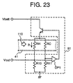
- FIG. 23 is a schematic circuit diagram of the thermal-type air flow measuring instrument.
- the drive circuit 91 of the thermal-type air flow measuring instrument is mainly composed of a bridge circuit and a feedback circuit.
- the heating resistor 3RH for measuring intake air flow, the temperature-sensitive resistors 4RC for compensating the intake air temperature, and resistors R10 and R11 are made to form a bridge circuit, and feedback operation is performed by operational amplifier OP1 and the output signal V2 corresponding to the air flow is put out by sending a heating current Ih to the heating resistor 3RH so as to maintain a constant temperature difference between the heating resistor 3RH and the temperature-sensitive resistor 4RC.
- the heating current Ih is made to be supplied more, In contrast, in case that the air flow is slower than that desired, as the amount of heat removed at the heating resistor 3RH is smaller, the heating current Ih is made to be reduced or small enough.
- FIG. 24 is a cross-sectional view of an example of the thermal-type air flow measuring instrument
- FIG. 25 is an outside drawings viewed from the upper stream (or left side in FIG. 23) of the example of the thermal-type air flow measuring instrument.
- the components of the thermal-type air flow measuring instrument there are a housing member 51 containing a circuit board 52 forming the drive circuit, and auxiliary passage composition member 56 formed with non-conductive materials.
- the heating resistor 11 for detecting the air flow and the temperature-sensitive resistor 21 for compensating the intake air temperature are arranged so as to be connected electrically to the circuit boards through the support member 53 composed of conductive materials, and thus, a single module in the thermal-type air flow measuring instrument is formed with the housing, the basic circuit board, the auxiliary passage, the heating resistor, the temperature-sensitive resistor and so on.
- a hole 85 is formed on the wide wall of the main passage 41 forming the intake air pipe, and the auxiliary passage part of the thermal-type air flow measuring instrument is inserted from outside into the hole 85, and the housing member 51 is fixed on the side wall of the auxiliary passage composition member mechanically with screws 87.
- the main passage composition member into which the auxiliary passage is inserted is a cylindrical tube, and its effective cross-sectional area with which the air flows in the main passage is almost identical at the entrance and exit of the auxiliary passage.
- a sealing material is inserted between the auxiliary passage composition member 56 and the main passage composition member in order to establish air resistance.
- FIG. 19 shows composition elements of the intake pipe in the internal combustion engine. Description is arranged from the upper stream of the air flow.
- the air cleaner is so defined with the air cleaner element 152 inserted between the air cleaner dirty-side case 150 and the air cleaner clean-side case 151.
- a part of the main passage is formed at the downstream of the air cleaner with the body member 160 used as a composition material of the thermal-type air flow measuring instrument, and the overall intake pipe is formed by linking the intake manifold 155 and the body member 160 with the air intake duct 158.
- ECU engine control unit
- ECU 100 has an input circuit part 101, an output circuit part 102, central processing unit (hereinafter referred to as CPU) 103 and memory 104 in its inside.
- CPU central processing unit
- memory 104 in its inside.
- the information exchange among the composition elements of ECU 100 is performed by the components marked with arrows 105a and 105b.
- the intake air temperature sensor 157 is mounted inside the intake air duct 158 for measuring the intake air temperature Ta, and the intake air flow in the intake air tube is measured by the heating resistor 11, both of which are sent to ECU 100.
- the measurement error due to temperature is corrected by CPU 103 referring to the correction value stored in the memory 104 and the air flow signal is estimated, and the control signal Tp corresponding to the obtained air flow signal for fuel injection operation is sent to the injector 154.
- the steps for calculating the intake air flow in the internal combustion engine is as shown in FIG. 18.
- the intake air flow flowing in the intake pipe is measured by the heating resistor 11 and the measured value is supplied as the output voltage Vo from the drive circuit module 161.
- the output voltage Vo is supplied to ECU 100
- the output voltage V0 is converted to VoD by digital signal processing in A/D converter 170.
- the digital signal VoD is further converted to the air flow by the converter 171, and is integrated by the integrator 173 for the time T.
- the engine revolution speed signal Ne is captured into ECU 100 and used for calculating the air flow Qa per a single cylinder in the computing unit 173.
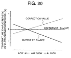
- FIG. 20 shows a graphical representation of the measurement error when the temperature of the circuit module part of the thermal-type air flow measuring instrument is 20°C and the intake air temperature is 80°C, with the reference value when both the temperature of the circuit module part of the thermal-type air flow measuring instrument and the intake air temperature are 20°C.
- the error at the lower flow is positive and the error at the higher flow is negative.
- the correction value is taken to be negative at the lower flow and to be positive at the higher flow in order to setoff the error.
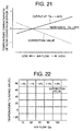
- FIG. 21 shows a graphical representation of the measurement error when both the temperature of the circuit module part of the thermal-type air flow measuring instrument and the intake air temperature is 20°C, with the reference value when only the intake air temperature is -30°C.
- the error at the lower flow is negative and the error at the higher flow is positive.
- the correction value is taken properly as shown in FIG. 20 in order to setoff the error.
- the correction calculation in the processing unit 174 shown in FIG. 18 is performed by reading the air flow and the intake air temperature and referring to the map containing correction values for intake air temperatures and intake air flows as shown in FIG. 22.
- thermal-type air flow measuring instruments including an intake air temperature sensor with its function extended are put into commercial production.
- microcomputers are embedded inside the thermal-type air flow measuring instrument, and the system architecture in which intake air temperature and intake air flow are measured by microprocessors and the intake air flow signal and the intake air flow signal after correcting the measurement error due to temperature changes are sent to ECU also brings the same effect as the system described above does.
- thermal-type air flow measuring instruments enabling to correct measurement errors due to temperature changes for wider range of air flow levels can be provided.
Landscapes
- Engineering & Computer Science (AREA)
- Physics & Mathematics (AREA)
- General Physics & Mathematics (AREA)
- Fluid Mechanics (AREA)
- Chemical & Material Sciences (AREA)
- Combustion & Propulsion (AREA)
- Mechanical Engineering (AREA)
- General Engineering & Computer Science (AREA)
- Measuring Volume Flow (AREA)
- Details Of Flowmeters (AREA)
Abstract
In flow detection by a thermal-type flow measuring
instrument (1), a flow rate value with reduced measurement error
due to temperature variation can be obtained even under
environment where a fluid temperature and a circuit temperature
are different.
A measurement error due to temperature variation of the
fluid of the thermal-type flow measuring instrument (1) can be
corrected on the basis of a temperature of the fluid by adjusting
the measurement error to be constant ratio irrespective of the
flow rate. On the other hand, a temperature characteristic of
the circuit is adjusted to be substantially zero %.
Description
The present invention relates to a thermal-type air flow
measuring instrument for measuring air flow taken into the
combustion engine for automotive vehicles and measurement-error
correcting apparatus.
In terms of environmental protection and resource saving,
more accurate combustion control is required for the engines
of automotive vehicles, and air flow meters capable of detecting
inlet air flow with high accuracy are desired. Such control
systems as employing thermal-type air flow measuring
instruments capable of measuring directly air mass flow are
mainstream today.
One of such measuring instruments is disclosed in
Japanese Patent Application Laid-Open No. 8-278178 (1996). The
measuring instrument is constructed so as to cancel a
temperature characteristic of the thermal-type flow measuring
instrument with a temperature characteristic of an electronic
circuit. In more detail, the thermal-type flow measuring
instrument disclosed therein corrects a dependence of a
measurement error depending upon variation of temperature,
relative to an air flow rate, by providing a flow rate dependence
to cancel the measurement error for the temperature
characteristics of a reference voltage generating circuit
incorporated in the thermal-type flow measuring instrument.
Another conventional measuring instrument is found in
Japanese Patent Laid-Open No. 60-100218. This prior art
discloses and teaches the correction method of temperature
characteristic of the thermal-type air flow measuring
instrument.
The former cancels the temperature-error contained in an
output of a bridge circuit formed with a heating resistor, a
temperature-sensitive resistor or the like to be caused
depending upon temperature variation of the fluid,
corresponding to the flow rate, by a temperature characteristic
of the electronic circuit. Accordingly, a problem is
encountered in that when a difference is caused between a
temperature of the fluid and the temperature of the electronic
circuit, the correction becomes not effective.
In the latter, the correction of the temperature
characteristic is established by adjusting the flow signal only
with a definite voltage value in responsive to the intake air
temperature without considering the measured air flow. In
practical conditions, however, the output signal corresponding
to the air flow is subject to the temperature of air flowing
in the heating resistor. This is caused by the following reasons.
The thermal-type air flow measuring instrument is
composed of a bridge circuit, in which the output voltage Vout
is defined by the formula 1.
Vout = √(A + B√(Q))
In the formula 1, constants A and B are constant with
respect to the air flow Q, but have temperature sensitive
characteristics. This is because temperature sensitive
characteristics of constants A and B are influenced by thermal
conductivity of air. In other words, the constants A and B
reflect changes in physical properties of air such as thermal
conductivity and kinematic viscosity. Thus, the differential
coefficient of the output of the bridge circuit with respect
to the temperature T, that is, dV/dT, is dependent upon air flow.
In addition, an influence of thermal conduction from the heating
resistor to the members on which the heating resistor is
supported is also another factor of air flow dependency. Thus,
in the prior art, there is such a problem that correction of
temperature characteristic can not be established for the wider
range of air flow and for the wider range of working temperature.
An object of the present invention is to improve the
temperature characteristic of the thermal-type air flow
measuring instrument for the wider range of air flow and for
the wider range of working temperature.
According to one aspect of the present invention, the
thermal-type flow measuring instrument is designed for
correcting a measurement error caused due to variation of a
temperature of a fluid of a thermal-type flow measuring
instrument on the basis of a temperature of the fluid, in which
a temperature-error of the thermal-type flow measuring
instrument is made a constant rate irrespective of a flow rate
so that the correction can be done unitarily on the basis of
only temperature signal.
According to another aspect of the present invention,
the intake air temperature in the intake pipe is measured and,
by means of micro-computers, used for correcting the measured
temperature so as to compensate the error for the air flow
dependency of the output temperature characteristic of the
thermal-type air flow measuring instrument.
Embodiments of the present invention will be discussed
hereinafter with reference to Figs. 1 to 25.
A construction of a control system employing a
temperature-error correcting apparatus as a typical embodiment
of the present invention is illustrated in Fig. 1.
The thermal-type flow measuring instrument 1 is
constructed by mounting a heating resistor 11 for detecting a
flow rate and a reference resistor 12 being a temperature-sensitive
resistor having a resistance value depending upon a
temperature of a fluid and being a reference to a heating
temperature of the heating resistor, to position within a fluid
passage 40, and forming a bridge circuit with the heating
resistor 11, the reference resistor 12 and other resistors 17
and 18. The heating resistor 11 is controlled so that a
temperature thereof is maintained higher than a temperature of
the fluid detected by the reference resistor 12 in a given
constant temperature. Accordingly, since a current is supplied
to the heating resistor 11 so that a heat amount equal to a
discharge amount to the fluid from the heating resistor 11 is
supplied, a current value flowing through the heating resistor
11 becomes a signal corresponding to the flow rate of the fluid.
This current is converted into a voltage by a resistor 17 as
a fixed resistor, adjusted by an output characteristics
adjusting circuit 14 for outputting a flow rate signal 15.
On the other hand, a fluid temperature detecting device
2 is designed by arranging a temperature-sensitive resistor 21,
such as a thermistor, within the fluid passage 40, which outputs
a resistance per se or a voltage value upon supplying a constant
current, as a temperature signal 22.
The foregoing fluid signal 15 and the temperature signal
22 are input to a control unit 4 together with other signals
31. Each of the input signals are converted into digital values
by an A/D converter 7 and processed in a microcomputer 9. Here,
since the flow rate signal is a voltage signal which is indeed
non-linear relative to the flow rate, the flow rate signal is
further converted into a linear flow rate value in a flow rate
converting portion 6 after conversion into the digital value,
and is corrected a measurement error due to temperature
variation of the fluid in a temperature correcting unit 3 to
be a flow rate signal to obtain a flow rate value with reduced
temperature-error. The flow rate signal after temperature
correction, the temperature signal and other signals are input
to the control portion 5 and control signals 32 for the engine
or equipment are output by the control unit 4 via an interface
8, such as a D/A converter or the like.
Next, as one embodiment of the thermal-type flow
measuring instrument to be employed in the present invention,
a construction of a thermal-type air flow measuring instrument
for measuring an intake air flow rate of an internal combustion
engine will be discussed with reference to a cross-section of
Fig. 2 and an external view as viewed from an upstream side of
Fig. 3.
The construction of the thermal-type air flow measuring
instrument is not required to be varied from the existing product
and here, only outline of the shown embodiment will be discussed.
The thermal-type flow measuring instrument is constructed with
a housing 51 receiving a circuit substrate 52 forming an
electronic circuit, an auxiliary passage forming member 56
fixed to the housing 51 and a body 41 to be the fluid passage.
The heating resistor 11 for detecting the flow rate and the
reference resistor 12 have conductive leads 54 on both ends and
are fixedly arranged within an auxiliary passage 43 by fixing
both ends of the conductive leads 54 on a terminal 53. The
terminal 53 is formed of a conductive material and is extended
into the inside of the housing 51 to be connected to the circuit
substrate 52 via a wire 57. An intake air 44 as an object for
measurement flows through the fluid passage defined in the body
41 as a main passage 42 and a part of the intake air is branched
to flow through the auxiliary passage 43 for obtaining a signal
corresponding to an air flow rate by the electronic circuit on
the basis of a heat radiation amount of the heating resistor
11. This signal is output to an external device via a connector
55.
A circuit diagram of an electronic circuit of the
thermal-type air flow measuring instrument is shown in Fig. 4.
The electronic circuit controls a heating temperature of the
heating resistor 11 and is mainly divided into a control circuit
61, in which a signal 19 corresponding to the flow rate can be
obtained, a temperature compensation circuit 62 for correcting
variation of output due to a temperature variation utilizing
temperature characteristics of a Zener diode 64 and a diode 65,
and an output characteristics adjusting circuit 63 for
adjusting zero level of the signal 19 corresponding to the flow
rate and a gain for adapting to a predetermined flow rate
characteristics.
A control circuit 61 is different in construction from
the single bridge circuit shown in Fig. 1 but is a circuit having
the same function as the single bridge as controlling the
temperature of the heating resistor 11 with respect to the air
temperature corresponding to the resistance value of the
reference resistor 12 so as to be higher than the latter in a
given constant temperature.
The temperature compensation circuit 62 is adapted to
obtain a reference voltage 68 of the output characteristics
adjusting circuit 63 having an arbitrary temperature
characteristics by adjusting a resistor 66 or a resistor 67
utilizing the temperature characteristics of the Zener diode
64 and the diode 65.
The output characteristics adjusting circuit 63 inputs
the signal 19 corresponding to the flow rate of the control
circuit 61 and obtains the flow rate signal 15 adapting to the
given flow rate characteristics by zero span adjustment by an
operational amplifier 69. Here, a voltage to be a reference
for zero point adjustment is adjusted to an arbitrary
temperature characteristics by the temperature compensation
circuit 62 to make it possible to adjust temperature
characteristics of the flow rate signal 15.
Figs. 5 to 7 show temperature characteristics of the flow
rate signal of the thermal-type flow measuring instrument in
the cases of conventional temperature-error adjustment for
measurement error at a temperature 80 °C and a temperature -40
°C with taking an error of the output characteristics as zero %
at 20 °C.
Fig. 5 shows measuring error when only temperature of the
fluid is varied to 80 °C or -40 °C by ignoring a resistance on
the circuit substrate and the temperature characteristics of
the element. The flow rate measurement error upon variation
of the temperature of the fluid is differentiated depending upon
flow rate shown in Fig. 5 and namely has a flow rate dependency
as varying physical value of the fluid, such as thermal
conductivity, kinematic viscosity and so forth, and as being
influenced by thermal conductivity of the lead or the like.
The measurement error can be adjusted by a resistor 13
connected with the reference resistor 12 in series.
Conventionally, the resistor 13 is set in an extent shown in
Fig. 5 so that the measurement error becomes close to zero over
the entire range of the flow rate.
On the other hand, the resistance on the circuit substrate
and the temperature characteristics of the element appear as
sum of the temperature characteristics of respective elements
and respective resistors, and can be adjusted by the temperature
compensation circuit as set forth above. The temperature
characteristics becomes a constant voltage irrespective of the
flow rate. However, the measurement error upon conversion into
the flow rate becomes large at low flow rate and small at high
flow rate. Accordingly, in order to cancel the flow rate
dependency of the measurement error shown in Fig. 5 as much as
possible, adjustment is performed to establish the temperature
characteristics with slight measurement error shown in Fig. 6.
As set forth above, when the fluid and the circuit are
indeed varied into the same temperature as set forth above, the
measurement error becomes as illustrated in Fig. 7. Since the
thermal-type flow measuring instrument measures the flow rate
by a heat radiation amount with taking the fluid temperature
as reference, the measurement error due to temperature
variation becomes smaller in comparison with other flow rate
measuring methods. The maximum error shown in Fig. 7 is
several % and conventionally not considered as significant
problem.
However, further precision has been required in the
recent years, to require reduction of the measurement error due
to temperature variation. The thermal-type flow measuring
instrument disclosed in Japanese Unexamined Patent Publication
No. Heisei 8-278178 discussed above as prior art provides one
of solution for this. This is designed for canceling the flow
rate dependency of the measurement error to be caused by
variation of the fluid temperature by providing flow amount
dependency for the temperature characteristics of the reference
voltage 68 to be output of the temperature compensation circuit
62.
Namely, when the conventional temperature-error
adjustment set forth above is performed, the measurement error
due to temperature variation of the fluid is the same (Fig. 8).
However, by enabling adjustment of the temperature
characteristics of the circuit substrate as shown in Fig. 9,
the measurement error when temperatures of the fluid and the
circuit are varied into the same temperature, becomes
substantially zero % as shown in Fig. 10.
However, even in the adjusting method disclosed in
Japanese Unexamined Patent Publication No. Heisei 8-278178,
while correction is effective when the temperature of the fluid
and the temperature of the circuit are substantially the same,
appropriate correction becomes impossible when a temperature
difference is caused therebetween. For example, in the
thermal-type air flow measuring instrument measuring the intake
air flow rate introduced into the engine of the automotive
vehicle, when a cool air is introduced in a condition where the
thermal-type air flow measuring instrument is mounted within
an engine room to subject a circuit portion to a heat from the
engine to be placed the circuit portion in heated condition,
or so forth, a situation that the circuit portion is heated up
to about 80 °C while the temperature of the intake air is about
20 °C, can be considered. Also, when the vehicle is driven into
ambient air in quite cold condition after sufficiently warming
up the engine, it is possible that while the circuit portion
is about 20 °C, the temperature of the intake air is about -40
°C.
Accordingly, in the former example, the temperature
characteristics of the circuit substrate becomes the
measurement error of the flow rate signal as is, and in the later
example, the measurement error due to temperature variation of
the intake air appears as the measurement error of the flow rate
signal as it is without being corrected by the temperature
characteristics of the circuit.
Therefore, the present invention is adapted to constantly
obtain the flow rate value suppressing the temperature-error
even in the case the temperature of the fluid and the temperature
of the circuit portion are different, by reducing the
measurement error to be caused due to temperature variation of
the fluid by correction on the basis of the temperature of the
fluid, and by adjusting the resistance of the circuit substrate
and the temperature characteristics of the element to make the
measurement error substantially zero % by the foregoing
temperature compensating circuit 62.
However, since the measurement error to be caused by
temperature variation of the fluid has flow rate dependency in
the conventional adjustment as set forth above, correction
which causes substantial load, such as deriving of a correction
coefficient from a map of the flow rate and the temperature
becomes necessary.
The present invention adjusts the thermal-type flow
measuring instrument to cause a constant measurement error
irrespective of the flow rate in order to avoid flow rate
dependency, without seeking for zero % of measurement error due
to temperature variation of the fluid, in order to perform the
correction quite easily. Conversely, without performing
adjustment canceling the measurement error due to temperature
variation of the fluid, the temperature characteristics of the
circuit may be so adjusted or set as not to cause the measurement
error (to be substantially zero %).
The adjustment of the measurement error due to
temperature variation of the fluid as set forth above, can be
performed by varying the resistance value of the resistor 13
arranged in series with the reference resistor 12, for example.
The measurement error when the temperature of the fluid is varied
from 20 °C to 80 °C or to -40 °C upon variation of the resistance
value of the resistor 13, is shown in comparison with the
conventional adjustment in Fig. 11. In a developed product
varied the resistance value of the resistor 13, the measurement
error due to the temperature variation of the fluid becomes minus
error at 80 °C but is in substantially constant rate irrespective
of the flow rate, and becomes positive error at -40 °C but is
in constant rate. The measurement error when the measurement
error due to temperature variation of the fluid has no flow rate
dependency and is flat, is different depending upon materials
forming the heating resistor 11 and the reference resistor 12
and the structures thereof. However, in view of performance
and reliability, it is difficulty to make the measurement error
flat at zero %. Therefore, it is the point of the present
invention to adjust the measurement error for avoiding the flow
rate dependency by varying the resistance value to be set easily
without pretending to make the measurement error to zero %.
On the other hand, the measurement error in the constant
ratio shows substantially linear correlation with the
temperature as shown in Fig. 12. Accordingly, correction of
the measurement error due to temperature variation of the fluid
can be done by obtaining a corrected error by multiplying a
temperature difference between the actually measured fluid
temperature and the reference temperature (20 °C in the shown
embodiment) with a gradient coefficient of Fig. 12, by
correcting the flow rate obtained from the thermal-type flow
measuring instrument in an amount corresponding to the error
to obtain the flow rate corrected the measurement error due to
the temperature variation of the fluid irrespective of the flow
rate. Thus, the present invention can make correction of the
measurement error due to temperature variation of the fluid by
a simple linear equation and is quite easy to perform correction
process to make the load of the processing portion smaller.
On the other hand, the temperature characteristics of the
circuit is adjusted to achieve substantially zero % of the
temperature characteristics of the circuit by the foregoing
reference voltage circuit 62, or, in the alternative, the
measuring error is made substantially zero % as shown in Fig.
13 by setting the temperature characteristics of the resistor
and the element to be little.
Accordingly, when the correcting portion of the
measurement error due to temperature variation of the fluid is
realized by the external processing unit or control unit of the
thermal-type flow measuring instrument, a total
temperature-error of the thermal-type flow measuring
instrument is substantially equal to the measurement error due
to the fluid temperature shown in Fig. 14. However, the
measurement error depending upon the fluid temperature is
corrected on the basis of the temperature of the fluid by the
correction processing portion. Thus, the flow rate value after
correction may contain substantially zero % of error due to
temperature variation as shown in Fig. 15. In this method,
since influences of the fluid temperature and the circuit
temperature are corrected independently, the flow rate with
reduced measurement error due to the temperature can be obtained
in an environment where the fluid temperature and the circuit
temperature are different as set forth above.
Next, concerning one embodiment of the thermal-type flow
measuring instrument having the correction processing portion
of the measurement error depending upon the fluid temperature
set forth above, discussion will be given with reference to Fig.
16 which is a cross section of the thermal-type flow measuring
instrument.
The heating resistor 11 for detecting the flow rate and
the reference resistor 12 to be a reference of the heating
temperature of the heating resistor of the fluid are arranged
within the auxiliary passage 43 formed integrally with the
housing 51 receiving the electronic circuit 52 therein, and are
electrically connected with the electronic circuit 52 via the
terminal 53 and the wire 57.
The electronic circuit 52 has CPU 71, an A/D converter
72, a memory 73, an interface 74 and so forth in addition to
the control circuit 61, the reference voltage circuit 62 and
the output characteristics adjusting circuit 63 to enable
digital conversion within the electronic circuit and to perform
arithmetic process. On the other hand, for temperature
measurement of the fluid, a method to separately arrange
thermistor or the like can be considered. However, it is also
possible to derive the fluid temperature from the voltages at
both ends of the reference resistor 12. Since the current
flowing through the reference resistor 12 is variable depending
upon the flow rare, the fluid temperature cannot be obtained
from the voltage at both ends of the reference resistor 12.
However, in the shown embodiment, arithmetic process by CPU 71
is possible. Also, since the flow signal can be obtained, it
becomes possible to obtain the signal corresponding to the fluid
temperature by the arithmetic process of the value
corresponding to the flow rate on the basis of the voltage at
both ends of the reference voltage 12. Accordingly, by
adjusting the measurement error depending upon the temperature
variation of the fluid of the fluid signal digital converted
by the A/D converter to be a constant rate irrespective of the
flow rate as set forth above, the temperature-error can be
reduced by correction by CPU 71 on the basis of the temperature
of the fluid.
On the other hand, in the shown embodiment, since the
circuit substrate 52 is provided within the main passage 42,
the circuit temperature becomes closer to the fluid temperature
than the case where the circuit substrate is located outside
of the main passage. Therefore, it is also possible to make
integrated correction of the temperature-error regarding that
the fluid temperature and the circuit temperature are
substantially the same. However, since the circuit temperature
is influenced by the external heat due to thermal conduction
through the housing easier than the fluid, and since the circuit
causes self-heating from the resistor, the element and so forth,
the fluid and the circuit cannot become completely the same
temperature. Therefore, the temperature characteristics of
the foregoing circuit is desired to be adjusted so as to
individually make the temperature-error substantially zero %.
Thus, the flow rate signal arithmetically corrected by
CPU 71 and the temperature signal of the fluid are output to
the external devices from a connector terminal 75 via the
interface 74. On the other hand, a numerical data, such as
coefficient for arithmetic process or so forth is stored in the
memory 73. It is also possible to perform individual adjustment
by rewriting the data in the memory 73. Finally, the
embodiment when the present invention is applied for
controlling the internal combustion engine will be discussed
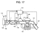
with reference to Fig. 17 which is an illustration showing a
construction of the internal combustion engine.
An air introduced into an engine cylinder 101 is
controlled by a throttle valve 102 and an idle control valve
103. An intake air 110 is introduced into an air cleaner 104
from the outside, passes through a thermal-type flow measuring
instrument 1 and a throttle body 115 via a filter 105, is
introduced into the engine cylinder 101, and discharged as an
exhaust gas 111 after combustion. On the other hand, within
the air cleaner 104, an intake air temperature sensor 106 is
arranged. Within an exhaust pipe, an air/fuel ratio sensor 107
is arranged. Also, in the engine, a crank angle sensor 108 is
arranged. Within a throttle body 115, a throttle angle sensor
109 is arranged. To a control unit 112, an air flow rate signal,
an intake air temperature signal, an air/fuel ratio signal, a
crank angle (engine speed) signal, a throttle angle signal are
input. The control unit 112 outputs a fuel control signal of
an injector 113 and an open degree signal of the idle control
valve 103 for optimally controlling the engine on the basis of
the input signals.
Here, by adjusting the measurement error to be caused by
variation of the intake air temperature of the thermal-type flow
measuring instrument 1 to be constant ratio irrespective of the
flow rate, correction becomes possible in the control unit 112
on the basis of the intake air temperature signal to obtain the
flow rate value reduced the measurement error due to intake air
temperature to permit higher precision engine control.
According to this embodiment of the present invention,
since the measurement error due to temperature variation of the
fluid of the thermal-type flow measuring instrument can be
easily corrected on the basis of the fluid temperature, it
becomes possible to obtain the flow rate value with
significantly reduced measurement error even under the
environment where the temperature of the fluid and the
temperature of the circuit are different, by adjusting the
temperature characteristics of the circuit of the thermal-type
flow measuring instrument so as not to cause measurement error.
Thus, enhancement of precision of the system employing the
thermal-type flow measuring instrument can be easily achieved
without requiring significant variation of the system.
Another embodiment of the present invention is now
described in detail with attached drawings.
At first, the basic principle of operations of the
thermal-type air flow measuring instrument is described. FIG.
23 is a schematic circuit diagram of the thermal-type air flow
measuring instrument. The drive circuit 91 of the thermal-type
air flow measuring instrument is mainly composed of a bridge
circuit and a feedback circuit. The heating resistor 3RH for
measuring intake air flow, the temperature-sensitive resistors
4RC for compensating the intake air temperature, and resistors
R10 and R11 are made to form a bridge circuit, and feedback
operation is performed by operational amplifier OP1 and the
output signal V2 corresponding to the air flow is put out by
sending a heating current Ih to the heating resistor 3RH so as
to maintain a constant temperature difference between the
heating resistor 3RH and the temperature-sensitive resistor 4RC.
For example, in case that the air flow is faster than that desired,
as the amount of heat removed at the heating resistor 3RH is
larger, the heating current Ih is made to be supplied more, In
contrast, in case that the air flow is slower than that desired,
as the amount of heat removed at the heating resistor 3RH is
smaller, the heating current Ih is made to be reduced or small
enough.
FIG. 24 is a cross-sectional view of an example of the
thermal-type air flow measuring instrument, and FIG. 25 is an
outside drawings viewed from the upper stream (or left side in
FIG. 23) of the example of the thermal-type air flow measuring
instrument.
As for the components of the thermal-type air flow
measuring instrument, there are a housing member 51 containing
a circuit board 52 forming the drive circuit, and auxiliary
passage composition member 56 formed with non-conductive
materials. In the auxiliary passage composition member 56, the
heating resistor 11 for detecting the air flow and the
temperature-sensitive resistor 21 for compensating the intake
air temperature are arranged so as to be connected electrically
to the circuit boards through the support member 53 composed
of conductive materials, and thus, a single module in the
thermal-type air flow measuring instrument is formed with the
housing, the basic circuit board, the auxiliary passage, the
heating resistor, the temperature-sensitive resistor and so on.
In addition, A hole 85 is formed on the wide wall of the main
passage 41 forming the intake air pipe, and the auxiliary passage
part of the thermal-type air flow measuring instrument is
inserted from outside into the hole 85, and the housing member
51 is fixed on the side wall of the auxiliary passage composition
member mechanically with screws 87. The main passage
composition member into which the auxiliary passage is inserted
is a cylindrical tube, and its effective cross-sectional area
with which the air flows in the main passage is almost identical
at the entrance and exit of the auxiliary passage. A sealing
material is inserted between the auxiliary passage composition
member 56 and the main passage composition member in order to
establish air resistance.
Next, detail aspect of the present invention is described
below.
At first, FIG. 19 shows composition elements of the intake
pipe in the internal combustion engine. Description is arranged
from the upper stream of the air flow. The air cleaner is so
defined with the air cleaner element 152 inserted between the
air cleaner dirty-side case 150 and the air cleaner clean-side
case 151. A part of the main passage is formed at the downstream
of the air cleaner with the body member 160 used as a composition
material of the thermal-type air flow measuring instrument, and
the overall intake pipe is formed by linking the intake manifold
155 and the body member 160 with the air intake duct 158.
Signals from various sensors in the combustion engine are
processed and used for engine control by the engine control unit
(hereinafter referred to as ECU) 100. Thus, error correction
of measured temperature in the thermal-type air flow measuring
instrument of the present invention is also performed in ECU
100.
The intake air temperature sensor 157 is mounted inside
the intake air duct 158 for measuring the intake air temperature
Ta, and the intake air flow in the intake air tube is measured
by the heating resistor 11, both of which are sent to ECU 100.
The measurement error due to temperature is corrected by CPU
103 referring to the correction value stored in the memory 104
and the air flow signal is estimated, and the control signal
Tp corresponding to the obtained air flow signal for fuel
injection operation is sent to the injector 154. The steps for
calculating the intake air flow in the internal combustion
engine is as shown in FIG. 18.
The intake air flow flowing in the intake pipe is measured
by the heating resistor 11 and the measured value is supplied
as the output voltage Vo from the drive circuit module 161. When
the output voltage Vo is supplied to ECU 100, the output voltage
V0 is converted to VoD by digital signal processing in A/D
converter 170. The digital signal VoD is further converted to
the air flow by the converter 171, and is integrated by the
integrator 173 for the time T. Next, the engine revolution speed
signal Ne is captured into ECU 100 and used for calculating the
air flow Qa per a single cylinder in the computing unit 173.
By combining the air flow Qa and the intake air temperature
signal Ta from the intake air temperature sensor, correction
of measurement error due to temperature change in the
thermal-type air flow measuring instrument of the present
invention is performed in the processing unit 174, and the
corrected signal is put out as the injection signal tp for the
injector 154 .
As for the error correction calculation, for example,
correction calculations shown in FIGS. 20 and 21 are performed.
FIG. 20 shows a graphical representation of the measurement
error when the temperature of the circuit module part of the
thermal-type air flow measuring instrument is 20°C and the
intake air temperature is 80°C, with the reference value when
both the temperature of the circuit module part of the
thermal-type air flow measuring instrument and the intake air
temperature are 20°C. The error at the lower flow is positive
and the error at the higher flow is negative. The correction
value is taken to be negative at the lower flow and to be positive
at the higher flow in order to setoff the error.
FIG. 21 shows a graphical representation of the
measurement error when both the temperature of the circuit
module part of the thermal-type air flow measuring instrument
and the intake air temperature is 20°C, with the reference value
when only the intake air temperature is -30°C. The error at the
lower flow is negative and the error at the higher flow is
positive. The correction value is taken properly as shown in
FIG. 20 in order to setoff the error.
So far, as the measurement error in the thermal-type air
flow measuring instrument changes for different flow and
temperature, the correction calculation in the processing unit
174 shown in FIG. 18 is performed by reading the air flow and
the intake air temperature and referring to the map containing
correction values for intake air temperatures and intake air
flows as shown in FIG. 22.
In the above description, though it is assumed that the
correction procedures are executed by ECU. In recent years,
thermal-type air flow measuring instruments including an intake
air temperature sensor with its function extended are put into
commercial production. For example, microcomputers are
embedded inside the thermal-type air flow measuring instrument,
and the system architecture in which intake air temperature and
intake air flow are measured by microprocessors and the intake
air flow signal and the intake air flow signal after correcting
the measurement error due to temperature changes are sent to
ECU also brings the same effect as the system described above
does.
According to this embodiment of the present invention,
thermal-type air flow measuring instruments enabling to correct
measurement errors due to temperature changes for wider range
of air flow levels can be provided.
In accordance with the foregoing disclosure, it is
readily apparent that the present invention is capable of many
variations. Detailed implementation can be derived from the
description contained herein by a person skilled in the art.
All such variations and modifications are considered to be
within the scope and spirit of the present invention as defined
by the following claims.
Claims (15)
- A temperature-error correcting apparatus of a thermal-type flow measuring instrument (1) characterized by adjusting a measurement error of a flow rate to be caused depending upon temperature variation of the fluid of the thermal-type flow measuring instrument (1) to be a constant ratio irrespective of a flow rate and unitarily correcting the measured value of the fluid depending upon a temperature of the fluid irrespective of the flow rate.
- A temperature-error correcting apparatus of a thermal-type flow measuring instrument (1) characterized by adjusting a measurement error of a flow rate to be caused depending upon temperature variation of the fluid of the thermal-type flow measuring instrument (1) to be a constant ratio irrespective of a flow rate and correcting said measurement error of the flow rate by a function of the measured value of the fluid and a fluid temperature.
- A temperature-error correcting apparatus of a thermal-type flow measuring instrument (1) characterized by adjusting a measurement error of a flow rate to be caused depending upon temperature variation of the fluid of the thermal-type flow measuring instrument (1) to be a constant ratio irrespective of a flow rate, deriving a correction coefficient of a measured value of the fluid as a linear function of a fluid temperature, and correcting said measurement error of the flow rate.
- A flow rate measuring system comprising:a thermal-type flow measuring instrument (1) adjusting a measurement error of a flow rate to be caused depending upon a temperature variation of the fluid of the thermal-type flow measuring instrument to be a constant ratio irrespective of the flow rate and outputting a signal corresponding to the flow rate,a temperature measuring device for detecting a temperature of the fluid and outputting a signal corresponding to the temperature, anda temperature-error correcting apparatus as set forth in claim 1, which inputs an output signal of said thermal-type flow measuring instrument and an output signal of said temperature measuring device and corrects a measurement error of the flow rate to be caused depending upon a temperature variation of the fluid of said thermal-type flow measuring instrument (1) on the basis of the temperature signal.
- The control system comprising a flow rate measuring system as set forth in claim 4 and means for performing control of an equipment or an engine depending upon the flow rate obtained by correcting the temperature-error of said thermal-type flow measuring instrument.
- A control system comprising a unit inputting an output signal of a thermal-type flow measuring instrument (1) and an output signal of a fluid temperature detecting device, and having a processing unit for outputting a flow rate value with corrected measurement error to be caused depending upon temperature variation of the fluid of said thermal-type flow measuring instrument (1), and a control unit outputting a control signal for an equipment or an engine depending upon the corrected fluid.
- A thermal-type flow measuring instrument characterized by adjusting a measurement error of a flow rate to be caused depending upon a temperature variation of the fluid to be constant ratio irrespective of the flow rate in order to perform temperature-error correction defined in claim 1.
- A thermal-type flow measuring instrument outputting a signal corresponding to a flow rate of a fluid on the basis of a heat radiation amount from a heating resistor (11) or a temperature of a resistor being heated, is characterized by integrating a flow rate measuring portion, a temperature measuring portion detecting a temperature of the fluid, and a processing portion having a function for correcting the measurement error of the flow rate to be caused depending upon temperature variation of the fluid by the temperature-error correcting apparatus as defined in claim 1.
- The thermal-type flow measuring instrument defined in claim 8 constructing a bridge circuit together with a heat generating (heating) resistor (11), deriving a temperature of the fluid by a reference resistor (12) to be a reference of a heating temperature of the heating resistor (11) which is a heat-sensitive resistor to have a resistance value corresponding to a temperature of the fluid and correcting a measurement error of the flow rate depending upon the temperature variation of the fluid on the basis of the measured temperature.
- The thermal-type flow measuring instrument defined in claim 8, wherein a measurement error of the flow rate to be caused depending upon the temperature variation of the fluid, of the signal corresponding to the flow rate input to said processing portion is adjusted to be a constant ratio irrespective of the flow rate to output a flow rate signal, in which the measurement error of the flow rate is corrected on the basis of a temperature of the fluid and a temperature signal corresponding to the temperature of the fluid.
- A thermal-type flow rate measuring instrument, a temperature-error correcting apparatus, a control system or a flow rate measuring system as defined in claim 1, wherein the measurement error of the flow rate to be caused depending upon the temperature variation of the fluid by a resistance value of a resistor arranged in series with a reference resistor (12) forming a bridge circuit together with a heating resistor (11) for flow rate measurement and to be a reference for a heating temperature of the heating resistor (11), is adjusted to be a constant ratio irrespective of the flow rate.
- A measurement-error correcting method of a thermal-type air flow measuring instrument (1) for measuring an intake air flow by sending an electric current for heating and detecting a heat release to an intake air, comprisinga step for measuring an intake air temperature; anda step for correcting said measurement error in responsive to an intake air temperature and an intake air flow.
- A measurement-error correcting method of a thermal-type air flow measuring instrument of Claim 12, wherein
output signal correcting method comprisesa step for preparing a map including an intake air flow value and an intake air temperature in said thermal-type air flow measuring instrument (1); anda step for correcting an take air flow signal corresponding to an intake air temperature by referring to an correction value stored in said map. - A control apparatus having a thermal-type air flow measuring instrument performing a correction method of Claim 1 or having a correction means for said correction method.
- A measurement-error correcting method of a thermal-type air flow measuring instrument (1) for measuring an intake air flow by sending an electric current for heating and detecting a heat release to an intake air, said method used for an internal combustion engine, comprisinga means for measuring an intake air temperature in an intake air tube of said internal combustion engine; anda means for correcting an average air flow in responsive to said intake air temperature.
Priority Applications (1)
| Application Number | Priority Date | Filing Date | Title |
|---|---|---|---|
| EP07003890A EP1793209A1 (en) | 1997-07-08 | 1998-07-03 | Thermal type flow measuring instrument and temperature-error correcting apparatus thereof |
Applications Claiming Priority (4)
| Application Number | Priority Date | Filing Date | Title |
|---|---|---|---|
| JP182065/97 | 1997-07-08 | ||
| JP9182065A JPH1123334A (en) | 1997-07-08 | 1997-07-08 | Heating resistor type apparatus for measuring air flow rate and method and apparatus for correcting measurement error thereof |
| JP18945097A JP3394426B2 (en) | 1997-07-15 | 1997-07-15 | Heating resistance type flow measurement device, temperature error correction system and correction device |
| JP189450/97 | 1997-07-15 |
Related Child Applications (1)
| Application Number | Title | Priority Date | Filing Date |
|---|---|---|---|
| EP07003890A Division EP1793209A1 (en) | 1997-07-08 | 1998-07-03 | Thermal type flow measuring instrument and temperature-error correcting apparatus thereof |
Publications (1)
| Publication Number | Publication Date |
|---|---|
| EP0890827A1 true EP0890827A1 (en) | 1999-01-13 |
Family
ID=26501005
Family Applications (2)
| Application Number | Title | Priority Date | Filing Date |
|---|---|---|---|
| EP07003890A Withdrawn EP1793209A1 (en) | 1997-07-08 | 1998-07-03 | Thermal type flow measuring instrument and temperature-error correcting apparatus thereof |
| EP98112397A Withdrawn EP0890827A1 (en) | 1997-07-08 | 1998-07-03 | Thermal type flow measuring instrument and temperature-error correcting apparatus thereof |
Family Applications Before (1)
| Application Number | Title | Priority Date | Filing Date |
|---|---|---|---|
| EP07003890A Withdrawn EP1793209A1 (en) | 1997-07-08 | 1998-07-03 | Thermal type flow measuring instrument and temperature-error correcting apparatus thereof |
Country Status (4)
| Country | Link |
|---|---|
| US (1) | US6230559B1 (en) |
| EP (2) | EP1793209A1 (en) |
| KR (1) | KR100491488B1 (en) |
| CN (2) | CN100347430C (en) |
Cited By (2)
| Publication number | Priority date | Publication date | Assignee | Title |
|---|---|---|---|---|
| EP1506377A1 (en) * | 2002-05-13 | 2005-02-16 | Delphi Technologies, Inc. | Optimized convection based mass airflow sensor circuit |
| EP2615431A1 (en) * | 2010-09-08 | 2013-07-17 | Hitachi Automotive Systems, Ltd. | Gas flow rate measurement device |
Families Citing this family (9)
| Publication number | Priority date | Publication date | Assignee | Title |
|---|---|---|---|---|
| JP2003240620A (en) * | 2002-02-20 | 2003-08-27 | Hitachi Ltd | Gas flow measuring device |
| JP4279130B2 (en) * | 2003-12-19 | 2009-06-17 | 株式会社日立製作所 | Heating resistor type fluid flow measuring device |
| US7107835B2 (en) * | 2004-09-08 | 2006-09-19 | Honeywell International Inc. | Thermal mass flow sensor |
| JP2006242748A (en) * | 2005-03-03 | 2006-09-14 | Hitachi Ltd | Heating resistor type air flow measurement apparatus and its measurement error correction method |
| JP4993311B2 (en) * | 2008-05-30 | 2012-08-08 | 株式会社デンソー | AIR FLOW MEASURING DEVICE, AIR FLOW CORRECTION METHOD, AND PROGRAM |
| CN102870059B (en) * | 2010-03-01 | 2015-08-12 | 普欧达加恩公司 | Flow control system and comprise the monitoring device for detecting airborne analysis thing of described flow control system |
| US10591332B2 (en) * | 2015-08-31 | 2020-03-17 | Hitachi Automotive Systems, Ltd. | Airflow meter |
| CN110186086B (en) * | 2019-05-19 | 2020-07-28 | 宁波方太厨具有限公司 | Series double-fan type range hood and flow control method thereof |
| CN117824771A (en) * | 2024-03-06 | 2024-04-05 | 成都睿宝电子科技有限公司 | Automatic temperature compensation circuit and compensation method for thermal flowmeter |
Citations (3)
| Publication number | Priority date | Publication date | Assignee | Title |
|---|---|---|---|---|
| JPS60100218A (en) | 1983-11-04 | 1985-06-04 | Hitachi Ltd | Power circuit |
| US4683858A (en) * | 1985-06-17 | 1987-08-04 | Nippondenso Co., Ltd. | Apparatus for controlling engine |
| EP0240637A1 (en) | 1986-04-11 | 1987-10-14 | Purdue Research Foundation | Electrical technique for correcting bridge type mass air flow rate sensor errors resulting from ambient temperature variations |
Family Cites Families (2)
| Publication number | Priority date | Publication date | Assignee | Title |
|---|---|---|---|---|
| US4987549A (en) * | 1989-11-13 | 1991-01-22 | General Motors Corporation | Temperature compensated flowmeter techniques |
| JPH08278178A (en) * | 1995-04-03 | 1996-10-22 | Hitachi Ltd | Thermal type air flow meter |
-
1998
- 1998-07-03 EP EP07003890A patent/EP1793209A1/en not_active Withdrawn
- 1998-07-03 EP EP98112397A patent/EP0890827A1/en not_active Withdrawn
- 1998-07-07 KR KR10-1998-0027205A patent/KR100491488B1/en not_active IP Right Cessation
- 1998-07-07 CN CNB2004100877965A patent/CN100347430C/en not_active Expired - Fee Related
- 1998-07-07 CN CNB981156886A patent/CN1222759C/en not_active Expired - Fee Related
- 1998-07-08 US US09/111,767 patent/US6230559B1/en not_active Expired - Lifetime
Patent Citations (4)
| Publication number | Priority date | Publication date | Assignee | Title |
|---|---|---|---|---|
| JPS60100218A (en) | 1983-11-04 | 1985-06-04 | Hitachi Ltd | Power circuit |
| US4581929A (en) * | 1983-11-04 | 1986-04-15 | Hitachi, Ltd. | Air flow meter circuit with temperature compensation circuit |
| US4683858A (en) * | 1985-06-17 | 1987-08-04 | Nippondenso Co., Ltd. | Apparatus for controlling engine |
| EP0240637A1 (en) | 1986-04-11 | 1987-10-14 | Purdue Research Foundation | Electrical technique for correcting bridge type mass air flow rate sensor errors resulting from ambient temperature variations |
Cited By (4)
| Publication number | Priority date | Publication date | Assignee | Title |
|---|---|---|---|---|
| EP1506377A1 (en) * | 2002-05-13 | 2005-02-16 | Delphi Technologies, Inc. | Optimized convection based mass airflow sensor circuit |
| EP1506377A4 (en) * | 2002-05-13 | 2006-04-19 | Delphi Tech Inc | Optimized convection based mass airflow sensor circuit |
| EP2615431A1 (en) * | 2010-09-08 | 2013-07-17 | Hitachi Automotive Systems, Ltd. | Gas flow rate measurement device |
| EP2615431A4 (en) * | 2010-09-08 | 2014-07-23 | Hitachi Automotive Systems Ltd | Gas flow rate measurement device |
Also Published As
| Publication number | Publication date |
|---|---|
| US6230559B1 (en) | 2001-05-15 |
| CN1222759C (en) | 2005-10-12 |
| KR100491488B1 (en) | 2005-09-02 |
| EP1793209A1 (en) | 2007-06-06 |
| CN100347430C (en) | 2007-11-07 |
| KR19990013637A (en) | 1999-02-25 |
| CN1210972A (en) | 1999-03-17 |
| CN1605733A (en) | 2005-04-13 |
Similar Documents
| Publication | Publication Date | Title |
|---|---|---|
| US7269999B2 (en) | Thermal airflow meter | |
| EP0240637A1 (en) | Electrical technique for correcting bridge type mass air flow rate sensor errors resulting from ambient temperature variations | |
| US7201048B2 (en) | Measuring device for a flow sensor, in particular an air mass sensor for internal combustion engines and method for measuring air flows | |
| US4502325A (en) | Measurement of mass airflow into an engine | |
| US5635635A (en) | Method and apparatus for detecting the intake air quantity of an engine | |
| EP0890827A1 (en) | Thermal type flow measuring instrument and temperature-error correcting apparatus thereof | |
| US5107812A (en) | Thermal type intake air flow measuring instrument and internal combustion engine control apparatus using this measuring instrument | |
| KR20020081398A (en) | Thermal air flowmeter | |
| US5419187A (en) | Air flow rate meter and detection method | |
| EP1657532A1 (en) | Thermal mass flow sensor | |
| WO2003098162A1 (en) | Optimized convection based fluid flow sensor circuit | |
| US4688425A (en) | Direct-heated flow measuring apparatus having film resistor | |
| JPH11337382A (en) | Heat generating resistor type air flow rate measuring apparatus | |
| US7213455B2 (en) | Thermal type gas flow measuring instrument | |
| KR100687960B1 (en) | Control system for internal combustion engine comprising a sensor and an interface for digitising measurement values | |
| US5211056A (en) | Thermal type intake air flow measuring instrument | |
| JP3394426B2 (en) | Heating resistance type flow measurement device, temperature error correction system and correction device | |
| JP2957769B2 (en) | Thermal air flow meter and engine controller | |
| JP3105609B2 (en) | Heating resistor type air flow meter | |
| JP3095322B2 (en) | Thermal air flow detector | |
| JP2944890B2 (en) | Thermal air flow detector | |
| KR820002255B1 (en) | Air flow rate measuring apparatus | |
| EP1014046A1 (en) | Thermal air flow meter | |
| JP2875948B2 (en) | Intake air flow rate detection device | |
| JPH1048016A (en) | Heating resistor-type air flow measuring device and fuel injection controlling system for internal-combustion |
Legal Events
| Date | Code | Title | Description |
|---|---|---|---|
| PUAI | Public reference made under article 153(3) epc to a published international application that has entered the european phase |
Free format text: ORIGINAL CODE: 0009012 |
|
| AK | Designated contracting states |
Kind code of ref document: A1 Designated state(s): DE FR GB IT |
|
| AX | Request for extension of the european patent |
Free format text: AL;LT;LV;MK;RO;SI |
|
| 17P | Request for examination filed |
Effective date: 19981210 |
|
| AKX | Designation fees paid |
Free format text: DE FR GB IT |
|
| 17Q | First examination report despatched |
Effective date: 20060627 |
|
| STAA | Information on the status of an ep patent application or granted ep patent |
Free format text: STATUS: THE APPLICATION IS DEEMED TO BE WITHDRAWN |
|
| 18D | Application deemed to be withdrawn |
Effective date: 20100202 |