EP0890260B1 - Controlling vcr by using personal computer - Google Patents
Controlling vcr by using personal computer Download PDFInfo
- Publication number
- EP0890260B1 EP0890260B1 EP97915900A EP97915900A EP0890260B1 EP 0890260 B1 EP0890260 B1 EP 0890260B1 EP 97915900 A EP97915900 A EP 97915900A EP 97915900 A EP97915900 A EP 97915900A EP 0890260 B1 EP0890260 B1 EP 0890260B1
- Authority
- EP
- European Patent Office
- Prior art keywords
- signal
- personal computer
- vcr
- video
- control signal
- Prior art date
- Legal status (The legal status is an assumption and is not a legal conclusion. Google has not performed a legal analysis and makes no representation as to the accuracy of the status listed.)
- Expired - Lifetime
Links
Images


Classifications
-
- H—ELECTRICITY
- H04—ELECTRIC COMMUNICATION TECHNIQUE
- H04N—PICTORIAL COMMUNICATION, e.g. TELEVISION
- H04N5/00—Details of television systems
- H04N5/76—Television signal recording
- H04N5/765—Interface circuits between an apparatus for recording and another apparatus
-
- H—ELECTRICITY
- H04—ELECTRIC COMMUNICATION TECHNIQUE
- H04N—PICTORIAL COMMUNICATION, e.g. TELEVISION
- H04N5/00—Details of television systems
- H04N5/76—Television signal recording
- H04N5/78—Television signal recording using magnetic recording
- H04N5/782—Television signal recording using magnetic recording on tape
-
- H—ELECTRICITY
- H04—ELECTRIC COMMUNICATION TECHNIQUE
- H04N—PICTORIAL COMMUNICATION, e.g. TELEVISION
- H04N7/00—Television systems
- H04N7/08—Systems for the simultaneous or sequential transmission of more than one television signal, e.g. additional information signals, the signals occupying wholly or partially the same frequency band, e.g. by time division
- H04N7/087—Systems for the simultaneous or sequential transmission of more than one television signal, e.g. additional information signals, the signals occupying wholly or partially the same frequency band, e.g. by time division with signal insertion during the vertical blanking interval only
- H04N7/088—Systems for the simultaneous or sequential transmission of more than one television signal, e.g. additional information signals, the signals occupying wholly or partially the same frequency band, e.g. by time division with signal insertion during the vertical blanking interval only the inserted signal being digital
- H04N7/0887—Systems for the simultaneous or sequential transmission of more than one television signal, e.g. additional information signals, the signals occupying wholly or partially the same frequency band, e.g. by time division with signal insertion during the vertical blanking interval only the inserted signal being digital for the transmission of programme or channel identifying signals
Definitions
- the present invention relates to a system for controlling a video cassette recorder from a personal computer.
- US-A-4706121 discloses a system for controlling a television receiver so as to permit user selection of broadcast programs from schedule information.
- the schedule information is received by an FM receiver, decoded and demodulated and applied to a data processor.
- a user remote control supplies user selection inputs to the data processor and the data processor selects programs from the schedule information based on the user inputs.
- the schedule information for the selected programs is stored in a memory and is used by the data processor to control a programmable T.V. tuner so as to provide the broadcast signals for the selected programs to the T.V. receiver at the time of broadcast.
- the system disclosed by this reference may also be used to control a VCR for unattended recording of the selected programs.
- EP-A-0607734 discloses a system for automatic programming a video cassette recorder utilizing a data processing system. Programming information is extracted from a broadcast television system and displayed on a monitor of a personal computer. The information may be selected by a user and instructions for control of the VCR by an infra-red device.
- Personal computers have been developed and marketed with the capability to receive and display publicly broadcasted television signals.
- the broadcasted video images may be displayed in a separate window that allows the user to watch television while performing other operations on the personal computer.
- It may be desirable to store the television signals in a disk drive of the computer. Analog video signals, once digitized, typically require a large amount of memory space on the disk. For this reason, storing television signals on the disk drive is generally undesirable.
- VCR video cassette recorder
- Video cassette recorders are typically located in a different room than the personal computer. Therefore a system that controls a video cassette recorder through a personal computer would require routing a plurality of cables between the VCR and the computer. Routing cables can be both expensive and time consuming. It would be desirable to provide a system that allows a personal computer to remotely control the operation of a video cassette recorder.
- the present invention is a system that allows a personal computer to remotely control the operation of a video cassette recorder (VCR).
- the system includes a radio frequency (RF) transmitter connected to a personal computer.
- the computer is programmed to generate a first VCR control signal that is transmitted by the RF transmitter to a RF receiver located within a transceiver base unit.
- the transceiver base unit transmits a second VCR control signal to the VCR using an infrared (IR transmitter) in response to the first VCR control signal.
- the VCR control signals include commands to record, stop, play, etc. the video cassette recorder.
- the first VCR control signal can be transmitted in response to a control data signal that is inserted into the vertical blanking interval of a publicly broadcasted video signal that is received and decoded by the personal computer.
- the control data signal may contain program information which is used to trigger the transmission of the first VCR control signal.
- FIG. 1 shows a video cassette recording system 10 of the present invention.
- the system includes a broadcaster 12, a personal computer 14 and a video cassette recorder (VCR) 16.
- the video cassette recorder 16 receives a video cassette tape 18.
- the VCR 16 can read and write video signals onto the tape 18.
- the VCR 16 has internal circuitry to perform start, stop, play, rewind, forward, etc. functions as is known in the art.
- the VCR 16 has a remote receiver 20 which can receive VCR control signals that control the various start, record, play, stop, etc. functions of the recorder 16.
- the remote receiver 20 may receive input signals in the infrared (IR) waveband.
- the video cassette recorder 16 is typically connected to a television receiver 21 which may also have a remote receiver (not shown).
- the personal computer 14 includes a central processing unit (CPU) 22, a memory device 24 and a mass storage device such as a disk drive 26.
- the personal computer 14 may be connected to a printer 27.
- the computer 14 generates the first VCR control signal that is transmitted by a transmitter 28.
- the transmitter 28 may be a RF device.
- the first VCR control signal may be received by the receiver 30 of a transceiver base unit 32.
- the transceiver 32 may have a transmitter 34 that transmits a second VCR control signal in response to the reception of the first VCR control signal.
- the second VCR control signal may be received by the remote receiver 20 of the VCR.
- the transmitter 28 and transceiver receiver 30 are RF devices.
- the transceiver transmitter 34 and VCR receiver 20 are preferably IR devices.
- the transceiver 32 can also generate control signals to control the television receiver 21, including signals to change the channels of the television 21.
- the broadcaster 12 may include a video signal source 36 that generates a video signal and a data signal source 38 that generates a data signal.
- the broadcaster 12 may also include a vertical blanking interval (VBI) inserter 40 that inserts the data signal into the vertical blanking interval of the video signal.
- the inserted video signal is transmitted by a transmitter 42.
- the VBI inserter 40 may be a unit sold by Norpak Corp. of Ottawa, Ontario, Canada under the model number TDS-3 or similar ones from Wavephone of Canada or EEG of New York.
- the data source 38 may generate data that corresponds to the program being broadcasted from the video source 36.
- the data signal may include a title and a description of the broadcasted program.
- XDS a standard commonly referred to as XDS which defines the information which can be inserted into a vertical blanking interval of a video signal.
- the personal computer 14 is connected to a television receiver 44 which can receive the inserted video signal transmitted by the broadcaster 12.
- the receiver 44 contains a tuner that can tune to various broadcasted channels.
- the receiver 44 is connected to a vertical blanking interval decoder 46 which separates the data signal from the video signal.
- the video signal may be connected to a NTSC decoder 48 which decoded the decoded video signal to a computer monitor 50.
- the separated data signal is provided to the CPU 22 for further processing.
- the format of the inserter 40 may have different application layers, including a transport layer 60, a network layer 62 and a datalink layer 64 which convert the program information into a serial data stream that can be inserted into the vertical blanking interval by the VBI inserter 40.
- the transport layer 60 provides an interface with the data source 38.
- the network layer 62 packetizes the data.
- the datalink layer 64 serializes the packeted data for serial transmission to the VBI inserter 40.
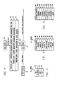
- the data is provided to the VBI inserter in a Vt_Frame 70 shown in Figure 3.
- the Vt_Frame 70 includes a start frame field STX 72, a data packet field Vt_Packet 74, a check field CRC 76 and an end of frame character ETX 78.
- the Vt_Packet 74 is formatted as shown in Figure 4.
- the nPacketProtocal field 80 is a byte-length field which identifies the packet as one supported by the protocol.
- the nVersion field 82 specifies the type of inserter that is transmitting the packet.
- the nChanID field 84 is an integer value which provides the channel number of the packet in the serialized bitstream.
- the nMessageID field 86 specifies the message number of the channel on which the packet is transmitted.
- the nPacketID field 88 defines the number of packets in a particular message.
- the fMorePackets field 90 specifies whether there are any more packets in the message.
- the fReserved field 92 is reserved for further use.
- the length of the data is specified in the nDataSize field 94.
- the nData field 96 contains the data.
- the data is typically provided to the inserter 40 by the data source in the format shown in Figure 5.
- the nMessageProtocal field 98 is a byte length field which identifies the type of transmission being provided.
- the nVersion field 100 identifies the version of the protocol.
- the flsHint field 102 indicates that the data is to precede an event such as a television program.
- the flsUPdate field 104 indicates whether the information is updating transmitted information.
- the fReserved field 106 is unused and reserved for later use.
- the field nDataSize 108 specifies the number of bytes in the data field.
- the nOpcode field 110 define a particular operation to be performed with the data. For example, the operation may be a read memory command.
- the fReserved2 field 112 is not used and the bData field 114 contains the data.
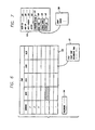
- the personal computer 14 may contain a program that creates a graphical user interface program map 120 which is display by the computer monitor 50.
- the map 120 may be divided into a plurality of blocks that correspond to TIME and CHANNEL listings.
- the data signals inserted into the vertical blanking interval of the video signal may have program information that is displayed by the map 120.
- the broadcaster 12 may periodically insert data that provides the title and a short description of the present broadcasted program plus three subsequent programs, and so forth and so on.
- the personal computer 14 receives the program information and displays the title and description within the appropriate block.
- the personal computer can continuously update the static map 120 with broadcasted program information.
- the user can record a program(s) by selecting the appropriate box(es) on the map 120.
- the user can request a recording of a program on channel 2 that begins at 9:00 PM by selecting the box that corresponds to channel 2 and 9:00 PM.
- the program then stores the selection in memory.
- the personal computer At a predetermine time interval before 9:00 PM the personal computer generates VCR control signals to initiate a recording sequence of the program with the video cassette recorder.
- the first VCR control signals can be generated when new program information is detected in the vertical blanking interval, indicating that a new program has begun.
- the selected programs can be highlighted to indicate which programs will be recorded. Each highlighted program may have a "drop box" 122 which list the title, start, recording time, etc. of the selected program.
- the drop box 122 may be reviewed by entering a command or double selecting the map block.
- the program may have a configuration dialog 124 which contains a user identification (ID) field 126, a video cassette tape ID field 128, a tape length field 130, a recording speed field 132 and a Program Guide command 134.
- the static map 120 can be viewed by selecting the Program Guide Command 134.
- the dialog 124 may also have a VCR type command 136 with a separate drop box 138 that list the various manufacturing brands of video cassette recorders.
- the personal computer may have a look up table that contains the various control signal protocols for the different VCRs. The correct control signals can be generated when the user selects the make of the VCR in the drop box 138.
- the dialog may contain a Print Label field 140 which when selected prints a label of the programs that are recorded.
- the dialog may also include a Parental Lock-in field 142 which when selected prevents recording or viewing of a program unless a valid password is entered.
- the static map 120 may include a password field 144 that receives a password.
- the program may include a dialog 150 that list the various programs that were recorded.
- the dialog 150 may have a plurality of tape slots 152 that each contain the start time and title of a recorded program.
- a recorded program can be viewed by the user by selecting a tape slot 152.
- the computer In response to the selection of a tape slot 152, the computer generates VCR control signals to rewind the video cassette tape and then forward the tape (if required) to the location of the selected program.
- the dialog 150 may also have a Record command 154 that allows the user to select which part of the tape will be used for further recording. For example, the user may select PROGRAM 2 to be the slot in the tape where the next recorded program is to be stored.
- the personal computer compares the length of the next recorded program selected by the user with the selected tape slot to insure that the tape slot has enough space to store the entire program. If the next selected program exceeds the time interval of the tape slot, the program may provide a message to request the user to select another tape slot or another tape.
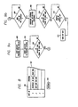
- Figures 9a-b show a flowchart of a process that records a program.
- the user has selected the appropriate entries in the configuration dialog, including the selection of program that is to be recorded.
- the personal computer sets the tuner of the receiver 44 to the selected channel in block 202.
- decision block 204 the process determines whether the present time equals the start time of the selected program.
- the start time that is compared with the present time may be slightly before the program start time to allow for the generation of control signals and the power, tuning, etc. of the VCR.
- decision block 206 determines whether the vertical blanking data has changed.
- a change in the vertical blanking data is an indication that a new program has started. If the vertical blanking data has changed, the personal computer generates VCR control signals to turn on the VCR, select the appropriate channel and record the program in block 208.
- decision block 210 compares the present time with the end time of the selected program. When the times are equal the personal computer generates control signals to stop the VCR and store the program information in the dialog 150 in block 212.
- the program determines whether the VCR should be turned off, factoring whether another program has been selected for recording and the time interval until the broadcasting of the selected program in decision block 214. If the VCR is to be turned off, the personal computer generates control signals to turn off the VCR. The process then proceeds back to block 200.
- Figures 10a-b show a flowchart of a personal computer process that scans the broadcasted channels to retrieve program information from the vertical blanking interval.
- the tuner of the personal computer is set to a first channel in processing block 250.
- the personal computer determines whether the channel is set in decision block 252. If the channel is set a timer is started in block 254. The value of the timer is compared to a threshold time value in decision block 256. If the value of the timer is less than the threshold value then the process proceeds to decision block 258 to determine if there is data in the vertical blanking interval. If there is vertical blanking data, the data is stored in the personal computer in block 260. If there is no data the process proceeds back to block 256.
- the process proceeds to decision block 262 to determine whether there is vertical blanking interval data. If there is vertical blanking data the data is stored in block 260. After the vertical blanking data is stored, or if there is no data as determined in block 262, the tuner is incremented one channel in block 264. The process proceeds to decision block 266 which determines whether the channel is equal to a threshold value. If the incremented channel is equal to the threshold value the channel is decremented back to the original channel in block 268. After block 264 and 266 the process proceeds to block 250.
- the information stored in block 260 is used to fill the static map 120 of the program and may also be used to trigger a recording of a program.
Description
Claims (10)
- A system for remotely programming a video cassette recorder that has a remote receiver, the video cassette recorder being coupled to a television receiver, comprising:a personal computer located external to the video cassette recorder, the personal computer includes a computer monitor to display a graphical user interface, and a first decoder to receive a broadcast signal and separate a control data signal having program information from the broadcast signal, the personal computer to display the program information on the graphical user interface to allow user selection of the program information, the personal computer includes a second decoder which decodes the broadcast signal so that a broadcast video image can be displayed on the computer monitor, the personal computer further includes a wireless transmitter to transmit a first VCR control signal in response to the user selection of the program information, wherein said first VCR control signal is an rf signal; anda transceiver located external to the personal computer and the video cassette recorder, the transceiver to wirelessly receive the first VCR control signal from the personal computer and, responsive thereto, to wirelessly transmit a second VCR control signal to the remote receiver of the video cassette recorder to control the video cassette recorder, wherein said second VCR control signal is an infrared control signal.
- The system as recited in claim 1, wherein said personal computer transmits said first VCR control signal in response to detecting a new program information in a vertical blanking interval.
- The system as recited in claim 2, wherein said control data signal includes program information regarding a publicly broadcasted program.
- The system as recited in claim 3, wherein said personal computer compares said program information with previous program information, and said personal computer transmits said first VCR control signal if said program information does not match said previous program information.
- The system as recited in claim 1, wherein the transmitter comprises a radio frequency transmitter that transmits said first VCR control signal, and wherein the transceiver includes a radio frequency receiver that receives said first VCR control signal.
- The system as recited in claim 5, wherein said transceiver includes an infrared transmitter that generates said second VCR control signal.
- The system as recited in claim 1, wherein said first and second VCR control signals include a start command to start recording a video signal with the video cassette recorder, and a stop command which terminates the recording of the video signal.
- The system as recited in claim 1, wherein said first and second VCR control signals include a play command to start playing a recorded video signal with the video cassette recorder, and a stop command which terminates the playing of the video signal.
- A system for remotely programming a video cassette recorder that has a remote receiver, the video cassette recorder being coupled to a television receiver, comprising:personal computer means located external to the video cassette recorder, the personal computer means for (i) displaying a graphical user interface on a computer monitor, (ii) receiving a broadcast signal and separating a control data signal having program information from the broadcast signal, (iii) displaying the program information on the graphical user interface to allow user selection of the program information, (iv) decoding the broadcast signal so that a broadcast video image can be displayed on the computer monitor, and (v) wirelessly transmitting a first VCR control signal in response to the user selection of the program information, wherein the first VCR control signal is an rf signal; andtransceiver means located external to the personal computer means and the video cassette recorder, the transceiver means for wirelessly receiving the first VCR control signal from the personal computer means and, responsive thereto, for wirelessly transmitting a second VCR control signal to the remote receiver of the video cassette recorder to control the video cassette recorder, wherein said second VCR control signal is an infrared control signal.
- A method for recording a transmitted video signal on a video cassette recorder that is coupled to a television receiver utilizing a personal computer, comprising:displaying a graphical user interface on a computer monitor;entering data into a field of the graphical user interface;inserting a control data signal into a video signal;transmitting the video and control data signals;receiving the video and control data signals;separating the control data signal which has program information from the video signal;displaying the program information on the graphical user interface on the computer monitor to allow user selection of the program information along with entered data;decoding the transmitted video signal;displaying the video signal on the computer monitor,comparing the separated control data with the entered data;transmitting wirelessly a first VCR control signal from a personal computer located external to the VCR to a transceiver located external to the personal computer and the VCR, in response to the separated control data signal if the control data signal matches the entered data, wherein said first VCR control signal is an rf signal;receiving said first VCR control signal by said transceiver,transmitting wirelessly a second VCR control signal from said transceiver to the video cassette recorder, in response to said first VCR control signal from the personal computer, wherein said second VCR control signal is an infrared control signal, and wherein said first and second VCR control signals provide a control command to control the video cassette recorder; and,recording the video signal in response to the first VCR control signal.
Applications Claiming Priority (3)
| Application Number | Priority Date | Filing Date | Title |
|---|---|---|---|
| US623585 | 1990-12-07 | ||
| US08/623,585 US6195501B1 (en) | 1996-03-28 | 1996-03-28 | Computer control of a video cassette recorder using wireless communication and a vertical blanking interval triggering |
| PCT/US1997/003763 WO1997036422A1 (en) | 1996-03-28 | 1997-03-10 | Controlling vcr by using personal computer |
Publications (3)
| Publication Number | Publication Date |
|---|---|
| EP0890260A1 EP0890260A1 (en) | 1999-01-13 |
| EP0890260A4 EP0890260A4 (en) | 2000-07-05 |
| EP0890260B1 true EP0890260B1 (en) | 2003-07-09 |
Family
ID=24498638
Family Applications (1)
| Application Number | Title | Priority Date | Filing Date |
|---|---|---|---|
| EP97915900A Expired - Lifetime EP0890260B1 (en) | 1996-03-28 | 1997-03-10 | Controlling vcr by using personal computer |
Country Status (6)
| Country | Link |
|---|---|
| US (1) | US6195501B1 (en) |
| EP (1) | EP0890260B1 (en) |
| AU (1) | AU2321097A (en) |
| CA (1) | CA2250925C (en) |
| DE (1) | DE69723427T2 (en) |
| WO (1) | WO1997036422A1 (en) |
Families Citing this family (82)
| Publication number | Priority date | Publication date | Assignee | Title |
|---|---|---|---|---|
| US6769128B1 (en) | 1995-06-07 | 2004-07-27 | United Video Properties, Inc. | Electronic television program guide schedule system and method with data feed access |
| US6323911B1 (en) | 1995-10-02 | 2001-11-27 | Starsight Telecast, Inc. | System and method for using television schedule information |
| US8850477B2 (en) | 1995-10-02 | 2014-09-30 | Starsight Telecast, Inc. | Systems and methods for linking television viewers with advertisers and broadcasters |
| US6388714B1 (en) | 1995-10-02 | 2002-05-14 | Starsight Telecast Inc | Interactive computer system for providing television schedule information |
| US5940073A (en) | 1996-05-03 | 1999-08-17 | Starsight Telecast Inc. | Method and system for displaying other information in a TV program guide |
| WO1998010589A1 (en) * | 1996-09-03 | 1998-03-12 | Starsight Telecast, Inc. | Schedule system with enhanced recording capability |
| US20030005463A1 (en) * | 1999-09-30 | 2003-01-02 | Douglas B Macrae | Access to internet data through a television system |
| US20030066085A1 (en) | 1996-12-10 | 2003-04-03 | United Video Properties, Inc., A Corporation Of Delaware | Internet television program guide system |
| BRPI9812104B1 (en) | 1997-07-21 | 2016-12-27 | Guide E Inc | method for navigating an interactive program guide |
| US6141488A (en) | 1997-09-05 | 2000-10-31 | United Video Properties, Inc. | Program guide system for recording television programs |
| TW392402B (en) | 1997-10-22 | 2000-06-01 | Hitachi Ltd | Method for using audio and video machine and audio and video machine system |
| JPH11252471A (en) * | 1998-03-03 | 1999-09-17 | Matsushita Electric Ind Co Ltd | Center device and terminal equipment for broadcasting program and program information |
| CN1867068A (en) | 1998-07-14 | 2006-11-22 | 联合视频制品公司 | Client-server based interactive television program guide system with remote server recording |
| US6668158B1 (en) * | 1998-07-16 | 2003-12-23 | Sony Corporation | Control method, control apparatus, data receiving and recording method, data receiver and receiving method |
| AR020608A1 (en) | 1998-07-17 | 2002-05-22 | United Video Properties Inc | A METHOD AND A PROVISION TO SUPPLY A USER REMOTE ACCESS TO AN INTERACTIVE PROGRAMMING GUIDE BY A REMOTE ACCESS LINK |
| ES2342593T3 (en) * | 1998-07-17 | 2010-07-09 | United Video Properties, Inc. | INTERACTIVE GUIDE SYSTEM OF TELEVISION PROGRAMS THAT HAVE MULTIPLE DEVICES INSIDE A HOUSE. |
| JP2000050186A (en) * | 1998-07-24 | 2000-02-18 | Toshiba Video Products Japan Kk | Recorder |
| US6898762B2 (en) | 1998-08-21 | 2005-05-24 | United Video Properties, Inc. | Client-server electronic program guide |
| DE69935766T2 (en) * | 1998-09-14 | 2007-12-27 | Sony Corp. | Information processing apparatus, information processing method and storage medium |
| US6865746B1 (en) | 1998-12-03 | 2005-03-08 | United Video Properties, Inc. | Electronic program guide with related-program search feature |
| US6438751B1 (en) | 1999-02-18 | 2002-08-20 | Joseph F. Voyticky | Integrated television and internet information system |
| US6637028B1 (en) | 1999-02-18 | 2003-10-21 | Cliq Distribution, Inc. | Integrated television and internet information system |
| CA2335629C (en) * | 1999-04-26 | 2010-02-16 | Sony Corporation | Image recording system |
| WO2001011867A2 (en) * | 1999-08-09 | 2001-02-15 | Gemstar Development Corporation | Method and apparatus for programming of a vcr recording |
| US6993134B1 (en) * | 1999-08-09 | 2006-01-31 | Koninklijke Philips Electronics N.V. | Key exchange via a portable remote control device |
| WO2001046869A2 (en) | 1999-12-10 | 2001-06-28 | United Video Properties, Inc. | Systems and methods for coordinating interactive and passive advertisement and merchandising opportunities |
| AUPQ506000A0 (en) * | 2000-01-13 | 2000-02-03 | Right Hemisphere Pty Limited | Video recorder with improved control system |
| US7895610B1 (en) * | 2000-01-18 | 2011-02-22 | Koninklijke Philips Electronics N.V. | System and method for displaying information on the screen of a user interface device under the control of a digital audio playback device |
| JP4750996B2 (en) | 2000-02-01 | 2011-08-17 | ユナイテッド ビデオ プロパティーズ インク | Method and system for forced advertising |
| FR2805699A1 (en) * | 2000-02-25 | 2001-08-31 | Thomson Multimedia Sa | Display system for digital TV broadcasts includes recording system for retaining sequenced information for user selection |
| US7979881B1 (en) | 2000-03-30 | 2011-07-12 | Microsoft Corporation | System and method for identifying audio/visual programs to be recorded |
| US20010054060A1 (en) * | 2000-06-16 | 2001-12-20 | Fillebrown Lisa A. | Personal wireless network |
| DE60135567D1 (en) | 2000-10-11 | 2008-10-09 | United Video Properties Inc | SYSTEMS AND METHOD FOR PROVISION OF DATA STORAGE IN SERVER IN A MEDIA-ON-REQUEST DELIVERY SYSTEM |
| US6651253B2 (en) * | 2000-11-16 | 2003-11-18 | Mydtv, Inc. | Interactive system and method for generating metadata for programming events |
| WO2002056536A1 (en) * | 2001-01-09 | 2002-07-18 | Telefonaktiebolaget Lm Ericsson | Method and system for bonding two bluetooth devices |
| KR100896725B1 (en) * | 2001-02-21 | 2009-05-11 | 유나이티드 비디오 프로퍼티즈, 인크. | Method and system for recording series programming |
| US20030206719A1 (en) * | 2002-04-23 | 2003-11-06 | Jim Bumgardner | Storage Management for a Video Recorder |
| US7774816B2 (en) * | 2002-04-23 | 2010-08-10 | Rovi Technologies Corporation | Conflict manager for a video recorder |
| GB2400508B (en) * | 2002-12-18 | 2006-10-25 | Chris Skelton | Automatic recording device for use with set top boxes |
| US7493646B2 (en) | 2003-01-30 | 2009-02-17 | United Video Properties, Inc. | Interactive television systems with digital video recording and adjustable reminders |
| US8116611B2 (en) * | 2003-02-10 | 2012-02-14 | Aptiv Digital, Inc. | Tuner sharing video recorder system architecture |
| US20040177371A1 (en) * | 2003-03-07 | 2004-09-09 | Rami Caspi | System and method for integrated communications center |
| US7536708B2 (en) * | 2003-03-07 | 2009-05-19 | Siemens Communications, Inc. | System and method for context-based searching and control of an integrated communications center |
| US20040177375A1 (en) * | 2003-03-07 | 2004-09-09 | Rami Caspi | System and method for short message service control of an integrated communications center |
| US20040174863A1 (en) * | 2003-03-07 | 2004-09-09 | Rami Caspi | System and method for wireless remote control of a digital personal media stream manager |
| US7519073B2 (en) * | 2003-03-07 | 2009-04-14 | Siemens Communications, Inc. | System and method for instant messaging control of an integrated communications center |
| US7787749B2 (en) * | 2003-03-07 | 2010-08-31 | Siemens Enterprise Communications, Inc. | System and method for voice portal control of an integrated communications center |
| US7761898B2 (en) * | 2003-03-07 | 2010-07-20 | Siemens Enterprise Communications, Inc. | System and method for e-mail control of an integrated communications center |
| US7525975B2 (en) * | 2003-03-07 | 2009-04-28 | Rami Caspi | System and method for integrated audio stream manager |
| JP2004297545A (en) * | 2003-03-27 | 2004-10-21 | Matsushita Electric Ind Co Ltd | Remote control apparatus |
| US20040213557A1 (en) * | 2003-04-23 | 2004-10-28 | Pioneer Digital Technologies, Inc. | Non-hierarchical interface screens for use in a video recorder |
| US7984468B2 (en) | 2003-11-06 | 2011-07-19 | United Video Properties, Inc. | Systems and methods for providing program suggestions in an interactive television program guide |
| US9021529B2 (en) * | 2004-07-15 | 2015-04-28 | Microsoft Technology Licensing, Llc | Content recordation techniques |
| US8806533B1 (en) | 2004-10-08 | 2014-08-12 | United Video Properties, Inc. | System and method for using television information codes |
| US7657526B2 (en) | 2006-03-06 | 2010-02-02 | Veveo, Inc. | Methods and systems for selecting and presenting content based on activity level spikes associated with the content |
| US8316394B2 (en) | 2006-03-24 | 2012-11-20 | United Video Properties, Inc. | Interactive media guidance application with intelligent navigation and display features |
| WO2008042267A2 (en) * | 2006-09-29 | 2008-04-10 | United Video Properties, Inc. | Systems and methods for a modular media guidance dashboard application |
| US8832742B2 (en) | 2006-10-06 | 2014-09-09 | United Video Properties, Inc. | Systems and methods for acquiring, categorizing and delivering media in interactive media guidance applications |
| US8209424B2 (en) | 2006-12-20 | 2012-06-26 | United Video Properties, Inc. | Systems and methods for providing remote access to interactive media guidance applications |
| US7801888B2 (en) | 2007-03-09 | 2010-09-21 | Microsoft Corporation | Media content search results ranked by popularity |
| US8418206B2 (en) | 2007-03-22 | 2013-04-09 | United Video Properties, Inc. | User defined rules for assigning destinations of content |
| US8087047B2 (en) | 2007-04-20 | 2011-12-27 | United Video Properties, Inc. | Systems and methods for providing remote access to interactive media guidance applications |
| US8107977B2 (en) | 2007-09-07 | 2012-01-31 | United Video Properties, Inc. | Cross-platform messaging |
| US20090165049A1 (en) | 2007-12-19 | 2009-06-25 | United Video Properties, Inc. | Methods and devices for presenting and interactive media guidance application |
| US8252911B2 (en) * | 2008-02-12 | 2012-08-28 | Pacific Biosciences Of California, Inc. | Compositions and methods for use in analytical reactions |
| US8989561B1 (en) | 2008-05-29 | 2015-03-24 | Rovi Guides, Inc. | Systems and methods for alerting users of the postponed recording of programs |
| US8601526B2 (en) | 2008-06-13 | 2013-12-03 | United Video Properties, Inc. | Systems and methods for displaying media content and media guidance information |
| US10063934B2 (en) | 2008-11-25 | 2018-08-28 | Rovi Technologies Corporation | Reducing unicast session duration with restart TV |
| US20100333151A1 (en) * | 2009-06-30 | 2010-12-30 | Gemstar Development Corporation | Cross platform entertainment architecture |
| US9166714B2 (en) | 2009-09-11 | 2015-10-20 | Veveo, Inc. | Method of and system for presenting enriched video viewing analytics |
| US9014546B2 (en) | 2009-09-23 | 2015-04-21 | Rovi Guides, Inc. | Systems and methods for automatically detecting users within detection regions of media devices |
| US9201627B2 (en) | 2010-01-05 | 2015-12-01 | Rovi Guides, Inc. | Systems and methods for transferring content between user equipment and a wireless communications device |
| US9204193B2 (en) | 2010-05-14 | 2015-12-01 | Rovi Guides, Inc. | Systems and methods for media detection and filtering using a parental control logging application |
| US9167196B2 (en) | 2010-05-19 | 2015-10-20 | Rovi Guides, Inc. | Systems and methods for trimming recorded content using a media guidance application |
| WO2012094564A1 (en) | 2011-01-06 | 2012-07-12 | Veveo, Inc. | Methods of and systems for content search based on environment sampling |
| US9854318B2 (en) | 2011-06-06 | 2017-12-26 | Rovi Guides, Inc. | Systems and methods for sharing interactive media guidance information |
| US8949901B2 (en) | 2011-06-29 | 2015-02-03 | Rovi Guides, Inc. | Methods and systems for customizing viewing environment preferences in a viewing environment control application |
| US8805418B2 (en) | 2011-12-23 | 2014-08-12 | United Video Properties, Inc. | Methods and systems for performing actions based on location-based rules |
| US9218122B2 (en) | 2011-12-29 | 2015-12-22 | Rovi Guides, Inc. | Systems and methods for transferring settings across devices based on user gestures |
| US9253262B2 (en) | 2013-01-24 | 2016-02-02 | Rovi Guides, Inc. | Systems and methods for connecting media devices through web sockets |
| US9674563B2 (en) | 2013-11-04 | 2017-06-06 | Rovi Guides, Inc. | Systems and methods for recommending content |
| US9288521B2 (en) | 2014-05-28 | 2016-03-15 | Rovi Guides, Inc. | Systems and methods for updating media asset data based on pause point in the media asset |
Family Cites Families (15)
| Publication number | Priority date | Publication date | Assignee | Title |
|---|---|---|---|---|
| US4963994A (en) * | 1981-12-14 | 1990-10-16 | Levine Michael R | VCR programmer |
| US4706121B1 (en) * | 1985-07-12 | 1993-12-14 | Insight Telecast, Inc. | Tv schedule system and process |
| US5056070A (en) * | 1988-06-06 | 1991-10-08 | Sony Corporation | Timer programming apparatus |
| US4977455B1 (en) * | 1988-07-15 | 1993-04-13 | System and process for vcr scheduling | |
| US5307173A (en) * | 1988-12-23 | 1994-04-26 | Gemstar Development Corporation | Apparatus and method using compressed codes for television program record scheduling |
| KR900010504A (en) * | 1988-12-31 | 1990-07-07 | 안시환 | Home automation method and apparatus using video tape recorder |
| US5293357A (en) * | 1990-09-10 | 1994-03-08 | The Superguide Corporation | Method and apparatus for controlling a television program recording device |
| US5488409A (en) * | 1991-08-19 | 1996-01-30 | Yuen; Henry C. | Apparatus and method for tracking the playing of VCR programs |
| JP3334166B2 (en) * | 1992-06-30 | 2002-10-15 | ソニー株式会社 | VTR |
| KR0165246B1 (en) * | 1992-09-04 | 1999-03-20 | 윤종용 | Sunscribed recording method and device by character input |
| EP0607734A3 (en) | 1993-01-21 | 1994-08-10 | International Business Machines Corporation | Programming of a video cassetterecorder |
| US5515173A (en) * | 1993-03-05 | 1996-05-07 | Gemstar Developement Corporation | System and method for automatically recording television programs in television systems with tuners external to video recorders |
| JP3353370B2 (en) * | 1993-04-02 | 2002-12-03 | ソニー株式会社 | Remote control device for recording / reproducing device and remote control method |
| US5481296A (en) * | 1993-08-06 | 1996-01-02 | International Business Machines Corporation | Apparatus and method for selectively viewing video information |
| US5557724A (en) * | 1993-10-12 | 1996-09-17 | Intel Corporation | User interface, method, and apparatus selecting and playing channels having video, audio, and/or text streams |
-
1996
- 1996-03-28 US US08/623,585 patent/US6195501B1/en not_active Expired - Lifetime
-
1997
- 1997-03-10 WO PCT/US1997/003763 patent/WO1997036422A1/en active IP Right Grant
- 1997-03-10 EP EP97915900A patent/EP0890260B1/en not_active Expired - Lifetime
- 1997-03-10 AU AU23210/97A patent/AU2321097A/en not_active Abandoned
- 1997-03-10 DE DE69723427T patent/DE69723427T2/en not_active Expired - Fee Related
- 1997-03-10 CA CA002250925A patent/CA2250925C/en not_active Expired - Fee Related
Also Published As
| Publication number | Publication date |
|---|---|
| DE69723427D1 (en) | 2003-08-14 |
| CA2250925A1 (en) | 1997-10-02 |
| US6195501B1 (en) | 2001-02-27 |
| CA2250925C (en) | 2001-08-21 |
| AU2321097A (en) | 1997-10-17 |
| DE69723427T2 (en) | 2004-05-27 |
| EP0890260A1 (en) | 1999-01-13 |
| EP0890260A4 (en) | 2000-07-05 |
| WO1997036422A1 (en) | 1997-10-02 |
Similar Documents
| Publication | Publication Date | Title |
|---|---|---|
| EP0890260B1 (en) | Controlling vcr by using personal computer | |
| WO1997036422A9 (en) | Controlling vcr by using personal computer | |
| US6341195B1 (en) | Apparatus and methods for a television on-screen guide | |
| US5661526A (en) | Broadcast signal receiver and tape recorder and, method of detecting additional information channel | |
| US5659367A (en) | Television on/off detector for use in a video cassette recorder | |
| US4641205A (en) | Television system scheduler with on-screen menu type programming prompting apparatus | |
| EP0337336B1 (en) | Applications for information transmitted in the vertical retrace interval of a television signal | |
| US5640484A (en) | Switch for automatic selection of television signal sources for delivery of television guide data | |
| KR100283916B1 (en) | Video tape recorder | |
| KR100630942B1 (en) | Television signal processing device having a data block address memory for autonomously determining television program information | |
| JPH0721619A (en) | Video recording management device | |
| US5895123A (en) | Information recording/reproduction apparatus for reproducing picture and audio signals in synchronization | |
| US6208800B1 (en) | Recording apparatus, recording system, and recording method | |
| US6289170B1 (en) | Video device with an electronic program guide decoder | |
| EP1290880A2 (en) | An enhanced television system | |
| EP0393556B1 (en) | Improvements in applications for information transmitted in the vertical retrace interval of a television signal | |
| US20020010918A1 (en) | Apparatus and methods for a television on-screen guide | |
| EP0715464A2 (en) | Broadcasting signal receivers | |
| JPH0562283A (en) | Automatic learning video recording device in magnetic recording and reproducing device | |
| JP3387166B2 (en) | Broadcast signal receiver | |
| GB2262419A (en) | Cable television receiving apparatus | |
| JP3287479B2 (en) | Television broadcasting method and television receiver | |
| JPH10208327A (en) | Method for program reservation recording and device therefor | |
| US6907185B1 (en) | Method and apparatus for reserve-recording a viewing broadcast program | |
| JPH10224705A (en) | Channel selection device and method for setting its guide channel |
Legal Events
| Date | Code | Title | Description |
|---|---|---|---|
| PUAI | Public reference made under article 153(3) epc to a published international application that has entered the european phase |
Free format text: ORIGINAL CODE: 0009012 |
|
| 17P | Request for examination filed |
Effective date: 19981027 |
|
| AK | Designated contracting states |
Kind code of ref document: A1 Designated state(s): DE FR GB |
|
| RIC1 | Information provided on ipc code assigned before grant |
Free format text: 7H 04N 5/76 A, 7H 04N 5/782 B |
|
| A4 | Supplementary search report drawn up and despatched |
Effective date: 20000517 |
|
| AK | Designated contracting states |
Kind code of ref document: A4 Designated state(s): DE FR GB |
|
| 17Q | First examination report despatched |
Effective date: 20020205 |
|
| GRAH | Despatch of communication of intention to grant a patent |
Free format text: ORIGINAL CODE: EPIDOS IGRA |
|
| GRAH | Despatch of communication of intention to grant a patent |
Free format text: ORIGINAL CODE: EPIDOS IGRA |
|
| GRAA | (expected) grant |
Free format text: ORIGINAL CODE: 0009210 |
|
| AK | Designated contracting states |
Designated state(s): DE FR GB |
|
| REG | Reference to a national code |
Ref country code: GB Ref legal event code: FG4D |
|
| REF | Corresponds to: |
Ref document number: 69723427 Country of ref document: DE Date of ref document: 20030814 Kind code of ref document: P |
|
| ET | Fr: translation filed | ||
| PLBE | No opposition filed within time limit |
Free format text: ORIGINAL CODE: 0009261 |
|
| STAA | Information on the status of an ep patent application or granted ep patent |
Free format text: STATUS: NO OPPOSITION FILED WITHIN TIME LIMIT |
|
| 26N | No opposition filed |
Effective date: 20040414 |
|
| PGFP | Annual fee paid to national office [announced via postgrant information from national office to epo] |
Ref country code: DE Payment date: 20090327 Year of fee payment: 13 |
|
| PGFP | Annual fee paid to national office [announced via postgrant information from national office to epo] |
Ref country code: FR Payment date: 20090317 Year of fee payment: 13 |
|
| PGFP | Annual fee paid to national office [announced via postgrant information from national office to epo] |
Ref country code: GB Payment date: 20090403 Year of fee payment: 13 |
|
| GBPC | Gb: european patent ceased through non-payment of renewal fee |
Effective date: 20100310 |
|
| REG | Reference to a national code |
Ref country code: FR Ref legal event code: ST Effective date: 20101130 |
|
| PG25 | Lapsed in a contracting state [announced via postgrant information from national office to epo] |
Ref country code: FR Free format text: LAPSE BECAUSE OF NON-PAYMENT OF DUE FEES Effective date: 20100331 |
|
| PG25 | Lapsed in a contracting state [announced via postgrant information from national office to epo] |
Ref country code: DE Free format text: LAPSE BECAUSE OF NON-PAYMENT OF DUE FEES Effective date: 20101001 |
|
| PG25 | Lapsed in a contracting state [announced via postgrant information from national office to epo] |
Ref country code: GB Free format text: LAPSE BECAUSE OF NON-PAYMENT OF DUE FEES Effective date: 20100310 |