EP0885697A1 - Razor providing pivoting and swivelling razor head support - Google Patents
Razor providing pivoting and swivelling razor head support Download PDFInfo
- Publication number
- EP0885697A1 EP0885697A1 EP98304199A EP98304199A EP0885697A1 EP 0885697 A1 EP0885697 A1 EP 0885697A1 EP 98304199 A EP98304199 A EP 98304199A EP 98304199 A EP98304199 A EP 98304199A EP 0885697 A1 EP0885697 A1 EP 0885697A1
- Authority
- EP
- European Patent Office
- Prior art keywords
- razor
- engagement arms
- axis
- engagement
- shaving
- Prior art date
- Legal status (The legal status is an assumption and is not a legal conclusion. Google has not performed a legal analysis and makes no representation as to the accuracy of the status listed.)
- Granted
Links
Images


Classifications
-
- B—PERFORMING OPERATIONS; TRANSPORTING
- B26—HAND CUTTING TOOLS; CUTTING; SEVERING
- B26B—HAND-HELD CUTTING TOOLS NOT OTHERWISE PROVIDED FOR
- B26B21/00—Razors of the open or knife type; Safety razors or other shaving implements of the planing type; Hair-trimming devices involving a razor-blade; Equipment therefor
- B26B21/08—Razors of the open or knife type; Safety razors or other shaving implements of the planing type; Hair-trimming devices involving a razor-blade; Equipment therefor involving changeable blades
- B26B21/14—Safety razors with one or more blades arranged transversely to the handle
- B26B21/22—Safety razors with one or more blades arranged transversely to the handle involving several blades to be used simultaneously
- B26B21/222—Safety razors with one or more blades arranged transversely to the handle involving several blades to be used simultaneously with the blades moulded into, or attached to, a changeable unit
- B26B21/225—Safety razors with one or more blades arranged transversely to the handle involving several blades to be used simultaneously with the blades moulded into, or attached to, a changeable unit the changeable unit being resiliently mounted on the handle
Definitions
- the present invention is directed to a razor which supports a razor head and, more particularly, to a razor which permits a razor head to swivel and pivot relative to a shaving stroke.
- Shaving systems have been proposed which provide a razor head having a housing with relatively movable skin engaging elements, including a guard element, one or more blades and a cap member. It has also been suggested to provide various degrees of movement of the entire razor head relative to the razor which supports the razor head.
- the various embodiments of the present invention are directed to improvements in razors which permit a razor head to swivel and pivot in response to forces encountered during shaving.
- 5,535,518 discloses a four bar linkage system which allows pivoting and swivelling, but does not show springs or biasing elements for returning the razor head to a neutral position after the removal of shaving forces.
- the present invention is directed to improvements to shaving systems which allow a razor head to swivel and pivot relative to a razor during shaving.
- a razor as defined in Claim 1.
- a shaving system as defined in Claim 2.
- a razor as defined in Claim 4.
- a razor as defined in Claim 15.
- Various embodiments of the present invention are directed to razors adapted to support a razor head during shaving while permitting the razor head to move relative to the razor in response to forces encountered during shaving.
- the various embodiments described herein allow a razor head to swivel and also to pivot about an axis normal to a central axis of the razor and normal to an imaginary axis defined by the points of attachment of the razor to a razor head.
- Preferred embodiments of the present invention restrict the movement of the engagement arms of a razor head to paths substantially parallel to a central longitudinal axis of the operative part of the razor. In this manner, no lateral component of blade movement is permitted along an axis defined by the engagement points of the engagement arms.
- the engagement arms are also preferably restricted to movement within a single plane.
- the various embodiments provide shaving systems with improved blade-to-skin contact independent of wrist movement, while simultaneously reducing the amount of lateral movement of the razor head relative to the shaving path.
- the term "razor head” is meant to include cartridges adapted to be connected to a separate razor as well as the operative cutting portion of a disposable razor wherein the handle and cutting portion are formed as a single unit.
- razors are provided with a plunger for returning a swivelling razor head to a predetermined position when shaving forces have been removed, a pair of engagement arms for providing pivoting motion, and an actuator for moving the engagement portions of the engagement arms closer together for loading and unloading a razor head.
- a first biasing member e.g. a coil spring
- a second biasing member e.g. a torsion spring
- both the first biasing member and the second biasing member urge the actuator rearwardly to the "at rest” position.
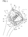
- Figure 1 is a top perspective view with sections removed of one embodiment of the present invention.
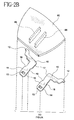
- Figures 2A and 2B collectively show an exploded bottom view of the razor shown in Figure 1.
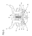
- Figures 3-5 are top views showing the engagement arms of the razor shown in Figure 1 in various positions.
- Figure 1 is a top view of one razor of the present invention with sections removed. This illustrated embodiment is designed to engage a razor head (not shown) with a pair of engagement arms 10a, 10b which permit the razor head to swivel and pivot relative to the razor in response to forces encountered during shaving.
- the illustrated razor head of the present invention comprises a pair of engagement arms 10, a plunger 30, an actuator 50, a compression spring 60, a torsion spring 65, a top cover 70, a base 80, and a slidable cross beam 90.
- the fork members (engagement arms 10) are pivotally connected to the cross beam 90 and slidably guided by the base 80 and top cover 70.
- the plunger 30 is provided to return a razor head which has swivelled to a predetermined position while the engagement arms are also biased to return the razor head to a predetermined position, preferably normal to the central longitudinal axis of the razor, after shaving forces have been removed.
- the engagement arms 10 comprise engagement pins 12 adapted to be received within recesses of a razor head in a manner which permits the razor head to swivel about an axis substantially parallel to an imaginary axis defined by pins 12.
- the plunger 30 comprises a plunger base 35 having a pair of opposing slots 37 adapted to slidingly receive the sidewalls 75 of a cut out in top cover 70. Slots 37 in plunger base 35 thereby guide plunger 30 forwardly and rearwardly relative to cover 70 along a central longitudinal axis L of the razor. (See Fig.1)
- the forward portion of plunger 30 which engages a ramped surface of a razor head extends through an opening 72 of cover 70.
- Rearward movement of the plunger relative to cover 70 can be limited by a pair of detents (not shown).
- Plunger 30 is forwardly biased and comprises a pin 33 which engages the forward end of coil spring 60.
- the rearward end of coil spring 60 engages a pin 53 of actuator 50.
- This arrangement advantageously utilizes a single coil spring to provide forward biasing forces on plunger 30 and rearward biasing forces on an actuator 50 described in further detail below.
- the razors of the present invention advantageously permit pivoting of the entire razor head on the razor.
- the term “pivoting” is used to define movement of the razor head about an imaginary axis normal to an axis defined by pins 12 of engagement arms 10 and also normal to a central, longitudinal axis L of the razor defined by the forward-rearward movement of plunger 30.
- pivoting of a razor head is distinguished from the "rocking" motion of previously suggested systems which included a lateral component relative to the direction of the shaving stroke.
- the engagement arms are maintained in a path which is substantially parallel to the central longitudinal axis L of the razor by guide walls of the top cover 70 and base 80 which slidingly engage sidewalls of the engagement members.
- a first pair of outer, guide walls 74 of top cover 70 engage rear outer sidewalls 14 of engagement arms 10.
- a pair of downwardly depending ridges 86 of bottom cover 80 slidingly engage rear inner sidewalls 16 of engagement arms 10.
- the outer surfaces of abutments 77 of top cover 70 slidingly engage the inner, forward surfaces 17 of engagement arms 10. Therefore, engagement arms 10 are guided forwardly and rearwardly along paths substantially parallel to the central longitudinal axis L of the razor within their range of motion experienced during shaving.
- the forward portions of cover sidewalls 74 are each provided with inwardly sloping cam surfaces 78 and the engagement arms are also each provided with corresponding cam surfaces 18.
- the cam surfaces 18 provided on the outer sidewalls of the engagement arms 10 engage the inwardly sloping cam surfaces 78 of side wall 74 while sloped recesses 19 on the inner sidewalls of the engagement arms permit the engagement arms to move inwardly when moved sufficiently forward to align with the abutments 77. Therefore, when engagement arms 10 are advanced forwardly relative to cover 70 to a point where cam surfaces 78 engage cam surfaces 18 of attachment arms 10, the attachments arms pivot inwardly reducing the space between opposing pins 12 to facilitate loading/unloading of a razor head.
- the advancement of the engagement arms 10 is selectively performed by simply advancing an actuator button (shown in phantom in Fig. 1) provided on the top of the razor.
- the actuator button securely engages a recess 51 of actuator 50 which, in turn, engages the cross beam 90 which, in turn, engages the engagement arms 10.
- a pin 55 of actuator 50 passes through a torsion spring 65 and into a pivot recess 91 in cross beam 90.
- the bottom of cross beam 90 is provided with a pair of laterally spaced pins 93 which are received within elongated pivoting recesses 13 of the engagement arms 10.
- actuator 50 will cause the advancement of cross beam 90 and the advancement of the engagement arms 10 to a point where they will be moved together by cam surfaces 78.
- the engagement arms 10 are returned to the retracted, spread-apart position by the cooperation of two biasing members in this illustrated embodiment.
- Coil spring 60 positioned between plunger 30 and actuator 50 urges the actuator 50 rearwardly.
- torsion spring 65 which is positioned over actuator pin 55 and engages the rearward ends of sidewall 74 supplies additional rearwardly directed biasing force on actuator 50 in order to return the engagement arms to the "at rest" position.
- torsion spring 65 As shown in Figs. 1, 2A and 2B the linear segments of torsion spring 65 are also positioned in contact with or very close proximity to pins 93 of cross beam 90. Therefore, when one of the engagement arms is urged rearwardly during shaving causing the cross beam 90 to pivot about pivot recess 91, the pin 93 on that side of the cross beam 90 which moves rearwardly will engage the corresponding linear segment of torsion spring 65. When the shaving force is removed, torsion spring 65 will return cross beam 90 to its equilibrium position, thereby restoring engagement arms 10 to their "at rest" position.
- Figure 5 illustrates the razor with both engagement arms positioned forwardly, having been advanced by advancing the actuator button thereby drawing the engagement portions of the engagement arms inwardly for loading or unloading a razor head
Landscapes
- Life Sciences & Earth Sciences (AREA)
- Forests & Forestry (AREA)
- Engineering & Computer Science (AREA)
- Mechanical Engineering (AREA)
- Dry Shavers And Clippers (AREA)
Abstract
Description
Claims (27)
- A razor for movably supporting a razor head comprising:a base;at least two engagement arms slidably supported relative to said base, each of said engagement arms comprising an engagement portion for pivotally supporting a razor head on the razor; anda cross beam connected to said engagement arms and supported for pivotal and sliding movement relative to said base.
- A shaving system comprising a razor and a razor head pivotally connected to said razor, said razor comprising:at least two engagement arms movably supported relative to said base, each of said engagement arms comprising an engagement portion for pivotally supporting said razor head on the razor;wherein a portion of said razor head disposed along an axis between said engagement portions does not move laterally relative to said razor when said razor head pivots on said razor.
- A razor or shaving system according to claim 1 or claim 2 wherein said engagement arms move along substantially parallel paths in response to shaving forces exerted on a razor head.
- A razor for movably supporting a razor head comprising:a base;at least two engagement arms slidably supported relative to said base for movement along substantially parallel paths, each of said engagement arms comprising an engagement portion for pivotally supporting a razor head on the razor; andmeans for restoring said engagement arms after the removal of external shaving forces.
- A razor according to claim 4 further comprising a pivotable, cross beam connected to said engagement arms and supported for movement relative to said base.
- A razor or shaving system according to any preceding claim wherein said engagement arms remain in a single plane when moving in response to shaving forces exerted on a razor head.
- A razor or shaving system according to any preceding claim wherein said engagement arms are maintained in a first position in the absence of external forces and said razor further comprises means for restoring said engagement arms to said first position after external shaving forces are removed.
- A razor or shaving system according to claim 4 or claim 7 wherein said restoring means comprises a torsion spring.
- A razor or shaving system according to claim 4 or claim 7 further comprising a forwardly biased, movable plunger for restoring a razor head from a swivelled position to a non-swivelled position.
- A razor or shaving system according to claim 9 further comprising means for biasing said plunger forwardly.
- A razor or shaving system according to claim 10 further comprising an actuator connected to said engagement arms for moving said engagement portions closer together.
- A razor or shaving system according to claim 10 wherein said biasing means and said restoring means bias said actuator rearwardly.
- A razor according to claim 5 or any claim dependent therefrom wherein said cross beam is supported for pivotal and sliding motion relative to said base.
- A shaving system according to claim 2 or any claim dependent therefrom wherein:said engagement arms are movable substantially parallel to a first axis and biased by a means for biasing said engagement arms;said shaving system further comprises a plunger movable along a second axis which is substantially parallel to said first axis and biased by a means for returning said plunger; and the shaving system includesa third element movable along a third axis and biased by said biasing means and said returning means.
- A razor for movably supporting a razor head, said razor comprising:a first element movable along a first axis and biased by a means for biasing said first element;a second element movable along a second axis which is substantially parallel to said first axis and biased by a means for returning said second element; anda third element movable along a third axis and biased by said biasing means and said returning means.
- A razor according to claim 15 wherein said first element comprises a plunger.
- A razor according to claim 15 or claim 16 wherein said second element comprises at least one engagement arm.
- A razor according to any of claims 14 to 17 wherein said third element comprises an actuator.
- A razor according to any of claims 14 to 18 wherein said biasing means comprises a coil spring.
- A razor according to any of claims 14 to 19 wherein said returning means comprises a torsion spring.
- A razor according to any of claims 14 to 20 wherein said first axis is substantially parallel to said second axis.
- A razor according to any of claims 14 to 21 wherein the third axis is substantially parallel to at least one of said first axis or said second axis.
- A razor according to any of claims 15 to 22 wherein said second element comprises two engagement arms and said engagement arms move along substantially parallel paths in response to shaving forces exerted on a razor head.
- A razor according to claim 23 wherein said engagement arms remain in a single plane when moving in response to shaving forces exerted on a razor head.
- A shaving system according to claim 2 or any claim dependent therefrom wherein said razor further comprises a cross beam connected to said engagement arms and supported for pivotal and sliding movement relative to said base.
- A shaving system according to claim 2 or any claim dependent therefrom wherein said engagement arms are slidably supported relative to said base for movement along substantially parallel paths.
- A shaving system according to claim 26 wherein said cross beam is supported for pivotal and sliding motion relative to said base.
Applications Claiming Priority (2)
| Application Number | Priority Date | Filing Date | Title |
|---|---|---|---|
| US87626497A | 1997-06-16 | 1997-06-16 | |
| US876264 | 1997-06-16 |
Publications (2)
| Publication Number | Publication Date |
|---|---|
| EP0885697A1 true EP0885697A1 (en) | 1998-12-23 |
| EP0885697B1 EP0885697B1 (en) | 2003-10-15 |
Family
ID=25367307
Family Applications (1)
| Application Number | Title | Priority Date | Filing Date |
|---|---|---|---|
| EP19980304199 Expired - Lifetime EP0885697B1 (en) | 1997-06-16 | 1998-05-28 | Razor providing pivoting and swivelling razor head support |
Country Status (5)
| Country | Link |
|---|---|
| EP (1) | EP0885697B1 (en) |
| JP (1) | JPH119856A (en) |
| AU (1) | AU750593B2 (en) |
| CA (1) | CA2235115A1 (en) |
| DE (1) | DE69818911T2 (en) |
Cited By (25)
| Publication number | Priority date | Publication date | Assignee | Title |
|---|---|---|---|---|
| GB2375067A (en) * | 2001-05-01 | 2002-11-06 | Enda Keaveney | Razor |
| GB2408010A (en) * | 2003-11-17 | 2005-05-18 | Knowledge & Merchandising Inc | A Safety Razor |
| US8745883B2 (en) | 2010-09-29 | 2014-06-10 | The Gillette Company | Razor handle with a rotatable portion |
| US8745882B2 (en) | 2010-09-29 | 2014-06-10 | The Gillette Company | Flexible and separable portion of a razor handle |
| US8938885B2 (en) | 2012-05-01 | 2015-01-27 | The Gillette Company | Razor handle with a rotatable portion |
| US9669555B2 (en) | 2012-10-25 | 2017-06-06 | Shavelogic, Inc. | Dedicated attachment systems for consumer products |
| US9889572B2 (en) | 2010-08-11 | 2018-02-13 | Thomas J. Bucco | Razor with cutting blade rotatable about multiple axes |
| EP3486049A1 (en) * | 2017-11-21 | 2019-05-22 | Dorco Co., Ltd. | Razor assembly |
| EP3486048A3 (en) * | 2017-11-21 | 2019-06-05 | Dorco Co., Ltd. | Razor assembly |
| US10350774B2 (en) | 2012-05-25 | 2019-07-16 | Shavelogic, Inc. | Magnetic attachment for shaving cartridge |
| WO2019191162A1 (en) * | 2018-03-30 | 2019-10-03 | The Gillette Company Llc | Razor handle with a pivoting portion |
| US10899030B2 (en) | 2018-03-30 | 2021-01-26 | The Gillette Company Llc | Razor handle with a pivoting portion |
| US11123888B2 (en) | 2018-03-30 | 2021-09-21 | The Gillette Company Llc | Razor handle with a pivoting portion |
| US11154999B2 (en) | 2018-03-30 | 2021-10-26 | The Gillette Company Llc | Shaving razor cartridge |
| US11247357B2 (en) | 2017-01-20 | 2022-02-15 | The Gillette Company Llc | Heating delivery element for a shaving razor |
| USD965221S1 (en) | 2018-03-30 | 2022-09-27 | The Gillette Company Llc | Shaving razor cartridge |
| US11548178B2 (en) | 2012-05-25 | 2023-01-10 | Sl Ip Company Llc | Magnetic attachment for shaving cartridge |
| US11558931B2 (en) | 2016-06-22 | 2023-01-17 | The Gillette Company Llc | Personal consumer product with thermal control circuitry |
| US11577417B2 (en) | 2018-03-30 | 2023-02-14 | The Gillette Company Llc | Razor handle with a pivoting portion |
| US11590669B2 (en) | 2018-03-30 | 2023-02-28 | The Gillette Company Llc | Razor handle with movable members |
| US11607820B2 (en) | 2018-03-30 | 2023-03-21 | The Gillette Company Llc | Razor handle with movable members |
| US11691307B2 (en) | 2018-03-30 | 2023-07-04 | The Gillette Company Llc | Razor handle with a pivoting portion |
| US11766795B2 (en) | 2018-03-30 | 2023-09-26 | The Gillette Company Llc | Razor handle with a pivoting portion |
| US11806885B2 (en) | 2018-03-30 | 2023-11-07 | The Gillette Company Llc | Razor handle with movable members |
| US11945128B2 (en) | 2018-03-30 | 2024-04-02 | The Gillette Company Llc | Razor handle with a pivoting portion |
Families Citing this family (3)
| Publication number | Priority date | Publication date | Assignee | Title |
|---|---|---|---|---|
| US6880253B1 (en) * | 2000-06-23 | 2005-04-19 | Bic Violex S.A. | Razor with a movable shaving head |
| DE602006010543D1 (en) * | 2005-04-05 | 2009-12-31 | Eveready Battery Inc | METHOD OF MANUFACTURING A SHAVER HANDLE |
| US7913393B2 (en) | 2008-10-07 | 2011-03-29 | The Gillette Company | Safety razor with multi-pivot blade unit |
Citations (5)
| Publication number | Priority date | Publication date | Assignee | Title |
|---|---|---|---|---|
| US4253236A (en) * | 1979-06-19 | 1981-03-03 | The Gillette Company | Razor blade assembly |
| GB2116470A (en) | 1982-03-12 | 1983-09-28 | Gillette Co | Safety razors |
| GB2172236A (en) | 1985-03-15 | 1986-09-17 | Wilkinson Sword Ltd | A razor handle for supporting a detachable shaving unit |
| WO1993020983A1 (en) * | 1992-04-13 | 1993-10-28 | The Gillette Company | Razor with a movable cartridge |
| US5535518A (en) | 1995-03-31 | 1996-07-16 | Warner-Lambert Company | Unique two-axis pivoting shaving system |
-
1998
- 1998-04-17 CA CA 2235115 patent/CA2235115A1/en not_active Abandoned
- 1998-04-30 AU AU63735/98A patent/AU750593B2/en not_active Ceased
- 1998-05-28 EP EP19980304199 patent/EP0885697B1/en not_active Expired - Lifetime
- 1998-05-28 DE DE69818911T patent/DE69818911T2/en not_active Expired - Fee Related
- 1998-06-16 JP JP16861598A patent/JPH119856A/en active Pending
Patent Citations (5)
| Publication number | Priority date | Publication date | Assignee | Title |
|---|---|---|---|---|
| US4253236A (en) * | 1979-06-19 | 1981-03-03 | The Gillette Company | Razor blade assembly |
| GB2116470A (en) | 1982-03-12 | 1983-09-28 | Gillette Co | Safety razors |
| GB2172236A (en) | 1985-03-15 | 1986-09-17 | Wilkinson Sword Ltd | A razor handle for supporting a detachable shaving unit |
| WO1993020983A1 (en) * | 1992-04-13 | 1993-10-28 | The Gillette Company | Razor with a movable cartridge |
| US5535518A (en) | 1995-03-31 | 1996-07-16 | Warner-Lambert Company | Unique two-axis pivoting shaving system |
Cited By (39)
| Publication number | Priority date | Publication date | Assignee | Title |
|---|---|---|---|---|
| GB2375067A (en) * | 2001-05-01 | 2002-11-06 | Enda Keaveney | Razor |
| GB2408010A (en) * | 2003-11-17 | 2005-05-18 | Knowledge & Merchandising Inc | A Safety Razor |
| US7100284B2 (en) | 2003-11-17 | 2006-09-05 | Knowledge & Merchandising, Inc. Ltd. | Shaving product |
| GB2408010B (en) * | 2003-11-17 | 2007-03-28 | Knowledge & Merchandising Inc | Shaving product |
| US7669511B2 (en) | 2003-11-17 | 2010-03-02 | Knowledge & Merchandising, Inc. Limited | Shaving product |
| US11235486B2 (en) | 2010-08-11 | 2022-02-01 | Sphere Usa, Llc | Razor with cutting blade rotatable about multiple axes |
| US9889572B2 (en) | 2010-08-11 | 2018-02-13 | Thomas J. Bucco | Razor with cutting blade rotatable about multiple axes |
| US8745883B2 (en) | 2010-09-29 | 2014-06-10 | The Gillette Company | Razor handle with a rotatable portion |
| US8745882B2 (en) | 2010-09-29 | 2014-06-10 | The Gillette Company | Flexible and separable portion of a razor handle |
| US8938885B2 (en) | 2012-05-01 | 2015-01-27 | The Gillette Company | Razor handle with a rotatable portion |
| US10894331B2 (en) | 2012-05-25 | 2021-01-19 | Shavelogic, Inc. | Magnetic attachment for shaving cartridge |
| US11186003B2 (en) | 2012-05-25 | 2021-11-30 | Sl Ip Company Llc | Magnetic attachment for shaving cartridge |
| US10350774B2 (en) | 2012-05-25 | 2019-07-16 | Shavelogic, Inc. | Magnetic attachment for shaving cartridge |
| US10639807B2 (en) | 2012-05-25 | 2020-05-05 | Shavelogic, Inc. | Magnetic attachment for shaving cartridge |
| US11548178B2 (en) | 2012-05-25 | 2023-01-10 | Sl Ip Company Llc | Magnetic attachment for shaving cartridge |
| US10786918B2 (en) | 2012-10-25 | 2020-09-29 | Shavelogic, Inc. | Dedicated attachment systems for consumer products |
| US9669555B2 (en) | 2012-10-25 | 2017-06-06 | Shavelogic, Inc. | Dedicated attachment systems for consumer products |
| US11558931B2 (en) | 2016-06-22 | 2023-01-17 | The Gillette Company Llc | Personal consumer product with thermal control circuitry |
| US11247357B2 (en) | 2017-01-20 | 2022-02-15 | The Gillette Company Llc | Heating delivery element for a shaving razor |
| EP3486049A1 (en) * | 2017-11-21 | 2019-05-22 | Dorco Co., Ltd. | Razor assembly |
| EP3486048A3 (en) * | 2017-11-21 | 2019-06-05 | Dorco Co., Ltd. | Razor assembly |
| US10960561B2 (en) | 2017-11-21 | 2021-03-30 | Dorco Co., Ltd. | Razor assembly with spring-biased connecting head |
| US10843357B2 (en) | 2017-11-21 | 2020-11-24 | Dorco Co., Ltd. | Razor assembly |
| CN111819045A (en) * | 2018-03-30 | 2020-10-23 | 吉列有限责任公司 | Razor handle with pivoting portion |
| US11577417B2 (en) | 2018-03-30 | 2023-02-14 | The Gillette Company Llc | Razor handle with a pivoting portion |
| US11154999B2 (en) | 2018-03-30 | 2021-10-26 | The Gillette Company Llc | Shaving razor cartridge |
| US11453138B2 (en) | 2018-03-30 | 2022-09-27 | The Gillette Company Llc | Razor handle with a pivoting portion |
| USD965221S1 (en) | 2018-03-30 | 2022-09-27 | The Gillette Company Llc | Shaving razor cartridge |
| US11123888B2 (en) | 2018-03-30 | 2021-09-21 | The Gillette Company Llc | Razor handle with a pivoting portion |
| WO2019191162A1 (en) * | 2018-03-30 | 2019-10-03 | The Gillette Company Llc | Razor handle with a pivoting portion |
| US10899030B2 (en) | 2018-03-30 | 2021-01-26 | The Gillette Company Llc | Razor handle with a pivoting portion |
| US11590669B2 (en) | 2018-03-30 | 2023-02-28 | The Gillette Company Llc | Razor handle with movable members |
| US11607820B2 (en) | 2018-03-30 | 2023-03-21 | The Gillette Company Llc | Razor handle with movable members |
| US11691307B2 (en) | 2018-03-30 | 2023-07-04 | The Gillette Company Llc | Razor handle with a pivoting portion |
| US11766795B2 (en) | 2018-03-30 | 2023-09-26 | The Gillette Company Llc | Razor handle with a pivoting portion |
| US11780105B2 (en) | 2018-03-30 | 2023-10-10 | The Gillette Company Llc | Razor handle with a pivoting portion |
| US11806885B2 (en) | 2018-03-30 | 2023-11-07 | The Gillette Company Llc | Razor handle with movable members |
| USD1021248S1 (en) | 2018-03-30 | 2024-04-02 | The Gillette Company Llc | Shaving razor cartridge |
| US11945128B2 (en) | 2018-03-30 | 2024-04-02 | The Gillette Company Llc | Razor handle with a pivoting portion |
Also Published As
| Publication number | Publication date |
|---|---|
| DE69818911T2 (en) | 2004-09-09 |
| JPH119856A (en) | 1999-01-19 |
| AU750593B2 (en) | 2002-07-25 |
| CA2235115A1 (en) | 1998-12-16 |
| AU6373598A (en) | 1998-12-17 |
| DE69818911D1 (en) | 2003-11-20 |
| EP0885697B1 (en) | 2003-10-15 |
Similar Documents
| Publication | Publication Date | Title |
|---|---|---|
| EP0885697B1 (en) | Razor providing pivoting and swivelling razor head support | |
| EP0903205B1 (en) | Razors providing pivoting and swivelling razor head support | |
| US7200942B2 (en) | Safety razor with pivot point shift from center to guard-bar under applied load | |
| US9718201B2 (en) | Shaving razor pivot lock | |
| JP3414730B2 (en) | Safety razor | |
| CA2276882C (en) | Device for trimming and shaping a beard or moustache | |
| EP0858868B1 (en) | Razor head with moveable blade package | |
| US6990740B2 (en) | Razor assembly with replaceable cartridge | |
| US8079147B2 (en) | Shaving system | |
| AU2005224037B2 (en) | Razor having two slideable shaving heads | |
| EP1802428B1 (en) | Shaving implement employing discrete cartridge sections | |
| US20040181954A1 (en) | Shaving implement having improved pivot axis location | |
| GB2116470A (en) | Safety razors | |
| US20020116831A1 (en) | Apparatus for releasably retaining a disposable razor cartridge | |
| PL183343B1 (en) | Rasor blade assembly | |
| JPS5913875B2 (en) | razor blade device | |
| US7658009B2 (en) | Shaving implement | |
| EP2176042B1 (en) | Shaving implement | |
| GB2086790A (en) | Safety razors | |
| JPS5835191Y2 (en) | safety razor |
Legal Events
| Date | Code | Title | Description |
|---|---|---|---|
| PUAI | Public reference made under article 153(3) epc to a published international application that has entered the european phase |
Free format text: ORIGINAL CODE: 0009012 |
|
| AK | Designated contracting states |
Kind code of ref document: A1 Designated state(s): DE FR GB |
|
| AX | Request for extension of the european patent |
Free format text: AL;LT;LV;MK;RO;SI |
|
| 17P | Request for examination filed |
Effective date: 19990416 |
|
| AKX | Designation fees paid |
Free format text: DE FR GB |
|
| 17Q | First examination report despatched |
Effective date: 20010529 |
|
| GRAH | Despatch of communication of intention to grant a patent |
Free format text: ORIGINAL CODE: EPIDOS IGRA |
|
| GRAS | Grant fee paid |
Free format text: ORIGINAL CODE: EPIDOSNIGR3 |
|
| GRAA | (expected) grant |
Free format text: ORIGINAL CODE: 0009210 |
|
| AK | Designated contracting states |
Kind code of ref document: B1 Designated state(s): DE FR GB |
|
| PG25 | Lapsed in a contracting state [announced via postgrant information from national office to epo] |
Ref country code: FR Free format text: LAPSE BECAUSE OF FAILURE TO SUBMIT A TRANSLATION OF THE DESCRIPTION OR TO PAY THE FEE WITHIN THE PRESCRIBED TIME-LIMIT Effective date: 20031015 |
|
| REG | Reference to a national code |
Ref country code: GB Ref legal event code: FG4D |
|
| REF | Corresponds to: |
Ref document number: 69818911 Country of ref document: DE Date of ref document: 20031120 Kind code of ref document: P |
|
| PG25 | Lapsed in a contracting state [announced via postgrant information from national office to epo] |
Ref country code: GB Free format text: LAPSE BECAUSE OF NON-PAYMENT OF DUE FEES Effective date: 20040528 |
|
| PLBE | No opposition filed within time limit |
Free format text: ORIGINAL CODE: 0009261 |
|
| STAA | Information on the status of an ep patent application or granted ep patent |
Free format text: STATUS: NO OPPOSITION FILED WITHIN TIME LIMIT |
|
| 26N | No opposition filed |
Effective date: 20040716 |
|
| EN | Fr: translation not filed | ||
| PG25 | Lapsed in a contracting state [announced via postgrant information from national office to epo] |
Ref country code: DE Free format text: LAPSE BECAUSE OF NON-PAYMENT OF DUE FEES Effective date: 20041201 |
|
| GBPC | Gb: european patent ceased through non-payment of renewal fee |