EP0885400B1 - Well logging method and apparatus for nmr and resistivity measurements - Google Patents
Well logging method and apparatus for nmr and resistivity measurements Download PDFInfo
- Publication number
- EP0885400B1 EP0885400B1 EP97953064A EP97953064A EP0885400B1 EP 0885400 B1 EP0885400 B1 EP 0885400B1 EP 97953064 A EP97953064 A EP 97953064A EP 97953064 A EP97953064 A EP 97953064A EP 0885400 B1 EP0885400 B1 EP 0885400B1
- Authority
- EP
- European Patent Office
- Prior art keywords
- formations
- electromagnetic energy
- resistivity
- borehole
- determining
- Prior art date
- Legal status (The legal status is an assumption and is not a legal conclusion. Google has not performed a legal analysis and makes no representation as to the accuracy of the status listed.)
- Expired - Lifetime
Links
- 238000000034 method Methods 0.000 title claims description 19
- 238000005259 measurement Methods 0.000 title description 17
- 230000015572 biosynthetic process Effects 0.000 claims description 38
- 238000005755 formation reaction Methods 0.000 claims description 38
- 238000005481 NMR spectroscopy Methods 0.000 claims description 25
- 230000003068 static effect Effects 0.000 claims description 11
- 230000000644 propagated effect Effects 0.000 claims description 2
- 238000005553 drilling Methods 0.000 description 26
- 239000012530 fluid Substances 0.000 description 15
- 238000010586 diagram Methods 0.000 description 10
- 238000011835 investigation Methods 0.000 description 7
- 238000012545 processing Methods 0.000 description 6
- 230000008901 benefit Effects 0.000 description 4
- 230000005540 biological transmission Effects 0.000 description 3
- 238000004891 communication Methods 0.000 description 3
- 230000008878 coupling Effects 0.000 description 3
- 238000010168 coupling process Methods 0.000 description 3
- 238000005859 coupling reaction Methods 0.000 description 3
- 230000006870 function Effects 0.000 description 3
- 239000002245 particle Substances 0.000 description 3
- 241000965255 Pseudobranchus striatus Species 0.000 description 2
- 239000000919 ceramic Substances 0.000 description 2
- 238000013016 damping Methods 0.000 description 2
- 238000001514 detection method Methods 0.000 description 2
- 239000011152 fibreglass Substances 0.000 description 2
- 229930195733 hydrocarbon Natural products 0.000 description 2
- 150000002430 hydrocarbons Chemical class 0.000 description 2
- 239000011810 insulating material Substances 0.000 description 2
- 230000007246 mechanism Effects 0.000 description 2
- XLYOFNOQVPJJNP-UHFFFAOYSA-N water Substances O XLYOFNOQVPJJNP-UHFFFAOYSA-N 0.000 description 2
- UFHFLCQGNIYNRP-UHFFFAOYSA-N Hydrogen Chemical compound [H][H] UFHFLCQGNIYNRP-UHFFFAOYSA-N 0.000 description 1
- 229910000831 Steel Inorganic materials 0.000 description 1
- 238000005299 abrasion Methods 0.000 description 1
- 239000004020 conductor Substances 0.000 description 1
- 230000002596 correlated effect Effects 0.000 description 1
- 238000005520 cutting process Methods 0.000 description 1
- 238000007598 dipping method Methods 0.000 description 1
- 238000002592 echocardiography Methods 0.000 description 1
- 238000005516 engineering process Methods 0.000 description 1
- 238000011156 evaluation Methods 0.000 description 1
- 239000000706 filtrate Substances 0.000 description 1
- 150000002431 hydrogen Chemical class 0.000 description 1
- 229910052739 hydrogen Inorganic materials 0.000 description 1
- 239000001257 hydrogen Substances 0.000 description 1
- 230000006872 improvement Effects 0.000 description 1
- 230000009545 invasion Effects 0.000 description 1
- 230000005415 magnetization Effects 0.000 description 1
- 230000010363 phase shift Effects 0.000 description 1
- 239000011148 porous material Substances 0.000 description 1
- 238000007639 printing Methods 0.000 description 1
- 229910052761 rare earth metal Inorganic materials 0.000 description 1
- 150000002910 rare earth metals Chemical class 0.000 description 1
- 230000009467 reduction Effects 0.000 description 1
- 239000011435 rock Substances 0.000 description 1
- 229920006395 saturated elastomer Polymers 0.000 description 1
- 230000035945 sensitivity Effects 0.000 description 1
- 239000007787 solid Substances 0.000 description 1
- 125000006850 spacer group Chemical group 0.000 description 1
- 239000010959 steel Substances 0.000 description 1
- 239000000725 suspension Substances 0.000 description 1
- 230000001360 synchronised effect Effects 0.000 description 1
- 238000013519 translation Methods 0.000 description 1
- 229910000859 α-Fe Inorganic materials 0.000 description 1
Images


Classifications
-
- G—PHYSICS
- G01—MEASURING; TESTING
- G01V—GEOPHYSICS; GRAVITATIONAL MEASUREMENTS; DETECTING MASSES OR OBJECTS; TAGS
- G01V3/00—Electric or magnetic prospecting or detecting; Measuring magnetic field characteristics of the earth, e.g. declination, deviation
- G01V3/18—Electric or magnetic prospecting or detecting; Measuring magnetic field characteristics of the earth, e.g. declination, deviation specially adapted for well-logging
- G01V3/32—Electric or magnetic prospecting or detecting; Measuring magnetic field characteristics of the earth, e.g. declination, deviation specially adapted for well-logging operating with electron or nuclear magnetic resonance
Definitions
- This invention relates to the field of well logging and, more particularly, to an apparatus and method for determining both a nuclear magnetic resonance characteristic and the resistivity of earth formations surrounding a borehole.
- Nuclear magnetic resonance provides a means of measuring total and producible porosity of earth formations. In certain conditions NMR well logging can provide important information on the pore size of formation rock and on the type of fluid contained therein. Measurement of nuclear resonance requires a static magnetic field B 0 and a radio frequency (RF) magnetic field in the earth formation that is being probed.
- RF radio frequency
- an RF field generally has a frequency in the range 2 KHz to 10 MHz.
- the constant ⁇ is the gyromagnetic ratio of the resonating particle, most commonly the hydrogen nucleus.
- the gyromagnetic ratio is 2.675198775 x 10 8 radian/second/Tesla.
- RF radio frequency
- the frequency of the RF field B 1 should be close to ⁇ 0 and substantially perpendicular to the static field B 0 in the region of investigation. Magnetic resonance is observed by detecting the oscillating magnetic field produced by the precession of the spins. Typically, but not necessarily, the same coil that produces the RF field B 1 is used for detection. In pulse-NMR, repeated pulses are applied to the coil and spin-echoes are detected in between the transmitted pulses. Reference can be made, for example, to U.S. Patents 5,376,884, 5,055,788, 5,055,787, 5,023,551, 4,933,638, and 4,350,955 with regard to known nuclear magnetic resonance logging techniques.
- resistivity logging Another commonly used technique for evaluating formations surrounding an earth borehole is resistivity logging.
- resistivity logging any references to determination or use of resistivity are intended to generically mean conductivity as well, and vice versa. These quantities are reciprocals, and mention of one or the other herein is for convenience of description, and not intended in a limiting sense.
- Porous formations having high resistivity generally indicate the presence of hydrocarbons, while porous formations with low resistivity are generally water saturated. However, the region immediately surrounding the borehole can be invaded by borehole fluid or mud filtrate and have a different resistivity than the virgin formation. If the resistivity logging device has at least two radial depths of investigation, there is the advantage of having, for example, a shallow measurement and a deep measurement.
- the combination of the two can provide additional information such as the extent of invasion. It is also possible to use the shallow reading to correct the deeper reading and thereby obtain a better estimate of the true formation resistivity.
- the U.S. Patent 4,899,112 discloses a resistivity measuring tool that can determine resistivity at plural depths of investigation using a single receiver pair.
- U.S. Patent 5,157,605 discloses a resistivity measuring tool that determines resistivity at multiple depths of investigation using several receiver spacings.
- the present invention is directed to a well logging apparatus and method that addresses the limitations of the prior art relating to existing disadvantages such as tool size, complexity, cost and operating efficiency when measuring a number of characteristics of formations surrounding an earth borehole.
- a logging device is moveable through the borehole and includes: means for producing a static magnetic field; a transmitting antenna; means for energizing the transmitting antenna with an oscillating signal to produce electromagnetic energy; a first receiver circuit coupled with the transmitting antenna for receiving nuclear magnetic resonance signals from the formations; and means for deriving, from the received nuclear magnetic resonance signals, a nuclear magnetic resonance property of the formations.
- At least one receiving antenna spaced from the transmitting antenna; a second receiver circuit coupled with the at least one receiving antenna for receiving electromagnetic energy that has been emitted by the transmitting antenna and propagated through the formations; and means coupled with the second receiver circuit for deriving, from the received electromagnetic energy, the resistivity of the formations.
- the at least one receiving antenna comprises a spaced apart pair of receiving antennas.
- the means for producing the static magnetic field comprises first and second longitudinally aligned and longitudinally spaced elongated permanent magnets.
- the transmitting antenna is disposed between the permanent magnets and the receiving antennas are disposed past one longitudinal end of one of the permanent magnets.
- NMR and resistivity measuring techniques are combined to achieve reduction in tool size, complexity, and cost, and improvement in operating efficiency.
- proximity of measurements to the drill bit is also improved.
- FIG. 1 there is shown an apparatus in accordance with an embodiment of the invention for investigating subsurface formations 31 traversed by a borehole 32, and which can be used in practicing embodiments of the method of the invention.
- the borehole 32 is typically filled with a drilling fluid or mud which contains finely divided solids in suspension and a mudcake 39 is shown on the walls of the borehole.
- An investigating apparatus or logging device is suspended in the borehole 32 on an armored cable 33, the length of which substantially determines the relative depth of the device 30.
- the cable length is controlled by suitable means at the surface such as a drum and winch mechanism (not shown).
- the logging device comprises an elongated cylindrical sonde 40, which can be provided with centralizing arms (not shown).
- the top portion thereof, 42 can contain electronics and telemetry equipment. Measurement signals can be processed and/or stored downhole, using a downhole processor, but it will be understood that some or all signals could be transmitted uphole for processing and/or storage.
- Electronic signals indicative of the information obtained by the logging device can be transmitted through the cable 33 to uphole telemetry equipment 80, uphole processor 85, and recorder 95.
- Depth information to the recorder 95 and processor 85 can be provided from a rotating wheel 96 that is coupled to the cable 33.
- the processor 85 will typically include associated memory, timing, input/output, display, and printing functions, none of which are separately shown.
- the logging device is shown as a single body, it may alternatively comprise separate components, or may be a tool that is combinable with other logging tools.
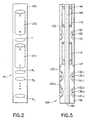
- a portion, 45, of the sonde 40 is a logging device 45, an embodiment of which is illustrated in Figure 2.
- a housing 240 contains permanent magnets 210 and 212, which have magnetization polarities as illustrated in the Figure, with opposing like polarities (designated N, in this case).
- a transmitting/receiving antenna, designated TR, is disposed between the magnets 210 and 212, and receiving antennas R1, R2 ... Rn are disposed, in longitudinally spaced apart relationship, on the other side of magnet 212.
- some or all receivers could be provided on the other side of magnet 210.
- at least two receivers are provided, and further receivers can be utilized to advantage, such as for implementing measurements that provide multiple depths of investigation.
- the housing 240 is at least partially formed of an insulating material, such as fiberglass.
- Part of the housing 240 can be metallic, but it should be insulating at least next to the transmitting and receiving antennas.
- a central tube such as a non-magnetic steel tube, supports the magnets 210 and 212, which can be tubular.
- the magnets can be, for example, rare earth magnets or ceramic magnets.
- the transmitting and receiving antennas of this embodiment are coils wound on insulating collars, which may be formed, for example, of a ceramic.
- the circuit wiring can be carried through the central tube.
- the fiberglass housing of the present embodiment can be oil filled and have a conventional pressure equalizing mechanism, such as a bellows.
- Circuitry coupled with the transmitting and receiving coils can be disposed within the housing 240 and/or, at least in part, disposed within the portion 42 of the sonde.
- An embodiment of the circuitry is shown in the diagram of Figure 3 for the case of two receivers, R1 and R2.
- a transmitter section includes an oscillator, represented at 310.
- An output of the oscillator 310 is coupled to a pulse former 315, the output of which is coupled to a power amplifier 318.
- the output of power amplifier 318 is coupled to a duplexer 320 which, in turn, is coupled to the input/output leads of the RF coil TR.
- the duplexer 320 is also coupled to an NMR receiving section that includes an amplifier 332, a phase sensitive detector 335, which also receives the oscillator output, and an analog-to-digital converter 340.
- the output of analog-to-digital converter 340 is coupled to a downhole processor 350, which may typically be a digital processor with associated memory and input/output circuitry (not separately shown).
- Timing control circuitry is associated with the processor, as represented at 352, and timing control is suitably provided as illustrated in the diagram.
- a Q-switch is provided, as represented at 345.
- Telemetry circuity 399 is conventionally provided for communicating with the
- the nuclear magnetic resonance circuitry can operate in three modes: transmitting, damping, and receiving.
- the transmitter section generates relatively large RF power of the order of 1 kilowatt at a frequency of the order of 1 MHz for a short precisely timed period, shuts off this current very quickly, within about 10 microseconds, and then isolates any signals or noise of the power circuits from coupling with detection circuitry.
- the system operates with a high Q, which can result in undesirable ringing.
- the Q-switch 345 is provided to reduce this problem.
- the Q switch closes a circuit at the appropriate time, which changes the impedance seen by conductors 111 so that the system is critically damped, and ringing energy is quickly dissipated.
- the duplexer 320 protects the receiver section from high power pulses during the transmitting and damping modes. During the receiving mode the duplexer couples the RF coil to the receiver amplifier 332. The amplified signal is coupled to phase sensitive detector 335, which also receives a reference signal from oscillator 310 that controls the frequency of sensitivity of the detector 335. The detected signal is converted to digital form by circuit 340, and coupled to processor 350. Ultimate transmission to the earth's surface for further known processing is implemented by circuitry 399. Reference can be made to the above referenced U.S. Patents No.s 4,933,638, 5,055,787, 5,055,788, and 5,376,884 for further details of circuitry and operation.
- the signal from receiver R1 is coupled via impedance matching circuit 360 and preamplifier 361 to one input of an electronically controlled switch 355.
- the signal from receiver R2 is coupled via impedance matching circuit 370 and preamplifier 371 to the other input of the switch 355.
- the switch 355, under control of processor 350, selects the near (R1) or the far (R2) receiver output.
- the selected signal is amplified by amplifier 356 and subsequently translated to a lower frequency f using a known heterodyne technique.
- a local oscillator is in a phase locked loop (represented at 381) with the master oscillator 310.
- the local oscillator 383 has a frequency f + ⁇ f, where ⁇ f is typically a few kilohertz or less.
- a signal from the local oscillator is mixed with the received signal by a mixer 358, and the mixer output is passed through a low pass filter 359 which blocks signals above ⁇ f and passes the signal at ⁇ f.
- the signal at frequency ⁇ f contains the phase and amplitude information of the original signal at frequency f.
- the recognized advantage of this frequency translation is that it is easier to measure the phase and amplitude at kilohertz or lower frequencies than at megahertz frequencies.
- the signal at frequency ⁇ f is measured with a phase meter 391 and with an amplitude meter 392, and the results are input to the processor 350.
- the phase meter 391 may utilize a reference signal from the phase locked loop 381.
- the phase and amplitude meters may also include sample-and-hold circuits, to implement comparison of the signals from the respective receivers.
- sample-and-hold circuits to implement comparison of the signals from the respective receivers.
- the processor may compute the relative phase and amplitude from the measurements it receives.
- U.S. Patent 4,899,112 which describes, inter alia, the obtaining of resistivity at different depths of investigation using the attenuation and phase derived signals.
- the processor 350 has associated memory, clocking, and interface circuitry, as is conventional.
- the processor implements storage of the measurements of phase and amplitude, processing of these measurements in the manner described in U.S. Patent 4,899,112, storage of the results of the processing, and/or coupling of the measurements to the telemetry subsystem for transmission to the earth's surface.
- a downhole clock can be utilized to keep track of time, which can subsequently be correlated with depth level by virtue of keeping a record of the drill string progress.
- the clock which can typically be part of the system in conjunction with the processor 350, can be synchronized with the system before a trip downhole.
- communication with the downhole system using mud pulse technology or other suitable communication means, can be utilized to convey timing synchronization and/or depth level information, as well as to communicate data in general. It will be understood that the embodiments of the invention can be utilized in conjunction with any suitable technique for keeping track of depth level.
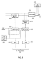
- a resistivity measurement can be made at the antenna TR, such as by determining the impedance looking into the antenna, which is affected by the formations, but is less preferred and will have a relatively shallow depth of investigation.
- a block diagram of a circuit for making this measurement is illustrated in Figure 6, which shows the antenna TR, duplexer 320, and Q-switch 345, as in Figure 3.
- the voltage and current coupled with the antenna are respectively measured by voltage meter 615 and current meter 610.
- the measured current and voltage are respectively coupled to two channel phase sensitive detectors 620 and 625 which each receive a reference signal from oscillator 310 and a 90 degree phase shifted version thereof, via the phase shifter 645.
- the respective outputs of the detectors are converted to digital form by analog to digital converters 630 and 635, and then coupled to processor 350 which determines resistivity as a function of the ratio of the signals.
- FIG. 4 there is illustrated an embodiment of the invention in the form of a logging-while-drilling apparatus and method.
- a platform and derrick 10 are positioned over a borehole 32 that is formed in the earth by rotary drilling.
- a drill string 12 is suspended within the borehole and includes a drill bit 415 at its lower end.
- the drill string 12, and the drill bit 415 attached thereto, is rotated by a rotating table 16 (energized by means not shown) which engages a kelly 17 at the upper end of the drill string.
- the drill string is suspended from a hook 18 attached to a travelling block (not shown).
- the kelly is connected to the hook through a rotary swivel 19 which permits rotation of the drill string relative to the hook.
- Drilling fluid or mud 26 is contained in a pit 27 in the earth.
- a pump 29 pumps the drilling fluid into the drill string 12 via a port in the swivel 19 to flow downward through the center of drill string 12.
- the drilling fluid exits the drill string via ports in the drill bit 415 and then circulates upward in the region between the outside of the drill string and the periphery of the borehole.
- the drilling fluid thereby carries formation cuttings to the surface of the earth, and the drilling fluid is returned to the pit 27 for recirculation.
- the small arrows in the Figure illustrate the typical direction of flow of the drilling fluid.
- Subsystem 100 mounted within the drill string 12, preferably near the drill bit 415, is a downhole sensing, processing, storing and transmitting subsystem 100.
- Subsystem 100 includes a measuring apparatus 200 in accordance with an embodiment of the invention, and which is illustrated in Figure 5.
- a communications transmitting portion of the downhole subsystem includes an acoustic transmitter 56, which generates an acoustic signal in the drilling fluid that is representative of the measured downhole conditions.
- acoustic transmitter which is known in the art, employs a device known as a "mud siren" which includes a slotted stator and a slotted rotor that rotates and repeatedly interrupts the flow of drilling fluid to establish a desired acoustic wave signal in the drilling fluid.
- the generated acoustic mud wave travels upward in the fluid through the center of the drill string at the speed of sound in the fluid.
- the acoustic wave is received at the surface of the earth by transducers represented by reference numeral 31.
- the transducers which are, for example, piezoelectric transducers, convert the received acoustic signals to electronic signals.
- the output of the transducers 31 is coupled to the uphole receiver subsystem 90 which is operative to demodulate the transmitted signals, which are then coupled to processor 85 and recorder 95.
- Transmitter 56 can be controlled by conventional transmitter control and driving electronics 57 which includes analog-to-digital (A/D) circuitry that converts the signals representative of downhole conditions into digital form.
- the control and driving electronics 57 may also include a suitable modulator, such as a phase shift keying (PSK) modulator, which conventionally produces driving signals for application to the transmitter 56.
- PSK phase shift keying
- These driving signals can be used to apply appropriate modulation to the mud siren of transmitter 56. It will be understood that alternative techniques can be employed for communicating logging information to the surface of the earth.
- the downhole subsystem 100 further includes acquisition and processor electronics 58, which can include electronics as shown in Figure 3.
- the acquisition and processor electronics 58 are coupled to the measuring apparatus 200 and obtain measurement information therefrom.
- the acquisition and processor electronics is capable of storing data from the measuring apparatus, processing the data and storing the results, and coupling any desired portion of the information it contains to the transmitter control and driving electronics 57 for transmission to the surface by transmitter 56.
- a battery 53 may provide downhole power.
- a downhole generator such as a so-called "mud turbine” powered by the drilling fluid, can also be utilized to provide power during drilling.
- the drilling equipment can optionally be a directional drilling equipment (not shown).
- Figure 5 illustrates an embodiment of the downhole measuring apparatus 200 (of Figure 4) in accordance with an embodiment of the apparatus.
- the general configuration is similar to that of Figure 2.
- the tool 200 is rotationally symmetric about axis 160 of the drill collar which is substantially aligned with the axis of the borehole.
- the static magnetic field is produced by tubular, axially polarized, permanent magnets 110 and 112 mounted inside the drill collar 140.
- Channel 145 located inside the tool and the magnets conveys drilling mud to the drill bit.
- the RF pulses necessary for the NMR measurement are produced by coil 120 located in a groove 123 in the outside of drill collar 140.
- NMR signal is detected by coil 120 in between the transmitted pulses.
- Coil 120 is mounted outside the drill collar because RF magnetic fields cannot penetrate the metallic drill collar.
- the impedance of coil 120 can be used to obtain an indication of the resistivity of the drilling mud and formation immediately around coil 120. While the RF pulses are being transmitted by coil 120, they are received by coils 130.1, 130.2,...,130.n. Only two receiver coils, 130.1 and 130.n are shown in Figure 2 for simplicity. Coils 130.1,...,130.n are located in grooves 133.1,..., 133.n in the outside of the drill collar 150. The coils 120, 130.1,...,130.n are protected from the abrasion and impact of the drilling environment by shields 121, 131.1,...,131.n, which can comprise slotted metallic tubes and/or insulating material.
- the coils 120, 130.1,...,130.n are separated from the drill collar 140, 150 by insulating spacers 122, 132.1,...,132.n which are preferably made of ferrite to increase the efficiency of the coils.
- Drill collars 140 and 150 can be screwed into each other by the threaded joint 147. This simplifies mounting and servicing of magnet 112.
Landscapes
- Physics & Mathematics (AREA)
- Life Sciences & Earth Sciences (AREA)
- High Energy & Nuclear Physics (AREA)
- Engineering & Computer Science (AREA)
- Environmental & Geological Engineering (AREA)
- Geology (AREA)
- Remote Sensing (AREA)
- General Life Sciences & Earth Sciences (AREA)
- General Physics & Mathematics (AREA)
- Geophysics (AREA)
- Geophysics And Detection Of Objects (AREA)
Description
A logging device is moveable through the borehole and includes: means for producing a static magnetic field; a transmitting antenna; means for energizing the transmitting antenna with an oscillating signal to produce electromagnetic energy; a first receiver circuit coupled with the transmitting antenna for receiving nuclear magnetic resonance signals from the formations; and means for deriving, from the received nuclear magnetic resonance signals, a nuclear magnetic resonance property of the formations. Also provided are at least one receiving antenna spaced from the transmitting antenna; a second receiver circuit coupled with the at least one receiving antenna for receiving electromagnetic energy that has been emitted by the transmitting antenna and propagated through the formations; and means coupled with the second receiver circuit for deriving, from the received electromagnetic energy, the resistivity of the formations.
Claims (15)
- Apparatus for determining both a nuclear magnetic resonance characteristic and resistivity of earth formations (31) surrounding a borehole (32), comprising:and characterized by:a logging device (200) moveable through the borehole (32), and including:means for producing a static magnetic field (110,112);a transmitting antenna (TR/120);means for energizing said transmitting antenna with an oscillating signal to produce electromagnetic energy (310, 315, 318);a first receiver circuit coupled with said transmitting antenna for receiving nuclear magnetic resonance signals from said formations (332, 335, 340);means for deriving, from said received nuclear magnetic resonance signals, a nuclear magnetic resonance property of said formations (350);at least one receiving antenna (R1/130.1, R2/130.n) spaced from said transmitting antenna (TR/120);a second receiver circuit coupled with said at least one receiving antenna (R1/130.1, R2/130.n) for receiving electromagnetic energy that has been emitted by the transmitting antenna (TR/120) and propagated through said formations (360, 361, 370, 371, 355, 356); andmeans coupled with said second receiver circuit for deriving, from the received electromagnetic energy, the resistivity of said formations (359, 391, 392, 350).
- Apparatus as defined by claim 1, wherein said at least one receiving antenna (R1/130.1, R2/130.n) comprises a spaced apart pair of receiving antennas (R1/130.1, R2/130.n).
- Apparatus as defined by claim 2, wherein said transmitting antenna (TR/120) and said receiving antennas (R1/130.1, R2/130.n) comprise coils.
- Apparatus as defined by either claim 2 or claim 3, wherein said means for producing said static magnetic field (110, 112) comprises at least one permanent magnet (110, 112).
- Apparatus as defined by either claim 2 or claim 3, wherein said means for producing said static magnetic field comprises first (110) and second (112) longitudinally aligned and longitudinally spaced elongated permanent magnets, and wherein said transmitting antenna (TR/120) is disposed between said permanent magnets (110, 112) and said receiving antennas (R1/130.1, R2/130.n) are disposed past one longitudinal end of one of said permanent magnets (110, 112).
- Apparatus as defined by any one of claims 2 to 5, wherein said means for deriving the resistivity of said formations (359, 391, 392, 350) includes means for determining the relative phase of the electromagnetic energy received at said pair of receiving antennas (391, 350).
- Apparatus as defined by any one of claims 2 to 6, wherein said means for deriving the resistivity of said formations (359, 391, 392, 350) includes means for determining the relative amplitude of the electromagnetic energy received at said pair of receiving antennas (392, 350).
- Apparatus as defined by any one of claims 1 to 7, wherein said oscillating signal is an RF signal.
- Apparatus as defined by any one of claims 1 to 8, wherein said logging device (200) is mounted in a drill string (12) in said borehole (32).
- A method for determining a nuclear magnetic resonance characteristic and the resistivity of earth formations (31) surrounding a borehole (32), comprising the steps of:and characterized by:passing a logging device (200) through the borehole (32);producing, at said logging device (200), a static magnetic field;producing, at a transmitter location (122) of said logging device (200), electromagnetic energy having a field component in said formations (31) that is orthogonal to said static magnetic field;receiving, at said transmitter location (122), nuclear magnetic resonance signals from said formations (31);determining, from said received nuclear magnetic resonance signals, a nuclear magnetic resonance characteristic of said formations (31);receiving, at at least one receiver location (132.1, 132.n) of said logging device (200) that is spaced from said transmitter location (122), electromagnetic energy that has been emitted at said transmitter location (122) and passed through said formations (31); anddetermining, from said electromagnetic energy received at said at least one receiver location (132.1, 132.n), the resistivity of said formations (31).
- The method as defined by claim 10, wherein said at least one receiver location (132.1, 132.n) comprises first (132.1) and second (132.n) spaced apart receiver locations.
- The method as defined by claim 11, wherein said step of determining the resistivity of said formations (31) from electromagnetic energy received at said first (132.1) and second (132.n) receiver locations includes determining the relative phase of the electromagnetic energy received at said first (132.1) and second (132.n) receiver locations.
- The method as defined by either claim 11 or 12, wherein said step of determining the resistivity of said formations (31) from electromagnetic energy received at said first (132.1) and second (132.n) receiver locations includes determining the relative amplitude of the electromagnetic energy received at said first (132.1) and second (132.n) receiver locations.
- The method as defined by any one of claims 10 to 13, wherein said electromagnetic energy is RF electromagnetic energy.
- The method as defined by any one of claims 10 to 14, wherein said step of passing a logging device (200) through said borehole (32) comprises attaching said logging device (200) to a drill string (12) that is moved through said borehole (32).
Applications Claiming Priority (3)
| Application Number | Priority Date | Filing Date | Title |
|---|---|---|---|
| US08/759,829 US5831433A (en) | 1996-12-04 | 1996-12-04 | Well logging method and apparatus for NMR and resistivity measurements |
| US759829 | 1996-12-04 | ||
| PCT/US1997/021889 WO1998025164A2 (en) | 1996-12-04 | 1997-11-26 | Well logging method and apparatus for nmr and resistivity measurements |
Publications (2)
| Publication Number | Publication Date |
|---|---|
| EP0885400A2 EP0885400A2 (en) | 1998-12-23 |
| EP0885400B1 true EP0885400B1 (en) | 2003-08-20 |
Family
ID=25057116
Family Applications (1)
| Application Number | Title | Priority Date | Filing Date |
|---|---|---|---|
| EP97953064A Expired - Lifetime EP0885400B1 (en) | 1996-12-04 | 1997-11-26 | Well logging method and apparatus for nmr and resistivity measurements |
Country Status (6)
| Country | Link |
|---|---|
| US (1) | US5831433A (en) |
| EP (1) | EP0885400B1 (en) |
| CA (1) | CA2245720C (en) |
| DE (1) | DE69724238D1 (en) |
| NO (1) | NO983350L (en) |
| WO (1) | WO1998025164A2 (en) |
Families Citing this family (28)
| Publication number | Priority date | Publication date | Assignee | Title |
|---|---|---|---|---|
| US5814988A (en) * | 1997-01-29 | 1998-09-29 | Western Atlas International, Inc. | Combination nuclear magnetic resonance and electromagnetic induction resistivity well logging instrument and method |
| GB2325981B (en) * | 1997-04-21 | 2002-04-10 | Baker Hughes Inc | Nuclear magnetic resonance apparatus and method for geological applications |
| US6255817B1 (en) * | 1997-06-23 | 2001-07-03 | Schlumberger Technology Corporation | Nuclear magnetic resonance logging with azimuthal resolution |
| US6377042B1 (en) | 1998-08-31 | 2002-04-23 | Numar Corporation | Method and apparatus for merging of NMR echo trains in the time domain |
| US6977499B2 (en) * | 1999-02-09 | 2005-12-20 | Baker Hughes Incorporated | Formation-based interpretation of NMR data for carbonate reservoirs |
| US6661226B1 (en) | 1999-08-13 | 2003-12-09 | Halliburton Energy Services, Inc. | NMR apparatus and methods for measuring volumes of hydrocarbon gas and oil |
| US6541969B2 (en) | 1999-12-15 | 2003-04-01 | Halliburton Energy Services, Inc. | Method and apparatus for improving the vertical resolution of NMR logs |
| US6445187B1 (en) | 2000-04-10 | 2002-09-03 | Jerry R. Montgomery | System for the measurement of electrical characteristics of geological formations from within steel cased wells using magnetic circuits |
| US6445180B1 (en) | 2000-06-28 | 2002-09-03 | Baker Hughes Incorporated | Nuclear magnetic resonance tool with active RF spoiler antenna |
| FR2811767B1 (en) * | 2000-07-13 | 2002-09-20 | Innov Pro | DEVICE FOR EVALUATING THE DENSITY OF PROTONS PRESENT IN A GIVEN BODY |
| US6439046B1 (en) | 2000-08-15 | 2002-08-27 | Baker Hughes Incorporated | Apparatus and method for synchronized formation measurement |
| CA2325348C (en) | 2000-11-08 | 2011-01-11 | University Technologies International Inc. | Quantification of bitumen using nmr |
| US7135862B2 (en) | 2001-03-13 | 2006-11-14 | Halliburton Energy Services, Inc | NMR logging using time-domain averaging |
| US6603309B2 (en) * | 2001-05-21 | 2003-08-05 | Baker Hughes Incorporated | Active signal conditioning circuitry for well logging and monitoring while drilling nuclear magnetic resonance spectrometers |
| US6518756B1 (en) | 2001-06-14 | 2003-02-11 | Halliburton Energy Services, Inc. | Systems and methods for determining motion tool parameters in borehole logging |
| US6525534B2 (en) | 2001-06-15 | 2003-02-25 | Halliburton Energy Services, Inc. | System and methods for NMR signal processing without phase alternated pair stacking |
| US6938469B2 (en) * | 2003-08-06 | 2005-09-06 | Schlumberger Technology Corporation | Method for determining properties of formation fluids |
| US8117018B2 (en) * | 2008-01-25 | 2012-02-14 | Baker Hughes Incorporated | Determining structural dip and azimuth from LWD resistivity measurements in anisotropic formations |
| US8836328B2 (en) * | 2010-02-03 | 2014-09-16 | Baker Hughes Incorporated | Acoustic excitation with NMR pulse |
| US8967248B2 (en) * | 2011-08-23 | 2015-03-03 | Harris Corporation | Method for hydrocarbon resource recovery including actuator operated positioning of an RF sensor and related apparatus |
| US20150114625A1 (en) * | 2013-10-29 | 2015-04-30 | Schlumberger Technology Corporation | Method of Acquiring Viscosity of A Downhole Fluid |
| KR101673240B1 (en) * | 2014-11-13 | 2016-11-07 | 주식회사 에이치시티엠 | Permanent magnet structure for mobile terminal |
| US20160170066A1 (en) * | 2014-12-11 | 2016-06-16 | Schlumberger Technology Corporation | Probability Distribution Based Logging Tool Data Compression |
| US20160170067A1 (en) * | 2014-12-11 | 2016-06-16 | Schlumberger Technology Corporation | Logging Tool Providing Measured Response Database Comparison |
| GB2545861B (en) * | 2014-12-30 | 2021-04-07 | Halliburton Energy Services Inc | Combined NMR-resistivity measurement apparatus, systems, and methods |
| BR112017015590A2 (en) * | 2015-03-31 | 2018-03-13 | Halliburton Energy Services Inc | nuclear magnetic resonance sensor device, and, well inspection system, and, method for making nuclear magnetic resonance measurements |
| WO2017058239A1 (en) | 2015-10-02 | 2017-04-06 | Halliburton Energy Services, Inc. | Logging-while-drilling tool with interleaved instruments |
| US11143782B2 (en) * | 2018-06-22 | 2021-10-12 | Baker Hughes, A Ge Company, Llc | Downhole NMR tool with receiver on sensor |
Family Cites Families (14)
| Publication number | Priority date | Publication date | Assignee | Title |
|---|---|---|---|---|
| US3597681A (en) * | 1957-01-30 | 1971-08-03 | Chevron Res | Nuclear magnetic well logging |
| US4185238A (en) * | 1977-09-21 | 1980-01-22 | Schlumberger Technology Corporation | Apparatus and method for determination of subsurface permittivity and conductivity |
| US4350955A (en) * | 1980-10-10 | 1982-09-21 | The United States Of America As Represented By The United States Department Of Energy | Magnetic resonance apparatus |
| US5055788A (en) * | 1986-08-27 | 1991-10-08 | Schlumberger Technology Corporation | Borehole measurement of NMR characteristics of earth formations |
| US4933638A (en) * | 1986-08-27 | 1990-06-12 | Schlumber Technology Corp. | Borehole measurement of NMR characteristics of earth formations, and interpretations thereof |
| US5157605A (en) * | 1987-04-27 | 1992-10-20 | Schlumberger Technology Corporation | Induction logging method and apparatus including means for combining on-phase and quadrature components of signals received at varying frequencies and including use of multiple receiver means associated with a single transmitter |
| US4899112A (en) * | 1987-10-30 | 1990-02-06 | Schlumberger Technology Corporation | Well logging apparatus and method for determining formation resistivity at a shallow and a deep depth |
| GB9021257D0 (en) * | 1990-09-29 | 1990-11-14 | Guilfoyle David N | Method and apparatus for measuring the flow of a fluid through porous media by echo planar imaging |
| WO1992010768A1 (en) * | 1990-12-05 | 1992-06-25 | Numar Corporation | System for logging a well during the drilling thereof |
| US5557200A (en) * | 1991-05-16 | 1996-09-17 | Numar Corporation | Nuclear magnetic resonance determination of petrophysical properties of geologic structures |
| EP0581666B1 (en) * | 1992-07-30 | 1997-10-01 | Schlumberger Limited | Pulsed nuclear magnetism tool for formation evaluation while drilling |
| US5376884A (en) * | 1993-04-01 | 1994-12-27 | Schlumberger Technology Corporation | Nuclear magnetic resonance measuring apparatus |
| GB9308806D0 (en) * | 1993-04-28 | 1993-06-09 | Bpb Industries Plc | Induction sonde |
| US5828214A (en) * | 1996-02-23 | 1998-10-27 | Western Atlas International, Inc. | Method and apparatus for resistivity determination by nuclear magnetic resonance measurement |
-
1996
- 1996-12-04 US US08/759,829 patent/US5831433A/en not_active Expired - Lifetime
-
1997
- 1997-11-26 EP EP97953064A patent/EP0885400B1/en not_active Expired - Lifetime
- 1997-11-26 WO PCT/US1997/021889 patent/WO1998025164A2/en active IP Right Grant
- 1997-11-26 DE DE69724238T patent/DE69724238D1/en not_active Expired - Lifetime
- 1997-11-26 CA CA002245720A patent/CA2245720C/en not_active Expired - Fee Related
-
1998
- 1998-07-20 NO NO983350A patent/NO983350L/en unknown
Also Published As
| Publication number | Publication date |
|---|---|
| CA2245720A1 (en) | 1998-06-11 |
| WO1998025164A3 (en) | 1998-07-16 |
| EP0885400A2 (en) | 1998-12-23 |
| WO1998025164A2 (en) | 1998-06-11 |
| DE69724238D1 (en) | 2003-09-25 |
| CA2245720C (en) | 2004-09-07 |
| NO983350D0 (en) | 1998-07-20 |
| NO983350L (en) | 1998-10-05 |
| US5831433A (en) | 1998-11-03 |
Similar Documents
| Publication | Publication Date | Title |
|---|---|---|
| EP0885400B1 (en) | Well logging method and apparatus for nmr and resistivity measurements | |
| US5376884A (en) | Nuclear magnetic resonance measuring apparatus | |
| CA2241591C (en) | Nuclear magnetic resonance logging with azimuthal resolution | |
| US6366089B1 (en) | Nuclear magnetic resonance logging with azimuthal resolution | |
| US4553097A (en) | Well logging apparatus and method using transverse magnetic mode | |
| US5594343A (en) | Well logging apparatus and method with borehole compensation including multiple transmitting antennas asymmetrically disposed about a pair of receiving antennas | |
| US6018243A (en) | NMR well logging apparatus and method | |
| US5828214A (en) | Method and apparatus for resistivity determination by nuclear magnetic resonance measurement | |
| US5629623A (en) | Pulsed nuclear magnetism tool for formation evaluation while drilling | |
| US4968940A (en) | Well logging apparatus and method using two spaced apart transmitters with two receivers located between the transmitters | |
| US4899112A (en) | Well logging apparatus and method for determining formation resistivity at a shallow and a deep depth | |
| US4949045A (en) | Well logging apparatus having a cylindrical housing with antennas formed in recesses and covered with a waterproof rubber layer | |
| CA2197931C (en) | Nuclear magnetic resonance well logging apparatus and method adapted for measurement-while-drilling | |
| US5672971A (en) | Well logging system arranged for stable, high-sensitivity reception of propagating electromagnetic waves | |
| US6957708B2 (en) | Electrical imaging in conductive and non-conductive mud | |
| US6121773A (en) | Longitudinal NMR well logging apparatus and method | |
| US5900733A (en) | Well logging method and apparatus for determining downhole Borehole fluid resistivity, borehole diameter, and borehole corrected formation resistivity | |
| US5959453A (en) | Radial NMR well logging apparatus and method | |
| GB2348506A (en) | NMR well logging tool with low profile antenna | |
| CA2232654C (en) | Nmr well logging apparatus and method | |
| US6417667B1 (en) | Method for logging and determining wellbore diameter by processing of progressive subsurface electromagnetic resistivity measurements | |
| CA2270757C (en) | Nuclear magnetic resonance logging with azimuthal resolution | |
| GB2324376A (en) | Nuclear magnetic resonance well logging |
Legal Events
| Date | Code | Title | Description |
|---|---|---|---|
| PUAI | Public reference made under article 153(3) epc to a published international application that has entered the european phase |
Free format text: ORIGINAL CODE: 0009012 |
|
| 17P | Request for examination filed |
Effective date: 19980723 |
|
| AK | Designated contracting states |
Kind code of ref document: A2 Designated state(s): DE DK FR GB IT NL |
|
| 17Q | First examination report despatched |
Effective date: 20011029 |
|
| GRAH | Despatch of communication of intention to grant a patent |
Free format text: ORIGINAL CODE: EPIDOS IGRA |
|
| GRAS | Grant fee paid |
Free format text: ORIGINAL CODE: EPIDOSNIGR3 |
|
| GRAA | (expected) grant |
Free format text: ORIGINAL CODE: 0009210 |
|
| AK | Designated contracting states |
Designated state(s): DE DK FR GB IT NL |
|
| PG25 | Lapsed in a contracting state [announced via postgrant information from national office to epo] |
Ref country code: NL Free format text: LAPSE BECAUSE OF FAILURE TO SUBMIT A TRANSLATION OF THE DESCRIPTION OR TO PAY THE FEE WITHIN THE PRESCRIBED TIME-LIMIT Effective date: 20030820 Ref country code: IT Free format text: LAPSE BECAUSE OF FAILURE TO SUBMIT A TRANSLATION OF THE DESCRIPTION OR TO PAY THE FEE WITHIN THE PRESCRIBED TIME-LIMIT;WARNING: LAPSES OF ITALIAN PATENTS WITH EFFECTIVE DATE BEFORE 2007 MAY HAVE OCCURRED AT ANY TIME BEFORE 2007. THE CORRECT EFFECTIVE DATE MAY BE DIFFERENT FROM THE ONE RECORDED. Effective date: 20030820 Ref country code: FR Free format text: LAPSE BECAUSE OF FAILURE TO SUBMIT A TRANSLATION OF THE DESCRIPTION OR TO PAY THE FEE WITHIN THE PRESCRIBED TIME-LIMIT Effective date: 20030820 |
|
| REG | Reference to a national code |
Ref country code: GB Ref legal event code: FG4D |
|
| REF | Corresponds to: |
Ref document number: 69724238 Country of ref document: DE Date of ref document: 20030925 Kind code of ref document: P |
|
| PG25 | Lapsed in a contracting state [announced via postgrant information from national office to epo] |
Ref country code: DK Free format text: LAPSE BECAUSE OF FAILURE TO SUBMIT A TRANSLATION OF THE DESCRIPTION OR TO PAY THE FEE WITHIN THE PRESCRIBED TIME-LIMIT Effective date: 20031120 |
|
| PG25 | Lapsed in a contracting state [announced via postgrant information from national office to epo] |
Ref country code: DE Free format text: LAPSE BECAUSE OF FAILURE TO SUBMIT A TRANSLATION OF THE DESCRIPTION OR TO PAY THE FEE WITHIN THE PRESCRIBED TIME-LIMIT Effective date: 20031121 |
|
| NLV1 | Nl: lapsed or annulled due to failure to fulfill the requirements of art. 29p and 29m of the patents act | ||
| PLBE | No opposition filed within time limit |
Free format text: ORIGINAL CODE: 0009261 |
|
| STAA | Information on the status of an ep patent application or granted ep patent |
Free format text: STATUS: NO OPPOSITION FILED WITHIN TIME LIMIT |
|
| 26N | No opposition filed |
Effective date: 20040524 |
|
| EN | Fr: translation not filed | ||
| PGFP | Annual fee paid to national office [announced via postgrant information from national office to epo] |
Ref country code: GB Payment date: 20121121 Year of fee payment: 16 |
|
| GBPC | Gb: european patent ceased through non-payment of renewal fee |
Effective date: 20131126 |
|
| PG25 | Lapsed in a contracting state [announced via postgrant information from national office to epo] |
Ref country code: GB Free format text: LAPSE BECAUSE OF NON-PAYMENT OF DUE FEES Effective date: 20131126 |