BACKGROUND OF THE INVENTION
This application claims priority under 35 U.S.C. § § 119 and/or 365
to Hei 9-155033 filed in Japan on June 12, 1997, the entire contents of
which is herein incorporated by reference.
Field of the Invention
The present invention relates to a mobile communication system
that involves periodic switching of the transmitted frequencies by a
frequency hopping technique.
Description of the Prior Art
A conventional mobile communication system will be described
first with reference to Fig. 12 which depicts it in conceptual form.
Reference numeral 10 denotes a mobile station, and 11 a base
station. Data is transmitted and received between the base station 11 and
the mobile station 10. Reference numeral 12 denotes a radio cell, which
indicates the coverage area surrounding the base station 11 and
within which data is exchanged between the base and mobile stations
11 and 10.
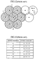
A septuplet of radio cells 12 constitute one area as indicated by
hatching in Fig. 12. The frequencies that are assigned to each of such
areas repeat in a cyclic order; that is, the areas are common in the
frequencies assigned thereto. Each area made up of seven radio cells
will hereinafter be referred to as a repetition area. Further the number of
radio cells forming the repetition area will hereinafter be referred to
as a repetition cell number. In the prior art example of Fig. 12 the
repetition cell number is seven.
Furthermore, the radio cells forming the repetition area are each
assigned a plurality of frequencies, which will hereinafter be referred
to as a frequency group. And the radio cells making up the repetition
area are each assigned seven different frequency groups.
The base station 11 has control over the mobile stations 10
belonging to its radio cell and allocates to each mobile station 10 a
hopping sequence for frequency hopping use.
Next, a description will be given of the operation of the
conventional mobile communication system conceptually depicted in
Fig. 12.
In Fig. 12 the base station 11 specifies predetermined hopping
sequences for all the mobile stations 10 placed under its control.
Based on the hopping sequence specified by the base station 11, each
mobile station 10 performs frequency hopping.
Now, a description will be given, with reference to Fig. 13, of
hopping sequences c1, c2, c3, c4, c5 and c6 that are specified for a cell
A or B when it is assigned frequencies f1, f2 and f3. Let it be
assumed that mobile stations M1 to m3 are present in the cell A and
mobile stations M4 to m6 in the cell B.
Suppose that the mobile station M1 is assigned the hopping
sequence c1, the mobile station m2 the hopping sequence c2, the
mobile station m3 the hopping sequence m3, the mobile station M4
the hopping sequence c4, the mobile station m5 the hopping sequence
c5 and the mobile station m6 the hopping sequence c6. The mobile
stations M1 to m6 perform frequency hopping with fixed hopping
periods based on the hopping sequences c1 to c6 respectively
assigned to them. The frequencies f1, f2 and f3 will hereinafter called
first, second and third frequencies in this order.
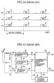
Turning next to Fig. 14, a description will be made of how
frequency hopping takes place, for example, in the mobile stations M1
to m3 in the cell A. The abscissa represents time.
The mobile station M1 uses the frequencies f1, f2 and f3 when it
outputs bursts B1, B2 and B3, respectively. The mobile station m2
uses the frequencies f2, f3 and f1 when it outputs bursts B1, B2 and
B3, respectively. The mobile station m3 uses the frequencies f3, f1
and f2 when it outputs bursts B1, B2 and B3, respectively.
The bursts B1 to B3 mentioned herein are pulse-like waves or
waveforms created by dividing original data such as speech and adding
a header or the like to each divided piece of data. By virtue of the
hopping sequences c1 to c3 assigned thereto, respectively, the mobile
stations M1 to m3 in the cell A will not he assigned the same
frequency at the same timing. Likewise, the mobile stations M4 to m6
in the cell B will not be assigned the same frequency at the same
timing.
Fig. 15 depicts in block form the mobile station 10 that forms the
conventional mobile communication system. With reference to Fig.
15, the configuration of the conventional mobile station 10 will be
described.
In Fig. 15, reference numeral 20 denotes an antenna. Reference
numeral 21 denotes a transmitting part, which is connected via a
switch 22 to the antenna 20. Reference numeral 23 denotes a
receiving part, which is also connected via the switch 22 to the
antenna 20. Reference numeral 24 denotes a transmission/received data
processing part, which is connected to the transmitting part 21 and
the receiving part 23. Reference numeral 25 denotes a synthesizer
part, which is connected to the transmitting part 21, the receiving
part 23 and the transmission/received data processing part 24. Reference
numeral 26 denotes a control part, which is connected to the
transmission/received data processing part 24 and the synthesizer part 25.
Reference numeral 24i denotes transmission data, which is input into
the transmission/received data processing part 24. Reference numeral 24t
denotes transmission burst data, which is provided from the
transmission/received data processing part 24 to the transmitting part 21. Reference
numeral 21t denotes a transmission signal, which is output from the
transmitting part 21. Reference numeral 23r denotes a received
signal, which is input into the receiving part 23. Reference numeral
24r denotes received burst data, which is provided from the receiving
part 23 to the transmission/received data processing part 24.
Reference numeral 24o denotes received data, which is output
from the transmission/received data processing part 24. Reference numeral
25t denotes transmission frequency data, which is provided from the
synthesizer part 25 to the transmitting part 21. Reference numeral
25r denotes receive frequency data, which is provided from the
synthesizer part 25 to the receiving part 23. Reference numeral 26r
denotes hopping sequence data, which is provided from the transmission/received
data processing part 24 to the control part 26. The transmission/received data
processing part 24 instructs the control part 26 to perform frequency hopping
based on the hopping sequence data 26r.
Reference numeral 26t denotes first switching data, which is
provided from the control part 26 and fed into the synthesizer part
25. The synthesizer part 25 operates on the first switching data 26t,
performing frequency hopping. Reference numeral 24g denotes a
timing signal, which is provided from the transmission/received data
processing part 24 and fed into the synthesizer part 25. The timing
signal 24g is output from the transmission/received data processing part 24
based on the received burst data 24r.
Next, the operation of the conventional mobile station 10 will be
described below.
The mobile station 10 receives signals sent from the base station
11 by the antenna 20. The received signal 23r is applied from the
antenna 20 to the receiving part 23 via the switch 22. When supplied
with the received signal 23r, the receiving part 23 demodulates it and
outputs the received burst data 24r, which is fed into the transmission/received
data processing part 24.
The transmission/received data processing part 24 decodes the received
burst data and outputs the received data 24o. Further, the
transmission/received data processing part 24 extracts the hopping sequence data
26r from the received burst data 24r. The transmission/received data
processing part 24 applies the timing signal 24g to the synthesizer 25.
Additionally, the transmission/received data processing part 24 is supplied
with the transmission data 24i and generates therefrom the transmission burst
data 24t, which is fed into the transmitting part 21. The hopping sequence
data 26r output from the transmission/received data processing part 24 is
input into the control part 26.
Based on the hopping sequence data 26r input thereinto, the
control part 26 determines the frequency desired to hop. And the
control part 26 uses the first switching data 26t to indicate the thus
determined hopping frequency to the synthesizer part 25. The
synthesizer part 25 further receives the timing signal 24g from the
transmission/received data processing part 24, and determines the frequency
to hop and its timing.
Based on the first switching data 26t fed thereinto, the
synthesizer part 25 provides the transmission frequency data 25t or received
frequency data 25r to the transmitting part 21 or receiving part 23 so
that the frequency to be used by the mobile communication system
equipped with the synthesizer part 25 is switched, for example, from
a first to a second frequency.
When the synthesizer part 25 indicates a predetermined
frequency to the transmitting part 21, the former provides the transmission
frequency data 25t to the latter. When the synthesizer part 25
indicates a predetermined frequency to the receiving part 23, the
former provides the received frequency data 25t to the latter. The transmission
burst data 24t provided from the transmission/received data processing
part 24 is input into the transmitting part 21. Supplied with the transmission
burst data 24t, the transmitting part 21 modulates it based on the
transmission frequency data 25t and outputs the transmission signal 21t. The
transmission signal 21t provided from the transmitting part 21 is sent to the
base station 11 via the switch 22 and the antenna 20.
With the conventional mobile communication system described
above, frequency hopping is performed in a predetermined cycle
regardless of the receiving conditions of the mobile station. Hence, a
poor receiving level may sometimes be switched to a high receiving
level, but the cyclic or periodic frequency hopping gives rise to a
problem that a high receiving level may be switched to a low level.
Another problem of the prior art is that no particular attention is paid
to interferences.
SUMMARY OF THE INVENTION
It is therefore a primary object of the present invention to
provide a mobile communication system which, when the mobile
station and the base station communicate with each other, performs
frequency hopping based on the receiving level of the mobile or base
station, thereby permitting enhancement of speech quality.
A secondary object of the present invention is to provide a
mobile communication system which performs frequency hopping
only at frequencies of high receiving level, ensuring excellent speech
quality.
To attain the above objective, according to a first aspect of the
present invention, there is provided a mobile communication system
which comprises a base station and a mobile station that
communicates therewith while performing frequency hopping based
on a predetermined hopping sequence and in which, based on the
received power of a signal received from the base station at a first
frequency in the hopping sequence, the mobile station switches the
first frequency to a second one next thereto in the hopping sequence
and keeps on communicating with the base station at the second
frequency. This system configuration permits high-quality, high-reliability
communications between the base and the mobile station.
According to a second aspect of the present invention, there is
provided a mobile communication system in which, when the received
power of a signal received by a mobile station from a base station at a
first frequency in a hopping sequence is above a predetermined
power level, the mobile station communicates with the base station at
the first frequency, whereas when the received power is below the
predetermined power level the mobile station switches the first
frequency to a second one next thereto in the hopping sequence and
continues to communicate with the base station at the second
frequency. Thus, when the power level of the mobile station is low,
frequency hopping is carried out so that the frequency for use in the
mobile station is switched to facilitate communications with the base
station at a higher power level. When the received power level of the
mobile station is already high, no frequency hopping takes place, and
hence the frequency being used in the mobile station remains
unswitched so as to continue communications with the base station at
the high power level. This also provides high-quality, high-reliability
communications between the base and the mobile station.
According to a third aspect of the present invention, there is
provided a mobile communication system which comprises a base
station and a mobile station that communicates therewith while
performing frequency hopping based on a predetermined hopping
sequence and in which the mobile station outputs information based
on the received power of a signal received from the base station at a
first frequency in the hopping sequence and, based on the information
received from the mobile station, the base station switches the first
frequency to a second one next thereto in the hopping sequence and
keeps on communicating with the mobile station at the second
frequency. This system configuration also permits high-quality, high-reliability
communications between the base and the mobile station.
According to a fourth aspect of the present invention, there is
provided a mobile communication system which comprises a mobile
station and a base station that communicates therewith while
performing frequency hopping based on a predetermined hopping
sequence and in which, based on the received power of a signal
received from the mobile station at a first frequency in the hopping
sequence, the base station switches the first frequency to a second
one next thereto in the hopping sequence and keeps on
communicating with the mobile station at the second frequency. This
system configuration also permits high-quality, high-reliability
communications between the base and the mobile station.
According to a fifth aspect of the present invention, there is
provided a mobile communication system which, when the received
power of a signal received by a base station from a mobile station at a
first frequency in a hopping sequence is above a predetermined
power level, the base station communicates with the mobile station at
the first frequency, whereas when the received power is below the
predetermined power level the base station switches the first
frequency to a second one next thereto in the hopping sequence and
continues to communicate with the mobile station at the second
frequency. Thus, when the received power level of the mobile station
is low, frequency hopping is carried out so that the frequency for use
in the mobile station is switched to facilitate communications at a
higher power level. When the received power level of the mobile
station is already high, no frequency hopping takes place, and hence
the frequency being used in the mobile station remains unswitched so
as to continue communications with the base station at the high power
level. This system configuration also provides high-quality, high-reliability
communications between the base and the mobile station.
According to a sixth aspect of the present invention, there is
provided a mobile communication system which comprises a mobile
station and a base station that communicates therewith while
performing frequency hopping based on a predetermined hopping
sequence and in which the base station outputs information based on
the received power of a signal received from the mobile station at a
first frequency in the hopping sequence and, based on the information
received from the base station, the mobile station switches the first
frequency to a second one next thereto in the hopping sequence and
continues to communicate with the base station at the second
frequency. This system configuration also permits high-quality, high-reliability
communications between the base and the mobile station.
According to a seventh aspect of the present invention, there is
provided a mobile communication system which, based on the
received power of an interference received together with a
received signal from the mobile station at a first frequency, switches
the first frequency to a second one next thereto in the hopping
sequence and thereafter establishes communications between a base
and a mobile station at the second frequency. This system
configuration also provides high-quality, high-reliability
communications between the base and mobile station.
According to an eighth aspect of the present invention, there is
provided a mobile communication system in which, when the received
power of an interference received together with a received signal of a
first frequency in a hopping sequence is below a predetermined
power level, a base and a mobile station communicate with each other
at the first frequency, whereas when the received power of the
interference is above the predetermined power level the first
frequency is switched to a second frequency next thereto in the
hopping sequence for subsequent communications between the base
and the mobile station. Thus, when the mobile station is low in the
received power level for the desired received signal but high for the
interference, frequency hopping is carried out so that the
frequency for use in the mobile station is switched to raise the
received power level of the desired received signal and reduce that of
the interference. When the received power level of the desired signal
is already high and that of the interference is low, no frequency
hopping takes place, and hence the frequency being used in the
mobile station remains unswitched so as to hold the power level high
for the desired received signal and the power level low for the
interference. This system configuration also provides high-quality,
high-reliability communications between the base and the
mobile station.
According to a ninth aspect of the present invention, there is
provided a mobile communication system which comprises a base
station and a mobile station that communicates therewith while
performing frequency hopping based on a predetermined hopping
sequence and in which, based on the received power of an
interference received together with a received signal from the
base station at a first frequency in the hopping sequence, the mobile
station switches the first frequency to a second one next thereto in
the hopping sequence and thereafter establishes communications with
the base station at the second frequency. This system configuration
also permits high-quality, high-reliability communications between
the base and the mobile station.
According to a tenth aspect of the present invention, there is
provided a mobile communication system in which, when the received
power of an interference received together with a received signal
from a base station at a first frequency in a hopping
sequence is below a predetermined power level, a mobile station
communicates with the base station at the first frequency, whereas
when the received power of the interference wave above the
predetermined power level the mobile station switches the first
frequency to a second one next thereto in the hopping sequence and
thereafter establishes communications with the base station at the
second frequency. Thus, when the mobile station receives the
interference at a high power level, frequency hopping is carried
out so that the frequency for use in the mobile station is switched to
reduce the received power level of the interference. When the
received power level of the mobile station is already low, no
frequency hopping takes place, and hence the frequency being used in
the mobile station remains unswitched so as to continue
communications with the base station while retaining the received
power level low for the interference. This system configuration
also provides high-quality, high-reliability communications between
the base and the mobile station.
According to an eleventh aspect of the present invention, there is
provided a mobile communication system which comprises a base
station and a mobile station that communicates therewith while
performing frequency hopping based on a predetermined hopping
sequence and in which the mobile station outputs information based
on the received power of an interference received together with
a received signal from the base station at a first frequency in the
hopping sequence and, based on the information received from the
mobile station, the base station switches the first frequency to a
second one next thereto in the hopping sequence and keeps on
communicating with the mobile station at the second frequency. This
system configuration also permits high-quality, high-reliability
communications between the base and the mobile station.
According to a twelfth aspect of the present invention, there is
provided a mobile communication system which comprises a mobile
station and a base station that communicates therewith while
performing frequency hopping based on a predetermined hopping
sequence and in which, based on the received power of an
interference received together with a received signal from the
mobile station at a first frequency in the hopping sequence, the base
station switches the first frequency to a second one next thereto in
the hopping sequence and keeps on communicating with the mobile
station at the second frequency. This system configuration also
permits high-quality, high-reliability communications between the
base and the mobile station.
According to a thirteenth aspect of the present invention, there is
provided a mobile communication system in which, when the received
power of an interference received together with a received signal
from a mobile station at a first frequency in a hopping sequence
is below a predetermined power level, a base station communicates
with the mobile station at the first frequency, whereas when
the received power of the interference is above the predetermined
power level the base station switches the first frequency
to a second one next thereto in the hopping sequence and
thereafter establishes communications with the mobile station at the
second frequency. Thus, when the base station receives the
interference at a high power level, frequency hopping is carried
out so that the frequency for use in the base station is switched to
reduce the received power level of the interference. When the
received power level is already low, no frequency hopping takes
place, and hence the frequency being used in the base station
remains unswitched so as to continue communications with the mobile
station while retaining the received power level low for the
interference. This system configuration also provides high-quality,
high-reliability communications between the base and the
mobile station.
According to a fourteenth aspect of the present invention, there
is provided a mobile communication system which comprises a mobile
station and a base station that communicates therewith while
performing frequency hopping based on a predetermined hopping
sequence and in which the base station outputs information based on
the received power of an interference received together with a
received signal from the mobile station at a first frequency in the
hopping sequence and based on the information received from the
base station, the mobile station switches the first frequency to a
second one next thereto in the hopping sequence and keeps on
communicating with the base station at the second frequency. This
system configuration also permits high-quality, high-reliability
communications between the base and the mobile station.
According to a fifteenth aspect of the present invention, there is
provided a mobile communication system in which a mobile or base
station selects those of a plurality of frequencies in a hopping
sequence at which received signals of the selected frequencies will
satisfy predetermined requirements of received power, and forms a
hopping sequence unique to the mobile or base station accordingly.
With this mobile communication system, it is possible to perform
frequency hopping based on the unique hopping sequence in which
frequencies, at which the received power level is high, are arranged in
a sequential order according to the hysteresis of the mobile or base station
in the past--this permits relatively stable communications between the
base and the mobile station.
According to a sixteenth aspect of the present invention, there is
provided a mobile communication system in which a mobile or base
station detects the received power of a received signal at every
frequency in a hopping sequence for each cycle during which the
mobile or base station performs frequency hopping to all the
frequencies in the hopping sequence, then records in a recording part
the frequency at which the received power was at a maximum,
and creates an original hopping sequence based on plural frequencies
recorded in the recording part. With this mobile communication
system, it is possible to perform frequency hopping based on the
unique hopping sequence in which frequencies, at which the received
power level is high, are arranged in a sequential order according to
the hysteresis of the mobile or base station in the past. This also
permits relatively stable communications between the base and the mobile
station.
According to a seventeenth aspect of the present invention, there
is provided a mobile communication system in which a mobile or base
station removes from its own unique hopping sequence that one of a
plurality of frequencies at which a received signal will not satisfy
predetermined requirements of received power. With this mobile
communication system, that one of the frequencies in the hopping
sequence which does not satisfy the predetermined requirements is
replaced with a frequency that meets the requirements. This also
permits relatively stable communications between the base and the
mobile station.
According to an eighteenth aspect of the present invention, there
is provided a mobile communication system which comprises a base
station, a first mobile station that communicates therewith while
performing frequency hopping based on a first hopping sequence, and
a second mobile station that communicates with the base station while
performing frequency hopping based on a second hopping sequence
and in which, when the first mobile station which communicates with
the base station at a first frequency in the first hopping sequence,
continues to communicate with the base station at the first frequency
based on the received power of a signal received from the base
station at the first frequency, the second mobile station communicates
with the base station while performing frequency hopping based on
the second hopping sequence composed of a plurality of frequencies
except the first frequency. With this mobile communication system, it
is possible to suppress interference between a plurality of mobile
stations and hence ensure high-quality, high-reliability
communications.
According to a nineteenth aspect of the present invention, there
is provided a mobile communication system in which, when a first
mobile station communicates with a base station at a first frequency
in a first hopping sequence and the received power of a received signal at
the first frequency from the base station is above a predetermined
power level, the first mobile station keeps on communicating with the
base station at the first frequency. This mobile communication
system permits high-quality, high-reliability communications.
According to a twentieth aspect of the present invention, there is
provided a mobile communication system in which a first mobile
station communicates with a base station at a first frequency in a first
hopping sequence and when the received power of a received signal at the
first frequency from the base station is above a predetermined power
level, the first mobile station keeps on communicating with the base
station at the first frequency, and in which a second mobile station
communicates with the base station at a second frequency in a second
hopping sequence and when the received power of a received signal at the
second frequency from the base station is below a predetermined
power level, the second mobile station communicates with the base
station while performing frequency hopping based on the second
hopping sequence composed of a plurality of frequencies except the
first frequency. With this mobile communication system, it is possible
to suppress interference between a plurality of mobile stations and
hence ensure high-quality, high-reliability communications.
BRIEF DESCRIPTION OF THE DRAWINGS
Other objects, features and advantages of the present invention
will become more apparent from the following description taken in
conjunction with the accompanying drawings, in which:
DETAILED DESCRIPTION OF THE PREFERRED EMBODIMENTS
A detailed description will hereinafter be given, with reference to
the accompanying drawings, of the preferred embodiment according
to the present invention.
EMBODIMENT 1
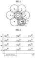
Referring first to Fig. 1, a first embodiment (Embodiment 1) of
the mobile communication system according to the present invention
will be described. Fig. 1 conceptually illustrates the mobile
communication system according to Embodiment 1 of the present
invention. Reference numeral 30 denotes a first coverage area, and
31 a second coverage area. Each radio cell 12 is composed of the first
and second coverage areas 30 and 31. In the drawings concerning
mobile stations of the embodiments described later on, the parts
identical with or corresponding to those in the mobile station of the
prior art example depicted in Fig. 12 will be identified by the same
reference numerals and no description will be given thereof; only
parts different from those in Fig. 12 will be described.
Next, the operation of the mobile communication system depicted
in Fig. 1 will be described below.
In Fig. 1 there is depicted an arrangement of the radio cells 12.
Each of the cells 12 indicates the coverage area defined about the
corresponding base station 11 with which the mobile station 10
exchanges data.
In Fig. 1, when the mobile station 10 is in the second coverage
area 31 where the receiving level is high (in the case of the cell B), no
frequency hopping is performed between the mobile station 10 and
the base station 11. When the mobile station 10 is in the first
coverage area 30 where the receiving level is low (in the case of the
cell A), frequency hopping is performed between the mobile station
10 and the base station 11. That is, in the mobile communication
system according to Embodiment 1, it is determined, based on the
receiving level of a signal received by the mobile station 10 or the
base station 11 at a certain frequency , whether or not the mobile
station 10 performs frequency hopping with respect to the base
station 10. The receiving level herein mentioned is the power level
concerning the received power of the received signal.
Turning next to Fig. 2, firstly seven hopping sequences
z1 to z7 that are provided for the cell A will be described, for
example, in the case where cell A is assigned frequencies F1, F2,
F3 and F4. Let it be assumed that first through fourth mobile stations
M1 to M4 are present in the cell A. The abscissa represents time.
Suppose that the mobile stations M1, M2, M3 and M4 are
assigned the hopping sequences z1, z2, z3 and z4, respectively.
Furthermore assume that data of a burst B1 output from each of the
mobile stations M1 to M4 is received by the base station 11, or that
data output from the base station 11 is received by each of the mobile
stations M1 to M4 at the timing of the burst B1. For example, when
the receiving level is high between the mobile station M1 and the
base station 10 and hence the transmission quality is high, the mobile
station M1 still uses the frequency F1 at the timing of the next burst
B2, too. The receiving level concerning a frequency signal between
the mobile station M1 and the base station 11 is observed in the
mobile station 11 or the base station 10. When the frequency
hopping in the mobile station M1 is interrupted, the mobile station
M1 will be located in the second coverage area 31 close to the base
station 11.
On the other hand, when the frequency signal receiving level is
not so high, for example, between the mobile station M2 and the base
station 11 and hence the transmission quality is low, the frequency
that the mobile station M1 uses in the hopping period concerning the
next burst B2 is switched to the frequency F2. Further with respect to mobile
stations M3 and M4, when the transmission quality is low, the
mobile station M3 is switched from the frequency F3 to F4 and the
mobile station M4 from the frequency F4 to F2. In the case where the
transmission quality is high with respect to the mobile station M1 and
no frequency hopping is performed therein, the base station 11
assigns the mobile stations M2 to M4 the new hopping sequences z5
to z7 that do not contain the frequency F1 to be used by the mobile
station M1, and causes them to perform frequency hopping.
Let it be assumed that the mobile station M2 is assigned the
hopping sequence z5, the mobile station M3 the hopping sequence z6
and the mobile station M4 the hopping sequence z7. The mobile
stations M2 to M4 perform frequency hopping based on the hopping
sequences z5 to z7 assigned to them, respectively, unless the receiving
level in the mobile station M1 falls short of a predetermined level.
When performing the frequency hopping, the mobile stations M2 t M4
are present in the first, coverage area 30 remote from the base station
11.
The hopping sequences z1 to z7 are prepared so that the same
frequency will not be used in the mobile stations M1 to M4 at the
same time. The received level of a signal transmitted between the
mobile stations M1 to M4 and the base station 11 is strongly affected
by geographical features. On account of this, the first and second
coverage areas 30 and 31, which are defined by the received level
of a signal do not always become concentric as depicted in Fig. 1.
When the received level of a signal transmitted between the
mobile stations M1 to M4 and the base station 11 is very high, the
transmission power of a signal that is output from each of the mobile
stations M1 to M4 and the base station 11 may be reduced to such an
extent as not to involve frequency hopping.
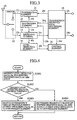
Referring now to Fig. 3, the construction of the mobile station 10
forming the mobile communication system according to Embodiment 1
will be described. Fig. 3 illustrates in block form the mobile station
10. In Fig. 3 the constituents identical with those in the conventional
mobile station 10 depicted in Fig. 15 are identified by the same
reference numerals and no description will be given of them.
In Fig. 3, reference numeral 40 denotes a level detecting part,
which is connected to the receiving part 23 and the control part 26.
Reference numeral 40r denotes level information about a received
signal of a frequency received from the base station 11, which information
is provided from the receiving part 23 to the level detecting part 40.
Reference numeral 40t denotes level detected data, which is provided
from the level detecting part 40 to the control part 26. The level
detecting part 40 detects the received level of the received signal
based on the level information 40r input thereinto. And the level
detecting part 40 outputs the level detected data 40t based on the
detected received level.
Next, a description will be given of the operation of the mobile
station 10 that forms the mobile communication system depicted in
Fig. 3. The level information 40r is input into the level detecting part
40 via the antenna 20, the switch 22 and the receiving part 23. Based
on the level information 40r input thereinto, the level detecting part
40 detects the received level of the signal received by the mobile
station 10 or the base station 11. Then, the level detecting part 40
supplies the control part 26 with the level detected data 40t based on
the input level information 40r.
Based on the level detected data 40t input thereinto, the control
part 26 makes a check to see if the detected level exceeds a
predetermined threshold value. When the detected level is above the
predetermined threshold value, no frequency hopping will take place
between the mobile station 10 and the base station 11. When the
detected level is below the predetermined threshold value, frequency
hopping is performed between the mobile station 10 and the base
station 11. In the latter case, the synthesizer part 25 switches, for
example, the first frequency to the second one, depending on the first
switching data 26t that is provided from the control part 26.
The timing for the frequency switching by the synthesizer part
25 is determined by the timing signal 24g that is provided from the
transmission/receive data processing part 24. The first switching data 26t
that is provided from the control part 26 is determined based on the
hopping sequence data 26r also available from the transmission/receive data
processing part 24. Further, it is considered that the frequency
hopping is carried out when the received level of the received signal
is below the predetermined threshold value as well as when the
former does not exceed the latter. While in Embodiment 1 the mobile
station performs the frequency switching after detecting the received
level, the base station may also perform the detection of the received
level and the frequency switching in this order. It is also possible
that the mobile station detects the received level and indicates the
detection result to the base station, causing it to perform the
frequency switching. Alternatively, the base station may detect the
received level first and then indicate the detection result to the
mobile station, causing it to perform the frequency switching.
Turning next to Fig. 4, the operation of the control part 26 of the
mobile station 10 in Fig. 3 will be described. Fig. 4 is a flowchart
depicting the operation of the control part 26 of the mobile station 10
forming the mobile communication system according to Embodiment
1.
In step S1001 the control part 26 receives the level detected data
40t and the hopping sequence data 26r. Step S1001 is followed by
step S1002.
In step S1002, based on the level detected data 40t input
thereinto, the control part 26 makes a check to determine if the level
of the received wave exceeds a predetermined threshold value. When
the level of the received wave is above the predetermined threshold
value, the procedure goes to step S1003. When the level of the
received wave is below the predetermined threshold value, the
procedure proceeds to step S1004.
In step S1003 the control part 26 determines that no frequency
hopping be carried out, and supplies the synthesizer part 25 with the
first switching data indicating the frequency being used at that time.
The control part 26 terminates a sequence of processing steps with
step S1003.
In step S1004 the control part 26 determines that frequency
hopping be carried out, then determines the frequency to be switched
by the frequency hopping based on the hopping sequence data 26r
received from the send/receive data processing part 24, and supplies
the synthesizer part 25 with the first switching data 26t indicating
the thus determined frequency. The control part 16 terminates a
sequence of processing steps with step S1004.
As described above, the mobile communication system of this
embodiment determines whether or not to perform frequency
hopping between the mobile station 10 and the base station 11, based
on the receiving level of the received wave that is a signal of a
frequency received by the mobile station 10 or the base station 11
from the latter or the former. When the receiving level of the
received wave is low, frequency hopping is carried out, whereas when
the receiving level is high, no frequency hopping takes place.
Accordingly, frequency hopping is performed for the mobile station
10 of a low receiving level to switch the frequency being used therein
to facilitate communications at a higher receiving level. For the
mobile station 10 that already has a high receiving level and hence
has high transmission performance, no frequency hopping is carried
out and the mobile station 10 keeps on high-quality, high-reliability
communications with the base station 11.
The mobile communication system according to this embodiment
permits reduction of the sending power of a signal that is sent from
the mobile station 10 or the base station 11 when the receiving level
of the received wave is high. Hence, it is possible to suppress
interference between the above-mentioned send signal and a signal
that is output from a mobile or base station in the neighboring
repetition area which uses the same frequency as that in the above.
In the mobile communication system according to this
embodiment, since frequency hopping is carried out for the mobile
station 10 that is low in the receiving level of the received wave, a
frequency diversity effect is produced, providing for enhanced
received wave vs. same frequency interference power ratio. This
allows ease in establishing communications at a higher receiving level,
ensuring high-quality, high-reliability communications between the
base and the mobile station.
EMBODIMENT 2
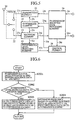
A second embodiment (Embodiment 2) of the present invention
will be described below with reference to Fig. 5. Fig. 5 illustrates in
block form the mobile station 10 that forms the mobile
communication system according to Embodiment 2. The mobile
communication system of this embodiment observes the receiving
level of an interference wave that is a received signal of a frequency
different from that of the signal sent from the base station 11, and
performs frequency hopping based on the result of observation.
In Fig. 5, reference numeral 41 denotes an interference wave
level detecting part, which is connected to the receiving part 23 and
the control part 26. Reference numeral 41r denotes interference
wave level information, which is provided from the receiving part 23
to the interference wave level detecting part 41. Reference numeral
41t denotes interference wave level detected data, which is provided
from the interference wave level detecting part 41 to the control part
26. The interference wave level detecting part 41 detects the
interference wave receiving level based on the interference wave
level information 41r input there into. Then, the interference wave
level detecting part 42 supplies the control part 26 with the
interference wave level detected data 41t based on the detected
receiving level.
Next, a description will be given of the operation of the mobile
station 10 that forms the mobile communication system depicted in
Fig. 5
In Fig. 5, the interference wave level information 41r is input
into the interference wave level detecting part 41 via the antenna 20,
the switch 22 and the receiving part 23. Based on the interference
wave level information 41r input thereinto, the interference wave
level detecting part 41 detects the receiving level of the interference
wave received by the mobile station 10 or the base station 11. Then
the interference wave level detecting part 41 provides to the control
part 26 the interference wave level detected data 41r based on the
input interference wave level information 41r.
Based on the interference wave level detected data 41t input
thereinto, the control part 26 makes a check to determine if the
detected interference wave level exceeds a predetermined threshold
value. When the detected interference wave level does not exceed
the predetermined threshold value, no frequency hopping takes place
between the mobile station 10 and the base station 11. When the
detected interference wave level exceeds the predetermined
threshold value, frequency hopping is carried out between the mobile
station 10 and the base station 11. When the frequency hopping is
performed, the synthesizer part 25 switches, for example, the first
frequency to the second one, based on the first switching data 26t
provided from the control part 26.
The timing for the frequency switching by the synthesizer part
25 is determined by the timing signal 24g that is provided from the
send/receive data processing part 24. The first switching data 26t
that is provided from the control part 26 is determined using the
hopping sequence data 26r also available from the send/receive data
processing part 24. The frequency hopping between the mobile
station 10 and the base station 11 may also be carried out through the
combined use of the receiving level of the received wave and the
interference wave receiving level.
That is, the frequency hopping takes place in the case where the
receiving level of the received wave and the interference wave
receiving level are both low, where the receiving level of the received
wave is low but the interference wave receiving level is high, or
where the receiving level of the received wave and the interference
wave receiving level are both high. It is also considered that the
frequency hopping is carried out when the interference wave
receiving level is above the predetermined threshold value as well as
when the former is equal to the latter. While in Embodiment 2 the
mobile station performs the frequency switching after detecting the
receiving level, the base station may also perform the detection of the
interference wave receiving level and the frequency switching in this
order. It is also possible that the mobile station detects the
interference wave receiving level and indicates the detection result to
the base station, causing it to perform the frequency switching.
Alternatively, the base station may detect the interference wave
receiving level first and then indicate the detection result to the
mobile station, causing it to perform the frequency switching.
Turning next to Fig. 6, the operation of the control part 26 in the
mobile communication system of Embodiment 2 depicted in Fig. 3 will
be described. Fig. 6 is a flowchart depicting the operation of the
control part 26 of the mobile station 10 forming the mobile
communication system according to Embodiment 2.
In step S2001 the control part 26 receives the interference wave
level detected data 41t and the hopping sequence data 26r. Step
S2001 is followed by step S2002.
In step S2002, based on the interference wave level detected
data 41t input thereinto, the control part 26 makes a check to
determine if the level of the received wave exceeds a predetermined
threshold value. When the interference wave level is below the
predetermined threshold value, the procedure proceeds to step
S2004. When interference wave level is above the predetermined
threshold value, the procedure goes to step S2003.
In step S2003 the control part 26 determines that no frequency
hopping be carried out, and supplies the synthesizer part 25 with the
first switching data indicating the frequency being used at that time.
A sequence of operations by the control part 26 is completed with
step S2003.
In step S2004 the control part 26 determines that the frequency
hopping be carried out, then determines the frequency to be switched
by the frequency hopping based on the hopping sequence data 26r
received from the send/receive data processing part 24, and supplies
the synthesizer part 25 with the first switching data 26t indicating
the thus determined frequency. A sequence of operations by the
control part 26 terminates with step S2004.
As described above, the mobile communication system of this
embodiment determines whether or not to perform frequency
hopping between the mobile station 10 and the base station 11, based
on the receiving level of the interference wave that is a signal of a
frequency different from that of a signal received by the mobile
station 10 or the base station 11 from the latter or the former. When
the interference wave receiving level low, frequency hopping is
carried out, whereas when the interference wave receiving level is
high, no frequency hopping takes place. Accordingly, frequency
hopping is performed for the mobile station 10 of a high interference
wave receiving level to switch the frequency being used therein to
facilitate communications at a higher receiving level. For the mobile
station 10 that is low in the receiving level of the received wave,
frequency hopping is carried out to switch the frequency being used
by the mobile station 10, enabling it to communicate with the base
station 11 at a higher receiving level. For the mobile station 10 of a
low interference wave receiving level, this system offers an excellent
transmission quality with a low interference wave receiving level and
an enhanced received signal vs. same frequency interference power
ratio, ensuring high-quality, high-reliability communications between
the mobile station 10 and the base station 11.
With the mobile communication system according to this
embodiment, even in the case of the mobile station high in the
receiving level of the received wave, frequency hopping is carried out
based on the interference wave receiving level, switching the
frequency at which the mobile station 10 and the base station 11
communicate with each other. This breaks up the influence of
interference power by an arbitrary frequency and averages the
interference power that each mobile station 10 suffers.
EMBODIMENT 3
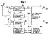
Turning now to Fig. 7, another embodiment of the mobile station
10 in the mobile communication system according to the present
invention will be described below. Embodiment 3 depicted in Fig. 7 is
directed to a mobile communication system that generates a hopping
sequence and performs frequency hopping based on the hopping
sequence.
Fig. 7 illustrates in block form the mobile station 10 that has a
hopping sequence according to Embodiment 3. In Fig. 7, reference
numeral 42 denotes a frequency candidate monitoring part, which is
connected to the receiving part 23 and a hopping sequence control
part 43. The hopping sequence control part 43 is connected to the
frequency candidate monitoring part 42 and the synthesizer part 25.
Reference numeral 42r denotes frequency candidate information,
which is input into the frequency candidate monitoring part 42 via
the receiving part 23. The frequency candidate information 42r is
information that is used to indicate one of given frequencies to each
radio cell. Reference numeral 42t denotes hopping sequence
candidate data, which is provided from the frequency candidate
monitoring part 42 to the hopping sequence control part 43. The
frequency candidate monitoring part 42 makes a check to if the
frequency based on the frequency candidate information 42r satisfies
given requirements. Based on the result of this check, the frequency
candidate monitoring part 42 outputs the hopping sequence candidate
data 42t.
Reference numeral 43t denotes second switching data, which is
provided from the hopping sequence control part 43 to the
synthesizer part 25. Based on the second switching data 43t input
thereinto, the synthesizer part 25 switches, for example, the first
frequency to the second one. The second switching data 43t is output
from the hopping sequence control part 43 based on the hopping
sequence candidate data 42t input there into.
Next, a description will be given of a hopping sequence
generating operation of the mobile station 10 in the mobile
communication system of Fig. 7. The frequency candidate information
42r is input into the frequency candidate monitoring part 42 via the
antenna 20, the switch 22 and the receiving part 23. Based on the
frequency candidate information 42r input thereinto, the frequency
candidate monitoring part 42 determines the frequency to be
switched at the timing at which the frequency hopping is carried out
next, and provides to the hopping sequence control part 43 the
hopping sequence candidate data 42t indicative of the determined
frequency.
Based on the hopping sequence candidate data 42t input
thereinto, the hopping sequence control part 43 provides to the
synthesizer part 25 the second switching data 43t that designates the
same frequency as that specified by the hopping sequence candidate
data 42t. Based on the second switching data 43t provided from the
hopping sequence control part 43 and the timing signal 24g from the
send/receive data processing part 24, the synthesizer part 25
provides to the transmitting part 21 the transmitting frequency data
25t for switching the frequency to be output therefrom, or provides
the received frequency data 25r to the receiving part 23. The
hopping sequence control part 43 sequentially records in a memory or
similar recording part all pieces of the hopping sequence candidate
data 42t input thereinto.
When a predetermined number of such hopping sequence
candidate data 42t are recorded, the hopping sequence control part 43
independently generates a hopping sequence from the plurality of
recorded pieces of hopping sequence candidate data 42t and holds the
hopping sequence. The hopping sequence control part 43 uses its
generated hopping sequence to determine the frequency to be
switched at the timing of the next frequency hopping, and indicates
the determined frequency to the synthesizer part 25 by sending
thereto the second switching data 43t. The mobile communication
system performs the frequency hopping based on the hopping
sequence generated by the hopping sequence control part 43.
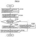
Next, a description will be given, with reference to Fig. 8, of
operations of the frequency candidate monitoring part 42 and the
hopping sequence control part 43 of the mobile station 10 depicted in
Fig. 7. Fig. 8 is a flowchart showing the operations of the frequency
candidate monitoring part 42 and the hopping sequence control part
43 forming the mobile communication system according to
Embodiment 3.
In step S3001 the frequency candidate monitoring part 42
receives the frequency candidate information 42r from the receiving
part 23. The frequency candidate monitoring part 42 determines
from the frequency candidate information 42r input thereinto the
frequency to be switched at the timing of the next frequency hopping,
and provides to the hopping sequence control part 43 the hopping
sequence candidate data 42t indicative of the determined frequency.
Step S3001 is followed by step S3002.
In step S3002 the hopping sequence control part 43 records the
hopping sequence candidate data 42t input thereinto. When the
number of recorded hopping sequence candidate data 42t reaches a
predetermined value, the hopping sequence control part 43 generates
a hopping sequence from the plurality of recorded hopping sequence
candidate data 42t. Step S3002 is followed by step S3003.
In step S3003 the hopping sequence control part 43 makes a
check to determine if a hopping sequence has been completely
generated from the predetermined number of recorded hopping
sequence candidate data 42t. If so, the procedure proceeds to step
S3004, and if not, then the procedure goes to step S3005.
In step S3004 the hopping sequence control part 43 determines
from its generated hopping sequence the frequency to be switched at
the timing of the next frequency hopping. Step S3004 is followed by
step S3006.
In step S3005 the hopping sequence control part 43 determines,
from the hopping sequence candidate data 42t input thereinto, the
frequency to be switched at the timing of the next frequency hopping.
Step S3005 is followed by step S3006.
In step S3006 the hopping sequence control part 43 indicates its
determined frequency to the synthesizer 24 by sending thereto the
second switching data 43t. A sequence of operations ends with step
S3006.
Referring next to Fig. 9, a detailed description will be given of the
operation by which the frequency candidate monitoring part 42
determines the frequency to be switched by frequency hopping in
step S3001. Fig. 9 is a flowchart for explaining the process in step
S3001 in the Fig. 8 flowchart by which the frequency candidate
monitoring part 42 determines the frequency to be switched by
frequency hopping.
In step S4001 the frequency candidate monitoring part 42
observes or monitors the frequency candidate information 42r
starting at a frequency number i (where i=0) so as to sequentially
observe or monitor receiving levels concerning frequencies assigned
predetermined frequency numbers. Step S4001 is followed by step
S4002.
In step S4002 the frequency candidate monitoring part 42
detects the receiving level Ri of the frequency number i, and
compares the detected receiving level Ri with a preset threshold value
Ra of the receiving level. When the receiving level Ri exceeds the
threshold value Ra, the procedure proceeds to step S4005. When the
receiving level Ri falls short of the threshold value Ra, the procedure
goes to step S4003. In step S4003 the frequency candidate
monitoring part 42 increments the frequency number i. Step S4003 is
followed by step S4004.
In sep S4004 the frequency candidate monitoring part 42 makes
a check to determine if the incremented frequency number i exceeds
the frequency number N that is a given number of frequencies. When
the frequency number i exceeds the frequency number N, the
procedure returns to step S4001. When the frequency number i does
not exceed the frequency number N, the procedure goes back to step
S4002.
In step S4005 the frequency candidate monitoring part 42
determines the frequency that is switched at the timing of the next
frequency hopping, and provides to the hopping sequence control part
43 the hopping sequence candidate data 42t indicative of the
determined frequency. A series of operations by the frequency
candidate monitoring part 42 ends with step S4005.
While in this embodiment the frequency to be switched by
frequency hopping is determined based on the frequency receiving
level, the frequency to be switched may also be determined using the
interference wave receiving level instead of using the frequency
receiving level. When the mobile station 10 or the base station 11 is
high in the frequency receiving level or low in the interference wave
receiving level, stable communications are established between the
mobile station 11 and the base station 10.
As described above, the mobile communication system according
to this embodiment uses, for frequency hopping, a hopping sequence
generated through utilization of the hysteresis of each mobile station
in the past. Hence, a mobile station of a high frequency of use in a
predetermined coverage area need not perform frequency hopping
based on a predetermined hopping sequence in which there are
arranged frequencies whose receiving levels are not always high in
the coverage area; but instead such a mobile station is allowed to
perform frequency hopping based on its own hopping sequence in
which there are arranged frequencies of high receiving levels in the
coverage area. This provides relatively stable communications
between the mobile station and the base station.
EMBODIMENT 4
Turning next to Fig. 10, another embodiment of the mobile
station in the mobile communication system according to the present
invention will be described below. Fig. 10 is a flowchart explaining
the operation by which the frequency candidate monitoring part 42
determines the frequency to be switched by frequency hopping in a
manner different from that described above in respect of step S3001
in the Fig. 8 flowchart. In other words, Fig. 8 is a flowchart for
explaining the operation of the frequency candidate monitoring part
42 for determining the frequency to be switched by frequency
hopping in step S3001 in the Fig. 8 flowchart.
In step S5001 in Fig. 10 the frequency candidate monitoring par
42 observes or monitors the frequency candidate information 42r
starting at a frequency number i (where i=0) so as to sequentially
observe or monitor receiving levels concerning frequencies assigned
predetermined frequency numbers. Step S5001 is followed by step
S5002.
In step S5002 the frequency candidate monitoring part 42
records, as the maximum receiving level Rmax, the receiving level Ri
of a predetermined frequency assigned the frequency number i. Step
S5002 is followed by step S5003.
In step S5003 the frequency candidate monitoring part 42
increments the frequency number i. Step S5003 is followed by step
S5004.
In step S5004 the frequency candidate monitoring part 42 makes
a check to determine if the incremented frequency number i exceeds
the frequency number N. When the frequency number i exceeds the
frequency number N, the procedure goes to step S5006. When the
frequency number i does not exceed the frequency number N, the
procedure goes to step S5005.
In step S5005 the frequency candidate monitoring part 42
compares the receiving level Ri concerning the predetermined
frequency of the incremented frequency number i with the maximum
receiving level Rmax recorded based on the results of comparison
made so far. When the receiving level Ri exceeds the maximum
receiving level Rmax, the procedure goes back to step S5002. When
the receiving level Ri does not exceed the maximum receiving level
Rmax, the procedure returns to step S5003.
In step S5006 the frequency candidate monitoring part 42
determines the frequency that is switched at the timing of the next
frequency hopping, and provides to the hopping sequence control part
43 the hopping sequence candidate data 42t indicative of the
determined frequency. A series of operations by the frequency
candidate monitoring part 42 ends with step S5006.
While in this embodiment the frequency to be switched by
frequency hopping is determined based on the frequency receiving
level, the frequency to be switched may also be determined using the
interference wave receiving level instead of using the frequency
receiving level.
As described above, the mobile communication system according
to this embodiment uses, for frequency hopping, a hopping sequence
generated through utilization of the hysteresis of each mobile station
in the past. Hence, a mobile station of a high frequency of use in a
predetermined coverage area need not perform frequency hopping
based on a predetermined hopping sequence in which there are
arranged frequencies whose receiving levels are not always high in
the coverage area; but instead such a mobile station is allowed to
perform frequency hopping based on its own hopping sequence in
which there are arranged frequencies of high receiving levels in the
coverage area. This provides relatively stable communications
between the mobile station and the base station.
EMBODIMENT 5
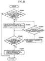
With reference to Fig. 11, another embodiment of the mobile
station 10 for the mobile communication system according to the
present invention will be described below. Fig. 11 is a flowchart for
explaining an operation by which the hopping sequence generated by
the method described above in respect of Embodiment 3 or 4 is
updated with levels or interference levels that are detected when
frequency hopping is carried out based on the hopping sequence. In
other words, Fig. 11 is a flowchart explanatory of the hopping
sequence updating process corresponding to step S3001 in the Fig. 8
flowchart.
In step S6001 in Fig. 11 the frequency candidate monitoring part
42 makes a check to see if the receiving level of a frequency
concerned in the hopping sequence of the mobile station 10 falls short
of the preset threshold value Ra. When the receiving level of the
frequency is below the threshold value Ra, the procedure goes to step
S6002. When the receiving level does not fall short of the threshold
value Ra, the procedure ends.
In step S6002 the frequency candidate monitoring part 42
observes or monitors the frequency candidate information 42r
starting at the frequency number i (where i=0) so as to sequentially
observe or monitor the receiving levels concerning frequencies
assigned predetermined frequency numbers. Upon completion of step
S6002, the procedure goes to step S6003.
In step S6003 the frequency candidate monitoring part 42 makes
a check to see if the receiving level Ri concerning a frequency of a
certain frequency number i exceeds the preset threshold value Ra.
When the receiving level Ri of that frequency exceeds the threshold
value Ra, the procedure goes to step S6006. When the receiving level
does not exceed the threshold value Ra, the procedure goes to step
S6004.
In step S6004 the frequency candidate monitoring part 42
increments the frequency number i. Upon completion of step S6004,
the procedure goes to step S6005.
In step S6005 the frequency candidate monitoring part 42 makes
a check to determine if the incremented frequency number i exceeds
the frequency number N. When the frequency number i exceeds the
frequency number N, the procedure goes back to step S6002. When
the frequency number i does not exceed the frequency N, the
procedure returns to step S6003.
In step S6006 the frequency candidate monitoring part 42
provides to the hopping sequence control part 43 the hopping
sequence candidate data 42t indicative of the frequency of the
frequency number i concerned. Based on the hopping sequence
candidate data input thereinto, the hopping sequence control part 43
updates data concerning the corresponding frequency in the hopping
sequence that the mobile station 10 uses. A sequence of hopping
sequence updating operations terminates with step S6006.
In the flowchart described above, the frequency in
the hopping sequence at which the predetermined receiving level is
not reached is switched to a frequency which satisfies the
requirement. In this case, however, such a frequency at which the
predetermined receiving level is not reached may be a frequency of
the receiving level higher than any other observable frequencies. The
frequency hopping is carried out based on the predetermined hopping
sequence until the original hopping sequence is generated.
The original hopping sequence may be updated upon each
elimination of an element forming the hopping sequence. In this
instance, the predetermined hopping sequence is used from the time
when one element of the original hopping sequence is removed
therefrom to the time when the hopping sequence is updated with a
new element. The original hopping sequence need not always be
updated until a predetermined number of elements are eliminated
therefrom. In this case, the hopping sequence with some elements
removed therefrom is used intact until a predetermined number of
elements are eliminated, and the predetermined hopping sequence is
used from the time when the predetermined number of elements are
eliminated to the time when the original hopping sequence is updated
with a required number of new elements. It is possible to use
different criteria for selecting arbitrary frequencies for forming the
original hopping sequence and for eliminating therefrom arbitrary
frequencies.
As described above, the mobile communication system according
to this embodiment uses, for frequency hopping, a hopping sequence
generated through utilization of the hysteresis of each mobile station
in the past. Hence, a mobile station of a high frequency of use in a
predetermined coverage area need not perform frequency hopping
based on a predetermined hopping sequence in which there are
arranged frequencies whose receiving levels are not always high in
the coverage area; but instead such a mobile station is allowed to
perform frequency hopping based on its own hopping sequence in
which there are arranged frequencies of high receiving levels in the
coverage area. This provides relatively stable communications
between the mobile station and the base station.
Moreover, since the mobile communication system according to
this embodiment uses, for frequency hopping, a hopping sequence
generated through utilization of the hysteresis of each mobile station
in the past, it is possible to obtain more actually usable channels than
in the case of a fixed frequency assignment system in which
predetermined hopping sequence is assigned to each frequency.
Further, according to the mobile communication system of this
embodiment, the frequency in the original hopping sequence of this
system at which the receiving level of the received wave is below the
predetermined threshold value is replaced with that one of given
frequencies at which the receiving level of the received wave exceeds
the predetermined threshold value, by which the hopping sequence is
updated. This ensures relatively stable, highly reliable
communications between the mobile and the base station.
Additionally, according to the mobile communication system of
this embodiment, the frequency in the original hopping sequence of
this system at which the interference wave receiving level exceeds a
predetermined threshold value is substituted for that one of given
frequencies at which the interference wave receiving level falls short
of the predetermined threshold value, by which the hopping sequence
is updated. This ensures relatively stable, highly reliable
communications between the mobile and the base station.
It is to be understood that the preferred embodiments of the
present invention described above are construed as being merely
illustrative of the invention and that many modifications and
variations may be effected without departing from the spirit and
scope of the claims appended hereunto.