EP0882639A2 - Component for bodywork construction of motor vehicles and its method of manufacuture - Google Patents
Component for bodywork construction of motor vehicles and its method of manufacuture Download PDFInfo
- Publication number
- EP0882639A2 EP0882639A2 EP98107615A EP98107615A EP0882639A2 EP 0882639 A2 EP0882639 A2 EP 0882639A2 EP 98107615 A EP98107615 A EP 98107615A EP 98107615 A EP98107615 A EP 98107615A EP 0882639 A2 EP0882639 A2 EP 0882639A2
- Authority
- EP
- European Patent Office
- Prior art keywords
- body frame
- frame component
- holes
- hole
- component according
- Prior art date
- Legal status (The legal status is an assumption and is not a legal conclusion. Google has not performed a legal analysis and makes no representation as to the accuracy of the status listed.)
- Granted
Links
Images

Classifications
-
- B—PERFORMING OPERATIONS; TRANSPORTING
- B62—LAND VEHICLES FOR TRAVELLING OTHERWISE THAN ON RAILS
- B62D—MOTOR VEHICLES; TRAILERS
- B62D21/00—Understructures, i.e. chassis frame on which a vehicle body may be mounted
- B62D21/15—Understructures, i.e. chassis frame on which a vehicle body may be mounted having impact absorbing means, e.g. a frame designed to permanently or temporarily change shape or dimension upon impact with another body
Definitions
- the invention relates to a body frame component for the body of a motor vehicle, wherein the body frame member has a specific shape and for receiving at least one force acting on the body frame component is formed, wherein due to the specific shape of the body frame component when absorbing this force different within different areas of the body frame component Load or stress conditions exist, especially in a first area high and, in a second area, lower load or stress conditions occur.
- the invention further relates to a method for producing a Body frame component for the body of a motor vehicle, the Body frame component made of a substantially flat material by reshaping a specific form that can be built into a body is formed and that Body frame component - when installed in the body - at least one the body frame component absorbs the force acting, when absorbing this force due to the specific shape of the body frame component within different Areas of the body frame component different load or Stress states are generated.
- body frame components known that can be manufactured in different ways, so that Total weight of the motor vehicle is as low as possible. So that these Body frame components that can absorb the forces acting on them have the Body frame components on the one hand a specific shape and their purpose a corresponding material thickness.
- the material thickness is in different areas of the body frame component depending on the load or Tension states are designed differently. So in areas with high stress or Stress states also provide a much greater "material thickness" than in Areas with lower stress or stress conditions.
- structural elements to be arranged separately are known in the prior art (DE-OS 25 58 332 and EP 0 633 182 B1), which are designed as perforated plates or steel grids and especially attached to the inside of vehicle doors or hoods to increase the mechanical strength or rigidity of a vehicle door. These structural elements are applied to the corresponding areas of a vehicle door glued or connected to the sheet metal of the vehicle door by cold forming.
- the invention is therefore based on the object of possibly having a body frame component to specify little weight and a method for its production, in which no large Manufacturing tolerances and as few weak points as possible occur, the process for its production can be carried out without much time.
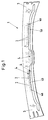
- the Body frame component 1 shows a body frame component 1, namely as a roof rack support trained body component 1 for the body of a motor vehicle.
- the Body frame component 1 has a specific shape typical of a roof rack support and is designed to absorb the forces acting on a roof rack support So when installed, a load-bearing part of the body. Because of the specific Shape of the body frame component 1 exist when these forces are absorbed, that is, then if the body frame component 1 designed as a roof rack support in the roof area a motor vehicle is installed, within different areas 3 and 4 (4a, 4b) of the Body frame component 1 different load or tension conditions.
- first area 3 namely in particular in the edge area, high and in one second area 4 (4a, 4b), namely in particular in the central area of the roof rack support, lower stress or stress conditions.
- the occurring load or Tension states can vary widely in different areas Be pronounced. On the one hand, this depends on the specific form of the Body frame component 1, on the other hand from those in the different areas occurring forces or force components, for example, transverse forces normal forces or bending forces or moments.
- a weight saving on the body frame component 1 is realized in that Area 4 (4a, 4b) of the lower load or tension state for reduction of the material of the body frame component 1 at least one through hole 2, in which Body frame component 1 shown in FIG. 1 has a plurality of through holes 2 are.
- a certain hole pattern is formed through the through holes 2, so that the weight of the body frame component 1 according to that acting on the body frame component 1 Loads is optimized.
- the body frame component 1 by the formation of the Through holes 2 to reduce the material everywhere a substantially the same Can have material thickness.
- the body frame member 1 can thereby in a simple way by one or more forming processes from a flat Material, in particular made of metal boards.
- the through holes 2 can have a certain one Have shape, for example, the through holes 2 can be circular, triangular or be square. Furthermore, the through holes 2 - depending of the occurring loads - have different specific hole diameters. As a result, the shape and the hole diameter of the through holes 2 can be the same as in FIG the body frame component 1 occurring loads are adjusted. Furthermore is determined by the hole spacing of the through holes 2 with each other and a certain one Hole pattern the body frame component 1 according to the loads that occur optimized. For example, the through holes 2 in certain rows - as shown in Fig. 1 shown - can be arranged.
- the through holes 2 are at a certain distance from one Force introduction point of the body frame component 1, in particular in a certain one Distance to hinges, struts, functional surfaces or knots provided, as these areas directly adjacent to a force application point (here areas 3) of the Body frame component 1 are more stressed.
- functional areas can in particular contact surfaces for connection to other components as well as reference surfaces e.g. serve to position the component during production.
- the body frame component 1 shown in FIG. 1 is made of metal, namely from a flat metal plate with constant sheet thickness.
- the Process for producing the body frame component 1 are explained in more detail, whereby - in the end - a three-dimensional body frame component 1 is produced, the - As can be seen schematically from Fig. 1 - a higher area 4a and one lower-lying area 4b has:
- Fig. 2 shows a metal plate 5, which are formed with the help of a forming process can that the body frame member 1 shown in Fig. 1 with that for the roof rack support necessary specific form arises.
- Through holes 2 vzw. a hole diameter of 3 mm and a hole spacing of 3 mm.
- the body frame component 1 in the method for producing a body frame component 1 for the body of a motor vehicle, the body frame component 1 from a essential sheet material formed by the sheet material, usually a Metal board 5, to a specific shape that can be installed inside a body is reshaped.
- the body frame component 1 takes - in the body installed Condition - the forces acting on the body frame component 1, whereby Absorption of these forces due to the specific shape of the body frame component 1 1 different within different areas of the body frame component Load or stress conditions are generated.
- the weight saving for the body frame component 1 and a time saving in the Implementation of the method is realized in that before the forming or during the transformation of the flat material into the specific shape of the Body frame component 1 in the area 4 of the sheet material, in the after Forming - in the installed state of the body frame component 1 - is less Stress or stress condition occurs, at least one through hole 2, here several through holes 2 to reduce the material of the Body frame component 2 are formed.
- the through holes 2 immediately before the forming process for example in a press line at Trimming a metal plate 5 are introduced, so that in addition to punching with a Punching tool no additional process step to form the through holes 2 more is needed.
- the through holes 2 could also during the Forming process are introduced accordingly.
- the procedure is vzw. realized with computer support.
- the forming process is carried out by deep drawing.
- the through holes 2 can be cut prior to deep drawing when trimming the flat Material, here the metal plate 5 shown in FIG. 2 are formed. It is also conceivable that the through holes 2 during deep drawing in the sheet material be formed. The tools necessary for deep drawing could be used for this be trained accordingly.
- the body frame component 1 made from a metal plate 5 has a substantially constant thickness as this is the further treatment and Processing - just without having to consider changes in thickness - essential simplified.
Landscapes
- Engineering & Computer Science (AREA)
- Chemical & Material Sciences (AREA)
- Combustion & Propulsion (AREA)
- Transportation (AREA)
- Mechanical Engineering (AREA)
- Body Structure For Vehicles (AREA)
Abstract
Description
Die Erfindung betrifft ein Karosserierahmenbauteil für die Karosserie eines Kraftfahrzeuges, wobei das Karosserierahmenbauteil eine spezifische Form aufweist und zur Aufnahme mindestens einer auf das Karosserierahmenbauteil wirkenden Kraft ausgebildet ist, wobei aufgrund der spezifischen Form des Karosserierahmenbauteiles bei Aufnahme dieser Kraft innerhalb verschiedener Bereiche des Karosserierahmenbauteiles unterschiedliche Belastungs- bzw. Spannungszustände existieren, insbesondere in einem ersten Bereich hohe und in einem zweiten Bereich geringere Belastungs- bzw. Spannungszustände auftreten.The invention relates to a body frame component for the body of a motor vehicle, wherein the body frame member has a specific shape and for receiving at least one force acting on the body frame component is formed, wherein due to the specific shape of the body frame component when absorbing this force different within different areas of the body frame component Load or stress conditions exist, especially in a first area high and, in a second area, lower load or stress conditions occur.
Weiterhin betrifft die Erfindung ein Verfahren zum Herstellen eines Karosserierahmenbauteiles für die Karosserie eines Kraftfahrzeuges, wobei das Karosserierahmenbauteil aus einem im wesentlichen flächigem Material durch Umformen zu einer innerhalb einer Karosserie einbaubaren spezifischen Form gebildet wird und das Karosserierahmenbauteil - im in der Karosserie eingebauten Zustand - mindestens eine auf das Karosserierahmenbauteil wirkende Kraft aufnimmt, wobei bei Aufnahme dieser Kraft aufgrund der spezifischen Form des Karosserierahmenbauteiles innerhalb verschiedener Bereiche des Karosserierahmenbauteiles unterschiedliche Belastungs- bzw. Spannungszustände erzeugt werden.The invention further relates to a method for producing a Body frame component for the body of a motor vehicle, the Body frame component made of a substantially flat material by reshaping a specific form that can be built into a body is formed and that Body frame component - when installed in the body - at least one the body frame component absorbs the force acting, when absorbing this force due to the specific shape of the body frame component within different Areas of the body frame component different load or Stress states are generated.
Im Stand der Technik, von dem die Erfindung ausgeht, sind Karosserierahmenbauteile bekannt, die auf unterschiedliche Arten hergestellt werden können, damit das Gesamtgewicht des Kraftfahrzeuges möglichst gering ist. Damit diese Karosserierahmenbauteile die auf sie wirkenden Kräfte aufnehmen können weisen die Karosserierahmenbauteile einerseits eine ihrem Zweck entsprechende spezifische Form und eine entsprechende Materialdicke auf. Die Materialdicke ist in unterschiedlichen Bereichen des Karosserierahmenbauteils in Abhängigkeit der hier auftretenden Belastungs- bzw. Spannungszustände unterschiedlich ausgebildet. So ist in Bereichen mit hohen Belastungs- bzw. Spannungszuständen auch eine weitaus größere "Materialdicke" vorgesehen als in Bereichen mit geringeren Belastungs- bzw. Spannungszuständen.In the prior art, from which the invention is based, are body frame components known that can be manufactured in different ways, so that Total weight of the motor vehicle is as low as possible. So that these Body frame components that can absorb the forces acting on them have the Body frame components on the one hand a specific shape and their purpose a corresponding material thickness. The material thickness is in different areas of the body frame component depending on the load or Tension states are designed differently. So in areas with high stress or Stress states also provide a much greater "material thickness" than in Areas with lower stress or stress conditions.
So werden gewichtssparende Karosserierahmenbauteile bislang mit Hilfe der "tailored-blank"-Technik hergestellt. Hierbei werden verschiedene Metallelemente, meistens Metallbleche mit unterschiedlichen Gefügestrukturen, die zudem unterschiedliche Blechdicken aufweisen, derartig miteinander verschweißt, daß ein Karosserierahmenbauteil mit einer spezifischen Form entsteht. Hierbei weist das Karosserierahmenbauteil in unterschiedlichen Bereichen - aufgrund der verwendeten Metallbleche mit unterschiedlicher Blechdicke - eine unterschiedliche Wandstärke bzw. "Materialdicke" auf. Weiterhin werden derartige Karosserierahmenbauteile mit in verschiedenen Bereichen vorgesehenen unterschiedlichen Wandstärken auch im aufwendigen Druckgußverfahren hergestellt.So far, weight-saving body frame components have been made using the "tailored-blank" technology produced. Here, various metal elements, mostly Metal sheets with different microstructures, which are also different Have sheet thicknesses, welded together such that a body frame component with a specific shape. Here, the body frame component in different areas - due to the metal sheets used with different Sheet thickness - a different wall thickness or "material thickness". Continue to be such body frame components provided in different areas different wall thicknesses also manufactured in the complex die casting process.
Ferner sind im Stand der Technik separat anzuordnende Strukturelemente bekannt (DE-OS 25 58 332 und EP 0 633 182 B1), die als Lochbleche oder Stahlgitter ausgeführt sind und insbesondere an den Innenseiten von Fahrzeugtüren oder Fahrzeughauben befestigt werden, um die mechanische Festigkeit bzw. Steifigkeit einer Fahrzeugtüre zu erhöhen. Diese Strukturelemente werden auf die entsprechenden Bereiche einer Fahrzeugtüre aufgeklebt oder mit dem Blech der Fahrzeugtüre durch Kaltverformung verbunden.Furthermore, structural elements to be arranged separately are known in the prior art (DE-OS 25 58 332 and EP 0 633 182 B1), which are designed as perforated plates or steel grids and especially attached to the inside of vehicle doors or hoods to increase the mechanical strength or rigidity of a vehicle door. These structural elements are applied to the corresponding areas of a vehicle door glued or connected to the sheet metal of the vehicle door by cold forming.
Die bekannten Karosserierahmenbauteile, die mit Hilfe des "tailored-blank"-Verfahrens oder Druckgußverfahrens hergestellt werden, sind einerseits nicht optimal ausgebildet, andererseits sind die Verfahren für deren Herstellung sehr aufwendig. So hat die Praxis gezeigt, daß die mit Hilfe des "tailored-blank"-Verfahrens herzustellenden komplexen Karosserierahmenbauteile, da für deren Herstellung verschiedene Metallbleche mit unterschiedlichen Gefügestrukturen verwendet werden, nur unter hohem Aufwand gefertigt werden können und die entsprechenden Fertigungstoleranzen für das Karosserierahmenbauteil bei dessen Zusammensetzung nur schwer einzuhalten sind. Weiterhin müssen die vorhandenen Schweißnähte nicht nur präzise ausgeführt sein, sondern müssen auch die entsprechenden Kräfte aufnehmen, wobei sie innerhalb des Karosserierahmenbauteils als Schwachstellen existent sind. Im Ergebnis ist das gesamte Verfahren für diese Art der Herstellung äußerst zeitaufwendig. The well-known body frame components using the "tailored-blank" method or Die-casting processes are not optimally designed, on the other hand, the processes for their production are very complex. So has practice demonstrated that the complexes to be produced using the "tailored-blank" process Body frame components, since various metal sheets are used to manufacture them different microstructures are used, manufactured only with great effort can be and the corresponding manufacturing tolerances for the Body frame component with its composition are difficult to adhere to. Furthermore, the existing weld seams not only have to be made precisely, but must also absorb the corresponding forces, being within the Body frame component exist as weak points. The result is the whole Processes for this type of manufacture are extremely time consuming.
Der Erfindung liegt daher die Aufgabe zugrunde, ein Karosserierahmenbauteil mit möglichst wenig Gewicht und ein Verfahren für dessen Herstellung anzugeben, bei dem keine großen Fertigungstoleranzen und möglichst wenig Schwachstellen auftreten, wobei das Verfahren für dessen Herstellung ohne großen Zeitaufwand durchführbar ist.The invention is therefore based on the object of possibly having a body frame component to specify little weight and a method for its production, in which no large Manufacturing tolerances and as few weak points as possible occur, the process for its production can be carried out without much time.
Diese Aufgabe ist für das Karosserierahmenbauteil nun dadurch gelöst, daß in dem Bereich des geringeren Belastungs- bzw. Spannungszustandes zur Reduzierung des Materials des Karosserierahmenbauteiles mindestens ein Durchgangsloch ausgebildet ist.This task is now solved for the body frame component in that in the area the lower load or stress condition to reduce the material of the Body frame component is formed at least one through hole.
Für das Verfahren zur Herstellung des Karosserierahmenbauteils wird die Aufgabe nun dadurch gelöst, daß vor dem Umformen oder während des Umformens des flächigen Materials zu der spezifischen Form des Karosserierahmenbauteiles in dem Bereich des flächigen Materials, in dem nach dem Umformen - in eingebautem Zustand des Karosserierahmenbauteiles - ein geringerer Belastungs- bzw. Spannungszustand auftritt, mindestens ein Durchgangsloch zur Reduzierung des Materials des Karosserierahmenbauteiles ausgebildet wird.The task now becomes for the method for manufacturing the body frame component solved in that before the forming or during the forming of the flat Material to the specific shape of the body frame component in the area of flat material, in which after forming - in the installed state of the Body frame component - a lower load or stress condition occurs, at least one through hole to reduce the material of the Body frame component is formed.
Dadurch, daß nunmehr zur Reduzierung des Materials des Karosserierahmenbauteiles, also zur Gewichtseinsparung mindestens ein Durchgangsloch in einem Bereich niedriger Belastungen bzw. Spannungen ausgebildet wird, werden die oben beschriebenen Nachteile vermieden. Einerseits kann nun auf einfache Weise das für das Karosserierahmenbauteil verwendete Material in geeigneten Bereichen reduziert werden, so daß die bislang mit Hilfe des "tailored-blank"-Verfahrens komplexere Zusammensetzung (durch Blechstücke verschiedener Dicke) des Karosserierahmenbauteiles entfällt. Da keine komplexe Zusammensetzung mehr notwendig ist können nicht nur bessere Toleranzwerte erreicht werden, sondern es entfallen auch die bisher notwendigen - die Schwachstellen bildenden - Schweißnähte. Da bei dem Verfahren zur Herstellung nunmehr mehrere Durchgangslöcher vor dem Umformen oder während des Umformens hergestellt werden können, kann das Verfahren zur Herstellung eines Karosserierahmenbauteiles auch in relativ kurzer Zeit durchgeführt werden.Because now to reduce the material of the body frame component, that is to save weight at least one through hole in an area lower Loads or tensions are formed, the disadvantages described above avoided. On the one hand, this can now be done in a simple manner for the body frame component used material can be reduced in suitable areas, so that with help the "tailored-blank" process more complex composition (through sheet metal pieces different thickness) of the body frame component is eliminated. Because no complex Composition is more necessary not only can better tolerance values be achieved , but also the previously necessary - the weak points - Welds. Since there are now several through holes in the production method can be produced before the forming or during the forming, that can Process for producing a body frame component even in a relatively short time be performed.
Es gibt nun eine Vielzahl von Möglichkeiten, das erfindungsgemäße Karosserierahmenbauteil bzw. das Verfahren zu dessen Herstellung in vorteilhafter Weise auszugestalten und weiterzubilden. Hierfür darf an dieser Stelle auf die dem Patentanspruch 1 und dem Patentanspruch 16 nachgeordneten Patentansprüche verwiesen werden.There are now a multitude of possibilities for the inventive method Body frame component or the method for its production in an advantageous manner to design and develop. For this, the patent claim may be made at this point 1 and claim 16 subordinate claims.
Im übrigen wird nun eine Ausführungsform der Erfindung anhand einer Zeichnung näher erläutert. In der Zeichnung zeigt
- Fig.1
- ein Karosserierahmenbauteil mit einer spezifischen Form gemäß der Erfindung in einer schematischen Darstellung und
- Fig.2
- ein flächiges Material kurz vor dem Umformen zur Herstellung eines Karosserierahmenbauteiles gemäß der Erfindung.
- Fig. 1
- a body frame component with a specific shape according to the invention in a schematic representation and
- Fig. 2
- a flat material shortly before forming to produce a body frame component according to the invention.
Die Fig. 1 zeigt ein Karosserierahmenbauteil 1, nämlich ein als Dachträgerstütze
ausgebildetes Karosseriebauteil 1 für die Karosserie eines Kraftfahrzeuges. Das
Karosserierahmenbauteil 1 weist eine für eine Dachträgerstütze typische, spezifische Form
auf und ist zur Aufnahme der auf eine Dachträgerstütze wirkenden Kräfte ausgebildet, bildet
also im eingebauten Zustand ein tragendes Teil der Karosserie. Aufgrund der spezifischen
Form des Karosserierahmenbauteiles 1 existieren bei Aufnahme dieser Kräfte, also dann
wenn das als Dachträgerstütze ausgebildete Karosserierahmenbauteil 1 im Dachbereich
eines Kraftfahrzeuges eingebaut ist, innerhalb verschiedener Bereiche 3 bzw. 4 (4a,4b) des
Karosserierahmenbauteiles 1 unterschiedliche Belastungs- bzw. Spannungszustände. So
treten in einem ersten Bereich 3, nämlich insbesondere im Randbereich, hohe und in einem
zweiten Bereich 4 (4a,4b), nämlich insbesondere im mittleren Bereich der Dachträgerstütze,
geringere Belastungs- bzw. Spannungszustände auf. Die auftretenden Belastungs- bzw.
Spannungszustände können in den verschiedenen Bereichen sehr unterschiedlich
ausgeprägt sein. Dies ist einerseits abhängig von der spezifischen Form des
Karosserierahmenbauteils 1, andererseits von den in den verschiedenen Bereichen
auftretenden Kräften oder Kraftkomponenten, beispielsweise, Querkräften Normalkräften
oder auch Biegekräften bzw. -momenten.1 shows a body frame component 1, namely as a roof rack support
trained body component 1 for the body of a motor vehicle. The
Body frame component 1 has a specific shape typical of a roof rack support
and is designed to absorb the forces acting on a roof rack support
So when installed, a load-bearing part of the body. Because of the specific
Shape of the body frame component 1 exist when these forces are absorbed, that is, then
if the body frame component 1 designed as a roof rack support in the roof area
a motor vehicle is installed, within
Eine Gewichtseinsparung am Karosserierahmenbauteil 1 ist dadurch realisiert, daß in dem
Bereich 4 (4a,4b) des geringeren Belastungs- bzw. Spannungszustandes zur Reduzierung
des Materials des Karosserierahmenbauteiles 1 mindestens ein Durchgangsloch 2, bei dem
in der Fig. 1 gezeigten Karosserierahmenbauteil 1 mehrere Durchgangslöcher 2 ausgebildet
sind.A weight saving on the body frame component 1 is realized in that
Area 4 (4a, 4b) of the lower load or tension state for reduction
of the material of the body frame component 1 at least one through
Durch die Durchgangslöcher 2 ist ein bestimmtes Lochmuster gebildet, so daß das Gewicht
des Karosserierahmenbauteiles 1 gemäß der auf das Karosserierahmenbauteil 1 wirkenden
Belastungen optimiert ist.A certain hole pattern is formed through the through
Durch die Wahl bestimmter Lochabstände zwischen den Durchgangslöchern 2 kann ein
gleitender Übergang von einem Bereich eines höheren Belastungs- bzw.
Spannungszustandes zu einem Bereich eines geringeren Belastungs- bzw.
Spannungszustandes ausgebildet werden.By choosing certain hole spacing between the through
Von großem Vorteil ist, daß das Karosserierahmenbauteil 1 durch die Ausbildung der
Durchgangslöcher 2 zur Reduzierung des Materials überall eine im wesentlichen gleiche
Materialdicke aufweisen kann. Im Ergebnis kann das Karosserierahmenbauteil 1 dadurch
auf einfache Weise durch einen oder mehrere Umformvorgänge aus einem flächigen
Material, insbesondere aus Metallplatinen hergestellt werden.It is of great advantage that the body frame component 1 by the formation of the
Damit das Karosserierahmenbauteil 1 hinsichtlich seines Gewichtszustandes gemäß der im
Karosseriebauteil 1 existierenden Belastungen optimal ausgelegt werden kann, können
verschiedene Parameter variiert werden. So können die Durchgangslöcher 2 eine bestimmte
Form aufweisen, beispielsweise können die Durchgangslöcher 2 kreisförmig, dreiecksförmig
oder viereckig ausgebildet sein. Weiterhin können die Durchgangslöcher 2 - in Abhängigkeit
der auftretenden Belastungen - unterschiedliche bestimmte Lochdurchmesser aufweisen.
Im Ergebnis kann die Form und der Lochdurchmesser der Durchgangslöcher 2 an die in
dem Karosserierahmenbauteil 1 auftretenden Belastungen angepaßt werden. Desweiteren
wird durch den Lochabstand der Durchgangslöcher 2 untereinander und ein bestimmtes
Lochmuster das Karosserierahmenbauteil 1 entsprechend der auftretenden Belastungen
optimiert. Beispielsweise können die Durchgangslöcher 2 in bestimmten Reihen - wie in Fig.
1 gezeigt - angeordnet werden.So that the body frame component 1 in terms of its weight according to the im
Body component 1 existing loads can be optimally designed
different parameters can be varied. Thus, the
Grundsätzlich werden die Durchgangslöcher 2 in einem bestimmten Abstand zu einem
Krafteinleitungspunkt des Karosserierahmenbauteiles 1, insbesondere in einem bestimmten
Abstand zu Scharnieren, Federbeinen, Funktionsflächen oder Knoten vorgesehen, da diese
direkt an einen Krafteinleitungspunkt angrenzenden Bereiche (hier die Bereiche 3) des
Karosserierahmenbauteiles 1 stärker beansprucht werden. Als Funktionsflächen können
insbesondere Anlageflächen zur Verbindung mit anderen Bauteilen sowie Referenzflächen
z.B. zur Positionierung des Bauteils bei der Fertigung dienen.Basically, the through
So sind bei dem in der Fig. 1 dargestellten, als Dachträgerstütze ausgebildeten
Karosserierahmenbauteil 1 die Durchgangslöcher 2 im mittleren Bereich 4 (4a, 4b) der
Dachträgerstütze ausgebildet und weniger in den äußeren (linken und rechten) Bereichen 3
(Randbereichen) nahe den Befestigungspunkten. Ferner ist aus Fig. 1 erkennbar, daß die
als Punkte dargestellten Durchgangslöcher 2 zur Mitte des Karosserierahmenbauteiles 1 hin
ein ansteigendes stufenförmiges Lochmuster bilden, wobei die Durchgangslöcher 2 in
bestimmten Reihen angeordnet sind.Thus, in the case of the one shown in FIG. 1, designed as a roof rack support
Body frame component 1, the through
Das in der Fig. 1 dargestellte Karosserierahmenbauteil 1 wird aus Metall, nämlich aus einer
flachen Metallplatine mit konstanter Blechdicke hergestellt. Im folgenden soll bzgl. des
Verfahrens zur Herstellung des Karosserierahmenbauteiles 1 näheres erläutert werden,
wobei - im Endeffekt - ein dreidimensionales Karosserierahmenbauteil 1 hergestellt wird, das
- wie schematisch aus Fig. 1 ersichtlich ist - einen höher liegenden Bereich 4a und einen
tiefer liegenden Bereich 4b aufweist :The body frame component 1 shown in FIG. 1 is made of metal, namely from a
flat metal plate with constant sheet thickness. In the following, the
Process for producing the body frame component 1 are explained in more detail,
whereby - in the end - a three-dimensional body frame component 1 is produced, the
- As can be seen schematically from Fig. 1 - a higher area 4a and one
lower-lying
Fig. 2 zeigt eine Metallplatine 5, die mit Hilfe eines Umformvorganges so umgeformt werden
kann, daß das in Fig. 2 gezeigte Karosserierahmenbauteil 1 mit der für die Dachträgerstütze
notwendigen spezifischen Form entsteht. Hierbei sind nur einige Durchgangslöcher 2 in der
linken Hälfte der Metallplatine 5 angedeutet, wobei die hier kreisförmig ausgebildeten
Durchgangslöcher 2 vzw. einen Lochdurchmesser von 3 mm und einen Lochabstand von 3
mm aufweisen.Fig. 2 shows a
Prinzipiell eignen sich für diese Technik innenliegende Bauteile mit örtlich unterschiedlichen Belastungen wie z. B. Profilhalbschalen, Verstärkungsbleche (Stegblech Schweller, Verstärkung Sicherheitsgurt, Querträger innen u.s.w.)In principle, internal components with locally different components are suitable for this technology Loads such as B. Profile half-shells, reinforcement plates (web plate sills, Reinforcement of seat belt, cross member inside, etc.)
Grundsätzlich wird bei dem Verfahren zum Herstellen eines Karosserierahmenbauteiles 1 für
die Karosserie eines Kraftfahrzeuges das Karosserierahmenbauteil 1 aus einem im
wesentlichen flächigem Material gebildet, indem das flächige Material, zumeist eine
Metallplatine 5, zu einer innerhalb einer Karosserie einbaubaren spezifischen Form
umgeformt wird. Das Karosserierahmenbauteil 1 nimmt - im in der Karosserie eingebauten
Zustand - die auf das Karosserierahmenbauteil 1 wirkenden Kräfte auf, wobei durch
Aufnahme dieser Kräfte aufgrund der spezifischen Form des Karosserierahmenbauteiles 1
innerhalb verschiedener Bereiche des Karosserierahmenbauteils 1 unterschiedliche
Belastungs- bzw. Spannungszustände erzeugt werden.Basically, in the method for producing a body frame component 1 for
the body of a motor vehicle, the body frame component 1 from a
essential sheet material formed by the sheet material, usually a
Die Gewichtseinsparung für das Karosserierahmenbauteil 1 und eine Zeitersparnis bei der
Durchführung des Verfahrens wird dadurch realisiert, daß vor dem Umformen oder während
des Umformens des flächigen Materials zu der spezifischen Form des
Karosserierahmenbauteiles 1 in dem Bereich 4 des flächigen Materials, in dem nach dem
Umformen - in eingebautem Zustand des Karosserierahmenbauteiles 1 - ein geringerer
Belastungs- bzw. Spannungszustand auftritt, mindestens ein Durchgangsloch 2, hier
mehrere Durchgangslöcher 2 zur Reduzierung des Materials des
Karosserierahmenbauteiles 2 ausgebildet werden. Einerseits können die Durchgangslöcher
2 unmittelbar vor dem Umformvorgang, beispielsweise in einer Pressenstraße beim
Beschnitt einer Metallplatine 5 eingebracht werden, so daß außer dem Lochen mit einem
Lochwerkzeug kein zusätzlicher Verfahrenschritt zur Ausbildung der Durchgangslöcher 2
mehr erforderlich ist. Andererseits könnten die Durchgangslöcher 2 aber auch während des
Umformvorganges entsprechend eingebracht werden. Das Verfahren wird vzw.
rechnergestützt realisiert.The weight saving for the body frame component 1 and a time saving in the
Implementation of the method is realized in that before the forming or during
the transformation of the flat material into the specific shape of the
Body frame component 1 in the
Bei dem hier beschriebenen Verfahren wird der Umformvorgang durch Tiefziehen realisiert.
Folglich können die Durchgangslöcher 2 vor dem Tiefziehen bei dem Beschnitt des flächigen
Materials, hier der in Fig. 2 dargestellten Metallplatine 5 gebildet werden. Es ist aber auch
denkbar, daß die Durchgangslöcher 2 während des Tiefziehens in dem flächigen Material
ausgebildet werden. Hierfür könnten die für das Tiefziehen notwendigen Werkzeuge
entsprechend ausgebildet sein.In the method described here, the forming process is carried out by deep drawing.
As a result, the through
Es ist von Vorteil, daß das aus einer Metallplatine 5 hergestellte Karosserierahmenbauteil 1
eine im wesentlichen konstante Dicke aufweist, da dies die weitere Behandlung und
Verarbeitung - eben ohne Dickensprünge berücksichtigen zu müssen - wesentlich
vereinfacht. It is advantageous that the body frame component 1 made from a
Ein weiterer Vorteil von gelochten Bauteilen liegt bei profilbildenden Teilen im Lackierprozeß. Durch die Löcher können Hohlräume in den verschiedenen Verfahrensschritten viel besser erreicht werden und dadurch der Korrosionsschutz verbessert werden.Another advantage of perforated components is in the painting process for profile-forming parts. Through the holes, cavities can do much better in the various process steps can be achieved and thus the corrosion protection can be improved.
Claims (20)
Applications Claiming Priority (2)
| Application Number | Priority Date | Filing Date | Title |
|---|---|---|---|
| DE19723034A DE19723034C2 (en) | 1997-06-02 | 1997-06-02 | Roof rack support for the body of a motor vehicle and method for its production |
| DE19723034 | 1997-06-02 |
Publications (3)
| Publication Number | Publication Date |
|---|---|
| EP0882639A2 true EP0882639A2 (en) | 1998-12-09 |
| EP0882639A3 EP0882639A3 (en) | 2000-11-08 |
| EP0882639B1 EP0882639B1 (en) | 2004-01-21 |
Family
ID=7831161
Family Applications (1)
| Application Number | Title | Priority Date | Filing Date |
|---|---|---|---|
| EP98107615A Expired - Lifetime EP0882639B1 (en) | 1997-06-02 | 1998-04-27 | Component for bodywork construction of motor vehicles and its method of manufacuture |
Country Status (3)
| Country | Link |
|---|---|
| US (1) | US6155634A (en) |
| EP (1) | EP0882639B1 (en) |
| DE (2) | DE19723034C2 (en) |
Families Citing this family (11)
| Publication number | Priority date | Publication date | Assignee | Title |
|---|---|---|---|---|
| DE19837083A1 (en) * | 1998-08-17 | 2000-02-24 | Volkswagen Ag | Body component for the body of a motor vehicle |
| DE19933785A1 (en) * | 1999-07-19 | 2001-01-25 | Volkswagen Ag | Inner column element for the B or C pillar of a vehicle body |
| DE19948732A1 (en) * | 1999-10-09 | 2001-04-12 | Volkswagen Ag | Pedestrian-friendly motor vehicle front end |
| US7785098B1 (en) | 2001-06-05 | 2010-08-31 | Mikro Systems, Inc. | Systems for large area micro mechanical systems |
| US7141812B2 (en) | 2002-06-05 | 2006-11-28 | Mikro Systems, Inc. | Devices, methods, and systems involving castings |
| WO2002098624A1 (en) | 2001-06-05 | 2002-12-12 | Mikro Systems Inc. | Methods for manufacturing three-dimensional devices and devices created thereby |
| US20090174229A1 (en) * | 2008-01-03 | 2009-07-09 | Honda Motor Co. Ltd | Stiffened Multi-Part Sunroof |
| EP2559533B1 (en) | 2008-09-26 | 2020-04-15 | United Technologies Corporation | Casting |
| GB0910615D0 (en) * | 2009-06-19 | 2009-08-05 | Univ Strathclyde | An electrical machine |
| US8813824B2 (en) | 2011-12-06 | 2014-08-26 | Mikro Systems, Inc. | Systems, devices, and/or methods for producing holes |
| DE102019220201B4 (en) | 2019-12-19 | 2022-02-17 | Volkswagen Aktiengesellschaft | Process for the production of a hot-formed and press-hardened sheet steel component |
Citations (2)
| Publication number | Priority date | Publication date | Assignee | Title |
|---|---|---|---|---|
| DE2558332A1 (en) | 1975-12-23 | 1977-07-07 | Porsche Ag | Wall for motor vehicle construction - has plate or grid fixed to wall to provide stiffening |
| EP0633182B1 (en) | 1993-07-07 | 1997-01-08 | Seb S.A. | Structural element, especially for a vehicle, comprising a relatively light and soft metal sheet, method for making it |
Family Cites Families (22)
| Publication number | Priority date | Publication date | Assignee | Title |
|---|---|---|---|---|
| DE633182C (en) * | 1936-07-21 | Luebecker Maschb Ges | Chassis frame for stacker, excavator or the like with up to 140íÒ swiveling superstructure | |
| FR644875A (en) * | 1927-01-08 | 1927-10-16 | Budd Edward G Mfg Co | Stamped metal body, for motor cars |
| FR647792A (en) * | 1927-03-08 | 1928-11-30 | Budd Edward G Mfg Co | Roof construction for automobiles and other vehicles |
| GB422698A (en) * | 1933-10-28 | 1935-01-16 | Short Brothers Rochester & Bedford Ltd | Improvements in or relating to the construction of vehicle bodies |
| US2157649A (en) * | 1934-05-31 | 1939-05-09 | Budd Edward G Mfg Co | Combined body and chassis construction |
| US2138084A (en) * | 1934-07-26 | 1938-11-29 | Packard Motor Car Co | Motor vehicle |
| US2155503A (en) * | 1935-01-19 | 1939-04-25 | Packard Motor Car Co | Motor vehicle |
| US2164097A (en) * | 1936-12-07 | 1939-06-27 | Briggs Mfg Co | Automobile body |
| US2164098A (en) * | 1937-10-22 | 1939-06-27 | Briggs Mfg Co | Automobile body |
| BE487370A (en) * | 1948-04-07 | |||
| DE2160537A1 (en) * | 1971-12-07 | 1973-06-14 | Daimler Benz Ag | MOTOR VEHICLE ROOFS, IN PARTICULAR OF PASSENGER VEHICLES |
| KR910005299B1 (en) * | 1987-03-03 | 1991-07-24 | 마쯔다 가부시기가이샤 | Structure for mounting roof carriers on a roof of motorcar |
| DE3809456C2 (en) * | 1987-03-27 | 1995-06-14 | Nissan Motor | Vehicle body and method of manufacturing the same |
| US4867362A (en) * | 1988-07-28 | 1989-09-19 | The Shelburne Corporation | Multipurpose car-top rack |
| US4950026A (en) * | 1988-10-06 | 1990-08-21 | Emmons J Bruce | Passenger vehicle body frame |
| US5370438A (en) * | 1991-10-31 | 1994-12-06 | Toyota Jidosha Kabushiki Kaisha | Structural member of automobile |
| JPH067874A (en) * | 1992-06-29 | 1994-01-18 | Showa Alum Corp | Manufacture of extruded secondary product having partly different thickness |
| DE4440192C2 (en) * | 1993-11-23 | 2002-01-10 | Volkswagen Ag | Acoustically damped structural part |
| DE4405904C1 (en) * | 1994-02-24 | 1995-05-04 | Porsche Ag | Method of mounting assemblies in a way which is favourable in the event of a crash |
| JPH08164869A (en) * | 1994-12-15 | 1996-06-25 | Fuji Heavy Ind Ltd | Front part frame structure of vehicle |
| DE19545591C1 (en) * | 1995-12-07 | 1997-04-10 | Alusuisse Lonza Services Ag | Vehicle roof structure especially for buses, and particularly touring buses |
| JP3198960B2 (en) * | 1996-04-04 | 2001-08-13 | トヨタ自動車株式会社 | Lower body structure of vehicle |
-
1997
- 1997-06-02 DE DE19723034A patent/DE19723034C2/en not_active Expired - Fee Related
-
1998
- 1998-04-27 EP EP98107615A patent/EP0882639B1/en not_active Expired - Lifetime
- 1998-04-27 DE DE59810615T patent/DE59810615D1/en not_active Expired - Lifetime
- 1998-06-02 US US09/088,286 patent/US6155634A/en not_active Expired - Lifetime
Patent Citations (2)
| Publication number | Priority date | Publication date | Assignee | Title |
|---|---|---|---|---|
| DE2558332A1 (en) | 1975-12-23 | 1977-07-07 | Porsche Ag | Wall for motor vehicle construction - has plate or grid fixed to wall to provide stiffening |
| EP0633182B1 (en) | 1993-07-07 | 1997-01-08 | Seb S.A. | Structural element, especially for a vehicle, comprising a relatively light and soft metal sheet, method for making it |
Also Published As
| Publication number | Publication date |
|---|---|
| US6155634A (en) | 2000-12-05 |
| DE19723034A1 (en) | 1998-12-03 |
| EP0882639B1 (en) | 2004-01-21 |
| DE59810615D1 (en) | 2004-02-26 |
| DE19723034C2 (en) | 2003-02-20 |
| EP0882639A3 (en) | 2000-11-08 |
Similar Documents
| Publication | Publication Date | Title |
|---|---|---|
| EP2025560B1 (en) | Method for manufacturing a bumper assembly of a motor vehicle | |
| DE202016103279U1 (en) | Sixteen corner reinforcing element for vehicles | |
| WO2006074999A1 (en) | Method for joining at least one first and one second metal sheet by laser welding, method for joining at least three metal sheets by laser welding, use of said methods and component produced according to said methods | |
| DE102006025522B4 (en) | Method and device for producing structured, closed hollow profiles | |
| DE102007038036B4 (en) | Method for producing a tubular support profile for an instrument carrier | |
| DE10208778A1 (en) | Support structure for vehicles formed from hollow steel profiles | |
| DE19519779A1 (en) | Side frame parts and fabrication process, for motor vehicle chassis | |
| DE19723034C2 (en) | Roof rack support for the body of a motor vehicle and method for its production | |
| WO2005075279A1 (en) | Component with a joining region, method and tool for the production thereof | |
| DE10006348C2 (en) | Component with locally limited stiffening areas and method for its production | |
| DE102011052153A1 (en) | Method for manufacturing motor vehicle-bumper bracket, such as door impact absorber or bumper cross-beam made from metal plate, involves forming metal plate to double-U-profile, which has two U-shaped longitudinal sections | |
| EP3901006A1 (en) | Motor vehicle component | |
| DE10303184B3 (en) | Plate production process for plates varying in thickness involves forging metal sheet in tool with punch | |
| DE60214659T2 (en) | Overall structure of a dashboard and method for its manufacture | |
| DE102005031728A1 (en) | Bodywork support structure for vehicle, especially for frontal areas of car, comprises multiple box section which is split longitudinally and formed to provide box section end supports | |
| DE4134596C2 (en) | ||
| DE19742818A1 (en) | Circuit board for a structural component, structural component and method for producing a structural component for motor vehicles | |
| EP0897361B1 (en) | Frame | |
| DE102006008212B4 (en) | Die cast component especially for a body or a chassis of a motor vehicle and method for its production | |
| DE102011052291B4 (en) | Motor vehicle component and method for producing a motor vehicle component | |
| EP0904868B1 (en) | structural element and method for making a structural element for motor vehicles | |
| EP1357017B1 (en) | Vehicle spaceframe | |
| DE10103487A1 (en) | Carbody panel forming from constant or stepped section involves forming large area panel shape divided into varied section areas bounded and smoothed over by rolled joins. | |
| DE19837083A1 (en) | Body component for the body of a motor vehicle | |
| DE102006019479B4 (en) | Door construction with tailored blanks |
Legal Events
| Date | Code | Title | Description |
|---|---|---|---|
| PUAI | Public reference made under article 153(3) epc to a published international application that has entered the european phase |
Free format text: ORIGINAL CODE: 0009012 |
|
| AK | Designated contracting states |
Kind code of ref document: A2 Designated state(s): DE ES FR GB IT SE |
|
| AX | Request for extension of the european patent |
Free format text: AL;LT;LV;MK;RO;SI |
|
| PUAL | Search report despatched |
Free format text: ORIGINAL CODE: 0009013 |
|
| AK | Designated contracting states |
Kind code of ref document: A3 Designated state(s): AT BE CH CY DE DK ES FI FR GB GR IE IT LI LU MC NL PT SE |
|
| AX | Request for extension of the european patent |
Free format text: AL;LT;LV;MK;RO;SI |
|
| RIC1 | Information provided on ipc code assigned before grant |
Free format text: 7B 62D 25/00 A, 7B 62D 25/06 B, 7B 62D 25/02 B, 7B 62D 25/10 B |
|
| 17P | Request for examination filed |
Effective date: 20010508 |
|
| AKX | Designation fees paid |
Free format text: DE ES FR GB IT SE |
|
| 17Q | First examination report despatched |
Effective date: 20021113 |
|
| GRAH | Despatch of communication of intention to grant a patent |
Free format text: ORIGINAL CODE: EPIDOS IGRA |
|
| GRAS | Grant fee paid |
Free format text: ORIGINAL CODE: EPIDOSNIGR3 |
|
| GRAA | (expected) grant |
Free format text: ORIGINAL CODE: 0009210 |
|
| AK | Designated contracting states |
Kind code of ref document: B1 Designated state(s): DE ES FR GB IT SE |
|
| PG25 | Lapsed in a contracting state [announced via postgrant information from national office to epo] |
Ref country code: IT Free format text: LAPSE BECAUSE OF FAILURE TO SUBMIT A TRANSLATION OF THE DESCRIPTION OR TO PAY THE FEE WITHIN THE PRE;WARNING: LAPSES OF ITALIAN PATENTS WITH EFFECTIVE DATE BEFORE 2007 MAY HAVE OCCURRED AT ANY TIME BEFORE 2007. THE CORRECT EFFECTIVE DATE MAY BE DIFFERENT FROM THE ONE RECORDED.SCRIBED TIME-LIMIT Effective date: 20040121 Ref country code: GB Free format text: LAPSE BECAUSE OF FAILURE TO SUBMIT A TRANSLATION OF THE DESCRIPTION OR TO PAY THE FEE WITHIN THE PRESCRIBED TIME-LIMIT Effective date: 20040121 |
|
| REG | Reference to a national code |
Ref country code: GB Ref legal event code: FG4D Free format text: NOT ENGLISH |
|
| REF | Corresponds to: |
Ref document number: 59810615 Country of ref document: DE Date of ref document: 20040226 Kind code of ref document: P |
|
| PG25 | Lapsed in a contracting state [announced via postgrant information from national office to epo] |
Ref country code: SE Free format text: LAPSE BECAUSE OF FAILURE TO SUBMIT A TRANSLATION OF THE DESCRIPTION OR TO PAY THE FEE WITHIN THE PRESCRIBED TIME-LIMIT Effective date: 20040421 |
|
| PG25 | Lapsed in a contracting state [announced via postgrant information from national office to epo] |
Ref country code: ES Free format text: LAPSE BECAUSE OF FAILURE TO SUBMIT A TRANSLATION OF THE DESCRIPTION OR TO PAY THE FEE WITHIN THE PRESCRIBED TIME-LIMIT Effective date: 20040502 |
|
| GBV | Gb: ep patent (uk) treated as always having been void in accordance with gb section 77(7)/1977 [no translation filed] |
Effective date: 20040121 |
|
| ET | Fr: translation filed | ||
| PLBE | No opposition filed within time limit |
Free format text: ORIGINAL CODE: 0009261 |
|
| STAA | Information on the status of an ep patent application or granted ep patent |
Free format text: STATUS: NO OPPOSITION FILED WITHIN TIME LIMIT |
|
| 26N | No opposition filed |
Effective date: 20041022 |
|
| PGFP | Annual fee paid to national office [announced via postgrant information from national office to epo] |
Ref country code: DE Payment date: 20130430 Year of fee payment: 16 |
|
| PGFP | Annual fee paid to national office [announced via postgrant information from national office to epo] |
Ref country code: FR Payment date: 20130612 Year of fee payment: 16 |
|
| REG | Reference to a national code |
Ref country code: DE Ref legal event code: R119 Ref document number: 59810615 Country of ref document: DE |
|
| REG | Reference to a national code |
Ref country code: FR Ref legal event code: ST Effective date: 20141231 |
|
| REG | Reference to a national code |
Ref country code: DE Ref legal event code: R119 Ref document number: 59810615 Country of ref document: DE Effective date: 20141101 |
|
| PG25 | Lapsed in a contracting state [announced via postgrant information from national office to epo] |
Ref country code: DE Free format text: LAPSE BECAUSE OF NON-PAYMENT OF DUE FEES Effective date: 20141101 |
|
| PG25 | Lapsed in a contracting state [announced via postgrant information from national office to epo] |
Ref country code: FR Free format text: LAPSE BECAUSE OF NON-PAYMENT OF DUE FEES Effective date: 20140430 |