EP0882348B1 - A telecommunications system, a channel selection protocol, and a radio station - Google Patents
A telecommunications system, a channel selection protocol, and a radio station Download PDFInfo
- Publication number
- EP0882348B1 EP0882348B1 EP97943098A EP97943098A EP0882348B1 EP 0882348 B1 EP0882348 B1 EP 0882348B1 EP 97943098 A EP97943098 A EP 97943098A EP 97943098 A EP97943098 A EP 97943098A EP 0882348 B1 EP0882348 B1 EP 0882348B1
- Authority
- EP
- European Patent Office
- Prior art keywords
- station
- channel
- transmitter
- establishing
- communication link
- Prior art date
- Legal status (The legal status is an assumption and is not a legal conclusion. Google has not performed a legal analysis and makes no representation as to the accuracy of the status listed.)
- Expired - Lifetime
Links
Images


Classifications
-
- H—ELECTRICITY
- H04—ELECTRIC COMMUNICATION TECHNIQUE
- H04W—WIRELESS COMMUNICATION NETWORKS
- H04W48/00—Access restriction; Network selection; Access point selection
- H04W48/16—Discovering, processing access restriction or access information
-
- H—ELECTRICITY
- H04—ELECTRIC COMMUNICATION TECHNIQUE
- H04M—TELEPHONIC COMMUNICATION
- H04M1/00—Substation equipment, e.g. for use by subscribers
- H04M1/72—Mobile telephones; Cordless telephones, i.e. devices for establishing wireless links to base stations without route selection
- H04M1/725—Cordless telephones
- H04M1/72502—Cordless telephones with one base station connected to a single line
- H04M1/72505—Radio link set-up procedures
- H04M1/72511—Searching for available channels
-
- H—ELECTRICITY
- H04—ELECTRIC COMMUNICATION TECHNIQUE
- H04W—WIRELESS COMMUNICATION NETWORKS
- H04W4/00—Services specially adapted for wireless communication networks; Facilities therefor
- H04W4/12—Messaging; Mailboxes; Announcements
-
- H—ELECTRICITY
- H04—ELECTRIC COMMUNICATION TECHNIQUE
- H04W—WIRELESS COMMUNICATION NETWORKS
- H04W92/00—Interfaces specially adapted for wireless communication networks
- H04W92/04—Interfaces between hierarchically different network devices
- H04W92/10—Interfaces between hierarchically different network devices between terminal device and access point, i.e. wireless air interface
-
- H—ELECTRICITY
- H04—ELECTRIC COMMUNICATION TECHNIQUE
- H04W—WIRELESS COMMUNICATION NETWORKS
- H04W40/00—Communication routing or communication path finding
- H04W40/24—Connectivity information management, e.g. connectivity discovery or connectivity update
- H04W40/248—Connectivity information update
Definitions
- the present invention relates to a channel selection protocol for use in a telecommunications system comprising at least one primary radio station and a plurality of secondary radio stations, in which system a secondary radio station is matched to a primary radio station and a wireless communication between matched radio stations is done via a full duplex communication link, and the primary and the secondary stations are arranged for establishing the communication link to their respective opposite station while scanning for a free communication channel, whereby the stations have a transmitter and a receiver.
- a telecommunications system can be a cordless telecommunications system in which radio stations are matched to each other via an identification code, or any other suitable system in which matched radio stations communicate with each other.
- the present invention further relates to a telecommunications system and a radio station arranged for using such a channel selection protocol.
- a telecommunications system of the above kind is a known CT0 or CT1 cordless telephone readily available onto the market.
- the known system can be a CT1 cordless telephone suitable for the European market.
- Such a system is standardised by ETSI, and the technical characteristics can be found in the ETSI document I-ETS 300 235, pages 9-16, March 1994.
- a full duplex radio channel is defined as a pair of channels for a portable part and for the fixed part of the cordless telephone.
- the initiating part searches for an idle duplex channel.
- a channel is considered to be idle if the initiating part senses that the measured field strength on that channel is below a given threshold.
- the initiating part On an idle channel so found, the initiating part starts transmitting signals to the desired part of the cordless telephone, the signals comprising an identification code.
- the receiver of each part of the cordless telephone is constantly scanning, searching for a signal which contains its matching identification code. Upon detection of this code, the receiver stops scanning and initiates its transmitter to return its identification code to the initiating part on the return channel of the duplex channel. As the receiver of the initiating part detects the matching identification code on the return channel, the duplex channel becomes available.
- the known system can also be a cordless telephone suitable for the US market.
- the FCC makes available frequencies.
- the radio channels for the fixed and portable part are not paired.
- US 5,384,827 discloses a cordless telephone system capable of establishing a connection in a short period of time following the receipt of a call request from the telephone network or an originating call from a cordless station.
- Speech channels are periodically scanned by a base station during a standby mode to detect idle channels from the scanned channels.
- the base station transmits a channel identification signal to the cordless station over a control channel identifying the detected idle channels as possible candidate channels and switches to a first candidate channel and waits for receipt of an end-of- switching signal from the cordless station within a prescribed period of time.
- the cordless station On receiving the channel identification signal, the cordless station switches to the first candidate channel and tests the first candidate channel for availability and transmits an end-of-switching signal if the first candidate channel is determined as being idle.
- the base station switches to a second one of the candidate channels if the end-of-switching signal is not received from the cordless station within the prescribed period of time.
- the cordless station switches to the second candidate channel and tests the second candidate channel for availability if the first candidate channel is determined as being busy within the prescribed period of time.
- the cordless station transmits the end-of-switching signal over the second candidate channel if it is determined as being idle.
- the establishing station checks whether after a second predetermined period of time after it has first switched on its transmitter the opposite station has seized a channel for the full duplex communication link.
- the calling station i.e. the link establishing station
- matched stations such as a fixed part and a portable part of a cordless telephone try to establish a radio link at the same time, at the side of the portable part, before issuing the establishment request, all radio channels are scanned without the portable having its transmitter on.
- always one station of two matched stations can first check whether there is no establishment request from the matching station. If this is done by the portable part, preference is given to incoming calls from the fixed part, or to intercom requests.
- the establishing station checks whether after a third predetermined period of time after having switched off its transmitter the acknowledgement message was received.
- the establishing station waits for an endless period of time after having switched off its transmitter for an acknowledgement message from the called station.
- the opposite station checks whether after a fourth predetermined period of time after having issued an acknowledgement message it has received user data from the establishing station confirming the link establishment and enters a channel scanning mode if it has not received such confirmation data.
- the called station knows that the calling station has received its acknowledgement message and that a reliable communication can be made.
- the activation message is transmitted repetitively and continuously and the acknowledgement message is transmitted repetitively for a predetermined number of times.
- the chance is greater that the calling and called stations see the respective channels.
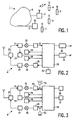
- Fig. 1 schematically shows a cordless telecommunications system 1 comprising primary radio stations 2 and 3, and secondary radio stations 4, 5, 6 and 7.
- the radio stations 2, 4, 5 and 6 are matched to each other in that they all have the same identification code. These stations form a so-called multi-handset cordless telephone according to the CT0 Standard or the CT1 Standard, for instance.
- the stations 3 and 7 are also matched to each other.
- the primary stations 2 and 3 are coupled to the public switched telephone network 8.
- the shown devices are suitable for at least telephony speech traffic.
- Fig. 2 shows a block diagram of the primary station 2 according to the present invention.
- the station 2 comprises a reception path and a transmission path coupled to an antenna switch 20.
- the reception path comprises a cascade of a tuneable RF-filter 21, a mixer 22, a demodulator/decoder 23.
- the mixer 22 is further coupled to tuneable frequency generation means 24 so that the receiver can be tuned to a given channel.
- the transmission path comprises a cascade of the coder/modulator 25, a mixer 26, and a power amplifier 27.
- the mixer 26 is further coupled to tuneable frequency generating means 28.
- a micro controller 29 having a programmed ROM (Read Only Memory) and/or a programmed EEPROM (Electrically Alterable Programmable Read Only Memory) and a RAM (Random Access Memory) is provided for controlling the functionality of the primary station 2.
- the micro controller 29 is further coupled to a power supply 30 and to a line interface circuit 31 for coupling the primary station 2 to the public switched telephone network 8.
- Conventional functionality such as controlling the frequency generating means 24 and 28 so as to tune to a specific frequency channel and scanning an (optional) keypad 32, is not described in further detail here, such functioning being well-known in the art.
- the primary station 2 comprises an RSSI detector (Received Signal Strength Indicator) 33 coupled between the RF-filter 21 and the micro controller 29 for measuring the field strength of the received signal in the channel to which the primary station is tuned.
- RSSI detector Receiveived Signal Strength Indicator
- Fig. 3 shows a block diagram of the secondary station 4 according to the present invention.
- the station 4 comprises a reception path and a transmission path coupled to an antenna switch 40.
- the reception path comprises a cascade of a tuneable RF-filter 41, a mixer 42, a demodulator/decoder 43.
- the mixer 42 is further coupled to tuneable frequency generation means 44 so that the receiver can be tuned to a given channel.
- the transmission path comprises a cascade of the coder/modulator 45, a mixer 46, and a power amplifier 47.
- the mixer 46 is further coupled to tuneable frequency generating means 48.
- the micro controller 49 is further coupled to a keypad 50 and to a display 51.
- the demodulator/decoder 43 is coupled to a speaker 52 in the receive path and to the micro controller 49.
- the coder/modulator 45 is coupled to a microphone 53 in the transmit path.
- Conventional functionality such as controlling the frequency generating means 44 and 48 so as to tune to a specific frequency channel and scanning the keypad 50, is not described in further detail here, such functioning being well-known in the art.
- voice signals are transmitted over the air interface as FM (Frequency Modulated) signals modulated on a carrier
- messages to be transmitted over the air interface are Manchester coded binary messages which can be evaluated by the micro controllers 29 and 49, after demodulation and decoding.
- Manchester coded messages and FM are well-known in the art.
- the programmed micro controllers 29 and 49 contain suitable parts of the programs for implementing the protocols according to the present invention.
- the secondary station 4 comprises an RSSI detector (Received Signal Strength Indicator) 54 coupled between the RF-filter 41 and the micro controller 49 for measuring the field strength of the received signal in the channel to which the secondary station is tuned.
- RSSI detector Receiveived Signal Strength Indicator
- Fig. 4 shows a state diagram 60 for illustrating the operation of the programs according to the present invention.
- the programs are a set of real time software processes which are event driven, i.e., if a particular event occurs, such as an event 61, a transition occurs from a process state 62 to another process state 63 after an action 64 has been carried out. Events can also cause a jump to a state of another process.
- event driven i.e., if a particular event occurs, such as an event 61, a transition occurs from a process state 62 to another process state 63 after an action 64 has been carried out. Events can also cause a jump to a state of another process.
- Such an organisation of software in the form of finite state machines is well-known in the art.
- Fig. 5 shows processes to implement the protocols according to the present invention.
- Processes can send events to another process. Shown are a layer-1 CODEC process CDC, a layer-2 FRAME process FRM, a layer-3 Radio Link Control process RLC, a higher layer Supervisor process SUP, and a layer-1+ process RSSI.
- Arrows indicate software channels for exchanging events between processes. Such a layer structure of software and exchanging of events is well-known per se.
- Layer-1 is usually called the physical layer via which signals are conveyed from the primary station 2 to the secondary station 4, and vice versa.
- At layer-2 Frames of messages are built, at layer-3 radio link control is done, and at the higher layers higher level software is run at a supervisor-level.
- the operation of the protocols according to the present invention will be described in terms of event driven software processes and the timing thereof.
- Fig. 6 shows a message format MSG for the above events.
- the message MSG is a variable length message comprising the following message fields, a 16 bits Start field STA, a 5 bits Frame Length field FL, a 1 bit Scramble-bit field SC, a 2 bits Stream Bits field SB, an 8 bits Mobile Number field MN, an 8 bits Checksum field CS, a 16 bits Identification Code field IC, an 8 bits Radio Link Data field RLD, and an N*8 bits Application User Data field USD.
- the field STA contains a Manchester code word for synchronisation which is different for the primary station 2 and the secondary station 4 so as to avoid self-reception of frames.
- the two bits SB change with each transmission of the same message.
- the Mobile Number MN is used with point to point radio links.
- handsets in a multi-handset cordless phone can be distinguished.
- the Identification Code is put in each frame.
- the user data contain information belonging to a particular radio link.
- the user data field USD is of variable length N, N being an integer value varying from 0 to a given positive value.
- Fig. 7 shows a signalling diagram for the double checking protocol according to the present invention. Shown are a calling station CALLER and a called station CALLED. The CALLER and the CALLED can be a primary station and a secondary station, and vice versa. A point to point radio link is set up. Shown are events between the software processes as described as a function of time. Time evolves from the top of the diagram to the bottom of the diagram. At the level of the Supervisor SUP, so-called Primitives are generated initiating basic processes. In Fig. 7, the Primitive Est_Req is generated, initiating call establishment. The RSSI process is not indicated separately but is still present, this being indicated with dashed arrows.
- this handset first carries out a complete channel scanning cycle so as to check whether the base station has not already initiated a call establishment protocol.
- the CALLER checks for a free channel by evaluating its RSSI signal, a free channel being indicated to the process RLC of the CALLER in 71. Then, the CALLER switches on its transmitter, indicated with TxCRON so that the CALLED detects a busy channel occupied by the CALLER, indicated with 72 and 73. Thereafter, the CALLER's process RLC issues an event Bld(Act) to its process FRM for building up an Activation message Act.
- the activation message Act is assembled in a message format as described in Fig.
- the CALLER's process FRM issues an event Tx(Act, UCR) to its layer-1 Codec process CDC.
- activation messages are sent to the Codec process of the CALLED via the air interface in an Unlimited Continuous Repetition mode UCR. This is indicated with connected arrows Tx(Act).
- the CALLED receives the activation message Rx(Act) and the CALLED's frame process FRM disassembles the received frame and informs its radio link control process RLC that it has received an activation message Act by issuing an event Fr_ind(Act).
- the CALLED switches on its transmitter, indicated with TxCDON so that the CALLER's process RSSI detects a CALLED's busy channel, indicated with 74. It is essential that the CALLER now switches off its transmitter, indicated with TxCROF so that the CALLED sees a free channel. After the CALLER has switched off its transmitter, the CALLED should see the corresponding channel free for a period of time t CF . This is because in the meantime another caller could have seized the free channel.
- the CALLED should see the channel free for the whole period t 2 , from the instant it had switched on its transmitter until the end of the period t CF , but because of the fact that the CALLER should first switch off its transmitter, the actual scanning period is t CF .
- Channel free is indicated with the connected dashed arrows 75 and 76.
- the CALLED builds an activation acknowledgement frame at an event Bld(Act_Ack) and transmits an activation acknowledge message to the CALLER at an event Tx(Act_Ack) via the air interface in a Limited Continuous Repetition mode LCR, i.e., the acknowledgement message is transmitted a given number of times, indicated with the connected arrows Tx(Ack).
- the CALLER's process CDC issues an event Rx(Ack) to its frame disassembling process FRM, which process issues an event Fr_Ind(Ack) to its radio link control process RLC, which process issues an event Est_Ind to its supervisor SUP.
- the point to point radio link is established and the CALLER switches on its transmitter, indicated with TxCRON.
- the CALLER transmits user data to the caller, initiating of transmission being indicated with the Primitive UD_Req and reception at supervisor level being indicated with UD_Ind.
- the Primitive UD_Req will be described in Fig. 8.
- time outs are applied when waiting for a response of the other party.
- the supervisor should be informed that the link is established by receiving the event Est_Ind.
- time outs t 1 and t 3 are defined for the CALLER's radio link control process RLC, and a time out t 4 for the CALLED's radio link process RLC.
- the entity adopts a channel scanning mode again.
- Fig. 8 shows a signalling diagram for transmission of user data in a double checking protocol according to the present invention.
- User defined messages are transmitted via an already established radio link.
- the CALLER's supervisor issues an event UD_Req to its radio link process RLC, which process issues a frame building event Bld(UD_Msg) to its frame process FRM, which process issues a transmit user defined message to its codec CDC.
- the contents of the user defined message UD_Msg depends on the application thereof.
- the user defined message is used for radio link confirmation.
- the user defined message is transmitted a number of times, in the given example three times, at regular intervals T r . If after the third transmission no acknowledgement is received, the CALLER will release the radio link before returning to idle mode.
- Reception of the user defined message is indicated by the events Rx(UD_Msg), Fr_Ind(UD_Msg), and UD_Ind. Transmission and reception of an acknowledgement message is indicated by the events Tx(Ack) and Rx(Ack).
Abstract
Description
Claims (9)
- A channel selection protocol for use in a telecommunications system (1) comprising at least one primary radio station (2) and a plurality of secondary radio stations (4, 5, 6), in which system a secondary radio station is matched to a primary radio station and a wireless communication between matched radio stations is done via a full duplex communication link, and the primary and the secondary stations are arranged for establishing the communication link to their respective opposite station while scanning for a free communication channel, whereby the stations have a transmitter and a receiver,
characterised in that the station establishing the communication link issues an establishment request for establishing the communication link with the opposite station while applying a double checking protocol for checking whether both channels in the duplex communication link are free, which double checking protocol comprises the following steps:a) after having found a free channel (70), the establishing station switches on its transmitter (72) and transmits at least one activation message to the opposite station,b) after having received and decoded an activation message, the opposite station switches on its transmitter on a free channel and checks for a first predetermined period of time (t2) whether the establishing station has switched off its transmitter within the first period on the channel on which it transmits the at least one activation message,c) the establishing station switches off its transmitter after having found a busy channel of the opposite station (74),d) if is ascertained that after the checking in b) the channel is free, the opposite station transmits at least one acknowledgement message on the channel it has selected after having received the activation message, ande) the establishing station switches on its transmitter on the channel it was transmitting the at least one activation message after having received and decoded the acknowledgement message. - A telecommunications system (1) comprising at least one primary radio station (2) and a plurality of secondary radio stations (4, 5, 6), in which system a secondary radio station is matched to a primary radio station and a wireless communication between matched radio stations is done via a full duplex communication link, and the primary and the secondary stations are arranged for establishing the communication link to their respective opposite station while scanning for a free communication channel, whereby the stations have a transmitter and a receiver,
characterised in that the station establishing the communication link is arranged for issuing an establishment request for establishing the communication link with the opposite station while applying a double checking protocol as claimed in claim 1, for checking whether both channels in the duplex communication link are free. - A telecommunications system (1) according to claim 2, wherein the establishing station is arranged to check whether after a second predetermined period of time (t1) after it has first switched on its transmitter the opposite station has seized a channel for the full duplex communication link.
- A telecommunications system (1) according to any one of the claims 2-3, wherein the establishing station is arranged to check whether after a third predetermined period of time (t3) after having switched off its transmitter the acknowledgement message was received.
- A telecommunications system (1) according to any one of the claims 2-4, wherein the opposite station is arranged to check whether after a fourth predetermined period of time (t4) after having issued an acknowledgement message it has received user data from the establishing station confirming the link establishment and the opposite station is further arranged to enter a channel scanning mode if it has not received such confirmation data.
- A telecommunications system (1) according to any one of the claims 2-5, wherein the establishing station is arranged to transmit the activation message repetitively and continuously.
- A telecommunications system (1) according to any one of the claims 2-6, wherein the opposite station is arranged to transmit the acknowledgement message repetitively for a predetermined number of times.
- A first radio station for use in a telecommunications system (1) comprising at least one primary radio station (2) and a plurality of secondary radio stations (4, 5, 6), in which system a secondary radio station is matched to a primary radio station and a wireless communication between matched radio stations is done via a full duplex communication link, and the primary and the secondary stations are arranged for establishing the communication link to their respective opposite station while scanning for a free communication channel, whereby the stations have a transmitter and a receiver,
characterised in that the first radio station is arranged for establishing the communication link by issuing an establishment request for establishing the communication link with a second station while applying a double checking protocol for checking whether both channels in the duplex communication link are free, with the first radio station being arranged to:a) after having found a free channel (70), switch on its transmitter (72) and transmit at least one activation message to the second station,b) switch off its transmitter after having found a busy channel of the second station (74), which channel was seized by the second station after having received and decoded an activation message, after which the second station had switched on its transmitter on a free channel and had initiated checking for a first predetermined period of time (t2) whether the first station had switched off its transmitter within the first period on the channel on which it had transmitted the at least one activation message, andc) switch on its transmitter on the channel it was transmitting the at least one activation message after having received and decoded an acknowledgement message received from the second station on the channel it had selected after having received the activation message. - A second radio station for use in a telecommunications system (1) comprising at least one primary radio station (2) and a plurality of secondary radio stations (4, 5, 6), in which system a secondary radio station is matched to a primary radio station and a wireless communication between matched radio stations is done via a full duplex communication link, and the primary and the secondary stations are arranged for establishing the communication link to their respective opposite station while scanning for a free communication channel, whereby the stations have a transmitter and a receiver,
characterised in that the second radio station is arranged for evaluating an establishment request for establishing the communication link received from a first station issuing an establishment request for establishing the communication link with the second opposite station while applying a double checking protocol for checking whether both channels in the duplex communication link are free, with the second radio system being arranged to:a) after having received and decoded an activation message, which was transmitted by the first station after having found a free channel (70) and having switched on its transmitter (72), switch on its transmitter on a free channel and check for a first predetermined period of time (t2) whether the first station has switched off its transmitter within the first period on the channel on which it transmits the at least one activation message,b) transmit at least one acknowledgement message on the channel it has selected after having received the activation message when it had found that the first station had switched off its transmitter.
Priority Applications (1)
| Application Number | Priority Date | Filing Date | Title |
|---|---|---|---|
| EP97943098A EP0882348B1 (en) | 1996-11-29 | 1997-10-20 | A telecommunications system, a channel selection protocol, and a radio station |
Applications Claiming Priority (4)
| Application Number | Priority Date | Filing Date | Title |
|---|---|---|---|
| EP96402585 | 1996-11-29 | ||
| EP96402585 | 1996-11-29 | ||
| PCT/IB1997/001293 WO1998024217A1 (en) | 1996-11-29 | 1997-10-20 | A telecommunications system, a channel selection protocol, and a radio station |
| EP97943098A EP0882348B1 (en) | 1996-11-29 | 1997-10-20 | A telecommunications system, a channel selection protocol, and a radio station |
Publications (2)
| Publication Number | Publication Date |
|---|---|
| EP0882348A1 EP0882348A1 (en) | 1998-12-09 |
| EP0882348B1 true EP0882348B1 (en) | 2005-02-09 |
Family
ID=8225326
Family Applications (1)
| Application Number | Title | Priority Date | Filing Date |
|---|---|---|---|
| EP97943098A Expired - Lifetime EP0882348B1 (en) | 1996-11-29 | 1997-10-20 | A telecommunications system, a channel selection protocol, and a radio station |
Country Status (7)
| Country | Link |
|---|---|
| US (1) | US6061569A (en) |
| EP (1) | EP0882348B1 (en) |
| JP (1) | JP2000504532A (en) |
| KR (1) | KR19990082058A (en) |
| CN (1) | CN1179534C (en) |
| DE (1) | DE69732481D1 (en) |
| WO (1) | WO1998024217A1 (en) |
Cited By (1)
| Publication number | Priority date | Publication date | Assignee | Title |
|---|---|---|---|---|
| CN101425941B (en) * | 2008-12-04 | 2010-09-29 | 北京星网锐捷网络技术有限公司 | Loop network link convergence time and recovery time test system |
Families Citing this family (6)
| Publication number | Priority date | Publication date | Assignee | Title |
|---|---|---|---|---|
| US6252859B1 (en) * | 1997-06-16 | 2001-06-26 | Racal Communications Systems Limited | Radio communications system |
| ATE288640T1 (en) * | 1999-10-11 | 2005-02-15 | Nokia Corp | METHOD AND DEVICE FOR SYNCHRONIZATION IN A COMMUNICATIONS SYSTEM |
| US6463285B1 (en) * | 2000-02-09 | 2002-10-08 | Lucent Technologies Inc. | Arrangement for data exchange in a wireless communication system |
| TW536871B (en) * | 2002-01-31 | 2003-06-11 | Elan Microelectronics Corp | Wireless communication coding method for representing digital data with variable length signal |
| US7251488B2 (en) | 2002-06-28 | 2007-07-31 | Interdigital Technology Corporation | Method and system for coordinating services in integrated WLAN-cellular systems |
| US10512017B2 (en) * | 2017-05-16 | 2019-12-17 | II John Thomas Walker | Device for radio communications and method for establishing and maintaining communications between device and fixed location radio communication facilities |
Family Cites Families (7)
| Publication number | Priority date | Publication date | Assignee | Title |
|---|---|---|---|---|
| JPH0815347B2 (en) * | 1985-08-27 | 1996-02-14 | 日本電信電話株式会社 | Wireless telephone system |
| JP2642380B2 (en) * | 1988-02-16 | 1997-08-20 | 日本電信電話株式会社 | Wireless communication device |
| JP2595758B2 (en) * | 1990-04-24 | 1997-04-02 | 日本電気株式会社 | Cordless telephone system |
| JP2954389B2 (en) * | 1991-06-06 | 1999-09-27 | パイオニアコミュニケーションズ株式会社 | Cordless telephone transfer unit between handset units |
| US5644621A (en) * | 1994-01-11 | 1997-07-01 | Matsushita Electric Industrial Co., Ltd. | Point to multipoint radiotelephone system |
| FI105001B (en) * | 1995-06-30 | 2000-05-15 | Nokia Mobile Phones Ltd | Method for Determining Wait Time in Speech Decoder in Continuous Transmission and Speech Decoder and Transceiver |
| JP2959462B2 (en) * | 1996-01-19 | 1999-10-06 | 日本電気株式会社 | Communication channel setting method |
-
1997
- 1997-10-20 EP EP97943098A patent/EP0882348B1/en not_active Expired - Lifetime
- 1997-10-20 DE DE69732481T patent/DE69732481D1/en not_active Expired - Lifetime
- 1997-10-20 WO PCT/IB1997/001293 patent/WO1998024217A1/en not_active Application Discontinuation
- 1997-10-20 JP JP10524455A patent/JP2000504532A/en not_active Withdrawn
- 1997-10-20 KR KR1019980705779A patent/KR19990082058A/en not_active Application Discontinuation
- 1997-10-20 CN CNB971919143A patent/CN1179534C/en not_active Expired - Fee Related
- 1997-11-24 US US08/976,647 patent/US6061569A/en not_active Expired - Fee Related
Cited By (1)
| Publication number | Priority date | Publication date | Assignee | Title |
|---|---|---|---|---|
| CN101425941B (en) * | 2008-12-04 | 2010-09-29 | 北京星网锐捷网络技术有限公司 | Loop network link convergence time and recovery time test system |
Also Published As
| Publication number | Publication date |
|---|---|
| EP0882348A1 (en) | 1998-12-09 |
| CN1179534C (en) | 2004-12-08 |
| DE69732481D1 (en) | 2005-03-17 |
| JP2000504532A (en) | 2000-04-11 |
| WO1998024217A1 (en) | 1998-06-04 |
| KR19990082058A (en) | 1999-11-15 |
| CN1209926A (en) | 1999-03-03 |
| US6061569A (en) | 2000-05-09 |
Similar Documents
| Publication | Publication Date | Title |
|---|---|---|
| EP0213929B1 (en) | Radio telephone system control apparatus and method | |
| EP0167331B1 (en) | Signal transmission apparatus | |
| AU715234B2 (en) | Checking the presence of mobile stations communicating on a direct mode channel | |
| EP0248351B1 (en) | Cordless telephone system | |
| US4897864A (en) | Control method and appartus for a radio telephone system | |
| US5140628A (en) | Radio telephone system control method | |
| CA2254403A1 (en) | Mobile communication termination controlling method and mobile communication termination controlling system | |
| AU608334B2 (en) | Radio communication system | |
| EP0454080B1 (en) | Cordless telephone system capable of quickly establishing connection during call setup phase | |
| EP0882348B1 (en) | A telecommunications system, a channel selection protocol, and a radio station | |
| US6549783B1 (en) | Telecommunications system, a channel extension protocol, and a radio station | |
| JP3870761B2 (en) | Wireless telephone equipment | |
| EP0363492B1 (en) | Radio communication system and its control method | |
| KR20010081627A (en) | Method for Data Transmission and Reception when Voice Communication in Mobile Telecommunication Terminal | |
| JPH02241235A (en) | Radio telephone system | |
| KR920009152B1 (en) | Local area radio telephone system | |
| JP3169860B2 (en) | Mobile communication system and communication range determination method thereof | |
| JPS6248137A (en) | Radiotelephoney system | |
| JPS62204631A (en) | Incoming call in absence detection system | |
| JP3055478B2 (en) | Wireless telephone equipment | |
| JP2936602B2 (en) | Cordless telephone equipment | |
| JP3017975B2 (en) | Wireless communication device | |
| JPH0748899B2 (en) | Wireless communication device | |
| JPH11146448A (en) | Portable telephone communication method and system | |
| JPH0548531A (en) | Idle channel search system in cordless telephone set |
Legal Events
| Date | Code | Title | Description |
|---|---|---|---|
| PUAI | Public reference made under article 153(3) epc to a published international application that has entered the european phase |
Free format text: ORIGINAL CODE: 0009012 |
|
| AK | Designated contracting states |
Kind code of ref document: A1 Designated state(s): DE ES FR GB IT |
|
| 17P | Request for examination filed |
Effective date: 19981204 |
|
| 17Q | First examination report despatched |
Effective date: 20031029 |
|
| GRAP | Despatch of communication of intention to grant a patent |
Free format text: ORIGINAL CODE: EPIDOSNIGR1 |
|
| GRAS | Grant fee paid |
Free format text: ORIGINAL CODE: EPIDOSNIGR3 |
|
| GRAA | (expected) grant |
Free format text: ORIGINAL CODE: 0009210 |
|
| AK | Designated contracting states |
Kind code of ref document: B1 Designated state(s): DE ES FR GB IT |
|
| PG25 | Lapsed in a contracting state [announced via postgrant information from national office to epo] |
Ref country code: IT Free format text: LAPSE BECAUSE OF FAILURE TO SUBMIT A TRANSLATION OF THE DESCRIPTION OR TO PAY THE FEE WITHIN THE PRESCRIBED TIME-LIMIT;WARNING: LAPSES OF ITALIAN PATENTS WITH EFFECTIVE DATE BEFORE 2007 MAY HAVE OCCURRED AT ANY TIME BEFORE 2007. THE CORRECT EFFECTIVE DATE MAY BE DIFFERENT FROM THE ONE RECORDED. Effective date: 20050209 Ref country code: FR Free format text: LAPSE BECAUSE OF NON-PAYMENT OF DUE FEES Effective date: 20050209 |
|
| REG | Reference to a national code |
Ref country code: GB Ref legal event code: FG4D |
|
| REF | Corresponds to: |
Ref document number: 69732481 Country of ref document: DE Date of ref document: 20050317 Kind code of ref document: P |
|
| PG25 | Lapsed in a contracting state [announced via postgrant information from national office to epo] |
Ref country code: DE Free format text: LAPSE BECAUSE OF FAILURE TO SUBMIT A TRANSLATION OF THE DESCRIPTION OR TO PAY THE FEE WITHIN THE PRESCRIBED TIME-LIMIT Effective date: 20050510 |
|
| PG25 | Lapsed in a contracting state [announced via postgrant information from national office to epo] |
Ref country code: ES Free format text: LAPSE BECAUSE OF FAILURE TO SUBMIT A TRANSLATION OF THE DESCRIPTION OR TO PAY THE FEE WITHIN THE PRESCRIBED TIME-LIMIT Effective date: 20050520 |
|
| PG25 | Lapsed in a contracting state [announced via postgrant information from national office to epo] |
Ref country code: GB Free format text: LAPSE BECAUSE OF NON-PAYMENT OF DUE FEES Effective date: 20051020 |
|
| PLBE | No opposition filed within time limit |
Free format text: ORIGINAL CODE: 0009261 |
|
| STAA | Information on the status of an ep patent application or granted ep patent |
Free format text: STATUS: NO OPPOSITION FILED WITHIN TIME LIMIT |
|
| 26N | No opposition filed |
Effective date: 20051110 |
|
| EN | Fr: translation not filed | ||
| GBPC | Gb: european patent ceased through non-payment of renewal fee |
Effective date: 20051020 |