BACKGROUND OF THE INVENTION
1. FIELD OF THE INVENTION
The present invention relates to mobile communications
equipment. More particularly, it relates to mobile
communications equipment which is well suited to a case
where a communications terminal moves out of a service area
or to a case where it is connectible to a plurality of
sorts of network.
2. DESCRIPTION OF THE RELATED ART
In mobile communications, a radio channel for
communication is established between a mobile
communications terminal which moves on the ground, on the
sea or in the sky and a base station or relay station which
is fixed, e. g., on the ground or a satellite which is
revolving round the earth. Whenever the base station or
the like is located within a range in which a radio signal
is reachable, the mobile communications terminal can be
connected with the channel for both call origination and
call termination. In a case where the mobile
communications terminal is moving within such a service
area, the user thereof need not especially worry about
being able to talk. Since, however, base stations are not
installed in all areas, the mobile communications terminal
might move out of the service area. When the mobile
terminal has moved out of the service area in this manner,
a display is commonly presented on a display unit or the
like to indicate that the mobile terminal currently lies in
an area where communication is impossible.
With the conventional mobile communications terminal
as stated above, unless the user looks at the display,
he/she cannot judge whether or not the terminal is
currently in the service area. In a case where the user
wants to communicate while walking or while moving aboard
an automobile or streetcar by way of example, he/she first
checks the display of the mobile communications terminal.
When the display indicates "outside the service area", the
user abandons the desired communication. Thereafter,
he/she needs to look at the display unit again and again in
order to check if the terminal has entered the service area
in which communication is possible. This is rather
troublesome for the user. Especially when driving the
automobile, the operation of checking the display can
hamper the driving movement and is a serious hazard to
safety.
Besides, in the case of a personal telephone set whose
communicable range is as narrow as 10 [meters] ∼ several
hundred [meters], it is quite natural that the user will
pass the service area without noticing his/her entry
even when he/she is walking.
Techniques intended to solve the above drawbacks are
disclosed in the official gazettes of Japanese Patent
Applications Laid-open No. 318326/1989, No. 250727/1992,
No. 314442/1989 and No. 207724/1992. With each of the
techniques stated in the official gazettes of Japanese
Patent Applications Laid-open No. 318326/1989 and No.
314442/1989, the first audible sound is generated when it
is decided that a mobile communications equipment is lying
inside the service area of a base station on the basis of a
signal transmitted from the base station, and the second
audible sound is generated when it is decided that the
equipment is lying outside the service area. Thus, the
user of the mobile communications equipment can be reliably
informed as to whether or not the equipment lies within the
service area. In addition, the technique stated in the
official gazette of Japanese Patent Application Laid-open
No. 250727/1992 consists in comprising a reception means
for detecting a communicable state through a base station,
and transfer means adapted to turn "on" in accordance with
a communicability signal detected by the reception means,
for transferring the communicable state in terms of
notification expedients such as a sound, a display and
vibrations. It is claimed that, in this way, the presence
of the base station can be automatically made known through
the use of the five senses in a car or on the street.
Further, with the technique stated in the official gazette
of Japanese Patent Application Laid-open No. 207724/1992,
the reception levels of a plurality of sorts of signals
from a transmitter are detected for deciding the quality of
a reception state, the duration for which the reception
state is decided to be no good is compared with a preset
time period, and an output signal is produced when the
duration has exceeded the preset time period.
With any of the prior-art techniques, the user is
notified that the mobile communications equipment has
fallen into the communicable state. In this regard, even
when not necessary, the notification is given whenever the
communicable state has been established. That is, even
when the user does not want to originate a call with the
mobile communications equipment, he/she is notified.
Accordingly, in the case where the notifying sound (beep)
is used by way of example, it is useless information and is
noisy.
Furthermore, increase in network offerers is expected
owing to the progress of communications networks in the
future. In this case, service contents, charges for
communications, etc. might become different depending upon
the offerers of network, and users will select the sorts of
the networks. Nevertheless, the prior art has not provided
any convenient means for selecting one of the networks and
for deciding whether or not the selected network is
communicable.
SUMMARY OF THE INVENTION
The present invention has been made in order to solve
the problems explained above, and has for its object to
provide a mobile communications equipment which can detect
the change of a state based on the movement thereof, such
as the change from outside a service area into the service
area, and which permits the user thereof to designate
whether or not he/she is to be notified of the state
change.
In the present invention, a mobile communications
equipment for communicating with another equipment through
a base station can comprise a radio-frequency signal
circuit which receives a signal sent from the base station,
and which transmits a signal directed back toward the base
station; a demodulation circuit which demodulates the
signal received by the radio-frequency signal circuit;
input/output means for delivering the signal demodulated by
the demodulation circuit, to a mobile communications
equipment user, and for accepting an input signal to-be-transmitted
from the user; a modulation circuit which
modulates the signal accepted by the input/output means,
and which delivers the modulated signal to the radio-frequency
signal circuit; analysis means for analyzing
whether or not the communications are possible, on the
basis of the received signal of the radio-frequency signal
circuit sent from the base station; detection means for
detecting a change between a state in which the equipment
is communicable and a state in which it is incommunicable,
in accordance with an output of the analysis means;
notification means for notifying the user of the state
change when the state change has been detected by the
detection means; an instruction input unit which accepts an
instruction as to whether or not the notification is to be
given by the notification means in response to the state
change detection of the detection means; and control means
for controlling the notification means so as to inhibit the
notification in a case where the instruction accepted by
the instruction input unit indicates that notification is
not to be given.
It is allowed that the notification means includes at
least two constituent means selected from the group
consisting of message output means for producing a voice
message as the notification; sound output means for
producing a notifying sound as the notification; optical
indication means for producing a notifying light as the
notification; and vibration means for producing vibrations
as the notification. In this case, the control means can
select different constituent means of the notification
means for the detected state change from the incommunicable
state into the communicable state to that used for the
change from the communicable state into the incommunicable
state.
The instruction input unit can further accept an
instruction for selecting which of the at least two
constituent means of the notification means is to be used
for the notification; and the control means can select any
of the constituent means of the notification means in
accordance with the selection instruction accepted by the
instruction input unit. The message output means, the sound
output means, the optical indication means, and the
vibration means can produce at least two sorts of voice
messages, at least two sorts of notifying sounds, at least
two sorts of notifying lights, and at least two sorts of
vibrations, respectively; the instruction input unit can
further accept instructions for selecting which of the at
least two constituent means of the notification means and
which of the sorts of the outputs to-be-produced are to be
used for the notification; and the control means can select
any of the constituent means of the notification means and
any of the sorts of the outputs in accordance with the
selection instructions accepted by the instruction input
unit or the control means can select the different sorts of
the outputs to-be-produced of the constituent means of the
notification means between at the detected state change of
the detection means from the incommunicable state into the
communicable state and at the change thereof from the
communicable state into the incommunicable state.
It is possible that, when the notification of the
notification means is to be given, the instruction input
unit further accepts an instruction for selecting either of
giving the notification in response to every state change
and giving the notification in response to only the first
state change after the selection instruction; and that the
control means controls the notification means in accordance
with the selection instruction accepted by the instruction
input unit.
Further, the mobile communications equipment can
further comprise timekeeping means for detecting the fact
that no state change has taken place for a predetermined
time period since the last state change; the control means
deciding settlement of the last state change in accordance
with the detection of the timekeeping means and then
controlling the notification means so as to give
notification. In this case, it is possible that the
instruction input unit can further accept an instruction
for selecting as a condition for giving the notification,
either of the state change detection of the detection means
and the detected fact of the timekeeping means; and that
the control means controls the notification means in
accordance with the selection instruction accepted by the
instruction input unit.
In addition, the mobile communications equipment can
further comprise electric field strength detection means
for detecting a received electric field strength of the
signal received by the radio-frequency signal circuit; the
control means deciding settlement of the communicable state
and controlling the notification means so as to give the
notification in a case where the change into the
communicable state as based on the analysis of the analysis
means has been detected by the detection means and where
the detected electric field strength of the electric field
strength detection means has reached a predetermined
electric field strength. In this case, it is possible that
the instruction input unit can further accept an
instruction for selecting either of the specified situation
and the state change detection of the detection means as a
condition for giving the notification; and that the control
means controls the notification means in accordance with
the selection instruction accepted by the instruction input
unit.
The detection means is allowed to detect only the
state change from the incommunicable state into the
communicable state as based on the analysis of the analysis
means. Alternatively, the detection means can detect both
the state change from the incommunicable state into the
communicable state as based on the analysis of the analysis
means and the state change from the communicable state into
said incommunicable state.
Besides, the instruction input unit can accept
identification information of the other equipment, and the
mobile communications equipment can further comprise a
memory which stores therein the identification information
accepted by the instruction input unit; a starter which
starts commencement of the communications in accordance
with the stored identification information of the memory;
and a checker which is furnished with an autodialing mode
for commanding the starter to start the communications
commencement in response to the change from the
incommunicable state into the communicable state as
detected by the detection means, in a case where an
instruction for the communications commencement has been
accepted in the incommunicable state by the instruction
input unit.
In addition, the checker may well include means for
selectively enabling the autodialing mode.
It is also possible that the notification means is
furnished with at least two sorts of output aspects; the
instruction input unit further accepts an instruction for
selecting which of the output aspects is to be used for the
notification; and the control means selects any of the
output aspects in accordance with the selection instruction
accepted by the instruction input unit, or the control
means selects the different output aspects between at the
detected state change of the detection means from the
incommunicable state into the communicable state and at the
change thereof from the communicable state into the
incommunicable state.
Moreover, in the presence of a plurality of sorts of
network, it is possible that the mobile communications
equipment further comprises network registration means for
registering available sorts of network; that the analysis
means further decides that any of the sorts of network are
communicable on the basis of the signal received by the
radio-frequency signal circuit; that the detection means
detects the state change of the decided sort of
communicable network on the basis of the analyzed result of
the analysis means; and that the notification means gives
notification when the state change of the decided sort of
communicable network has been detected by the detection
means. In this case, the equipment is also allowed to
further comprise network priority setting means for setting
priority levels for the sorts of network, and for selecting
any of the networks in accordance with the set priority
levels. Besides, the notification means can be furnished
with at least two sorts of output aspects; and the control
means stipulates the different output aspects for the
respective sorts of the networks beforehand, and selects
any of the output aspects corresponding to the sort of the
network having undergone the state change. The
notification means includes at least two constituent means
selected from the group consisting of message output means
for producing a voice message as the notification; sound
output means for producing a notifying sound as the
notification; optical indication means for producing a
notifying light as the notification; and vibration means
for producing vibrations as the notification; and the
control means stipulates the different constituent means of
the notification means for the respective sorts of the
networks beforehand, and selects any of the constituent
means corresponding to the sort of the network having
undergone the state change. Further, when each of the
multiple notification means have at least more than two
sorts of constituent means, the control means stipulates
the sorts of the outputs to-be-produced of the constituent
means of the notification means for the respective sorts of
the networks beforehand, and selects any of the sorts of
the outputs of the constituent means corresponding to the
sort of network having undergone the state change.
As an alternative aspect of performance, the mobile
communications equipment further comprises network
registration means for registering available sorts of
network; the analysis means further analyzing the networks
being communicable on the basis of the signal received by
the radio-frequency signal circuit, with reference to the
network registration means; the detection means detecting
the state change of each of the communicable networks on
the basis of the analyzed result of the analysis means; the
notification means giving notification when the state
change of each communicable network has been detected by
the detection means. In this case, the notification means
can include at least two constituent means selected from
the group consisting of message output means for producing
a voice message as said notification; sound output means
for producing a notifying sound as the notification;
optical indication means for producing a notifying light as
the notification; and vibration means for producing
vibrations as the notification; and the control means
stipulates the different constituent means of the
notification means beforehand for the detected state change
of the detection means from the incommunicable state into
the communicable state, the change thereof from the
communicable state into the incommunicable state, and the
sorts of network, respectively, and selects any of the
constituent means corresponding to the detected state
change and the sort of network having undergone the state
change. Further, when each of the multiple notification
means have at least more than two sorts of constituent
means, the control means stipulates the constituent means
of the notification means and the sorts of the outputs to-be-produced
of the constituent means beforehand for the
detected state change of the detection means from the
incommunicable state into the communicable state, the
change thereof from the communicable state into the
incommunicable state, and the sorts of network,
respectively, and selects any of the sorts of said outputs
of the constituent means corresponding to the detected
state change and the sort of network having undergone the
state change. Instead of stipulating the sort of outputs
to-be-produced of the notification means, in accordance with
the sort of outputs to-be-produced the instruction input
unit can further accept instructions for selecting which of
the constituent means of the notification means and which
of the sorts of the outputs to-be-produced are to be used
for the notification in accordance with the detected state
change of the detection means from the incommunicable state
into the communicable state, the change thereof from the
communicable state into the incommunicable state, and the
sorts of network, respectively; and the control means
selects any of the constituent means of the notification
means and any of the sorts of the outputs corresponding to
the detected state change and the sort of network having
undergone the state change, in accordance with the
selection instructions accepted by said instruction input
unit.
Also in this case, the equipment can further comprise
network priority setting means for setting priority levels
for the sorts of network, and for selecting any network of
higher priority level; the detection means detecting the
state change of the network selected by the network
priority setting means, on the basis of the analyzed result
of the analysis means; the notification means notifying the
user of the detected result of the detection means.
The constructions as described above can provide
mobile communications terminals which are more convenient.
Meanwhile, a method for notification in a mobile
communications equipment which communicates with another
equipment through a base station can comprise the steps of
accepting an instruction as to whether or not a user of the
mobile communications equipment is to be notified that a
state change has occurred between a state in which the
equipment is communicable and a state in which it is
incommunicable; analyzing if the communications are
possible, on the basis of a signal sent from the base
station, subject to the instruction of giving the
notification; detecting the state change from the
incommunicable state into the communicable state on the
basis of the analyzed result; and notifying the user of the
occurrence of the state change into the communicable state
in response to the detection of the state change, by at
least one notifying expedient selected from the group
consisting of production of a voice message, that of a
notifying sound, that of a notifying light, and that of
vibrations. Besides, a network selecting method in the
presence of a plurality of available networks can comprise
the steps of registering sorts of predetermined network
beforehand; setting predetermined priority levels for the
sorts of network; analyzing if the networks are
communicable; detecting that the network of higher priority
level has changed from an incommunicable state into a
communicable state; and giving the notification in response
to the detection of the state change.
Further, a mobile communications equipment for
communicating with another equipment through a base station
may comprise a radio-frequency signal circuit which
receives a signal sent from the base station, and which
transmits a signal directed toward the base station; a
demodulation circuit which demodulates the signal received
by the radio-frequency signal circuit; input/output means
for delivering the signal demodulated by the demodulation
circuit, to a user of the mobile communications equipment,
and for accepting an input signal to-be-transmitted from
the user; a modulation circuit which modulates the signal
accepted by the input/output means, and which delivers the
modulated signal to the radio-frequency signal circuit;
analysis means for analyzing if the communications are
possible, on the basis of the received signal of the radio-frequency
signal circuit sent from the base station;
detection means for detecting a change between a state in
which the equipment is communicable and a state in which it
is incommunicable, in accordance with an output of the
analysis means; and output means for externally delivering
predetermined notifying information when the state change
has been detected by the detection means.
In addition, a mobile communications system can
comprise a mobile communications equipment which
communicates with another equipment through a base station,
and a peripheral equipment which is connected to the mobile
communications equipment; the mobile communications
equipment including a radio-frequency signal circuit which
receives a signal sent from the base station, and which
transmits a signal directed toward the base station; a
demodulation circuit which demodulates the signal received
by the radio-frequency signal circuit; input/output means
for delivering the signal demodulated by the demodulation
circuit, to a user of the mobile communications equipment,
and for accepting an input signal to-be-transmitted from
the user; a modulation circuit which modulates the signal
accepted by the input/output means, and which delivers the
modulated signal to the radio-frequency signal circuit;
analysis means for analyzing if the communications are
possible, on the basis of the received signal of the radio-frequency
signal circuit sent from the base station;
detection means for detecting a change between a state in
which the mobile communications equipment is communicable
and a state in which it is incommunicable, in accordance
with an output of the analysis means; and output means for
delivering predetermined notifying information to the
peripheral equipment when the state change has been
detected by the detection means; the peripheral equipment
including input means for receiving the notifying
information delivered from the output means of the mobile
communications equipment; analysis means for analyzing a
content of the notifying information accepted by the input
means; and notification means for performing a
predetermined notifying operation on the basis of the
analysis of the analysis means.
In this case, the peripheral equipment can further
include an instruction input unit which accepts
identification information of the other mobile
communications equipment; a memory which stores therein the
identification information accepted by the instruction
input unit; a start command unit which commands the mobile
communications equipment to start commencement of the
communications in accordance with the stored identification
information of the memory; and a checker which is furnished
with an autodialing mode for actuating the start command
unit in response to the change from the incommunicable
state into the communicable state as detected by the
detection means, in a case where an instruction for the
communications commencement has been accepted in the
incommunicable state by the instruction input unit.
In operation, the analysis means analyzes the received
signal, and it delivers the output indicative of the
communicable state when the mobile communications terminal
has moved from outside the service area into the service
area. The detection means senses the state change on the
basis of the output of the analysis means. The instruction
input unit accepts the instruction as to whether or not the
notification is to be given by the notification means in
response to the state change. In a case where the
instruction accepted by the instruction input unit appoints
that the notification is not to be given, the control means
controls the notification means so as to inhibit the
notification. Subject to giving the notification, the
notification means responds to the state change in such a
way that the notifying message is given by the message
output means, that the sound is produced by the sound
output means, that the light is flickered by the optical
indication means, or that the vibrations are developed by
the vibration means. Herein, the aspect of notification of
each notification means can be made different between at
the detected state change of the detection means from the
incommunicable state into the communicable state and at the
change from the communicable state into the incommunicable
state, through the control of the control means.
Alternatively, the instruction input unit accepts the
instruction for selecting that (those) constituent means of
the notification means which is (are) to be used for the
notification, whereupon the control means controls the
notification means so as to actuate the selected
constituent means, in conformity with the selection
instruction accepted by the instruction input unit. Thus,
the notification means notifies the user of the
communicability under the control of the control means. In
this way, the user can know the communicability more
conveniently without expressly checking the disappearance
of a display "OUTSIDE SERVICE AREA" on the display unit.
In particular, even when the user is driving an automobile,
he/she can confirm the entry into the service area without
any hindrance to his/her driving movement. This is
effective for safety.
Besides, regarding the terminal which can select any
of a plurality of network services or any of network
offered by a plurality of enterprises, such as an
automobile telephone set, a satellite radiotelephone set or
a cordless telephone set, the notification can be given in
response to the establishment of the communicability of the
desired network or service by setting the priority levels
of the network or services in the network priority setting
means beforehand. Alternatively, the network or service
whose priority level is higher in accordance with the
priority levels of the network or services set in the
priority setting means and which is in the communicable
state may well be selected for notifying the user of the
state change.
Further, when the handled signal has become
unreceivable, the output of the analysis means changes, and
the detection means senses the state change. Then, the
notification means notifies the user of the fact that the
mobile communications equipment has gone out of the service
area. On this occasion, the notification means notifies
the user of the incommunicability in conformity with the
setting in the control means in such a way that the
notifying message is given by the message output means,
that the sound is produced by the sound output means, that
the light is flickered by the optical indication means, or
that the vibrations are developed by the vibration means.
Owing to the above operations, the user can know the
change into the incommunicable or communicable state
without expressly checking the display of the display unit,
only when necessary. Accordingly, the convenience of the
mobile communications equipment is enhanced. Further, the
notification means may well produce the sound at different
intervals or in different tone colors, deliver different
notifying messages or flicker the light in different
aspects, depending upon those outputs of the analysis means
which indicate the communicability, the incommunicability,
the availability of the service of any network set in the
network priority setting means, etc. Thus, the user can
distinguish the situations, and the convenience of the
equipment is enhanced more.
Besides, when the control means is set so as to select
any of the notifying operations or to control the number of
times of performance of the selected notifying operation,
the user can properly utilize the aspects of the
notification in TPO (time, place, occasion) fashion.
Accordingly, the convenience is enhanced still more.
Further, the electric field strength detection means
measures the strength of the received electric wave, and
the timekeeping means measures the preset time period,
thereby permitting the user to judge the stability of the
communicable state from the strength of the electric wave
and the continuance of the state. This can enhance the
accuracy and reliability of the notifying operation.
Still further, the checker checks the preset
conditions such as the sort of the network for use set in
the network priority setting means, the point of time for
starting the dialing operation, and a set charge for
utilizing the network, by comparing the analyzed outputs of
the analysis means with them. When all the conditions have
been met, the dialing start means starts the dialing
operation by the use of the dialing No. or identification
information of the opposite party of the communications as
stored in the memory. This measure makes it possible to
provide the mobile communications equipment which is more
convenient. Besides, before the start of the
communications, the checker may well request the operator
to acknowledge the propriety of the dialing operation by a
vocal reply or a keying operation. Thus, the erroneous
start of the dialing operation can be prevented in, e. g.,
a case where the operator is absent or where the operator
cannot reply. This measure makes it possible to provide
the mobile communications equipment which is more
convenient.
Yet further, the mobile communications equipment
may well comprise the output means for externally
delivering the predetermined notification information in
response to the state change detection of the detection
means. In this case, the peripheral equipment can be
connected as the external device of the mobile
communications equipment. In the peripheral equipment, the
input means receives the notifying information delivered
from the output means of the mobile communications
equipment. The analysis means analyzes the content of the
notifying information accepted by the input means. The
notification means performs the predetermined notifying
operation in response to the analysis of the analysis means
supplied thereto. This notification means may well include
a display unit which displays a message on its display
screen, in addition to constituent means as described
before, that is, message output means for producing a voice
message as the notification, sound output means for
producing a notifying sound as the notification, optical
indication means for producing a notifying light as the
notification, and vibration means for producing vibrations
as the notification. Further, in a case where the
peripheral equipment is a facsimile equipment or the like,
the instruction input unit accepts the identification
information of the other mobile communications equipment.
The memory stores therein the identification information
accepted by the instruction input unit. In the autodialing
mode, on condition that the instruction for the
commencement of the communications has been accepted in the
incommunicable state by the instruction input unit, the
start command unit commands the mobile communications
equipment to start the communications commencement in
accordance with the stored identification information of
the memory, in response to the change from the
incommunicable state into the communicable state as
detected by the detection means Thus, the user is
automatically dialed when the communicable state has been
established. It is accordingly possible to provide the
mobile communications equipment which is highly convenient.
BRIEF DESCRIPTION OF THE DRAWINGS
Fig. 1 is a block diagram showing the construction of
the first embodiment of the present invention;
Fig. 2 is a flow chart showing an example of the
operation of the first embodiment of the present invention;
Fig. 3 is a flow chart showing another example of the
operation of the first embodiment of the present invention;
Fig. 4 is a block diagram showing the construction of
the second embodiment of the present invention;
Fig. 5 is a block diagram showing the construction
of the third embodiment of the present invention;
Fig. 6 is a flow chart showing an example of the
operation of the third embodiment of the present invention;
Fig. 7 is a flow chart showing another example of the
operation of the third embodiment of the present invention;
Fig. 8 is a block diagram showing the construction of
the fourth embodiment of the present invention;
Fig. 9 is a block diagram showing the construction of
the fifth embodiment of the present invention;
Fig. 10 is a flow chart showing the operation of the
fifth embodiment of the present invention;
Fig. 11 is a block diagram showing the sixth
embodiment of the present invention;
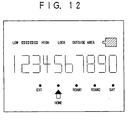
Fig. 12 is a diagram showing an example of display;
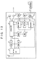
Fig. 13 is a block diagram showing the seventh
embodiment of the present invention;
Fig. 14 is a block diagram showing the construction of
a peripheral equipment in the seventh embodiment of the
present invention;
Fig. 15 is a block diagram showing the eighth
embodiment of the present invention;
Fig. 16 is a block diagram showing the construction of
a peripheral equipment in the eighth embodiment of the
present invention; and
Fig. 17 is a flow chart showing the operation of the
eighth embodiment of the present invention.
PREFERRED EMBODIMENTS OF THE INVENTION
Now, the embodiments of the present invention will be
described in conjunction with the accompanying drawings.
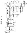
Fig. 1 is a block diagram showing the first embodiment
of the present invention, in which the present invention is
applied to an automobile telephone. Referring to Fig. 1, a
mobile communications equipment in this embodiment
comprises an antenna 1, and a radio-frequency signal
circuit 2 which receives a signal sent from another
equipment and transmits a signal directed toward the other
equipment and which processes the radio-frequency signals.
A demodulation circuit 3 demodulates the received signal,
while a modulation circuit 4 modulates the signal to-be-transmitted.
A speech controller 5 performs the filtering
of a speech signal received or to-be-transmitted, and also
performs the generation of a ringing tone or a warning
sound, the control of a speech route, etc. A modem circuit
6 demodulates system control data inserted between speech
data, into digital data, and it also modulates such digital
data. An analyzer 7 analyzes the received system control
information, and delivers the analyzed result to a main
controller 8. The analyzer 7 serves also as analysis means
for analyzing whether or not the communications of the
pertinent equipment with the other equipment are possible.
The main controller 8 controls the operation of the whole
equipment functioning as an automobile telephone set.
Display means 9 is, for example, a display unit made of
liquid crystal or the like. It displays the data of a
dialing input and the state of the automobile telephone set
proper. Shown at numeral 11 is a key circuit which serves
as an instruction input unit, and which accepts key inputs
for the dialing, etc. A setting unit 10 which serves as
setting means analyzes the depressions of the keys 11, and
delivers a set content to the main controller 8. A
microphone 12 and a speaker 13 constitute input/output
means, herein the handset of the telephone set. The
microphone 12 accepts an external signal, or converts the
voice signal into an electric signal. On the other hand,
the speaker 13 converts the signal demodulated by the
demodulation circuit 3, into a voice signal which is
externally given forth. The construction explained above
is similar to the main construction of an automobile
telephone set in the prior art. In this embodiment, the
automobile telephone set is additionally provided with a
detection/notification unit 21 and an LED (light emitting
diode) 22. The detection/notification unit 21 includes
detection means for detecting the state change between the
communicable state of the equipment and the incommunicable
state thereof on the basis of the analyzed result of the
analyzer 7, and notification means for giving notification
to the user of the equipment when the state change has been
detected by the detection means. Besides, the notification
means includes at least one constituent notification means
selected from among message output means for producing a
voice message as the notification, sound output means for
producing a notifying sound (beep) as the notification,
optical indication means for producing a notifying light as
the notification, and vibration means for producing
vibrations as the notification. In this embodiment, the
case of utilizing the LED 22 for emitting the notifying
light of the optical indication means is exemplified as the
notification means. The LED 22 can be kept continuously
lit or it can be flickered.
Whether or not the automobile telephone set lies
within a service area in which it is communicable, is
decided in such a way that the analyzer 7 receives the
system control data which are continually sent by a base
station installed on the ground. Among electric waves
received by the antenna 1, the signal at a specified
frequency (namely, in a specified radio channel) is
selected and amplified by the radio-frequency signal
circuit 2. The received signal is demodulated by the
demodulation circuit 3, and the demodulated signal is
delivered to the speech controller 5. In the speech
controller 5, the speech signal and the system control
signal are separated by filtering. The system control
signal is demodulated by the modem 6 into the digital data,
the content of which is thereafter analyzed by the analyzer
7. The main controller 8 controls the operation of the
whole automobile telephone set on the basis of the analyzed
result of the analyzer 7. Accordingly, whether or not the
telephone set lies within the service area can be decided
from the analyzed result of the analyzer 7. By way of
example, in a case where the telephone set has moved out of
the service area, the system control signal sent from the
base station cannot be normally received, and hence, the
output from the analyser 7 ceases or disappears. The main
controller 8 responsively controls the radio-frequency
signal circuit 2 so as to alter the radio channel to
another one and to check if a system control signal sent
from another base station is receivable on the new channel.
In a case where the system control signal cannot be picked
up in any of the radio channels set, the main controller 8
controls the display unit 9 so as to present a display
indicative of "outside the service area". Even after the
display has been presented, the main controller 8 continues
the receiving operation while changing the radio channel
until the system control signal becomes receivable, that
is, until the output of the analyzer 7 falls into the
normal state. In the situation where the communicable
radio channel is being searched for, the automobile
telephone set is capable of neither call origination nor
call termination. Therefore, even when the user depresses
the keys 11, the main controller 8 operates to hinder the
transmitting operation. In due course, when the system
control signal has been normally received, the analyzer 7
supplies the main controller 8 with the analyzed result.
The main controller 8 responsively controls the display
unit 9 so as to remove the display "OUTSIDE SERVICE AREA".
Thenceforth, the automobile telephone set is capable of
both call origination and call termination.
In this embodiment, the detection/notification unit 21
and the LED 22 are added to the prior-art automobile
telephone set. The output of the analyzer 7 is also
applied to the detection/notification unit 21, which
decides if the telephone set lies in the communicable area.
When the telephone set has become communicable, the
detection/notification unit 21 flickers the LED 22 or/and
produces the notifying sound by controlling the speech
controller 5, thereby notifying the user of the
communicability. The user can set the operation of the
detection/notification unit 21 via the setting unit 10 with
the keys 11. In this embodiment, whether or not the
notifying operation is to be performed can be set.
Now, the operation of the embodiment shown in Fig. 1
will be described in detail with reference to Figs. 1 and
2. Fig. 2 is a flow chart showing an example of the
operation of this embodiment.
As stated before, when the automobile telephone
terminal goes out of the service area, the system control
signal sent from the base station fails to be received.
Under this state of the telephone terminal, the main
controller 8 controls the display unit 9 so as to present
the display "OUTSIDE SERVICE AREA". Thereafter, it changes
the radio channel in order to search for a new base station
(step 50). When the system control signal has been
received during the search operation, whether or not the
base station has been caught is decided (step 51). This
decision is rendered in such a way that the analyzer 7
analyzes the content of the received signal to check if the
signal is the system control signal of the new base
station. When the received signal is not the system
control signal, the main controller 8 changes the radio
channel, and the routine returns to the step 50. In a case
where the system control signal has been received to enable
communication with the new base station, the display
"OUTSIDE SERVICE AREA"' presented on the display unit 9 is
removed (step 52). The operations thus far explained are
the same as in the prior-art automobile telephone terminal.
In this embodiment, when the analyzed result of the
analyzer 7 indicates the communication with the base
station, the detection means of the detection/notification
unit 21 detects that the state of the telephone terminal
has changed. Herein, when the state change is from the
incommunicable state into the communicable state, how the
operation of the detection/notification unit 21 is set is
checked (step 53). In this embodiment, whether or not the
detection/notification unit 21 is to perform the notifying
operation can be set through the setting unit 10.
Therefore, the detection/notification unit 21 first checks
if the notifying operation is set. The routine proceeds to
a step 54 when the notifying operation is set, and it is
directly ended when not. On condition that the notifying
operation is set, the detection/notification unit 21
flickers the LED 22, and it also controls the speech
controller 5 so as to emit the notifying sound (beep) from
the speaker 13 (step 54). Owing to the above operating
features operations, when the automobile telephone terminal
has picked up the new base station, not only is the display
"OUTSIDE SERVICE AREA" removed, but also the LED 22 is
flickered while at the same time, the beep is produced from
the speaker 13. Therefore, the operator of the telephone
terminal can know the usability thereof without confirming
the disappearance of the display "OUTSIDE SERVICE AREA"
from the display unit 9, so that the convenience of the
telephone terminal is enhanced. Especially in a case where
the action of seeing the display unit 9 is, in itself,
dangerous as in the case of driving an automobile in which
the telephone terminal is installed, this embodiment is
effective to enhance driving safety. Moreover, in this
embodiment, the notifying operation of the
detection/notification unit 21 can be set using the keys
11, so that the beep can be produced only when necessary.
The operating example shown in Fig. 2 corresponds to
the case where the user is notified of the entry from
out side the service area into this service area. It is
also possible to notify the user that the telephone
terminal has moved out of the service area. Fig. 3 is a
flow chart showing an operating example in the case where
the user is notified of the movement out of the service
area. Now, the operation of the embodiment in this case
will be described with reference to Figs. 1 and 3. When
the automobile telephone set has become distant from the
base station, electric waves weaken, and the system control
signal sent from the base station cannot be normally
received. Consequently, the output from the analyzer 7
ceases or disappears (step 55). The main controller 8
responsively controls the radio-frequency signal circuit 2
so as to alter the radio channel to another one and to
check if a system control signal sent from another base
station is receivable on this new channel (step 56). In a
case where the system control signal has been successfully
received, the main controller 8 registers the newly picked
up base station and ends the processing (step 58). On the
other hand, in a case where the system control signal
cannot be received on any of radio channels set, the main
controller 8 controls the display unit 9 so as to present
the display indicative of "outside the service area" (step
57) . On this occasion, the detection means of the
detection/notification unit 21 detects the state change
based on the movement out of the service area. After
having presented the display, the main controller 8 checks
if the setting unit 10 is set so as to perform the
notifying operation of the detection/notification unit 21
(step 53). The routine proceeds to a step 54 when the
notifying operation is set, and it is directly ended when
not. On condition that the notifying operation is set, the
detection/notification unit 21 flickers the LED 22, and it
also controls the speech controller 5 so as to emit the
notifying sound (beep) from the speaker 13 (step 54).
After the end of the above processing, the main controller
8 continues the receiving operation while changing the
radio channel until the system control signal becomes
receivable, that is, until the output of the analyzer 7
falls into the normal state. Owing to the above
operations, when the automobile telephone terminal has
missed the base station, not only is the display "OUTSIDE
SERVICE AREA" presented, but also the LED 22 is flickered
while at the same time, the beep is produced from the
speaker 13. Therefore, the operator of the telephone
terminal can know the unusability thereof without
confirming the display "OUTSIDE SERVICE AREA" on the
display unit 9, so that the convenience of the telephone
terminal is enhanced.
It is a matter of course that the convenience of the
telephone terminal is enhanced more by employing both the
operating examples shown in Figs. 2 and 3. In this case,
the aspect of notification can be made different between
the case of movement into the service area and the case of
movement out of the same, thereby permitting the user to
distinguish the movements from each other. Thus, the
convenience can be enhanced remarkably. By way of example,
it facilitates the distinction by the user that the
movement into the service area is chimed by the use of the
speaker 13, whereas the movement out of the service area is
buzzed. Needless to say, the flickering intervals or
lighting-up method of the LED 22 may well be changed for
the same purpose.
In the embodiment described above, the beep from the
speaker 13 and the flickering of the LED 22 are conjointly
utilized as the expedients of the notifications. However,
another notifying method may well be adopted, and the
notifying methods may well be selectable.
Fig. 4 is a block diagram showing the second
embodiment of the present invention. The points of
difference of this embodiment from the first embodiment
shown in Fig. 1 are that notification means can be
selected, and that a voice generator 33 is additionally
provided in order to use speech as a notifying sound.
Referring to Fig. 4, the voice generator 33 serves as
message output means, and it produces preset messages in
accordance with signals from the detection/notification
unit 21. A vibrator 31 as vibration means produces
vibrations, thereby notifying the user of the entry of the
mobile communications equipment into the service area.
Concretely, the vibrator 31 is any vibrators which utilize
an electric motor, a piezoelectric vibrator, an
electromagnet, etc. A switching circuit 32 operates to
select the constituent means of the notification means.
In the embodiment shown in Fig. 4, the notification
means includes three sorts of expedients; the production of
the message from the voice generator 33 (replacing the
production of the beep from the speaker 13 based on
controlling the speech controller 5), the flickering of the
LED 22, and the production of the vibrations based on the
operation of the vibrator 31. These notifying expedients
can be selected through the switching circuit 32. Thus,
the constituent notification means can be selected and
altered by the setting of the setting unit 10 from the keys
11. The operations of the other components are the same as
in the embodiment shown in Fig. 1.
Now, the operation of the embodiment shown in Fig. 4
will be described. When the user has moved from outside
the service area into this service area, the detection/notification
unit 21 detects the state change on the basis
of the change of the output of the analyzer 7. After the
detection, the unit 21 performs the notifying operation
through the switching circuit 32. Owing to the function of
the switching circuit 32, the three sorts of constituent
notification means can be selected in accordance with the
setting of the setting unit 10.
As described above, according to this embodiment,
the constituent means of the notification means can be
selected, so that the user can utilize the appropriate
constituent means in TPO (time, place, occasion) fashion.
By way of example, in a case where the user does not wish
for the emission of the sound in the vehicle, he/she can
select the notifying expedient based on the vibrations or
flickering. Also, in a case where the user is having
difficult noticing the state change with only the
flickering of the LED 22, he/she can select the notifying
expedient based on the vocal message, for example, "The
telephone set is usable.", "The telephone set has moved out
of the service area." or "The service area has changed.".
Therefore, this embodiment has the effect that the user can
select the desired setting.
In the embodiment described above, the convenience of
the telephone terminal is enhanced in the way that the
notifying methods are made selectable. However, the effect
of the present invention can be intensified when conditions
for performing the notifying operation are made selectable.
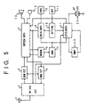
Fig. 5 is a block diagram showing the third embodiment of
the present invention. The point of difference of this
embodiment from the first embodiment shown in Fig. 1 is
that the conditions for performing the notifying operation
of the detection/
notification unit 21 are made selectable.
Referring to Fig. 5, timekeeping means 23 for measuring an
elapsed time period is connected to the
detection/
notification unit 21, making it possible to alter
the timing of performance of the notifying operation. In
addition, the radio-
frequency signal circuit 2 includes
electric field strength detection means for detecting the
electric field strength of the received signal. The
detection means of the
circuit 2 supplies the
detection/
notification unit 21 with information on the
electric field strength of the received signal. Thus, the
performance of the notifying operation can be controlled
depending upon the strength of the electric field of the
received signal. The items of the conditions for the
performance of the notifying operation which can be set in
the embodiment shown in Fig. 5 are listed in Table 1 below,
along with the set contents of the condition items. All
the conditions for the performance and the contents can be
set by operating the
setting unit 10 from the keys 11 which
serve as the instruction input means. The user can alter
the setting as required.
| Item of Condition | Set Contents | |
| 1. Number of Times of Performance | Setting #1: Notifying operation is not performed. |
| Setting #2: Performed at first time only. |
| Setting #3: Performed at all times. |
| 2. Electric field strength | Setting #1: Performed irrespective of field strength. |
| Setting #2: Performed at above predetermined level. |
| 3. Timing of Performance | Setting #1: Performed immediately. |
| Setting #2: Performed after lapse of predetermined time. |
In Table 1, the condition item #1 serves to set the
number of times of performance of the notifying operation.
The nonperformance of the notifying operation can also be
selecting by the setting #1 of the set contents. The
setting #2 is especially provided as one feature of this
embodiment in consideration of the convenience of the
communications equipment to the user, and it functions to
perform the notifying operation only one time after the
user's setting. By way of example, when the user wants to
call during the movement aboard the automobile outside the
service area, he/she may be notified of the establishment
of communicability only once. In this case, the setting #2
causes the notification means to give the notification at
the first state change only. Once the notifying operation
has been performed, it need not be inhibited, which is
convenient to the user. By the way, the number of times of
performance in the setting #2 may well be optionally set to
2 or more. Further, the setting #3 makes it possible to
give the notification at every state change.
The number of times of performance as the condition
item #1 can be stored and controlled within the
detection/notification unit 21. It is therefore to be
understood that the setting of this condition is also
applicable to the embodiments shown in Fig. 1 and Fig. 4.
The condition item #2 of the electric field strength
and the condition item #3 of the performance timing are
provided in order to verify that the communicable state of
the telephone terminal is stable. In general, at the
boundary between the interior and exterior of a service
area, received electric waves are of low field strength,
and they often disappear soon after the telephone terminal
has fallen into the communicable state. Particularly in
such a case where the telephone terminal cannot help moving
along the border part of the service area, the state
thereof is frequently changed between the communicable
state and the incommunicable state, and the notifying
operation might be frequently performed. In such a
situation, the condition items 2 and 3 are very effective.
The setting #2 of the condition item #2 signifies that the
notifying operation is performed when the electric field
strength measured by the detection means of the radio-frequency
signal circuit 2 has exceeded a certain
predetermined level. The conditioned performance can avoid
the unstable operation of the telephone terminal attributed
to the weak electric field near the border of the service
area. Further, with the setting #2 of the condition item
#3, the notifying operation is performed when the telephone
terminal has been checked by the timekeeper 23 as lying
within the service area continually for the predetermined
time period, and it can be verified that the telephone
terminal has fully entered the service area. By way of
example, in a case where the telephone terminal moves in a
mountainous district which is topographically complicated,
the propagation of electric waves changes complexly, and
hence, the electric field strength thereof can change
suddenly in a short time. In this case, it is effective to
utilize that combination of the setting #2 of the condition
item #2 and the setting #2 of the condition item #3 in
which the stable maintenance of the communicable state for
the predetermined time period is detected in terms of the
electric field strength.
Now, the operation of the third embodiment shown in
Fig. 5 will be detailed in conjunction with Fig. 6 or Fig.
7. Fig. 6 is a flow chart showing an example of the
operation in the case where the condition items #2 and #3
of the condition items listed in Table 1 are fixedly set
beforehand. On the other hand, Fig. 7 is a flow chart
showing another example of the operation in the case where
the user can set all the condition items listed in Table 1.
First, reference will be made to Figs. 5 and 6. As
stated before, when the automobile telephone terminal has
missed the service area, it becomes incapable of receiving
the system control signal sent from the base station.
Under this state of the telephone terminal, the main
controller 8 controls the display unit 9 so as to present
the display "OUTSIDE SERVICE AREA". Thereafter, it changes
the radio channel in order to search for a new base station
(step 50). When the system control signal has been
received during the search operation, the content thereof
is analyzed by the analyzer 7 to decide whether or not the
signal is the system control signal of a new base station
(step 51). When the new base station is not received, the
main controller 8 changes the radio channel, and the
routine returns to the step 50. In a case where the system
control signal has been received to pick up the new base
station, the display "OUTSIDE SERVICE AREA" presented on
the display unit 9 is removed (step 52). The analyzed
result of the analyzer 7 is also supplied to the
detection/notification unit 21, in which the pick up of the
base station is detected. Subsequently, the detection/notification
unit 21 checks the setting of the condition
item #1 (step 53'). That is, at the step 53', the
condition item #1 indicated in Table 1 is checked to decide
how the operation of the detection/notification unit 21 is
set. When the condition item #1 is set at the setting #2
or #3, the routine proceeds to a step 60, and when the
condition item #1 is set at the setting #1, the routine is
directly ended. At the setting #2 or #3, the timekeeper 23
is set or is started timekeeping (step 60). Thereafter, if
the electric waves of the base station can be stably
received for the preset time period is checked at steps 61
and 62. When the electric waves of the base station have
disappeared (step 62), it is decided that the service area
has been missed, and the display "OUTSIDE SERVICE AREA" is
presented (step 68). Thereafter, the routine returns to
the step 50. When the detection/notification unit 21 has
detected the lapse of the preset time period from the
output signal of the timekeeper 23, the step 61 is followed
by a step 63. Here, the detection/notification unit 21
checks the received electric field strength on the basis of
the electric field strength information supplied from the
radio-frequency signal circuit 2. As long as the electric
field strength is at the preset level or below, the step 63
and a step 64 are iterated. Meantime, when the electric
waves of the base station have disappeared (step 64),
resulting in the decision that the service area has been
missed, the display "OUTSIDE SERVICE AREA" is presented
(step 68), and the routine returns to the step 50. When
the electric field strength exceeds the preset level, the
step 63 is followed by a step 54'. At this step 54', the
detection/notification unit 21 flickers the LED 22, and it
controls the speech controller 5 so as to emit the beep
from the speaker 13. Thereafter, the condition item #1
indicated in Table 1 is checked (step 66). When the set
content of the condition item #1 is the setting #2, the
notifying operation ought to be performed only once.
Therefore, the set content is altered to the setting #1
(step 67) so as not to perform the notifying operation
again.
Owing to the above operations, also in this
embodiment, when the automobile telephone terminal has
picked up the new base station, not only is the display
"OUTSIDE SERVICE AREA" is removed, but also the LED 22 is
flickered while at the same time, the beep is produced from
the speaker 13. Therefore, the operator of the telephone
terminal can know the usability thereof without confirming
the removal of the display "OUTSIDE SERVICE AREA" from the
display unit 9, so that the convenience of the telephone
terminal is enhanced. Further, since the number of times
of performance, the electric field strength and the
performance timing are added as the conditions for giving
the notification, this embodiment is effective to enhance
the stability of the operation of the telephone terminal.
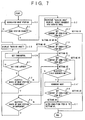
Next, the operation will be described with reference
to Figs. 5 and 7. The operation shown in Fig. 7 differs
from the above operation shown in Fig. 6 in that the user
can also set the condition items #2 and #3 freely. When
the telephone terminal has moved out of the service area,
the main controller 8 controls the display unit 9 so as to
present the display "OUTSIDE SERVICE AREA". Thereafter, it
changes the radio channel in order to search for a new base
station (step 50). When the system control signal has been
received during the search operation, the content thereof
is analyzed by the analyzer 7 to decide whether or not the
signal is the system control signal of a new base station
(step 51). When the signal is not the system control
signal of the new base station, the main controller 8
changes the radio channel, and the routine returns to the
step 50. In a case where the system control signal has
been received to pick up the new base station, the display
"OUTSIDE SERVICE AREA" presented on the display unit 9 is
removed (step 52). The analyzed result of the analyzer 7
is also supplied to the detection/notification unit 21,
which detects the picking up of the base station or the
state change. In accordance with the state change, the
detection/notification unit 21 checks the condition item #1
in Table 1 (step 53') as to how the notifying operation
thereof is set. When the condition item #1 is set at the
setting #2 or #3, the routine proceeds to a step 70, and
when the condition item #1 is set at the setting #1, the
routine is directly ended. At the setting #2 or #3 of the
condition item #1, the condition item #3 is checked (step
70). The step 70 is directly followed by a step 71 subject
to the setting #1 of the condition item #3, and it is
followed by steps 60 et seq. subject to the setting #2 of
the condition item #3. The timekeeper 23 is operated to
check if the electric waves of the base station can be
stably received for the preset time (steps 60 ∼ 62). The
processing of these steps 60 ∼ 62 is the same as in the
example illustrated in Fig. 6. At the step 71, the
condition item #2 is checked. The step 71 is directly
followed by a step 54' subject to the setting #1 of the
condition item #2, and it is followed by steps 63 et seq.
subject to the setting #2. As long as the electric field
strength of the received electric waves is at the preset
level or below, the steps 63 and 64 are iterated. The
processing of these steps 63 and 64 is the same as in Fig.
6. When the electric field strength has been OK'd in
excess of the preset level, the detection/notification unit
21 flickers the LED 22, and it controls the speech
controller 5 so as to emit the beep from the speaker 13
(step 54'). Thereafter, the condition item #1 indicated in
Table 1 is checked (step 66). When the set content of the
condition item #1 is the setting #2, the notifying
operation ought to be performed only once. Therefore, the
set content is altered to the setting #1 (step 67) so as
not to perform the notifying operation again.
Owing to the above operations, also in this
embodiment, when the automobile telephone terminal has
picked up the new base station, not only is the display
"OUTSIDE SERVICE AREA" removed, but also the LED 22 is
flickered while at the same time, the beep is produced from
the speaker 13. Therefore, the operator can know the
usability of the telephone set without confirming the
disappearance of the display "OUTSIDE SERVICE AREA" on the
display unit 9, so that the convenience of the telephone
terminal is enhanced. Further, the checks of the number of
times of performance, the electric field strength and the
continuity of the state are added as the conditions for
giving the notification. Accordingly, this embodiment
brings forth the effect that the stability of the operation
of the telephone terminal can be enhanced, and the effect
that the user can alter the set conditions more
conveniently as demands.
In the embodiments thus far described, the automobile
telephone sets have been referred to. It is to be
understood, however, that the present invention is
applicable to any mobile communications terminal comprising
analysis means for analyzing electric waves sent from a
base station, detection means for detecting if the terminal
lies within a service area, from the analyzed result of the
analysis means, and notification means for giving
notification to the user of the terminal in response to the
output of the detection means. That is, the present
invention is effective for any of the terminals of systems
wherein a radio communications channel is established
between the mobile terminal and a relay station or an
exchange which is installed on the ground or in a
satellite. Concrete examples of the terminals are an MCA
(multichannel access) terminal, a second-generation
cordless telephone set and a digital cellular terminal
which have certain limited service areas.
Fig. 8 is a block diagram showing an example of a
digital mobile communications terminal which transmits all
speech and data in terms of digital signals. Referring to
Fig. 8, the communications equipment in this embodiment
comprises an
antenna 1, and a radio-
frequency signal
circuit 2 which receives a signal sent from another
equipment and transmits a signal directed toward the other
equipment and which processes the radio-frequency signals.
A
demodulation circuit 3 detects the received signal
synchronously, while a
modulation circuit 4 modulates the
signal to-be-transmitted orthogonally. A
modem circuit 6
demodulates the synchronously-detected signal into digital
data. The
modem circuit 6 also functions to correct errors
and to convert digital data into the orthogonal signal to-be-transmitted.
A
speech controller 5 quantizes the speech
signal received or to-be-transmitted, and also performs the
processing of data compression/expansion, the generation of
a ringing tone or a warning sound, the control of a speech
route, etc. An
analyzer 7 serves as analysis means for
analyzing whether or not the communications of the
pertinent equipment with the other equipment are possible.
A
main controller 8 controls the operation of the whole
equipment functioning as an automobile telephone set.
Display means 9 is, for example, a display unit made of
liquid crystal or the like. It displays the data of a
dialing input and the state of the automobile telephone set
proper. Shown at numeral 11 is a key circuit which serves
as an instruction input unit, and which accepts key inputs
for the dialing, etc. A setting
unit 10 which serves as
setting means analyzes the depressions of the keys 11, and
delivers a set content to the
main controller 8. A
microphone 12 and a
speaker 13 constitute input/output
means, herein the handset of the telephone set. The
microphone 12 accepts an external signal, or converts the
voice signal into an electric signal. On the other hand,
the
speaker 13 converts the signal demodulated by the
demodulation circuit 3, into a voice signal which is
externally emitted. The construction explained above is
similar to the main construction of a digital mobile
communications terminal in the prior art. In this
embodiment, the automobile telephone set is additionally
provided with a
network registration unit 24. The
network
registration unit 24 is a component in which the sorts of
serviceable or available networks are registered. Table 2
below indicates examples of the registered sorts of
networks. Referring to Table 2,
Network #1 is a
communications network or circuit through which the
pertinent equipment communicates with a preset host station
as in a cordless telephone system,
Network #2 is a personal
network or circuit which is individually provided for
private communications,
Network #3 is a public radio
network which has been individually subscribed to with a
network offerer,
Network #4 is another public radio network
which is usable, and
Network #5 is a special network such
as a satellite circuit which is usable through a satellite
or an emergency circuit which is opened in case of
emergency. Whether or not any of the networks is usable,
is decided in such a way that the
analyzer 7 analyzes the
output system control data of the
modem 6 while comparing
it with the registered contents of the
network registration
unit 24.
| Network No. | Name of Network | Remarks |
| Network # |
| 1 | Base circuit | Connected with specified host station. |
| Network #2 | Personal circuit | Individual network such as private radio system. |
| Network #3 | Subscriber network | Public network subscribed to. |
| Network #4 | Roaming network | Another public network. |
| Network #5 | Special network | Satellite link, emergency circuit, or the like. |
Now, the operation of the embodiment shown in Fig. 8
will be described. Among electric waves received by the
antenna 1, only the signal of a specified frequency ("radio
channel") is selected and amplified by the radio-frequency
signal circuit 2. The received signal is subjected to the
synchronous detection by the demodulation circuit 3, and
the detected signal is supplied to the modem 6. The modem
6 demodulates the input signal into the digital data, the
speech data of which is delivered to the speech controller
5 and the system control signal of which is delivered to
the analyzer 7 and has its content analyzed. Here, the
system control data is continually sent from the host
station or a transponder, and it contains peculiar
recognition data or classification code data so as to
distinguish the sort of the corresponding network. The
analyzer 7 decides whether or not the network is usable, by
analyzing the system control data in comparison with the
registered contents of the network registration unit 24,
and it delivers the analyzed result to the main controller
8 as well as the display unit 9. The main controller 8
controls the operation of the whole automobile telephone
set on the basis of the analyzed result of the analyzer 7.
The speech data is subjected to the data expansion and then
converted into an analog signal by the speech controller 5,
and the analog signal is converted into a voice signal by
the speaker 13. The analyzed result of the analyzer 7 is
also supplied to the display unit 9 so as to display the
sort of the usable network. Fig. 12 shows an example of
the display of the display unit 9. The sorts of networks
as listed in Table 2 are indicated as shown in the lower
part of Fig. 12, and the lamps of the usable networks are
lit up or flickered. Besides, the electric field strength
of the received signal and the display "OUTSIDE SERVICE
AREA" may well be displayed as shown in the upper part of
Fig. 12.
Likewise to any of the foregoing embodiments, the
embodiment shown in Fig. 8 may well be provided with
detection/notification means including detection means and
notification means. In this case, the analyzer 7 decides
the sort of the communicable network from the signal
received by the radio-frequency signal circuit 2. The
detection means detects the change of the sort of the
communicable network from the analyzed result of the
analyzer 7. The notification means notifies the user of
the telephone set that the sort of the network has changed,
in response to the detection of the detection means.
Alternatively, the analyzer 7 analyzes the
communicable networks from the signals received by the
radio-frequency signal circuit 2, with reference to the
network registration unit 24. The detection means detects
the state changes of the respective networks between the
communicable and incommunicable states thereof, on the
basis of the analyzed results of the analyzer 7. The
notification means notifies the user of the state changes
of the respective networks detected by the detection means.
These contrivances bring forth the effect that the
user can confirm the used network.
Fig. 9 is a block diagram showing the second example
of the digital mobile communications terminal. The point
of difference of this embodiment from the embodiment shown
in Fig. 8 is that a detection/notification unit 21, an LED
22, a voice generator 33 and a priority setting unit 25 are
additionally provided, whereupon when a network set in the
setting unit 10 has become usable, the detection/notification
unit 21 notifies the user of the
communicability by the flickering of the LED 22 or/and the
output message of the voice generator 33. Referring to
Fig. 9, the priority setting unit 25 sets priority levels
for the networks registered in the network registration
unit 24, and it selects the required one of the networks in
conformity with the setting. The detection/notification
unit 21 detects if the network selected by the priority
setting unit 25 has fallen into a communicable or
incommunicable state, from the change of the analyzed
result of the analyzer 7, and it notifies the user of the
state change. In other words, the detection/notification
unit 21 includes detection means for detecting the change
between the communicable and incommunicable states of the
network selected by the priority setting unit 25, on the
basis of the analyzed result of the analyzer 7, and
notification means for notifying the user of the state
change detected by the detection means. The voice
generator 33 produces any necessary preset messages in
accordance with the output signal of the detection/notification
unit 21. This voice generator 33 forms part
of message output means, and the vocal message is emitted
by the speaker 13. The operations of the other components
are the same as in the embodiment shown in Fig. 8.
The embodiment shown in Fig. 9 operates as described
below. The detection/notification unit 21 can decide
whether or not the network registered in the network
registration unit 24 lies within a service area, from the
analyzed result of the analyzer 7. By way of example, in a
case where the digital mobile communications terminal has
moved out of the service area, the system control signal
sent from the host station or the base station cannot be
normally received, and hence, the output from the analyzer
7 ceases or disappears. Further, when the sort of the
connectable network has changed, the peculiar recognition
data or classification code data for discriminating the
sort of the network as contained in the system control data
changes, so that the detection/notification unit 21 can
know the change of the network from the change of the
output of the analyzer 7. When the output of the analyzer
7 has ceased, the main controller 8 controls the radio-frequency
signal circuit 2 so as to alter the radio channel
to another one and to check if a system control signal sent
from another base station is receivable. In a case where
the system control signal cannot be picked up on any of the
radio channels set, the main controller 8 controls the
display unit 9 so as to present the display indicative of
"outside the service area'. Even after the display has
been presented, the main controller 8 continues the
receiving operation while changing the radio channel until
the system control signal becomes receivable, that is,
until the output of the analyzer 7 falls into the normal
state. In the situation where the communicable radio
channel is being searched for, the digital automobile
telephone set is capable of neither call origination nor
call termination. Therefore, even when the user depresses
the keys 11, the main controller 8 operates to hinder the
transmitting operation. In due course, when the system
control signal of any of the networks registered in the
network registration unit 24 has been normally received,
the analyzer 7 supplies the main controller 8 with the
analyzed result. The main controller 8 responsively
controls the display unit 9 so as to remove the display
"OUTSIDE SERVICE AREA". Thenceforth, the digital
automobile telephone set is capable of both call
origination and call termination. In this embodiment, the
output of the analyzer 7 and that of the priority setting
unit 25 are supplied to the detection/notification
controller 21, whereby the detection/notification
controller 21 decides whether or not the network selected
by the priority setting unit 25 is usable. As the result
of the decision, the detection/notification controller 21
can flicker the LED 22 or/and emit the notifying message
through the control of the voice generator 33, to notify
the user that the digital mobile communications equipment
has become communicable or incommunicable or that the
usable network has changed. The user can set the operation
of the detection/notification unit 21 via the setting unit
10 with the keys 11. In this embodiment, whether or not
the notifying operation is to be performed can be set.
Now, the operation of the embodiment shown in Fig. 9
will be described in detail with reference to Figs. 9 and
10. Fig. 10 is a flow chart showing the operation of this
embodiment.
As stated before, when the digital mobile
communications terminal has missed the service area, the
system control signal sent from the base station fails to
be received. Under this state of the communications
terminal, the main controller 8 controls the display unit 9
so as to present the display "OUTSIDE SERVICE AREA".
Thereafter, it changes the radio channel in order to search
for a new base station (step 80). When the system control
signal has been received during the search operation, the
content of the received signal is analyzed by the analyzer
7, to decide if the signal is the system control signal of
the new base station (step 81). When the received signal
is not the system control signal of the new base station,
the main controller 8 changes the radio channel, and the
routine returns to the step 80. In a case where the system
control signal has been received to pick up the new base
station, the display "OUTSIDE SERVICE AREA" presented on
the display unit 9 is removed (step 82). The operations
thus far explained are the same as in the prior-art
automobile telephone terminal. In this embodiment, when
the analyzed result of the analyzer 7 indicates the picking
up of the base station, it is also delivered to the
detection/notification controller 21. The detection/notification
controller 21 is supplied with the analyzed
result of the analyzer 7 and the output of the priority
setting unit 25, and it decides whether or not the network
selected by the priority setting unit 25 has become usable
(step 83). When the decision indicates the usability of
the selected network, the detection/notification controller
21 flickers the LED 22, and it also controls the voice
generator 33 so as to emit the notifying message from the
speaker 13 (step 84), thereby notifying the user of the
state change into the communicable state. Alternatively,
the detection/notification controller 21 may include
vibration means so as to give the notification in terms of
vibrations. It may well include sound output means so as
to give the notification in terms of a notifying sound
(beep). Likewise to the foregoing embodiments, this
embodiment may well be so contrived that the constituent
means of the notification means to be used for the
notification can be selectively set.
These operations make it possible to register
predetermined sorts of networks, to endow the sorts of
networks with priority levels, to analyze whether or not
the network of higher priority level is communicable, to
detect the state change of the network of higher priority
level from the incommunicable state of this network into
the communicable state thereof, and to give notification in
response to the state change of the network of higher
priority level.
Owing to the above operational features, when the
digital mobile communications terminal has picked up the
network set in the priority setting unit 25 beforehand, the
LED 22 is flickered while at the same time, the notifying
message is produced from the speaker 13. Therefore, the
operator of the telephone terminal can know the usability
thereof without confirming the disappearance of the display
"OUTSIDE SERVICE AREA" or the appearance of a display
indicative of the usability of the network on the display
unit 9, so that the convenience of the telephone terminal
is enhanced. Especially in a case where the action of
seeing the display unit 9 is, in itself, dangerous as in
the case of driving an automobile in which the telephone
terminal is installed, this embodiment is effective to
enhance the driving safety.
The operating example shown in Fig. 10 corresponds to
the case where the user is notified of the entry from
outside the service area into this service area. The user
can also be notified of the movement of the telephone
terminal out of the service area as in the embodiment shown
in Fig. 3, with ease in such a way that the detection/notification
unit 21 detects the outward movement on the
basis of the output of the analyzer 7.
As described above, according to this embodiment, the
control signal of the network selected by the user is
analyzed to decide that the selected network has fallen
into the usable or unusable state, and the LED 22 is
flickered while at the same time, the notifying message is
emitted from the speaker 13. Therefore, the operator can
know the state change of the selected network into the
usable or unusable state without seeing the display of the
display unit 9, so the convenience of the telephone
terminal is enhanced. In particular, since the user can be
notified of the state change as to the selected sort of
network, this embodiment is favorable in the case of, for
example, selecting a network of lower charge rate such as
the personal circuit. Moreover, in the present invention,
the notifying operation is controlled on the basis of the
result obtained by analyzing the system control signal.
Therefore, notification can also be given when the content
of the system control information has changed. By way of
example, in a system in which the system control
information contains data indicative of a region where an
earth station is located, the region where the telephone
terminal is moving may well be decided and then notified to
the user. In this case, when the telephone terminal is
furnished with calculation means for calculating a
communications toll from the regional data, the
detection/notification unit 21 can detect and notify the
user, for example, that the communications toll has become
within a designated amount of money. Of course, this
embodiment is also effective to enhance the safety in the
case where the action of seeing the display unit 9 is, in
itself, dangerous as in the case of driving the automobile.
Besides, in this case, the convenience can be more enhanced
in such a way that the aspect of notification is made
different between at the case of movement into the service
area and the case of movement out of the same, thereby
permitting the user to distinguish the movements from each
other. By way of example, it facilitates the distinction
by the user that the movement into the service area is
notified by emitting a message "The telephone terminal is
usable." from the speaker 13, whereas the movement out of
the service area is notified by emitting a message "The
service area has been left". Needless to say, the
flickering intervals or lighting-up method of the LED 22
may well be changed for the same purpose.
In any of the foregoing embodiments, when the
communications terminal has moved into or/and out of the
service area, only notification of the fact is given.
However, another operation may well be performed at the
same time. Fig. 11 is a block diagram showing an
embodiment of a digital mobile communications terminal
which automatically performs a dialing operation at the
time of entry into the service area. As compared with the
embodiment shown in Fig. 9, the embodiment shown in Fig. 11
is additionally provided with a dialing starter 26, a
checker 27, a memory 28 and a dialing confirmation unit 29.
The other components are the same as in Fig. 9. Referring
to Fig. 11, the memory 28 stores therein the telephone No.
or recognition No. of an opposite party to-be-dialed. The
dialing starter 26 works on the main controller 8 so as to
dial the opposite party stored in the memory 28. The
checker 27 checks the operating conditions of the dialing
starter 26. More specifically, it checks the conditions
from the detected result of the detection/notification unit
21 and the setting of the setting unit 10 so as to operate
the dialing starter 26 when the conditions are met. The
dialing confirmation unit 29 is started by the checker 27
in accordance with the setting of the setting unit 10.
This unit 29 emits a vocal message so as to ask the user
whether or not the dialing operation is to be performed.
It receives the reply of the user in terms of data afforded
by depressing the keys 11 or a voice afforded through the
microphone 12 as well as the speech controller 5, and
delivers the confirmed result to the checker 27.
The embodiment shown in Fig. 11 operates as described
below. When the mobile communications terminal having
initially moved out of the service area re-enters the
service area, the system control signal becomes receivable,
and the analyzer 7 delivers the analyzed result to the main
controller 8 as well as the detection/notification unit 21.
Upon receiving the analyzed result, the
detection/notification unit 21 checks the usability of one
of the networks registered in the network registration unit
24 as selected by the priority setting unit 25. When the
unit 21 decides the selected network to be usable as the
result of the check, it notifies the user of the
communicability by flickering the LED 22 or/and emitting
the notifying message from the speaker 13 through the
control of the voice generator 33. The operations thus far
explained are the same as in the embodiment shown in Fig.
9. Upon detecting that the network selected by the
priority setting unit 25 has become usable, the
detection/notification unit 21 delivers the detected result
to the checker 27. The checker 27 responsively checks the
conditions set in the setting unit 10. The conditions to
be set in the setting unit 10 are whether or not a hands-free
function is to be implemented, whether the user's
reply is to be the key input or the vocal answer, and so
forth. Here in this embodiment, it is possible to set
whether or not the autodialing operation is to be
performed, and whether or not the dialing operation is to
be confirmed by the user. The checker 27 starts the
dialing confirmation means 29 subject to the set conditions
of the setting unit 10 that the autodialing operation is to
be performed and that the dialing operation is to be
confirmed by the user. The dialing confirmation means 29
responsively emits the message, for example, "May ····· be
called?", thereby requesting the user to confirm the
dialing. When the user has depressed the keys 11 or
replied vocally as the confirmation, the dialing
confirmation means 29 delivers the confirmed result to the
checker 27. Then, the checker 27 supplies a start signal
to the dialing starter 26, which works on the main
controller 8 so as to start the dialing operation.
As stated above, according to this embodiment, the
desired opposite party is automatically dialed at the entry
of the telephone terminal into the service area by merely
setting the telephone No. or recognition No. of the
opposite party in the memory 28 and the condition of the
performance of the autodialing operation in the setting
unit 10 beforehand during the movement of the telephone
terminal in an incommunicable region. Therefore, this
embodiment is effective to enhance the convenience of the
telephone terminal. Moreover, since the confirmation of
the dialing operation can be set, the performance of any
unfavorable dialing can be prevented in, for example, a
case or a place where the user cannot call. Especially
when the hands-free function is conjointly utilized, the
confirming operation and the keying operation can be
dispensed with during the driving of the automobile in
which the telephone terminal is installed. Therefore, this
embodiment is effective to enhance driving safety.
Incidentally, the autodialing function included in
this embodiment is also applicable to the foregoing
embodiments shown in Fig. 1, Fig. 4 and Fig. 5. More
specifically, the autodialing function can be realized in
each of the foregoing embodiments in the following way:
The key circuit 11 is adapted to further accept the
identification information of the other equipment to
communicate, and an instruction for commencing the
communications. Besides, each foregoing embodiment is
further provided with a memory which stores the
identification information therein, a starter which starts
the commencement of the communications in accordance with
the identification information stored in the memory, and a
checker which commands the starter to start the
communications commencement in response to the state change
from the incommunicable state into the communicable state
as detected by the detection means, on condition that the
communications commencement instruction has been accepted
by the key circuit 11 in the incommunicable state.
In any of the above embodiments, the notifying
operation is performed in the mobile communications
equipment proper. It is also possible, however, for
detection information to be output from the mobile
communications equipment and for a peripheral equipment
connected to the mobile communications equipment to perform
a notifying operation on the basis of the detection
information. In this case, the notifying operation can be
performed by a function included in the peripheral
equipment. By way of example, in a case where a TV
(television) set is mounted as the peripheral equipment, a
TV screen can be flickered. Besides, in a case where a FAX
(facsimile) equipment is mounted, it can be started.
Further, in a case where a car stereo is mounted, a
notifying sound (beep), a vocal message or the like can be
emitted from the car stereo. The mounted peripheral
equipment realizes a notifying method which cannot be
performed by only the mobile communications equipment
proper. Now, there will be described a mobile
communications system in the case where such a peripheral
equipment is mounted.
Fig. 13 is a block diagram showing an example in which
the peripheral equipment is connected to the mobile
communications terminal. Referring to the figure, numeral
100 indicates the mobile terminal. The peripheral
equipment 101 connected to the mobile terminal 100 can give
notification to the user. Examples of the peripheral
equipment are a navigation equipment, a car TV set, a
portable TV set, etc. each of which has a display function,
and the car stereo, a headphone stereo, a tape recorder, a
hearing aid, etc. each of which has a sounding function.
The mobile terminal 100 is constructed substantially
similarly to the embodiment shown in Fig. 1, and identical
numerals are respectively assigned to the blocks of the
terminal 100 having the same operations as in Fig. 1. This
embodiment shown in Fig. 13 differs from the embodiment
shown in Fig. 1 in that an output unit 34 is added and has
its output connected to the peripheral equipment 101. The
output unit 34 receives at least one piece of information
among control information for controlling the peripheral
equipment 101 as delivered from the main controller 8,
electric field strength information delivered from the
radio-frequency signal circuit 2, and notification
information for notifying the user of the state change
between the communicable and incommunicable states as
delivered from the detection/notification unit 21. The
output unit 34 turns the information into a signal s1 which
is compatible with the peripheral equipment 101, and
transfers the signal s1 to the peripheral equipment 101.
An example of construction of the peripheral equipment
101 is shown in Fig. 14. A data input unit 38 serving as
input means receives the signal s1 transferred from the
output unit 34 of the mobile terminal 100. A data analyzer
37 serving as analysis means analyzes the transferred
signal, and extracts the information. A controller 36
controls the whole peripheral equipment 101. A peripheral
unit 41 performs the original operation of the peripheral
equipment 101. A display circuit 39 serves to present a
display on a display unit 43, and a beep generator 40
generates a beep through a speaker 42. As the display
circuit 39 and the display unit 43, ones with which the
peripheral equipment 101 is furnished are respectively
utilized. In a case where the peripheral equipment 101 is
not furnished a display circuit or unit, they may well be
omitted from the illustrated construction. The notifying
operation can be previously determined in accordance with
the sort of pertinent peripheral equipment 101. Such a
peripheral equipment includes, at least, input means for
receiving the notifying information from the output means
of the associated mobile communications equipment, analysis
means for analyzing the content of the notifying
information accepted by the input means, and notification
means for performing a predetermined notifying operation on
the basis of the analyzed result of the analysis means.
Now, the operation of this embodiment will be
described with reference to Figs. 13 and 14. As explained
in relation to the foregoing embodiment shown in Fig. 1,
the analyzer 7 analyzes the signal received by the radio-frequency
signal circuit 2 in the state in which the mobile
terminal 100 in Fig. 13 is incommunicable, that is, in
which the base station is not picked up. When the base
station has been caught, the detection means of the
detection/notification means 21 detects the state change of
the mobile terminal 100 on the basis of the analyzed result
of the analyzer 7. Thereafter, the notification means of
the detection/notification unit 21 transfers the notifying
information as the signal s1 to the peripheral equipment
101 through the output unit 34 in order to notify the state
change from the incommunicable state into the communicable
state. The notifying information is delivered to the data
analyzer 37 of the peripheral equipment 101 through the
data input unit 38 thereof, and is recognized as such in
this data analyzer. Then, the data analyzer 37 informs the
controller 36 that the notifying information has been
transferred to the peripheral equipment 101. In the case
where the display unit 43 is included in the navigation
equipment, the car TV set, the portable TV set, or the
like, the controller 36 having received the notifying
information controls the display circuit 39 so as to
flicker the screen of the display unit 43 or to display the
message thereon. On the other hand, in the case where the
speaker 42 as speech output means is included in the car
stereo, the headphone stereo, the tape recorder, the
hearing aid, or the like, the controller 36 controls the
beep generator 40 so as to emit the beep from the speaker
42. In this way, the peripheral equipment 101 can notify
the user that the mobile terminal 100 has become
communicable. Although the changes of the display and the
generation of the beep have been exemplified here, it is a
matter of course that a function peculiar to such a
peripheral equipment may well be utilized. Any of
multifarious notifying methods can be obtained in such a
manner that a vocal message is output by a voice producing
function, that music is played by a melody producing
function, and that vibrations are developed by a vibration
producing function.
Besides, a voice input/output terminal such as
microphone terminal or headphone terminal can be utilized
as the interface between the mobile terminal and the
peripheral equipment. In this case, vocal information to
be emitted may well be produced in the mobile terminal and
then transferred to the peripheral equipment.
Alternatively, specific signals may well be stipulated
between the mobile terminal and the peripheral equipment
beforehand, so as to give notification by a corresponding
one of predetermined notifying methods when any of the
specific signals has been detected.
Meanwhile, the peripheral equipment may well be one
having a communicating function, for example, the FAX
(facsimile) equipment or a data communications terminal.
Fig. 15 is a block diagram showing an example in which the
peripheral equipment having the communicating function is
connected to the mobile communications terminal equipment.
Referring to the figure, numeral 100 indicates the mobile
terminal. The peripheral equipment 102 connected to the
mobile terminal 100 is the FAX equipment or the like having
the communicating function. The mobile terminal 100 is
constructed substantially similarly to the embodiment shown
in Fig. 13, and identical numerals are respectively
assigned to the blocks of the terminal 100 having the same
operations as in Fig. 13. The points of difference of this
embodiment shown in Fig. 15 from the foregoing embodiment
shown in Fig. 13 are that an input unit 35 is added and is
supplied with the output signal s2 of control information
from the peripheral equipment 102, and that the
communications signals s3 of the peripheral equipment 102
are supplied to and from the speech controller 5 in order
to connect the peripheral equipment 102 with the radio
channel of the mobile terminal 100. The input unit 35
functions to supply the setting unit 10 with the signal s2
transferred from the peripheral equipment 102, likewise to
the operation of the key circuit 11. Thus, the mobile
terminal 100 can be controlled likewise to the keying
operation by the peripheral equipment 102. The
communications signals s3 are the output/input signals of
transmission/reception information in the peripheral
equipment 102. The output signal of the transmission
information is sent to the opposite terminal of the
communications over the radio channel via the speech
controller 5, modulation circuit 4, radio-frequency signal
circuit 2 and antenna 1. Contrariwise, the input signal of
the reception information is sent to the peripheral
equipment 102 via the antenna 1, radio-frequency signal
circuit 2, demodulation circuit 3 and speech controller 5.
The output unit 34 receives control information for
controlling the peripheral equipment 102 as delivered from
the main controller 8, electric field strength information
delivered from the radio-frequency signal circuit 2, and
notification information for notifying the user of the
state change between the communicable and incommunicable
states as delivered from the detection/notification unit
21. The output unit 34 turns the information into a signal
s1, and transfers the signal s1 to the peripheral equipment
102.
An example of construction of the peripheral equipment
102 is shown in Fig. 16. A data input unit 38 receives the
signal s1 transferred from the output unit 34 of the mobile
terminal 100. A data analyzer 37 analyzes the transferred
signal, and extracts the information. A controller 46
controls the whole peripheral equipment 102. A peripheral
unit 47 performs the original operation of the peripheral
equipment 102. A display circuit 39 serves to present a
display on a display unit 43, and a beep generator 40
generates a beep through a speaker 42. A dialing starter
45 starts the dialing function of the controller 46 upon
receiving the notifying information from the data analyzer
37. A modem 44 converts digital information into an analog
signal (the signal s3), and converts an analog signal (the
signal s3) into digital information. A control data output
unit 48 transfers control data (the signal s2) for
controlling the mobile terminal 100 from the peripheral
equipment 102. In this case, such a peripheral equipment
is further provided with an instruction input unit which
accepts the identification information of the other mobile
communications equipment, a memory which stores therein the
identification information accepted by the instruction
input unit, a start command unit which commands the
associated mobile communications equipment to start the
commencement of the communications in accordance with the
identification information stored in the memory, and a
checker which is endowed with an autodialing mode that
causes the start command unit to operate in response to the
state change from the incommunicable state into the
communicable state as detected on the basis of the output
of the analysis means, on condition that the communications
commencement instruction has been accepted by the
instruction input unit in the incommunicable state.
An ordinary interface (for example, "X. 25" in the
case of packet communications) is utilized as the interface
between the mobile terminal 100 and the peripheral
equipment 102 such as FAX equipment or data communications
terminal. The communications are done in such a way that
specified signal patterns to be transmitted and received
are stipulated in the signals s1 and s2 beforehand.
Now, the operation of the embodiment shown in Figs. 15
and 16 will be described with reference to Fig. 17. Fig.
17 is a flow chart for explaining the operation of this
embodiment. First, the user performs a dialing operation
with the peripheral equipment 102 (step 85). Then, the
controller 46 responsively controls the control data output
unit 48 so as to supply the mobile terminal 100 with the
control signal s2 for ascertaining if the communications
are possible. On the side of the mobile terminal 100, the
main controller 8 having received the control signal s2
through the input unit 35 as well as the setting unit 10
transfers the signal s1 indicating if the communications
are possible, from the output unit 34 to the peripheral
equipment 102. On the side of the peripheral equipment
102, the signal s1 is received by the data input unit 38,
the content of this signal is analyzed by the data analyzer
37, and the analyzed result is received by the controller
46. When the received result indicates the
communicability, the controller 46 decides that the dialing
is possible (step 86). In this case, the controller 46
transfers dialing information to the mobile terminal 100
through the control data output unit 48 at a step 87.
Thus, the dialing operation is executed. After the
peripheral equipment 102 has been connected with the other
equipment over the radio channel, it transmits and receives
the signals s3 through the modem 44, thereby to communicate
with the opposite equipment (step 88).
On the other hand, in a case where the communications
are impossible, that is, where the dialing has been decided
impossible at the step 86, the routine proceeds to a step
89. In this case, the controller 46 controls the display
circuit 39 so as to display "ON STANDBY TO DIAL" on the
display unit 43 at the step 89, thereby to inform the user
that the dialing is impossible. Thenceforth, it is waited
at a step 90 there is a wait for the dialing start unit 45
to become operable. As explained in relation to the
foregoing embodiment shown in Fig. 1, the analyzer 7
analyzes the signal received by the radio-frequency signal
circuit 2 in the incommunicable state in which the base
station is not picked up. When the base station has been
picked up, the detection means of the
detection/notification means 21 detects the state change of
the mobile terminal 100 on the basis of the analyzed result
of the analyzer 7. Thereafter, the notification means of
the detection/notification unit 21 transfers the notifying
information (the signal s1) to the peripheral equipment 102
through the output unit 34 in order to notify the state
change from the incommunicable state into the communicable
state. The notifying information is delivered to the data
analyzer 37 of the peripheral equipment 102 through the
data input unit 38 thereof, and is recognized as such in
this data analyzer. Then, the data analyzer 37 informs the
dialing start unit 45 of the recognition of the notifying
information. The dialing start unit 45 responsively
informs the controller 46 that the notifying information
has been transferred to the peripheral equipment 102, and
it also starts the dialing operation. Then, the routine
proceeds to the step 87, at which the controller 46
transfers dialing information to the mobile terminal 100
through the control data output unit 48. Thus, the dialing
operation is executed. After the peripheral equipment 102
has been connected with the other equipment over the radio
channel, it communicates with the opposite equipment
through the modem 44 (step 88).
As thus far explained, according to this embodiment,
once the user has performed the dialing operation of the
peripheral equipment 102 irrespective of whether or not the
mobile terminal 100 is communicable, the communications are
automatically commenced upon establishment of the
communicable state. Accordingly, this embodiment brings
forth the effect that the user is freed from repeatedly
having to confirm the state of the mobile terminal 100.
Moreover, a notifying sound (beep) or the like may well be
employed for informing the user that the dialing operation
has been started. Further, insofar as the information can
be transmitted, any expedient may be employed for the
connection between the mobile terminal 100 and the
peripheral equipment 102. Examples of the expedient are
optical transmission, radio transmission and acoustic
transmission.
As described above, according to the present
invention, the state change of a mobile communications
equipment based on the movement thereof, such as the state
change from outside a service area into the same, can be
detected and notified. The user of the equipment can know
the communicability thereof without expressly checking the
display of a display unit, so that the convenience of the
equipment is enhanced. Especially, even when the user is
driving an automobile, he/she can confirm his/her entry
into the service area without any hindrance to his/her
driving operation, so that the driving safety is enhanced.