BACKGROUND OF THE INVENTION
The present invention relates to a novel magnet block assembly
for an insertion device which is inserted into the linear part of an electron
accelerator or electronic storage ring to emit a synchrotron radiation
of high intensity. More particularly, the invention relates to an
assembly of permanent magnet blocks for a compact-size insertion device
of a small period length having a large number of periods despite
the compactness as well as to a method for the magnetization of the
magnet blocks in the assembly.
As is known, an insertion device is a device inserted into the
linear part of an electron accelerator or electronic storage ring to emit
a synchrotron radiation of high intensity. An insertion device of the
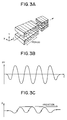
prior art is a device, as is illustrated in Figure 3A by a perspective
view, having a structure of a magnet block assembly consisting of at
least two arrays of permanent magnet blocks disposed to oppose each
the other to form an air gap therebetween. When the directions of
magnetization of the individual permanent magnet blocks are as
shown in Figure 3A indicated by the small arrows on the end surfaces
of the respective magnet blocks, as is illustrated in Figure 3B, a periodical
magnetic field is generated in the air gap between the opposite
arrays of the magnet blocks as indicated by the sine curve within the
plane defined by the axes Z and Y in Figure 3A. The insertion device
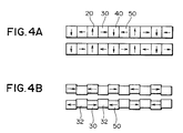
to generate such a periodical magnetic field are classified into two
types including, one, those of the Halbach type composed of permanent
magnet blocks 20, 30, 40, 50, ····· only as is schematically illustrated
in Figure 4A by a side view and, the other, those of the hybrid
type of which each array is composed of alternately arranged permanent
magnet blocks 30, 50, ····· and blocks of a soft magnetic material
or pole pieces 32, .
When high-speed electrons travelling in an electron accelerator
enter the periodical magnetic field between the arrays of magnet
blocks along the direction Z in Figure 3A, the electron takes a meandering
motion within the plane defined by the axes Z and X as is illustrated
in Figure 3C to emit a synchrotron radiation at each of the
meandering points as is reported by Halbach in Nuclear Instruments
and Methods, volume 187, page 109 (1981). The mode for the emission
of the synchrotron radiation is called either a wiggler mode or undulator
mode depending on the extent of meandering of the electrons. In
the wiggler mode emission, the radiations emitted at the respective
meandering points are superimposed to give a white synchrotron radiation
having an overall intensity 10 to 1000 times higher than the
radiation from a bending electromagnet. In the undulator mode radiation,
on the other hand, the radiations emitted from the respective
meandering points interfere each with the others to give a radiation
intensity 10 to 1000 times still higher than the wiggler mode radiations
relative to the fundamental radiation and higher harmonics
thereof. The differentiation between the wiggler mode radiations and
undulator mode radiations can be made in terms of the value of a
parameter K = 0.934 λm (m)·Bg (Tesla), where λm is the length of a
period and Bg is the peak value of the periodical magnetic field.
Namely, an undulator mode is obtained when the value of K is about
1 or smaller while the radiation is of the wiggler mode when K is otherwise.
For simplicity and convenience, the terms of undulator and insertion
device are used in the present invention to cover both of these
two modes. Further, in the following description, the "air gap direction"
means the direction from a magnet block in a first magnet block
array to a magnet block in a second magnet block array to oppose the
magnet block in the first array or, namely, the direction of the axis Y
in Figure 3A. The "axial direction" in the following description means
the direction of the orbit of electrons entering and traveling through
the periodical magnetic field between the magnet block arrays or,
namely, the direction of the axis Z in Figure 3A.
While, as is mentioned above, insertion devices are grossly classified
into those of the Halbach type and those of the hybrid type, no
great differences are found therebetween relative to the value and
distribution of the magnetic field. Generally speaking, however, the
overall weight of the magnet blocks can be smaller in the hybrid type
ones than in the Halbach type ones. In addition, the hybrid type insertion
devices were preferred in the early stage of development when
the manufacturing technology was at a low level not to give magnet
blocks with high accuracy relative to the value and angle of magnetization
in the magnet blocks while the requirements for the accuracy
of the above were lower in the hybrid type than in the Halbach type.
In recent years, however, a satisfactory magnetic field distribution
can be obtained in each of the insertion devices of the Halbach type
and hybrid type as a result of the improvement in the magnet manufacturing
technology and introduction of the method for recombination
of magnet block pairs. The displacement of the electron orbit
caused by the change in the air gap spacing is smaller in the Halbach
type than in the hybrid type due to the linearity held therein as compared
with the hybrid type with non-linearity of the soft-magnetic
pole pieces 32 to cause a relatively large displacement of the electron
orbit. The magnet block arrays illustrated in Figures 4A and 4B are
each conventional and called a planar undulator. Accordingly, choice
of either one of these types is not a matter of superiority or inferiority
but entirely depends on the particularly intended application of the
insertion device.
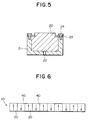
The most conventional method for fixing and assembling permanent
magnet blocks into an array is illustrated in Figure 5 by a cross
sectional view within the plane X - Y in Figure 3A. Thus, the magnet
block 20 is set in a rigid cassette 21 of a non-magnetic material and
fixed at the position either by using an adhesive or by a mechanical
means with presser plates 23 and screw bolts 24. The adhesive means
and mechanical means can be used in combination. Basically, the mechanical
means has higher reliability than adhesive bonding. The
magnetic field generated by the magnet block can be adjusted by
means of the adjustment hole 22 formed on the bottom or on the side
wall of the cassette 21. Since the cassette 21 can be prepared by mechanical
working using precision machine tools, the dimensional accuracy
of the cassette 21 is generally high as compared with the magnet
block 20. While the positioning accuracy of the magnet blocks 20
in the length-wise direction of the magnet block array is particularly
important, the positioning accuracy of the magnet blocks as required
can be obtained when the accuracy in the dimension of the cassette 21
and the screwing females for the screw bolts 23 is ensured. In view of
these advantages, the permanent magnet blocks 20 in the insertion
devices are usually fixed and assembled by using a cassette 21 in most
cases.
The above mentioned advantages obtained by using a cassette
for assembling a number of magnet blocks, however, are no longer
held when the period length (see Figure 3A) of the insertion device is
small with a consequently small thickness of each of the magnet
blocks. Suppose an insertion device of the Halbach type having a period
length of 10 mm, in which a single period is formed from four magnet
blocks, the thickness of each of the magnet blocks is only 2.5 mm.
Since the orbit form of the accelerated electrons in an insertion device
is greatly disturbed by the non-uniformity in the magnetic characteristics
of the individual permanent magnet blocks, it is essential to
minimize the errors in the remnant magnetization and angle error of
magnetization.When the thickness of the individual magnet blocks is
very small, nevertheless, the error in the magnetic characteristics is
unavoidably increased due to superimposition of several factors including
(1) an increased error in the dimensions of the magnet blocks
relative to the thickness, (2) a relative increase in the volume proportion
of the work-degradation layers caused by the mechanical working
of the magnet blocks, and (3) an increase in the error of the relative
thickness of the anti-corrosion surface layer. These errors are superimposed
onto the usual error in the magnetic properties as a consequence
of the powder metallurgical method for the preparation of
the permanent magnet blocks.
Other problems are caused also in respect of the accuracy of assembling
of the magnet blocks. Since it is a usual design of insertion
devices that the air gap spacing between the oppositely facing magnet
blocks in two arrays is selected to be about one half of the period
length, an insertion device of a period length of 10 mm is used with an
air gap spacing of about 5 mm. While the dimensional error in a permanent
magnet block prepared by mechanical working usually cannot
be much smaller than ± 0.05 mm, an error of ±2% is expected as
a possible maximum in the magnetic field in the air gap direction and
an integrated error of ± 4% is expected as a possible maximum in the
magnetic field in the axial direction. Accordingly, it is a requisite in
an insertion device having a period length of 10 mm that the error in
the dimensional accuracy of the permanent magnet blocks used therein
must not exceed one half or one third of that in an insertion device
having a conventional period length of 30 mm or larger.
The above mentioned high accuracy requirement in the dimensions
of the individual permanent magnet blocks is of course of little
significance unless being accompanied by the accuracy in assembling
of the magnet blocks into an array, which can be obtained only with a
difficulty. Assuming that the magnet blocks 20 of each 2.5 mm thickness
are assembled each by using a non-magnetic cassette 21, as is illustrated
in Figure 5, to form a Halbach type insertion device of 10
mm period length, for example, the width of the presser plate 23 must
be very small and the size of the screw bolts 24 must be correspondingly
so small because the thickness of the cassette 21 is also 2.5 mm
to hold a single magnet block 20. The screw bolt 24 thrusted into the
female in the cassette of 2.5 mm thickness cannot be larger than the
screw bolt of the M1 size in consideration of the difficulty in tapping of
the female thread and the size of the bolt head. Since the magnetic a-ttractive
force between the oppositely facing two permanent magnet
blocks in the two arrays is so strong that no very reliable assemblage
of the magnet blocks can be ensured with so feeble holding means
with tiny screw bolts 24. Although it is a seemingly possible way that
the permanent magnet blocks are directly fixed to a single base plate
instead of using separate cassettes, this way is not always practical
because gap spaces are sometimes formed between adjacent magnet
blocks due to the repulsive and rotational forces therebetween resulting
in inaccuracy in the positioning of the magnet blocks in the
length-wise direction of the magnet block array and consequently in
an increased error in the magnetic field distribution within the air
gap between the magnet block arrays.
In view of the above described problems and disadvantages in
the prior art in the preparation of a permanent magnet block assembly
for an insertion device having a period length not exceeding
10 mm, it is eagerly desired to develop a novel method for assemblage
of thin permanent magnet blocks apart from a mere improvement or
extension of the prior art methods.
One of the inventors, together with a co-inventor, previously
proposed, in Japanese Patent Kokai 8-255726, a magnet block assembly
for a short-period insertion device in which, as is schematically illustrated
in Figure 6, a plurality of magnet blocks are assembled in
an array and magnetized with high precision in alternately reversed
directions perpendicular to the length-wise direction of the array. The
magnet block arrays there proposed serve to realize an insertion device
of a period length not exceeding 20 mm. The characteristic advantages
obtained with this magnet block assembly include a decrease
in the requirement for the dimensional accuracy of the individual
magnet blocks because a single permanent magnet block here
covers a period or more in a conventional Halbach type insertion device
composed of four or more magnet blocks, a decreased problem due
to the working-degraded surface layer of the magnet blocks, applicability
of the conventional assembling method with non-magnetic
cassettes and a decrease in the assembling accuracy of the magnet
blocks as a consequence of the decrease in the number of the magnet
blocks. This method, however, has different difficulties relating to the
accuracy in the distribution of the magnetic field for the magnetization
of the magnet blocks and precision control of the positions of magnetization.
When magnetization of the magnet blocks is conducted consecutively
with pulses of magnetic field by using a magnetization head
having a coil, it is unavoidable that the electric resistance of the coil is
gradually increased as the temperature thereof is increased as a result
of heat generation therein to cause a shift in the distribution of
the pulsed magnetic field. Since the magnetization behavior of a rare
earth-based permanent magnet is non-linear relative to the magnetic
field for magnetization, the magnetization pattern of the permanent
magnet blocks is accordingly subject to a change thereby. This phenomenon
is particularly remarkable at the boundary of the N-pole
and the S-pole such as the boundary regions between the magnet
block 20 and the adjacent blocks 40. As a consequence, a disturbance
is caused in the distribution of magnetic field around the undulator
formed by assembling the permanent magnet blocks resulting in irregularity
of the electron orbit in the insertion device.
It is important in the magnetization of the magnet blocks of an
undulator to exactly control the positions of magnetization. Any irregularity
in the magnetization positions of the magnet blocks results
in an irregular distribution of the thickness of the individual magnet
units. It is necessary accordingly that positioning of the magnetization
head or relative positioning of the magnetization head and the
permanent magnet blocks has an accuracy with an error of ± 0.05 mm
or, desirably, ± 0.02 mm or smaller. This very strict requirement can
be satisfied only by the use of a precision-controlled driving system for
the magnetization head.
SUMMARY OF THE INVENTION
The present invention accordingly has an object to provide a novel
assembly of permanent magnet blocks for an insertion device of a
small period length not exceeding, for example, 10 mm, with which
the above described difficulties and disadvantages in the prior art can
be overcome by a simple and convenient means.
Thus, the magnet block assembly for an insertion device provided
by the present invention is an assembly which comprises:
BRIEF DESCRIPTION OF THE DRAWING
Figures 1A and 1B are each a schematic length-wise cross sectional
view of an elongated composite magnet block for an insertion
device of the Halbach type and hybrid type, respectively, according to
the invention.
Figure 2 is a schematic illustration of the magnetization system
for the magnetization of the composite magnet block for an insertion
device according to the invention.
Figure 3A is a schematic perspective view of the magnet block
arrays of the Halbach type for a conventional insertion device.
Figure 3B is a graph showing the sine-curved periodical magnetic
field generated in the air gap between the magnet block arrays
of Figure 3A.
Figure 3C is an illustration of the meandering electron orbit
travelling in the periodical magnetic field shown in Figure 3B.
Figure 4A shows the basic arrangement of the permanent magnet
block assemblies in an insertion device of the Halbach type.
Figure 4B shows the basic arrangement of the permanent magnet
blocks and soft-magnetic pole pieces in an insertion device of the
hybrid type.
Figure 5 is a cross sectional view of a permanent magnet block
held in a non-magnetic cassette to build up a planar undulator.
Figure 6 illustrates a magnetization pattern of permanent magnet
blocks in an undulator of a small period length.
DETAILED DESCRIPTION OF THE PREFERRED EMBODIMENTS
Although the principle of the above defined magnet block assemblies
of the invention for an insertion device is applicable to insertion
devices of any size, the invention is particularly useful and advantageous
when applied to an insertion device having a period
length not exceeding, for example, 10 mm.
Following is a detailed description, by making reference to the
accompanying drawing, of the magnet block assemblies of an insertion
device according to the invention.
Figures 1A and 1B each schematically illustrate a length-wise
cross sectional view of a composite magnet block of the planar undulator
1A and 1B of an insertion device of the Halbach type and hybrid
type, respectively.
Needless to say, the base block of a permanent magnet 10A or
10B as a base of the composite magnet block 1A,1B must have a sufficient
length corresponding to at least one period of the insertion device.
When the base magnet block 10A is anisotropically magnetic,
the axis of easy magnetization thereof should be in the air gap direction
or, namely, in the direction perpendicular to the travelling direction
of electrons, i.e. the axial direction, in the air gap as indicated by
the arrows written in the base magnet block 10A.
The magnet block 10A is prepared by mechanical working on a
magnet block by using a suitable machine tool with a grinding stone.
Namely, a magnet block is mechanically worked to form a plurality of
slits across the block, into which insert magnet pieces 3A, 5A, 7A,····
are to be inserted each between two adjacent cantilevered sectional
parts 2A, 4A, 6A, 8A,····, at regular intervals to define the period
length of the undulator. Each of the slits formed across the base magnet
block 10A has a thickness just to fit the insert magnet piece 3A,
5A, 7A, ···· to be inserted thereinto without any play and fixed
thereto, for example, by using an adhesive to complete the composite
magnet block 1A.
The base magnet block 10A with a plurality of slits is magnetized
in the cantilever sectional parts 2A, 4A, 6A, 8A, ···· in the alternately
reversed air gap direction as shown by the arrows written in
the respective parts while the insert magnet pieces 3A, 5A, 7A,····
are magnetized in the alternately reversed axial direction also shown
by the arrows written therein. The base magnet block 10A and the insert
magnet pieces 3A,5A,7A, ···· can be magnetized separately in
advance of the assemblage thereof into a composite magnet block 1A.
It is an alternative possible way that these members before magnetization
are assembled into the form of the composite magnet block 1A
and the members are magnetized at one time by means of a pulsed
magnetic field for magnetization. In this case, the two opposite cantilever
sectional parts on the opposite composite magnet blocks 1A, 1A
are magnetized in the same air gap direction while each of the insert
magnet pieces in one of the composite magnet block is magnetized in
the axial direction reverse to that of the insert magnet piece oppositely
facing the piece in the other composite magnet block.
It is of course an alternatively possible way relative to the direction
of magnetization of the respective magnet blocks in the composite
magnet block for an insertion device of the Halbach type that, though
less preferable, the cantilever sectional parts 2A, 4A, 6A, 8A, ···· are
magnetized each in the alternately reversed axial direction and the
insert magnet pieces 3A, 5A, 7A,···· are magnetized each in the alternately
reversed air gap direction. Following is the reason for the
less preference of this way of magnetization. When the directions of
magnetization of the magnet members are as shown in Figure 1A, the
repulsive force, which each of the insert magnet pieces 3A, 5A, 7A,···
magnetized in the axial direction receives from the cantilever
section- al parts 2A, 4A, 6A, 8A, ···· magnetized in the air gap
direction, is in such a direction that the insert magnet piece is pushed
against the bottom of the respective slit so that positioning of the
insert magnet pieces can be accomplished spontaneously even
without using any ad-hesives.
Figure 1B is a schematic length-wise cross sectional view of a
composite magnet block 1B for an insertion device of the hybrid type.
The base magnet block 10B here is conformal to the base magnet
block 10A illustrated in Figure 1A for the Halbach type with a plurality
of slits across the base magnet block 10B, into each of which an insert
pole piece of a soft magnetic material 3B, 5B, 7B,···· is inserted,
instead of the insert magnet pieces 3A, 5A, 7A, ···· in Figure 1A,
each between the cantilever sectional parts 2B, 4B, 6B, 8B,····. It is
preferable in this case that the cantilever sectional parts 2B, 4B, 6B,
8B,···· are magnetized each in the alternately reversed axial direction.
If the elongated magnet block 10B is anisotropically magnetic, it
is therefore preferable that the axis of easy magnetization thereof is
in the axial direction. In assemblage of two of such composite magnet
blocks 1B, 1B, the direction of magnetization of each of the cantilever
sectional parts is in the reversely axial direction relative to that of the
oppositely facing cantilever sectional part in the other composite
magnet block 1B.
As is understood from the above given description, the composite
magnet block 1A, 1B, being composed on the base of a single base
magnet block 10A, 10B instead of integration of a large number of
unit magnet blocks in the prior art, with insertion of the insert magnet
pieces or insert pole pieces inserted into the slits in the base magnet
block, is advantageously free from the dimensional error in the
axial direction due to superimposition of the thickness errors in the
individual unit magnet blocks in the prior art. This advantage is of
particular significance in an insertion device of which the period
length is small to be, for example, 10 mm or less.
In the following, a method for the magnetization of the above described
composite magnet block is described in detail by making reference
to Figure 2, in which the composite magnet block 1A is of the
Halbach type shown in Figure 1A.
Figure 2 is a schematic illustration of the system to generate a
pulsed magnetic field for the magnetization of the composite magnet
block 1A with a cross sectional view of the electromagnet 6 as the
magnetization head.
With the magnetization head 6 mounted on the composite magnet
block 1A as is shown in Figure 2, the electric charge accumulated
in the capacitor bank 7 is instantaneously discharged by means of the
thyristor switch 8 to cause a very large electric current through the
coil 9 of the electromagnet 6 so that a pulse-wise large magnetic field
indicated by the arrow B is generated to form a closed magnetic
circuit along the route from the N1 pole to the S1 pole of the electromagnet
6 through the cantilever sectional part 4A, insert magnet
piece 3A and cantilever sectional part 2A so that they are magnetized
in the direction indicated by the respective arrows. Since the distance
between the cantilever sectional parts 2A, 4A is invariable as determined
by the machining accuracy for the formation of the slit to
which the insert magnet piece 3A is inserted, the accuracy in the positioning
of the poles of the magnetization head is not under a strict requirement.
The magnetic field for the magnetization in this case
should be at least 15 kOe or, preferably, at least 18 kOe in order to accomplish
magnetization with good reliability. The pulse width of the
pulsed magnetic field should be at least 0.5 msecond or, preferably, at
least 2 mseconds. It is of course possible to accomplish magnetization
with a static magnetic field if an electromagnet and a DC power
source of such a large capacity are available disregarding the large
costs therefor.
Although, in the above described procedure for obtaining a composite
magnet block 1A, the magnetization is conducted after assemblage
of the base magnet block 10A with slits and the insert magnet
pieces 3A, 5A, 7A, ····· into the composite magnet block 1A, it is of
course optional that the base magnet block 10A with slits and the insert
magnet pieces 3A, 5A, 7A, ····· are separately magnetized in
advance and the thus magnetized members are assembled into a magnetized
composite magnet block 1A. In this latter case of pre-assemblage
magnetization, however, difficulties are unavoidable because,
in contrast to the former case of post-assemblage magnetization, each
of the insert magnet pieces 3A, 5A, 7A, ····· already magnetized
must be inserted under a repulsive or attractive force into one of the
slits in the base magnet block 10A magnetized in a direction perpendicular
to that of the insert magnet pieces 3A, 5A, 7A, ·····.
In the post-assemblage magnetization procedure illustrated in
Figure 2, the magnetic flux for magnetization forms a closed circuit
from the N1 pole of the magnetization head 6 to the S1 pole thereof
through the cantilever sectional part 4A, insert magnet piece 3A and
cantilever sectional part 2A as indicated by the arrows B1, B2 and B3,
respectively, so that the cantilever sectional parts 2A, 4A and the insert
magnet piece 3A can be magnetized at one time to give a magnetized
composite magnet block 1A in which the insert magnet pieces 3A,
5A, 7A, ······ can be spontaneously positioned by means of the repulsive
or attractive force with the cantilever sectional parts 2A, 4A, 6A,
8A ······.
The procedure for the magnetization of a hybrid type composite
magnet block 1B is substantially the same as that described above for
the Halbach type composite magnet block 1A.
The types of the permanent magnets forming the composite
magnet blocks 1A, 1B are not particularly limitative but anisotropically
magnetizable magnets prepared by a powder metallurgical process
from a rare earth metal-based alloy, such as the samarium-cobalt
alloys and rare earth-iron-boron alloys, are preferred in respect of the
strong magnetic field generated in the air gap between the composite
magnet blocks. When magnetization of the composite magnet block
1A or 1B is conducted by the post-assemblage magnetization procedure,
in particular, rare earth-iron-boron alloys are more preferable
due to easiness in the magnetization with a pulsed magnetic field.
The magnetized composite magnet blocks are held each in a holding
cassette without problems. The material to form the holding cassette
is not particularly limitative provided that the material is rigid and
non-magnetic including aluminum or aluminum-based alloys, stainless
steels and brass, of which stainless steels are preferred in respect
of their high sliding resistance. The soft magnetic material for the insert
pole pieces to be inserted into the slits in the base magnet block
10B for a hybrid type composite magnet block 1B is preferably iron or
an iron-based alloy such as a low-carbon steel SS400, SUY and iron-cobalt
alloys.
Two or more of the composite magnet blocks 1A or 1B are assembled
into an undulator of a small period length for an insertion device,
in which the number N of periods in a composite magnet block of 100
cm length can be as large as 100 assuming a period length of 10 mm
according to the invention. Since the theoretical intensity of radiation
emitted from an insertion device is proportional to the square of the
number N, a very strong synchrotron radiation can be emitted even in
a compact-size accelerator ring provided with an insertion device according
to the invention.
In the following, a particular embodiment of the present invention
is described in more detail by way of an Example.
Example.
Forty 40 mm by 40 mm wide and 20 mm thick sintered blocks of
a neodymium-iron-boron magnet alloy, of which the axis of easy magnetization
was in the direction of the 20 mm thickness, were each mechanically
worked with a grinding stone to form slits of each having a
thickness of 2 mm and depth of 15 mm at a regular interval of 2 mm in
parallel to one of the side surfaces to serve as base magnet blocks.
Separately, insert magnet pieces each having dimensions of 40
mm by 15 mm by 2 mm, of which the axis of easy magnetization was
in the direction of the 2 mm thickness, were prepared from the same
rare earth magnet alloy. These insert magnet pieces were inserted into
the slits in the base magnet blocks to be fitted thereto without play
to give forty composite magnet blocks.
On the other hand, a magnetization head was prepared which
had magnetization teeth of a five-period span so as to enable magnetization
of one of the above prepared composite magnet blocks at one
time. The yoke of the electromagnet for the magnetization head was
formed by laminating punch-formed 0.5 mm thick pure iron sheets
and provided with a coil. The magnetization teeth of the magnetization
head were brought into contact with the surface of the composite
magnet block and magnetization thereof was conducted by energizing
the coil with a capacitor bank of 4000 volts × 5000 µF capacity to generate
a pulsed magnetic field of at least 20 kOe as the peak value.
Each of the magnetized composite magnet blocks was inserted
into a holding cassette made from a non-magnetic stainless steel SUS
316L and 20 a group of the cassettes were linearly assembled to form
a 800 mm long elongated composite magnet block array in such a direction
that each of the insert magnet pieces in all of the composite
magnet blocks was within a plane across the array. A pair of the composite
magnet block arrays were positioned to oppose each the other
in such a way that each of the insert magnet pieces in one of the arrays
just opposed an insert magnet piece in the other array with an
air gap of 4 mm.
Distribution of the periodical magnetic field in the air gap of the
thus prepared 800 mm-long undulator of 100 periods was measured
by using a small-area Hall sensor to find that the peak values of the
peaks in the periodical magnetic field were very uniform with a variation
of ± 1.5% without undertaking any adjusting means.