EP0877341B1 - Vehicle rental system - Google Patents
Vehicle rental system Download PDFInfo
- Publication number
- EP0877341B1 EP0877341B1 EP98303634A EP98303634A EP0877341B1 EP 0877341 B1 EP0877341 B1 EP 0877341B1 EP 98303634 A EP98303634 A EP 98303634A EP 98303634 A EP98303634 A EP 98303634A EP 0877341 B1 EP0877341 B1 EP 0877341B1
- Authority
- EP
- European Patent Office
- Prior art keywords
- user
- vehicle
- key
- rental
- vehicles
- Prior art date
- Legal status (The legal status is an assumption and is not a legal conclusion. Google has not performed a legal analysis and makes no representation as to the accuracy of the status listed.)
- Expired - Lifetime
Links
Images


Classifications
-
- G—PHYSICS
- G07—CHECKING-DEVICES
- G07B—TICKET-ISSUING APPARATUS; FARE-REGISTERING APPARATUS; FRANKING APPARATUS
- G07B15/00—Arrangements or apparatus for collecting fares, tolls or entrance fees at one or more control points
-
- B—PERFORMING OPERATIONS; TRANSPORTING
- B62—LAND VEHICLES FOR TRAVELLING OTHERWISE THAN ON RAILS
- B62H—CYCLE STANDS; SUPPORTS OR HOLDERS FOR PARKING OR STORING CYCLES; APPLIANCES PREVENTING OR INDICATING UNAUTHORIZED USE OR THEFT OF CYCLES; LOCKS INTEGRAL WITH CYCLES; DEVICES FOR LEARNING TO RIDE CYCLES
- B62H3/00—Separate supports or holders for parking or storing cycles
- B62H3/08—Separate supports or holders for parking or storing cycles involving recesses or channelled rails for embracing the bottom part of a wheel
-
- B—PERFORMING OPERATIONS; TRANSPORTING
- B62—LAND VEHICLES FOR TRAVELLING OTHERWISE THAN ON RAILS
- B62H—CYCLE STANDS; SUPPORTS OR HOLDERS FOR PARKING OR STORING CYCLES; APPLIANCES PREVENTING OR INDICATING UNAUTHORIZED USE OR THEFT OF CYCLES; LOCKS INTEGRAL WITH CYCLES; DEVICES FOR LEARNING TO RIDE CYCLES
- B62H3/00—Separate supports or holders for parking or storing cycles
- B62H2003/005—Supports or holders associated with means for bike rental
Definitions
- the present invention relates to a vehicle rental system by which a vehicle is rented to a specified user.
- a distinguishing means such as a magnetic card which is in the possession of a member, is read by an evaluating means installed in the automobile, thereby judging whether use of the vehicle is valid or not, and if such use is possible, the door is unlocked and rental of the vehicle is permitted.
- the position of the concerned vehicle can be tracked by a central control apparatus via an automobile position discernment device. In this case, simplification of the rental procedure can be achieved, and since the position of the vehicle can be discerned, an advantage is attained in that the degree of freedom in returning the vehicle can be improved.
- a detection device is disposed in the vicinity of a key box containing a plurality of vehicle keys, for determining the usage conditions of the vehicle by specification of the key, together with whether the correct key exists or not. Further, by disposing a card reader, for reading data on a specialized card kept by the user, management of both the vehicle and the user is performed.
- the returned key can be specified by the detection device, it cannot be confirmed to the extent that the key is the very key which was rented out with respect to a given customer.
- a hotel reservation system a user's reservation is received, wherein the user's phone number or the like is registered as a code, and at the time of check-in, according to the code, a room card key is issued, and at check-out, by use of the returned card key, settling of accounts is conducted.
- a hotel reservation system a user's reservation is received, wherein the user's phone number or the like is registered as a code, and at the time of check-in, according to the code, a room card key is issued, and at check-out, by use of the returned card key, settling of accounts is conducted.
- a vehicle rental system it is necessary to prepare a plurality of vehicles within a parking area.
- a plurality of bicycles are parked, and typically by means of respectively equipped stands (i.e. kick stands), each bicycle is self-supported.
- a parking area in which a guide rail is arranged within the parking lot, wherein either the front or rear wheel can be connected to the guide rail.
- the width of the guide rail ordinarily cannot be set so as to accommodate all types of vehicles, in the case of a road racer type bicycles having narrow-width wheels, the vehicle body tends to slant, again hindering insertion and removal of adjacent bicycles.
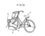
- This parking apparatus As a parking device in which this type of problem does not occur, there is known Japanese Laid-Open Patent Publication 8-104268, This parking apparatus, as shown in FIG. 24, is constructed by front wheel supporting walls 3 which grip both sides of a lower part of the front wheel 2 of a bicycle 1, and a front wheel locking device 5 connected to the front wheel supporting walls through a pipe arm 4, for gripping a frontal edge of the wheel 2.
- US-A-5,206643 discloses a system for managing a plurality of motor vehicles according to the precharacterising portion of claim 1.
- a general object of the present invention is to provide a vehicle rental system in which an electric vehicle desired by a user, together with a detachable battery, and a key for unlocking the electric vehicle can be rented extremely conveniently, without the intervention of other human operators.
- Another object of the present invention is to provide a vehicle rental system in which the key of the rented vehicle is freely and easily selected for within a range of use of a specified user, yet wherein sufficient security measures are also offered.
- Another object of the present invention is to provide a vehicle rental system in which it can be determined with certainty that the returned vehicle key is the specific key which was rented out by the user.
- Another object of the present invention is to provide a vehicle rental system in which insertion and removal from a parking area for two-wheeled vehicles which are to be rented can be easily accomplished, together with facilitating locking and unlocking operations at the parking area.
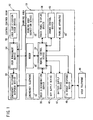
- FIG. 1 is an overall control block view of the vehicle rental system in accordance with an embodiment of the present invention.
- the vehicle rental system is equipped with a parking area 10 in which a plurality of electric vehicles are parked in a rentable condition, and a central control room 12 for managing the condition of the parking area 10 as well as vehicle users.
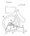
- FIG. 2 shows a two wheeled electric vehicle 14 which is an example of an electric vehicle which may be rented using the present rental system.
- the two wheeled electric vehicle 14 is equipped with an assist drive unit 16 which assists a driving power provided by a pedal 15, and a battery 18 for supplying electric power to the assist drive unit 16.
- the battery 18 is detachably accommodated in a battery case 20 attached to the front of a handle 19.
- the battery case 20 includes a lock 24 equipped with a lock mechanism 22.
- a C-channel coupling member 28 which is locked by a circle lock (discussed hereinafter) installed at the parking area 10 is disposed on a main frame 26 underneath the saddle 25.
- a circle lock 32 for preventing theft at an optional parking space for the two wheeled electric vehicle is disposed around the rear wheel 30.
- the lock mechanism 22 of the battery 18, the circle lock installed at the parking area 10, and the circle lock 32 on the rear wheel, can all be unlocked using the same key.
- the parking area 10 is equipped with a rental return control device 34 which controls overall rental processing as well as return processing of two wheeled electric vehicles at the parking area 10, and a user discrimination device 36 for discerning users from a user certificate such as a non-contact type IC card is connected to the rental return control device 34.
- a user discrimination device apart from a non-contact type IC card, a device in which a recorded fingerprint or eye pattern of the user is discriminated may also be used.
- a display device 38 having a selectable touch panel thereon (functioning as a selection means or a combined display/selection means) is connected to the rental return control device 34.
- the touch panel display device 38 displays selection information pertaining to selectable two wheeled electric vehicles, whereby the user selects a two wheeled electric vehicle 14 based on such selection information.
- a key supply device 40 holding a plurality of keys for the two wheeled electric vehicles 14 parked in the parking area and enabling selection of a key belonging to a desired two wheeled electric vehicle 14, and a battery supply device 42 holding a plurality of batteries 18 are connected to the rental return control device 34.
- a charge control device 43 for controlling charging of internal battery type two wheeled electric vehicles, a parking apparatus 44 for parking in a locked state a plurality of two wheeled electric vehicles, and a stock response device 48 responsive to requests from a user telephone 46 for performing a response of the in-stock state of a two wheeled electric vehicle at a given parking space 10 are also connected to the rental return control device 34.
- a parking area inspection device 50 made up of a CCD camera or the like for inspecting the condition of the parking area 10, and an emergency telephone 52 are disposed in the parking area 10.
- the central control room 12 includes a user management device 54, equipped with user registration functions, account settlement functions and management functions for the parking area 10, a user certification issuing device 56 for issuing a user certificate made up of a non-contact type IC card or the like, and an emergency telephone response device 58 for responding to requests from the emergency telephone 52 installed at the parking area 10.
- the user management device 54 and the rental return control device 34 at the parking area 10 perform transmittal and receipt of information via a modem 60.
- the key supply device 40 comprises a plurality of key boxes 64 disposed in a casing 62 and holding therein keys for the two wheeled electric vehicles 14.
- a magnet 72 for holding a receiving part 70 of a key door 68 in an attached and closed state is arranged, together with a sensor 74 made up of a microswitch or the like, for detecting a closed state of the key door 68.
- a key cylinder 76 with a key attached therein is arranged substantially in the center of the main body 66.
- the key cylinder 76 functions as a key discrimination means which is rotatable, only by a specified key, to positions for "rent out” and “returned” states.
- other devices which can specify a given key for example a CCD camera, laser scanner, or the like, can also by utilized as the key discrimination means.
- a solenoid 78 is disposed on top of the man body 66, and an retractable rod 80 which is driven thereby is also constructed within the main body 66.
- a coupling member 82 is disposed which couples with the rod 80 when the key door 68 is in a closed state.
- a recess 84 is formed for facilitating opening and closing.
- Light emitting elements 86, 88 made up of LED's or the like, and which indicate rented out and returned states, are disposed on top of the key boxes 64 which are constructed as described above.
- the key cylinder 76, solenoid 78 and light emitting elements 86, 88 are respectively connected to the rental return control device 34.
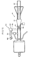
- FIG. 5 shows a battery 18 which is to be accommodated in the two wheeled electric vehicle 14 and the battery supply device 42.
- a battery 18 is constructed as a box-shape, having a handle 90 on an upper part thereof, wherein unillustrated electrodes are disposed on a bottom part thereof opposite from the handle 90.
- two projections 96 are provided, each which is formed by a flat coupling surface 92 which intersects with the side portion on a surface to one side of the handle 90, and a slanted surface 94 inclined with respect to the coupling surface 92 on a surface further separated from the handle 90.
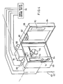
- a plurality of receptacles 100 for accommodating a plurality of batteries 18 constructed as described above are disposed within a main body 98 (see FIG. 3). Electrodes 104 which connect to a charging circuit 102 are disposed at the bottom of each receptacle 100, together with a sensor 106, such as a microswitch, for detecting that a battery 18 is accommodated therein.
- a lock mechanism 108 is arranged on an interior side of the receptacle 100, preventing withdrawal of the battery 18 by engagement with the projections 96 disposed on the side of the battery 18.
- a light emitting device 11 such as an LED showing the locked state of the battery 10
- a light emitting device 112 such as an LED displaying a charge state of the battery
- the charging circuit 102, sensor 106, lock mechanism 108 and light emitting elements 110, 112 are connected to the rental return control device 34. Further, the rental return control device 34 detects the charge condition of the battery 18 based on a signal from the charging circuit 102.
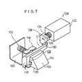
- the lock mechanism 108 which is disposed in the battery supply device 42, is constructed as shown in FIGS. 7 through 10. More specifically, the lock mechanism 108 comprises a claw member 114 for engaging one of the projections 96 disposed on a side of the battery 18, a holder 116 which supports the claw member 114, brackets 118 and 120 for supporting the holder 116, and a solenoid 112 which controls movement of the holder 116.
- the claw member 114 has an inclined surface 124 in sliding attachment with the slanted surface 94 (see FIG. 5) of the projection 96 at a time when the battery 18 is accommodated in the receptacle 110, and a coupling surface 126 which couples to the coupling surface 92 of the projection 96, and which is attached to an opening 128 of the holder 116.
- the holder 116 has a stop member 130 projecting from one side thereof, the holder 116 being formed by one surface to which the claw member 114 is attached and an opposite arcuately shaped side surface.
- a -shaped (C-channel) bracket 118 is disposed on the arcuately shaped surface.
- a substantially L-shaped bracket 120 engages the opening part 128 of the side surface of the holder 116 roughly perpendicularly to the stop member 130.
- a spring 132 is arranged between the surface of another end of the bracket 120 and the bracket 118 for maintaining the claw member 114 in the state shown by FIG. 8.
- a stopper 138 is attached to a rod 134 of the solenoid 122 making up the lock mechanism 108 through the spring 136. The stopper 138 engages the stop member 130 of the holder 116 in a condition in which the rod 134 is projected, for maintaining the claw member 114 in the state shown by FIG. 8.
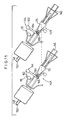
- a plurality of parking apparatuses 44 in which plural electric two wheeled vehicles 14 are parked, are disposed in the parking area 10.
- the parking apparatuses 44 are each equipped with a guide rail 140 for determining the position of a lateral direction of the electric two wheeled vehicle 14, a position determining mechanism 142 for determining a longitudinal position of the vehicle, a lock mechanism 144 for locking the electric two wheeled vehicle 14, and an outlet 145 for charging unillustrated internal battery type electric two wheel vehicles which are parked at a given parking apparatus 44. Further, determination of whether or not an internal battery type electric two wheel vehicle is connected to the outlet 145, and the charging state thereof, are control by a charge control device 43 under management of the rental return control device 34.
- the guide rail 140 is set at a fixed angular inclination with respect to a wall surface of the parking area 10. In this manner, by parking the two wheeled electric vehicles 10 at an inclination, the handles 19 of abutting parked two wheeled electric vehicles 14 do not interfere with each other, assuring a relatively large number of parking spaces.
- the position determining mechanism 142 is constructed from a first position determining frame 150 in which the front wheel 148 (e.g. 24 inch) of a large sized two wheel electric vehicle 14A abuts therewith (FIG.
- a vehicle sensor 158 is disposed for detecting the presence or absence of the two wheeled electric vehicle 14 (14A, 14B), as a detection of presence or absence of the front wheel.
- the vehicle sensor 158 is connected to the rental return control device 34.
- this position determining mechanism 143 has a position determining frame 151 formed by plural steps 149a-149c corresponding to hubs 147a-147c which differ in height and/or in their before and behind positions, adjusting to the size of the two wheeled electric vehicle 14.
- the lock mechanism is constructed from a support pillar 160 erected beside the guide rail 140, a pivot axis 162 disposed on an upper end of the support pillar 160, a pivot arm 164 having one end affixed to the pivot axis 162, and a circle lock 166 attached to the other end of the pivot arm 164.
- the circle lock 166 as shown in FIG. 15, by engaging a C-channel coupling member 28 on a main frame 26 of the two wheeled electric vehicle, prevents theft of the two wheeled electric vehicle, together with preventing toppling of the vehicle while it is parked. Further, when the main frame 26 is formed as a thin pipe, the circle lock 166 may also be directly coupled to the main frame 26.
- the height of the support pillar 160 making up the lock mechanism 144 is constructed so as be optionally variable, a wide range of types of two wheeled electric vehicles 14 can be accommodated thereby.
- the pivot 162 comprises a pivot axis 168 for pivotally connecting the pivot arm 164 to the support pillar 160, a swing arm 170 having a central part thereof axially supported on the pivot arm 164, a stop pin 172 embedded in the support pillar 160 for controlling the pivoting range of the pivot arm 164, and a holding pin 174 also embedded in the support pillar 160 for keeping the pivot arm 164 in the condition shown by the phantom lines in FIG. 16. Further, a roller 176 which abuts with the holding pin 174 upon pivoting of the pivot arm 164 is disposed on one end of the swing arm 170. The space between the other end of the swing arm 170 and the pivot arm 164 is connected by a spring 178.
- the vehicle rental system according to the present embodiment is constructed basically as described above. Next, an explanation shall be given concerning rental and return processing of two wheeled electric vehicles 14 used in the rental system.
- the parking apparatus 44 of the parking area 10 normally supplies a signal, relating to data of whether a two wheeled electric vehicle detected by a vehicle sensor 158 (see FIGS. 12-14) is available or not, to the rental return control device 34, and the rental return control device 34 converts such availability data to a voice signal indicating, for example, the type and number in stock of two wheeled electric vehicles, and supplies the same in real time to the stock response availability device 48.
- the user following the voice response from the stock availability response device 48, can determine the availability of a desired two wheeled electric vehicle 14. Further availability of stock can also be directly confirmed by an image of the interior of the parking area supplied, for example, by a cable television.
- user confirmation is performed by a user discrimination device 36.
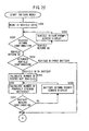
- User confirmation processing is performed in accordance with the flow chart shown in FIG. 17.
- the user brings his user certificate, such as a non-contact type IC card, into proximity to the user discrimination device 36 disposed at the parking area 10.
- the rental return control device 34 then reads in user data, such as the card ID number and user ID number, via the user discrimination apparatus (Step S1), and from such user data, a user ID number is extracted (Step S2).
- the extracted user ID number is transmitted to the user management device 54 over a modem 60, and by means of comparison with a registered user ID number, confirmation is performed as to whether the user is a valid legitimate user or not (Step S3).
- Step S4 abnormal processing is effected.
- Step S5 user data such as a security number pertaining to the user ID number, type of rental vehicles (range), validity period, and rental conditions, are read out from the user management device 54, and are transmitted to the rental return control device 34 over the modem 60 (Step S5).
- Step S6 it is confirmed whether the user is currently renting a two wheeled electric vehicle 14 or not. In this case, if a vehicle is currently being rented out, it is judged that the user intends to return the two wheeled electric vehicle 14, and "return mode" processing (to be described later) is effected (Step S7).
- Step S8 confirmation of user authority, indicating whether or not the user can currently use the system or not, is performed. If such authority is confirmed, next, it is determined whether the user certificate of the user is within a validity period (i.e. non-expired) (Step S9). Further, if the user is not authorized, or if the validity period has expired, abnormal processing is effected (Step S10). If the user possesses proper authority, and the validity period has not expired, a subsequent "rental mode" is effected (Step S11).
- a validity period i.e. non-expired
- Step S101 the user enters a security number using the touch panel display device 38 (Step S101).
- the rental return control device 34 initiates counting of the number of times that the security number is input (Step S102), together with comparing the input security number with a security number in the registered user data (Step S103). At this point, if the number of input times for the security number is greater than 3, the security number is regarded as incorrect and abnormal processing is effected (Step S105).
- vehicle selectability data based on data from the parking apparatus 44 is read in (Step S106) along with reading in the rental vehicle types (or range of types) from the user data (Step S107). More specifically, the parking apparatus 44 supplies data on availability of electric two wheeled vehicles (i.e. whether a given vehicle is present or not) as a signal from the vehicle sensor 158 (see FIGS. 11 and 12) to the rental return control device 34. In this case, the rental return control device 34, based on such availability data, generates data indicating whether the two wheeled electric vehicle 14 is currently being used, whether use thereof is possible within the range of rental vehicles for the given user, or whether the vehicle is unusable due to damage or the like. In addition, based on such data, usable vehicles are then displayed on the touch panel display device 38 (Step S108).
- the touch panel display device 38 On the touch panel display device 38, usable two wheeled electric vehicles 14 at the parking area 10 are displayed by means of pictures (photos) or the like, in order to enable understanding of color, size, saddle height, etc. In addition, information on the usage fee and usage times are also displayed. Based on such a display, the user selects a desired two wheeled electric vehicle 14 by manipulating the touch panel display device 38 (Step S109). The rental return control device 34 confirms whether the two wheeled electric vehicle selected by the user is usable or not (Step S110).
- the rental return control device 34 selects the vehicle number (Step S111) and reads in vehicle data corresponding to the vehicle number (Step S112).
- the rental return control device 34 outputs an unlocking signal to the key box 64 (see FIG. 4) which holds the key for the selected two wheeled electric vehicle 14.
- a solenoid 78 in the key box 64 in accordance with the unlocking signal, causes the rod 80 to be retracted from the coupling member 82 on the key door 68 (Step S113).
- the light emitting element 88 disposed on top of the key box 64 flashes, alerting the user that it is unlocked.
- the indication that the key box 64 holds a usable key, in place of being performed by a light emitting element 88 can likewise be performed by an audible signal or the like.
- Step S114 When the user opens the key door 68 of the key box 64 having the flashing light emitting element (Step S114), the sensor 74 is operated and the light emitting element 86 flashes, indicating that the key door 68 has been opened.
- the user rotates the key cylinder 76 to the "rented out” side, and pulls out the key (Step S116), at which point the light emitting element 86 assumes an illuminated state, together with informing the rental return control device 34 that the key has been removed (Step S117). In this case, it is confirmed by the rental return control device 34 that rental of the two wheeled electric vehicle 14 with a vehicle number corresponding to the concerned key has been initiated.
- Step S118 Once the user closes the key door 68 of the key box 64 (Step S118), the sensor 74 is operated and the light emitting elements 86, 88 are extinguished, together with informing the rental return control device 34 that the key door 68 has been closed (Step S119).
- the rental return control device 34 outputs a locking signal to the solenoid 78, wherein the rod 80 is lowered by the unlocking signal into engagement with the coupling member 82, and locking is performed (Step S120).
- the rental return control device 34 confirms the vehicle type of the rented two wheeled electric vehicle 14 from the vehicle number (Step S121). In this case, it is confirmed whether or not the selected two wheeled electric vehicle 14 requires a detachable battery 18, and if necessary, battery selectability data is read in (Step S122). Further, in the case of a two wheeled electric vehicle which does not use a detachable battery, the vehicle is directly charged via an outlet at the parking area 10, as shown in FIG. 3, and hence there is no need to select a battery.
- the battery selectability data includes battery availability data at the respective receptacles 100 of the battery supply device 42, and data pertaining to selectable batteries which is created by usability data based on charge condition. Further, battery availability can be confirmed by the sensor 106, shown in FIG. 6, whereas the charge condition can be confirmed by the charging circuit 102.
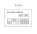
- the touch panel display device 38 displays rentable batteries, as shown in FIG. 21, based on the battery selectability data which was read-in (Step S123). More specifically, on the touch panel display device 38, in order to facilitate selection by the user, for example, fully charged rentable batteries 18, rented-out batteries 18, or non-fully charged batteries 18, are displayed in a state so that they can be distinguished from each other, for example using different colors. For example, by displaying uncharged states in red, half-charged states in yellow, three-fourths charged states in blue, and fully charged states in green, in the event that fully charged batteries are temporarily unavailable, batteries other than fully charged ones can still be rented and used for short distances.
- Step S124 the rental return control device 34 confirms whether or not the selected battery 18 is charged to a usable condition (Step S125), and if usable, the lock mechanism 108 of the corresponding receptacle 100 of the battery supply device 42 is unlocked (Step S126) together with illuminating the light emitting element 110.
- the battery supply device 42 is equipped with receptacles 100 capable of charging and maintaining a plurality of batteries which are greater in number than the number of rentable two wheeled electric vehicles at the parking area. Accordingly, if a user, for example from a condition in which all other two wheeled electric vehicles have been rented out, attempts to rent a two wheeled electric vehicle immediately after the return thereof, it is possible to quickly rent out an unused sufficiently charged battery 18 from the battery supply device 42. In this case, the user is not made to wait a long time in order for the battery 18 to be charged, permitting extremely efficient rental of two wheeled electric vehicles 14. Further, the number of batteries 18 can be set at under double that of the number of rentable two wheeled electric vehicles 14, however, it is also acceptable to simulate use conditions for setting an optimal number.
- the batteries 18 accommodated in the receptacles 100, as shown in FIG. 6, are locked by engagement of an engagement surface 92 of the projection 96 disposed on one side of the battery 18, with an engagement surface 126 of the claw member 114 making up the lock mechanism 108. Further, when in this condition, unillustrated electrodes on the bottom of the battery 18 contact electrodes 104 of the charging circuit 102, whereby charging is continually performed. In addition, the charge condition is detectable from the outside by means of light emitting elements 112.
- Step S126 when an unlocking signal is supplied to a specified receptacle 100 from the rental return control device 34, as shown in FIG. 7, the solenoid 122 is operated, the rod 134 is retracted and the stopper 138 becomes separated from the stop member 130 of the holder 116 (Step S126).
- the holder 116 inclines as shown in FIG. 9 through the claw member 114 of the lock mechanism 108, and by means of the projection 96 on the battery 18. Accordingly, the projection 96 overcomes the claw member 114 so that the battery 18 can be pulled out (Step S127).
- Step S1228 the solenoid 122 of the lock mechanism 108 is operated, and through the rod 134, the stopper 138 engages the stop member 130 of the holder 116, and the lock mechanism 108 once again becomes in a locked state, and moreover, the light emitting element 110 is extinguished.
- the rental return control device 34 writes in a flag, or the like, with respect to user data maintained in a register, indicating the vehicle number of the rented two-wheeled electric vehicle, a rental time schedule, and the fact that the vehicle is currently rented out (Step S130), transmitting the same to the user management device 54 over the modem 60 (Step S131). Further, the user ID number of the user of the concerned two wheeled electric vehicle, the rental start time, and so forth, are written in with respect to vehicle data maintained in a register (Step S132), and transmitted to the user management device 54 over the modem 60 (Step S133).
- the user After completing the rental processing as described above, the user utilizes the key which was taken out from the key supply device 40 and unlocks a given two wheeled electric vehicle 14 from the parking apparatus 44.
- the two wheeled electric vehicle 14 is locked in the parking apparatus 44 by the circle lock 116 disposed on an end of the pivot arm 164 making up the locking mechanism 144, which is arranged between adjacent two wheeled electric vehicles 14.
- the circle lock 166 is opened using the key and is taken out from the C-channel coupling member 28 of the main frame 26.
- the guide rails 140 are arranged to be slanted, no obstruction results with respect to the adjacent two wheeled electric vehicles 14 when unlocking the lock mechanism 144.
- the pivot arm 164 which is unlocked from the circle lock 166, as shown by FIG. 16, is pivoted about the pivot axis 168 of the support pillar 160, retreating to the position shown by the actual lines.
- the two wheeled electric vehicle 14 is taken out from the parking apparatus 44.
- the front and rear wheels of the two wheeled electric vehicle 14 are supported on the guide rail 140, and moreover, as shown by FIGS. 12 and 13, the front wheel 148 is still fixed in position by the position determining mechanism 142.
- the front wheel 48 is in a condition of abutment with the first position determining frame 150.
- the hub 154 of the wheel 152 thereof is in a condition of abutment with the second position determining frame 156. Accordingly, as shown in FIG.
- each of the two wheeled electric vehicles 14 is parked in a condition in which it is not inclined, or leaning over, due to being locked at the main frame 26.
- the user is not obstructed by adjacent two wheeled electric vehicles 14, and can easily enter in between such vehicles for performing the unlocking operation.
- a position determining frame 151 may be provided having a plurality of steps 149a - 149c thereon whose height and position are set in correspondence with the size of the two wheeled electric vehicles 14, wherein by regulating the position of the hub 147a -147c by the steps 149a - 149c, the position of the saddles 25 can also be set the same.
- the user after accommodating the battery 18 which has been pulled out from the battery supply device 42 in the battery case 20 of the two wheeled electric vehicle 14 removed as described above, and closing the lid 24, locks the lock mechanism 22 using the same key used to unlock the circle lock 166.
- the user mounts the two wheeled electric vehicle 14 having the battery 18 installed as described, and moves the vehicle to a desired location.
- the user at the parking area 10, similar to the case when the two wheeled electric vehicle 14 was rented out, first brings the user certificate into proximity with the user discrimination device 36.
- the rental return control device 34 reads in the user data, via the user discrimination device 36, and by comparison of the user ID extracted from the user data with a registered user ID, it is confirmed whether or not the user in question is a legitimate user.
- user data including the security number pertaining to the user ID, rental vehicle types (range), validity period, rental conditions, and so forth, are read out from the user management device 54, and based on the data of rental conditions, it is confirmed whether or not the user is currently renting out the two wheeled electric vehicle 14. In this case, because the vehicle is currently being rented out, it is judged that the user now intends to return the two wheeled electric vehicle 14, and "return mode" processing is effected.
- the rental return control device 34 reads in data including the vehicle number, user ID number, rental initiation time, rental return time, and the like (Step S201), and performs confirmation as to whether the two wheeled electric vehicle 14 relating to the vehicle number has been returned or not (Step S202).
- the touch panel display device 38 in the case that the two wheeled electric vehicle 14 has not been returned, displays a vehicle return prompt screen, prompting the user to return the vehicle (Step S203).
- the user returns the two wheeled electric vehicle 14 to a prescribed position in the parking apparatus 44. More specifically, the front wheel is engaged with respect to the guide rail 140, and next, after abutment of the front wheel of a two wheeled electric vehicle 14A against the first position determining frame 150, or abutment of the hub 154 of a two wheeled electric vehicle 14B against the second position determining frame 156, the circle lock 166 making up the lock mechanism 144 is locked into the C-channel coupling member 28 on the main frame 26. Further, when locked, the pivot arm is pivoted roughly 90° from the condition shown in FIG. 15, and because the roller 176 is fixed by being in a state of having surpassed the holding pin 174, the pivot arm 164 is maintained in a state shown by the phantom lines. Accordingly, the locking operation by the user is made easy.
- the sensor 158 disposed in the positioning determining device 142 detects the returned condition, and transmits a return detection signal to the rental return control device 34.
- the rental return control device 34 judges that the prescribed two wheeled electric vehicle 14 is now returned (Step S202), and performs confirmation of the type of returned vehicle based on the stock data (Step S204).
- Step S205 the number of currently rented out vehicles is calculated (Step S205), whereas, based on the number of batteries currently rented out as detected by the sensor 106 in the battery supply device 42, and the number of currently rented out vehicles, the proper number of batteries 18 to be kept in stock is calculated (Step S206). It is then confirmed whether on not the battery 18 has been returned or not (Step S207). In the case that the battery 18 has not been returned, the touch panel display device 38 displays a battery return prompt screen, prompting the user to return the battery (Step S208).
- the user takes out the battery 18 from the battery case 20, and places the battery into a receptacle 100 of the battery supply device 42.
- the inclined surface 94 of the projection 96 thereof press the inclined surface 24 of the claw member 114 of the lock mechanism 108.
- the claw member 114 is displaced with respect to the holder 116 in the direction of the arrow.
- the claw member 114 returns to the condition of FIG. 8 by the elastic force of spring 132. Further, return of the battery 18 is detected by the rental return control device 34.
- the rental return control device 34 In accordance with the vehicle number of the returned two wheel electric vehicle 14, outputs an unlocking signal to the corresponding key box 64 (see FIG. 4).
- the solenoid 78 of the key box 64 retracts the rod 80 from the coupling member 82 of the key door in accordance with the unlocking signal (Step S209). Based thereon, the key box 64 is unlocked. At this time, the light emitting element 88 on top of the key box 64 flashes, informing the user that the key box is unlocked.
- Step S210 When the user opens the key door 68 of the key box with the flashing light emitting element 88 (Step S210), the sensor 74 is operated and the light emitting element 86 flashes, signaling that the key door 68 is open (Step S211). The user inserts the key into the key cylinder 76 and rotates it to the "returned" side (Step S212), whereby the light emitting element 86 assumes an illuminated state, together with informing the rental return control device 34 that the key has been returned (Step S213).
- the rental return control device 34 compares the characteristic key data transmitted from the specified key cylinder 76 with the characteristic key data which is managed as user data of the user management device 54, and confirms that the concerned key is the specific key which was rented out.
- the cylinder 76 cannot be turned to the "returned" side, and therefore it can be determined that it is not a legitimate key.
- Step S214 When the user closes the key door 68 of the key box 64 (Step S214), the sensor 74 is operated and the light emitting elements 86, 88 are extinguished, together with informing the rental return control device 34 that the key door 68 has been closed (Step S215). Then, the rental return control device 34 supplies a locking signal to the solenoid 78, whereby in accordance with the locking signal, the rod 80 is lowered to engage the coupling member 82, and locking is performed (Step S216).
- the rental return control device 34 performs a clearing process, with respect to user data maintained in a register, to clear a flag indicating the vehicle number of the returned two wheeled electric vehicle 14 and that the vehicle is rented out, along with writing in the rental termination time (Step S217), and transmitting such information to the user management device 54 over the modem 60 (Step S218). Further, with respect to the vehicle data maintained in the register, a clearing process is performed to clear a flag indicating the user ID number and that the vehicle is rented out, and to write in the rental termination time (Step S219), transmitting such information to the user management device 54 over the modem 60 (Step S220).
- the use conditions of the user who performed rental of the two wheeled electric vehicle 14 are managed by the user management device 54 based on the user data. For example, the user conditions of the contracted user, with respect to each credit interval, are totaled, and the information of amount due is displayed via the touch panel display device 38, together with issuing usage details, performing processing of the amount due, and so forth.
- the batteries 18 are of the same form, from among the plural receptacles 100 disposed in the battery supply device 42, the battery can be returned optionally to any open receptacle 100.
- the battery can also be constructed to indicate receptacles to which the battery should be returned, corresponding to its battery type.
Landscapes
- Business, Economics & Management (AREA)
- Finance (AREA)
- Physics & Mathematics (AREA)
- General Physics & Mathematics (AREA)
- Engineering & Computer Science (AREA)
- Mechanical Engineering (AREA)
- Coin-Freed Apparatuses For Hiring Articles (AREA)
- Lock And Its Accessories (AREA)
- Management, Administration, Business Operations System, And Electronic Commerce (AREA)
Description
- The present invention relates to a vehicle rental system by which a vehicle is rented to a specified user.
- Numerous vehicle rental systems for rental of bicycles or other vehicles exist in accordance with prior techniques. For example, for an automobile rental system, the general practice is one in which a customer fills out necessary provisions onto documents at the rental company and receives a key, and after rental and use of a desired automobile for a predetermined time period, the vehicle is returned to the rental company. In this case, the handling of receipt and delivery of the rental contract and key, and accounting calculations necessary upon return of the vehicle, result in considerable complexity for the customer and rental company employees alike.
- Thus, for example, in a system disclosed by Japanese Laid-Open Patent Publication 6-68095, a distinguishing means, such as a magnetic card which is in the possession of a member, is read by an evaluating means installed in the automobile, thereby judging whether use of the vehicle is valid or not, and if such use is possible, the door is unlocked and rental of the vehicle is permitted. On the other hand, the position of the concerned vehicle can be tracked by a central control apparatus via an automobile position discernment device. In this case, simplification of the rental procedure can be achieved, and since the position of the vehicle can be discerned, an advantage is attained in that the degree of freedom in returning the vehicle can be improved.
- Further, in a system disclosed by Japanese Laid-Open Patent Publication 7-325959, in a rental station in which plural portable telephones are received, a card possessed by the user is employed, and a desired portable telephone is rented, wherein the rental fee therefor is calculated based on a summed value of use units which is internally stored within the portable telephone.
- However, according to such conventional techniques, a structure is not provided in which a certain type, or the like, of vehicle or portable phone, selectable by the user, can be easily and conveniently chosen.
- On the other hand, in Japanese Laid-Open Patent Publication 2-93796, an apparatus is disclosed enabling a battery owned by a user to be electrically charged for a fee.
- However, there is no discussion concerning key management. More specifically, as for a key which is rented together with the vehicle, in order to access the rented state of the vehicle, or for theft prevention, it is necessary to provide some management scheme therefore. For example, if a customer returns a key which is different from that which was rented out, subsequent customers cannot rent the vehicle belonging to that key. Further, there is a fear that the car in question could be used illegitimately, by intentionally returning a different key.
- As one type of key management system, for example as disclosed by Japanese Laid-Open Patent Publication 6-26249, a detection device is disposed in the vicinity of a key box containing a plurality of vehicle keys, for determining the usage conditions of the vehicle by specification of the key, together with whether the correct key exists or not. Further, by disposing a card reader, for reading data on a specialized card kept by the user, management of both the vehicle and the user is performed.
- However, even with this conventional technique, although the returned key can be specified by the detection device, it cannot be confirmed to the extent that the key is the very key which was rented out with respect to a given customer.
- Further, as a hotel reservation system, a user's reservation is received, wherein the user's phone number or the like is registered as a code, and at the time of check-in, according to the code, a room card key is issued, and at check-out, by use of the returned card key, settling of accounts is conducted. (See, Japanese Laid-Open Patent Publication 8-202776.)
- However, with this system, it is difficult for the user to freely select a room of choice, the rental procedures are troublesome, and furthermore, because the scope of such a rental is unrestricted, an unsuitability is indicated in which problems arise from the standpoint of security concerns.
- On the other hand, in a vehicle rental system, it is necessary to prepare a plurality of vehicles within a parking area. For example, at a parking lot near to a train station, a plurality of bicycles are parked, and typically by means of respectively equipped stands (i.e. kick stands), each bicycle is self-supported.
- At such a parking area, because plural bicycles are to be parked within the smallest possible space, the interval between adjacent bicycles becomes considerably narrowed. In this case, when the stand is on one side only, because the parked bicycles tend to slant, there is not only a fear of toppling over, but as the interval between adjacent bicycles becomes even narrower, unsuitability arises in that insertion and removal of bicycles becomes inconvenient.
- Thus, a parking area is known in which a guide rail is arranged within the parking lot, wherein either the front or rear wheel can be connected to the guide rail. In this case, it is possible that even bicycles without stands may be parked. However, because the width of the guide rail ordinarily cannot be set so as to accommodate all types of vehicles, in the case of a road racer type bicycles having narrow-width wheels, the vehicle body tends to slant, again hindering insertion and removal of adjacent bicycles.
- As a parking device in which this type of problem does not occur, there is known Japanese Laid-Open Patent Publication 8-104268, This parking apparatus, as shown in FIG. 24, is constructed by front
wheel supporting walls 3 which grip both sides of a lower part of thefront wheel 2 of abicycle 1, and a frontwheel locking device 5 connected to the front wheel supporting walls through apipe arm 4, for gripping a frontal edge of thewheel 2. - With a parking device constructed in this manner, because the
front wheel 2 of thebicycle 1 is gripped by both the frontwheel supporting walls 3 and thewheel locking device 5, irrespective of whether or not there is a stand, thebicycle 1 does not lean over, and accordingly an inconvenience in relation to insertion and removal of bicycles, caused by leaning, does not arise. - However, as shown by FIG. 25, when a plurality of bicycles are arranged side-by-side, the
handle 6b ofbicycle 1b, and thehandle 6a ofadjacent bicycle 1a or thehandle 6c ofbicycle 1c, interfere with each other, hindering the locking and unlocking operations of the frontwheel locking device 5 ofbicycle 1b. The problem is especially conspicuous in the event that thebicycle 1b is smaller in scale than the adjacent bicycles la and 1c. - US-A-5,206643 discloses a system for managing a plurality of motor vehicles according to the precharacterising portion of
claim 1. - A general object of the present invention is to provide a vehicle rental system in which an electric vehicle desired by a user, together with a detachable battery, and a key for unlocking the electric vehicle can be rented extremely conveniently, without the intervention of other human operators.
- Another object of the present invention is to provide a vehicle rental system in which the key of the rented vehicle is freely and easily selected for within a range of use of a specified user, yet wherein sufficient security measures are also offered.
- Still, another object of the present invention is to provide a vehicle rental system in which it can be determined with certainty that the returned vehicle key is the specific key which was rented out by the user.
- Yet, another object of the present invention is to provide a vehicle rental system in which insertion and removal from a parking area for two-wheeled vehicles which are to be rented can be easily accomplished, together with facilitating locking and unlocking operations at the parking area.
- According to the present invention there is provided a vehicle rental system according to
claim 1. - The above and other objects, features and advantages of the present invention will become more apparent from the following description when taken in conjunction with the accompanying drawings in which preferred embodiments of the present invention are shown by way of illustrative example.
- Embodiments of the present invention will now be described by way of example only, with reference to the accompanying drawings, in which: ,
- FIG. 1 is a structural block view of a vehicle rental system;
- FIG. 2 is an explanatory view of a two wheeled electric vehicle;
- FIG. 3 is a structural view of a parking area;
- FIG. 4 is a structural view of a key supply device;
- FIG. 5 is a structural view of a battery;
- FIG. 6 is a cross-sectional view of a battery supply device;
- FIG. 7 is a structural view of a locking mechanism in the battery supply device;
- FIG. 8 is a cross-sectional explanatory view showing a locked state of the locking mechanism in the battery supply device;
- FIG. 9 is a cross-sectional explanatory view showing an unlocked state of the locking mechanism in the battery supply device;
- FIG. 10. is a cross-sectional explanatory view showing a state when a battery is inserted into the battery supply apparatus;
- FIG. 11 is an explanatory plan view showing a parked state of a two wheeled electric vehicle in a parking area;
- FIG. 12. is an explanatory view showing the relation between a position determining mechanism and a large sized two wheeled electric vehicle;
- FIG. 13 is an explanatory view showing the relation between a position determining mechanism and a small sized two wheeled electric vehicle;
- FIG. 14 is another structural explanatory view of the position determining mechanism;
- FIG. 15 is a view explaining the relation between a lock mechanism and a two wheeled electric vehicle;
- FIG. 16 is a structural view of a rotating member making up the lock mechanism;
- FIG. 17 is a flow chart for performing confirmation processing of a user;
- FIG. 18 is a flow chart of a loaning mode;
- FIG. 19 is a flow chart of a loaning mode;
- FIG. 20 is a flow chart of a loaning mode;
- FIG. 21 is an explanatory view of battery rental information as displayed on a display device including a touch panel;
- FIG. 22 is a flow chart of a return mode;
- FIG. 23 is a flow chart of a return mode;
- FIG. 24 is an explanatory view of a parking apparatus according to a conventional technique; and
- FIG. 25 is an explanatory view of a parking state when the parking apparatus according to the conventional technique is under use.
- FIG. 1 is an overall control block view of the vehicle rental system in accordance with an embodiment of the present invention.
- The vehicle rental system is equipped with a
parking area 10 in which a plurality of electric vehicles are parked in a rentable condition, and acentral control room 12 for managing the condition of theparking area 10 as well as vehicle users. - Herein, FIG. 2 shows a two wheeled
electric vehicle 14 which is an example of an electric vehicle which may be rented using the present rental system. The two wheeledelectric vehicle 14 is equipped with anassist drive unit 16 which assists a driving power provided by apedal 15, and abattery 18 for supplying electric power to the assistdrive unit 16. Thebattery 18 is detachably accommodated in abattery case 20 attached to the front of ahandle 19. In order to prevent theft of the accommodated battery, thebattery case 20 includes alock 24 equipped with alock mechanism 22. Further, a C-channel coupling member 28 which is locked by a circle lock (discussed hereinafter) installed at theparking area 10 is disposed on amain frame 26 underneath thesaddle 25. Furthermore, acircle lock 32 for preventing theft at an optional parking space for the two wheeled electric vehicle is disposed around therear wheel 30. Thelock mechanism 22 of thebattery 18, the circle lock installed at theparking area 10, and thecircle lock 32 on the rear wheel, can all be unlocked using the same key. - The
parking area 10, as shown in FIGS. 1 and 3, is equipped with a rentalreturn control device 34 which controls overall rental processing as well as return processing of two wheeled electric vehicles at theparking area 10, and auser discrimination device 36 for discerning users from a user certificate such as a non-contact type IC card is connected to the rentalreturn control device 34. As the user discrimination device, apart from a non-contact type IC card, a device in which a recorded fingerprint or eye pattern of the user is discriminated may also be used. Adisplay device 38 having a selectable touch panel thereon (functioning as a selection means or a combined display/selection means) is connected to the rentalreturn control device 34. The touchpanel display device 38 displays selection information pertaining to selectable two wheeled electric vehicles, whereby the user selects a two wheeledelectric vehicle 14 based on such selection information. - A
key supply device 40 holding a plurality of keys for the two wheeledelectric vehicles 14 parked in the parking area and enabling selection of a key belonging to a desired two wheeledelectric vehicle 14, and abattery supply device 42 holding a plurality ofbatteries 18 are connected to the rentalreturn control device 34. Further, acharge control device 43 for controlling charging of internal battery type two wheeled electric vehicles, aparking apparatus 44 for parking in a locked state a plurality of two wheeled electric vehicles, and astock response device 48 responsive to requests from auser telephone 46 for performing a response of the in-stock state of a two wheeled electric vehicle at a givenparking space 10 are also connected to the rentalreturn control device 34. - A parking
area inspection device 50 made up of a CCD camera or the like for inspecting the condition of theparking area 10, and anemergency telephone 52 are disposed in theparking area 10. - The
central control room 12, as shown in FIG. 1, includes auser management device 54, equipped with user registration functions, account settlement functions and management functions for theparking area 10, a usercertification issuing device 56 for issuing a user certificate made up of a non-contact type IC card or the like, and an emergencytelephone response device 58 for responding to requests from theemergency telephone 52 installed at theparking area 10. Theuser management device 54 and the rentalreturn control device 34 at theparking area 10 perform transmittal and receipt of information via amodem 60. - Next, detailed explanation shall be given of specific features of the
key supply device 40, thebattery supply device 42 and theparking apparatus 44 disposed in theparking area 10. - The
key supply device 40, as shown in FIG. 4, comprises a plurality ofkey boxes 64 disposed in acasing 62 and holding therein keys for the two wheeledelectric vehicles 14. On a side of the interior of amain body 66, amagnet 72 for holding a receivingpart 70 of akey door 68 in an attached and closed state is arranged, together with asensor 74 made up of a microswitch or the like, for detecting a closed state of thekey door 68. Akey cylinder 76 with a key attached therein is arranged substantially in the center of themain body 66. - Further, the
key cylinder 76 functions as a key discrimination means which is rotatable, only by a specified key, to positions for "rent out" and "returned" states. In this case, in place of thecylinder 76, other devices which can specify a given key, for example a CCD camera, laser scanner, or the like, can also by utilized as the key discrimination means. - A
solenoid 78 is disposed on top of theman body 66, and anretractable rod 80 which is driven thereby is also constructed within themain body 66. On the other hand, on an upper part of thekey door 68 which is attached via hinges 81 to themain body 66, acoupling member 82 is disposed which couples with therod 80 when thekey door 68 is in a closed state. Further, on a side part of thekey door 68, arecess 84 is formed for facilitating opening and closing.Light emitting elements key boxes 64 which are constructed as described above. In addition, thekey cylinder 76,solenoid 78 andlight emitting elements return control device 34. - FIG. 5 shows a
battery 18 which is to be accommodated in the two wheeledelectric vehicle 14 and thebattery supply device 42. Such abattery 18 is constructed as a box-shape, having ahandle 90 on an upper part thereof, wherein unillustrated electrodes are disposed on a bottom part thereof opposite from thehandle 90. Further, on a side portion, twoprojections 96 are provided, each which is formed by aflat coupling surface 92 which intersects with the side portion on a surface to one side of thehandle 90, and aslanted surface 94 inclined with respect to thecoupling surface 92 on a surface further separated from thehandle 90. - In the
battery supply device 42, as shown in FIG. 6, a plurality ofreceptacles 100 for accommodating a plurality ofbatteries 18 constructed as described above are disposed within a main body 98 (see FIG. 3).Electrodes 104 which connect to acharging circuit 102 are disposed at the bottom of eachreceptacle 100, together with asensor 106, such as a microswitch, for detecting that abattery 18 is accommodated therein. In addition, alock mechanism 108 is arranged on an interior side of thereceptacle 100, preventing withdrawal of thebattery 18 by engagement with theprojections 96 disposed on the side of thebattery 18. Further, alight emitting device 11 such as an LED showing the locked state of thebattery 10, and alight emitting device 112 such as an LED displaying a charge state of the battery, are disposed at the opening of the receptacle. The chargingcircuit 102,sensor 106,lock mechanism 108 and light emittingelements return control device 34. Further, the rentalreturn control device 34 detects the charge condition of thebattery 18 based on a signal from the chargingcircuit 102. - The
lock mechanism 108, which is disposed in thebattery supply device 42, is constructed as shown in FIGS. 7 through 10. More specifically, thelock mechanism 108 comprises aclaw member 114 for engaging one of theprojections 96 disposed on a side of thebattery 18, aholder 116 which supports theclaw member 114,brackets holder 116, and asolenoid 112 which controls movement of theholder 116. - The
claw member 114 has aninclined surface 124 in sliding attachment with the slanted surface 94 (see FIG. 5) of theprojection 96 at a time when thebattery 18 is accommodated in thereceptacle 110, and acoupling surface 126 which couples to thecoupling surface 92 of theprojection 96, and which is attached to anopening 128 of theholder 116. Theholder 116 has astop member 130 projecting from one side thereof, theholder 116 being formed by one surface to which theclaw member 114 is attached and an opposite arcuately shaped side surface. A -shaped (C-channel)bracket 118 is disposed on the arcuately shaped surface. Furthermore, an end of a substantially L-shapedbracket 120 engages theopening part 128 of the side surface of theholder 116 roughly perpendicularly to thestop member 130. In addition, between the surface of another end of thebracket 120 and thebracket 118, aspring 132 is arranged for maintaining theclaw member 114 in the state shown by FIG. 8. On the other hand, astopper 138 is attached to arod 134 of thesolenoid 122 making up thelock mechanism 108 through thespring 136. Thestopper 138 engages thestop member 130 of theholder 116 in a condition in which therod 134 is projected, for maintaining theclaw member 114 in the state shown by FIG. 8. - A plurality of
parking apparatuses 44, in which plural electric twowheeled vehicles 14 are parked, are disposed in theparking area 10. The parking apparatuses 44, as shown in FIG. 3, are each equipped with aguide rail 140 for determining the position of a lateral direction of the electric twowheeled vehicle 14, aposition determining mechanism 142 for determining a longitudinal position of the vehicle, alock mechanism 144 for locking the electric twowheeled vehicle 14, and anoutlet 145 for charging unillustrated internal battery type electric two wheel vehicles which are parked at a givenparking apparatus 44. Further, determination of whether or not an internal battery type electric two wheel vehicle is connected to theoutlet 145, and the charging state thereof, are control by acharge control device 43 under management of the rentalreturn control device 34. - The
guide rail 140, as shown in FIG. 11, is set at a fixed angular inclination with respect to a wall surface of theparking area 10. In this manner, by parking the two wheeledelectric vehicles 10 at an inclination, thehandles 19 of abutting parked two wheeledelectric vehicles 14 do not interfere with each other, assuring a relatively large number of parking spaces. In order that the positions of thesaddles 25 of a plurality of parked two wheeled electric vehicles are set along a single straight line as shown by FIG. 11, theposition determining mechanism 142 is constructed from a firstposition determining frame 150 in which the front wheel 148 (e.g. 24 inch) of a large sized two wheelelectric vehicle 14A abuts therewith (FIG. 12), and a secondposition determining frame 156 in which thehub 154 of the front wheel 152 (e.g. 20 inch) of a small sized two wheelelectric vehicle 14B abuts therewith (FIG. 13). Further, in a space within alower guide rail 140 of thepositioning determining mechanism 142, avehicle sensor 158 is disposed for detecting the presence or absence of the two wheeled electric vehicle 14 (14A, 14B), as a detection of presence or absence of the front wheel. Thevehicle sensor 158 is connected to the rentalreturn control device 34. - Further, in place of the
position determining mechanism 142 shown in FIGS. 12 and 13, theposition determining mechanism 143 shown in FIG. 14 may also be used. More specifically, thisposition determining mechanism 143 has aposition determining frame 151 formed byplural steps 149a-149c corresponding tohubs 147a-147c which differ in height and/or in their before and behind positions, adjusting to the size of the two wheeledelectric vehicle 14. - The lock mechanism, as shown in FIGS. 3 and 15, is constructed from a
support pillar 160 erected beside theguide rail 140, apivot axis 162 disposed on an upper end of thesupport pillar 160, apivot arm 164 having one end affixed to thepivot axis 162, and acircle lock 166 attached to the other end of thepivot arm 164. Thecircle lock 166, as shown in FIG. 15, by engaging a C-channel coupling member 28 on amain frame 26 of the two wheeled electric vehicle, prevents theft of the two wheeled electric vehicle, together with preventing toppling of the vehicle while it is parked. Further, when themain frame 26 is formed as a thin pipe, thecircle lock 166 may also be directly coupled to themain frame 26. - Further, if the height of the
support pillar 160 making up thelock mechanism 144 is constructed so as be optionally variable, a wide range of types of two wheeledelectric vehicles 14 can be accommodated thereby. - The
pivot 162, as shown in FIG. 16, comprises apivot axis 168 for pivotally connecting thepivot arm 164 to thesupport pillar 160, aswing arm 170 having a central part thereof axially supported on thepivot arm 164, astop pin 172 embedded in thesupport pillar 160 for controlling the pivoting range of thepivot arm 164, and a holdingpin 174 also embedded in thesupport pillar 160 for keeping thepivot arm 164 in the condition shown by the phantom lines in FIG. 16. Further, aroller 176 which abuts with the holdingpin 174 upon pivoting of thepivot arm 164 is disposed on one end of theswing arm 170. The space between the other end of theswing arm 170 and thepivot arm 164 is connected by aspring 178. - The vehicle rental system according to the present embodiment is constructed basically as described above. Next, an explanation shall be given concerning rental and return processing of two wheeled
electric vehicles 14 used in the rental system. - When preceding to use the rental system, first, under control of the
user management device 54, using the usercertificate issuing device 56 in thecontrol room 12, information such as the contract user's address, name, rental car type (or range of types), bank account number for settlement of use fees, card ID number, user ID number, security number, and a valid period of use, and so forth, are registered, and a user certificate such as a non-contact type IC card is issued. Further, user information is registered in the "user list" of theuser management device 54. - Next, the user, now in possession of the user certificate, for example by the user telephone, calls to the stock
availability response device 48 of theparking area 10. In this case, theparking apparatus 44 of theparking area 10 normally supplies a signal, relating to data of whether a two wheeled electric vehicle detected by a vehicle sensor 158 (see FIGS. 12-14) is available or not, to the rentalreturn control device 34, and the rentalreturn control device 34 converts such availability data to a voice signal indicating, for example, the type and number in stock of two wheeled electric vehicles, and supplies the same in real time to the stockresponse availability device 48. Thus, the user, following the voice response from the stockavailability response device 48, can determine the availability of a desired two wheeledelectric vehicle 14. Further availability of stock can also be directly confirmed by an image of the interior of the parking area supplied, for example, by a cable television. - Once availability of stock has been confirmed, next, the user proceeds to rent out a desired two wheeled electric vehicle at the
parking area 10. In this case, first, user confirmation is performed by auser discrimination device 36. User confirmation processing is performed in accordance with the flow chart shown in FIG. 17. - More specifically, the user brings his user certificate, such as a non-contact type IC card, into proximity to the
user discrimination device 36 disposed at theparking area 10. The rentalreturn control device 34 then reads in user data, such as the card ID number and user ID number, via the user discrimination apparatus (Step S1), and from such user data, a user ID number is extracted (Step S2). The extracted user ID number, is transmitted to theuser management device 54 over amodem 60, and by means of comparison with a registered user ID number, confirmation is performed as to whether the user is a valid legitimate user or not (Step S3). At this point, in the case of an invalid user, abnormal processing is effected (Step S4). - One the other hand, when a valid user is confirmed, user data such as a security number pertaining to the user ID number, type of rental vehicles (range), validity period, and rental conditions, are read out from the
user management device 54, and are transmitted to the rentalreturn control device 34 over the modem 60 (Step S5). In addition, based on the data of rental conditions, it is confirmed whether the user is currently renting a two wheeledelectric vehicle 14 or not (Step S6). In this case, if a vehicle is currently being rented out, it is judged that the user intends to return the two wheeledelectric vehicle 14, and "return mode" processing (to be described later) is effected (Step S7). - When it is confirmed that a vehicle has not yet been rented, based on the user data, confirmation of user authority, indicating whether or not the user can currently use the system or not, is performed (Step S8). If such authority is confirmed, next, it is determined whether the user certificate of the user is within a validity period (i.e. non-expired) (Step S9). Further, if the user is not authorized, or if the validity period has expired, abnormal processing is effected (Step S10). If the user possesses proper authority, and the validity period has not expired, a subsequent "rental mode" is effected (Step S11).
- Accordingly, following the flow charts of FIGS. 18 through 20, "rental mode" processing shall now be explained.
- First, the user enters a security number using the touch panel display device 38 (Step S101). The rental
return control device 34 initiates counting of the number of times that the security number is input (Step S102), together with comparing the input security number with a security number in the registered user data (Step S103). At this point, if the number of input times for the security number is greater than 3, the security number is regarded as incorrect and abnormal processing is effected (Step S105). - On the other hand, in case of agreement of the security number, vehicle selectability data based on data from the
parking apparatus 44 is read in (Step S106) along with reading in the rental vehicle types (or range of types) from the user data (Step S107). More specifically, theparking apparatus 44 supplies data on availability of electric two wheeled vehicles (i.e. whether a given vehicle is present or not) as a signal from the vehicle sensor 158 (see FIGS. 11 and 12) to the rentalreturn control device 34. In this case, the rentalreturn control device 34, based on such availability data, generates data indicating whether the two wheeledelectric vehicle 14 is currently being used, whether use thereof is possible within the range of rental vehicles for the given user, or whether the vehicle is unusable due to damage or the like. In addition, based on such data, usable vehicles are then displayed on the touch panel display device 38 (Step S108). - On the touch
panel display device 38, usable two wheeledelectric vehicles 14 at theparking area 10 are displayed by means of pictures (photos) or the like, in order to enable understanding of color, size, saddle height, etc. In addition, information on the usage fee and usage times are also displayed. Based on such a display, the user selects a desired two wheeledelectric vehicle 14 by manipulating the touch panel display device 38 (Step S109). The rentalreturn control device 34 confirms whether the two wheeled electric vehicle selected by the user is usable or not (Step S110). - If the two wheeled
electric vehicle 14 selected by the user can be used, the rentalreturn control device 34 selects the vehicle number (Step S111) and reads in vehicle data corresponding to the vehicle number (Step S112). - Next, the rental
return control device 34, in accordance with the vehicle number, outputs an unlocking signal to the key box 64 (see FIG. 4) which holds the key for the selected two wheeledelectric vehicle 14. Asolenoid 78 in thekey box 64, in accordance with the unlocking signal, causes therod 80 to be retracted from thecoupling member 82 on the key door 68 (Step S113). As a result, only thekey box 64 which holds the key corresponding to the two wheeled electric vehicle selected by the user is unlocked. At this time, thelight emitting element 88 disposed on top of thekey box 64 flashes, alerting the user that it is unlocked. However, the indication that thekey box 64 holds a usable key, in place of being performed by alight emitting element 88, can likewise be performed by an audible signal or the like. - When the user opens the
key door 68 of thekey box 64 having the flashing light emitting element (Step S114), thesensor 74 is operated and thelight emitting element 86 flashes, indicating that thekey door 68 has been opened. The user rotates thekey cylinder 76 to the "rented out" side, and pulls out the key (Step S116), at which point thelight emitting element 86 assumes an illuminated state, together with informing the rentalreturn control device 34 that the key has been removed (Step S117). In this case, it is confirmed by the rentalreturn control device 34 that rental of the two wheeledelectric vehicle 14 with a vehicle number corresponding to the concerned key has been initiated. - Once the user closes the
key door 68 of the key box 64 (Step S118), thesensor 74 is operated and thelight emitting elements return control device 34 that thekey door 68 has been closed (Step S119). Thus, the rentalreturn control device 34 outputs a locking signal to thesolenoid 78, wherein therod 80 is lowered by the unlocking signal into engagement with thecoupling member 82, and locking is performed (Step S120). - Next, the rental
return control device 34 confirms the vehicle type of the rented two wheeledelectric vehicle 14 from the vehicle number (Step S121). In this case, it is confirmed whether or not the selected two wheeledelectric vehicle 14 requires adetachable battery 18, and if necessary, battery selectability data is read in (Step S122). Further, in the case of a two wheeled electric vehicle which does not use a detachable battery, the vehicle is directly charged via an outlet at theparking area 10, as shown in FIG. 3, and hence there is no need to select a battery. Herein, the battery selectability data includes battery availability data at therespective receptacles 100 of thebattery supply device 42, and data pertaining to selectable batteries which is created by usability data based on charge condition. Further, battery availability can be confirmed by thesensor 106, shown in FIG. 6, whereas the charge condition can be confirmed by the chargingcircuit 102. - The touch
panel display device 38 displays rentable batteries, as shown in FIG. 21, based on the battery selectability data which was read-in (Step S123). More specifically, on the touchpanel display device 38, in order to facilitate selection by the user, for example, fully chargedrentable batteries 18, rented-outbatteries 18, or non-fully chargedbatteries 18, are displayed in a state so that they can be distinguished from each other, for example using different colors. For example, by displaying uncharged states in red, half-charged states in yellow, three-fourths charged states in blue, and fully charged states in green, in the event that fully charged batteries are temporarily unavailable, batteries other than fully charged ones can still be rented and used for short distances. - Then the user, after selecting a desired usable battery number from among the displayed
batteries 18, selects a determined key (Step S124). In this case, the rentalreturn control device 34 confirms whether or not the selectedbattery 18 is charged to a usable condition (Step S125), and if usable, thelock mechanism 108 of thecorresponding receptacle 100 of thebattery supply device 42 is unlocked (Step S126) together with illuminating thelight emitting element 110. - Herein, the
battery supply device 42 is equipped withreceptacles 100 capable of charging and maintaining a plurality of batteries which are greater in number than the number of rentable two wheeled electric vehicles at the parking area. Accordingly, if a user, for example from a condition in which all other two wheeled electric vehicles have been rented out, attempts to rent a two wheeled electric vehicle immediately after the return thereof, it is possible to quickly rent out an unused sufficiently chargedbattery 18 from thebattery supply device 42. In this case, the user is not made to wait a long time in order for thebattery 18 to be charged, permitting extremely efficient rental of two wheeledelectric vehicles 14. Further, the number ofbatteries 18 can be set at under double that of the number of rentable two wheeledelectric vehicles 14, however, it is also acceptable to simulate use conditions for setting an optimal number. - The
batteries 18 accommodated in thereceptacles 100, as shown in FIG. 6, are locked by engagement of anengagement surface 92 of theprojection 96 disposed on one side of thebattery 18, with anengagement surface 126 of theclaw member 114 making up thelock mechanism 108. Further, when in this condition, unillustrated electrodes on the bottom of thebattery 18contact electrodes 104 of the chargingcircuit 102, whereby charging is continually performed. In addition, the charge condition is detectable from the outside by means of light emittingelements 112. - Then, when an unlocking signal is supplied to a specified
receptacle 100 from the rentalreturn control device 34, as shown in FIG. 7, thesolenoid 122 is operated, therod 134 is retracted and thestopper 138 becomes separated from thestop member 130 of the holder 116 (Step S126). In this condition, when the operator pulls out abattery 18 from thereceptacle 100, theholder 116 inclines as shown in FIG. 9 through theclaw member 114 of thelock mechanism 108, and by means of theprojection 96 on thebattery 18. Accordingly, theprojection 96 overcomes theclaw member 114 so that thebattery 18 can be pulled out (Step S127). - When the
battery 18 is withdrawn, thesensor 106 disposed on the bottom of thereceptacle 110 detects the absence of thebattery 18, and a detection signal thereof is transmitted to the rental return control device 34 (Step S128). In succession, thesolenoid 122 of thelock mechanism 108 is operated, and through therod 134, thestopper 138 engages thestop member 130 of theholder 116, and thelock mechanism 108 once again becomes in a locked state, and moreover, thelight emitting element 110 is extinguished (Step S129). - On the other hand, after completion of the above processing, the rental
return control device 34 writes in a flag, or the like, with respect to user data maintained in a register, indicating the vehicle number of the rented two-wheeled electric vehicle, a rental time schedule, and the fact that the vehicle is currently rented out (Step S130), transmitting the same to theuser management device 54 over the modem 60 (Step S131). Further, the user ID number of the user of the concerned two wheeled electric vehicle, the rental start time, and so forth, are written in with respect to vehicle data maintained in a register (Step S132), and transmitted to theuser management device 54 over the modem 60 (Step S133). - After completing the rental processing as described above, the user utilizes the key which was taken out from the
key supply device 40 and unlocks a given two wheeledelectric vehicle 14 from theparking apparatus 44. In this case, the two wheeledelectric vehicle 14, as shown in FIGS. 3 and 15, is locked in theparking apparatus 44 by thecircle lock 116 disposed on an end of thepivot arm 164 making up thelocking mechanism 144, which is arranged between adjacent two wheeledelectric vehicles 14. - Then, the
circle lock 166 is opened using the key and is taken out from the C-channel coupling member 28 of themain frame 26. In this case, as shown in FIG. 11, because theguide rails 140 are arranged to be slanted, no obstruction results with respect to the adjacent two wheeledelectric vehicles 14 when unlocking thelock mechanism 144. Thepivot arm 164 which is unlocked from thecircle lock 166, as shown by FIG. 16, is pivoted about thepivot axis 168 of thesupport pillar 160, retreating to the position shown by the actual lines. Further, when thepivot arm 164 is pivoted, accompanying the pivoting operation, aroller 176 arranged on an end of theswing arm 170 and which is axially attached to thepivot arm 164 surpasses thesupport pin 174 of thesupport pillar 160, while opposing the elastic force of thespring 178. At this time, the end of thepivot arm 164 abuts with thestop pin 172 and is halted. - After unlocking in the manner described above, the two wheeled
electric vehicle 14 is taken out from theparking apparatus 44. - At this point, as shown in FIG. 3, the front and rear wheels of the two wheeled
electric vehicle 14 are supported on theguide rail 140, and moreover, as shown by FIGS. 12 and 13, thefront wheel 148 is still fixed in position by theposition determining mechanism 142. In this case, for a two wheeledelectric vehicle 14A having a large sized front wheel 148 (see FIG. 12), thefront wheel 48 is in a condition of abutment with the firstposition determining frame 150. In contrast thereto, for a two wheeledelectric vehicle 14B having a small sizedfront wheel 152, thehub 154 of thewheel 152 thereof is in a condition of abutment with the secondposition determining frame 156. Accordingly, as shown in FIG. 11, by adjustment of the position of the secondposition determining frame 156, independent of the size of the two wheeledelectric vehicles saddle 25 with respect to the wall of theparking area 10, can be set the same (refer to the dotted line). - In this manner, because the position of
adjacent saddles 25 are set at the same position, even in the case that differently sized two wheeledelectric vehicles 14 are parked adjacently, a situation in which thehandlebars 19 interfere, resulting in inconvenience with respect to insertion and removal of two wheeledelectric vehicles 14, can be avoided. - Further, each of the two wheeled
electric vehicles 14 is parked in a condition in which it is not inclined, or leaning over, due to being locked at themain frame 26. As a result, the user is not obstructed by adjacent two wheeledelectric vehicles 14, and can easily enter in between such vehicles for performing the unlocking operation. - Further, as shown in FIG. 14, a
position determining frame 151 may be provided having a plurality ofsteps 149a - 149c thereon whose height and position are set in correspondence with the size of the two wheeledelectric vehicles 14, wherein by regulating the position of thehub 147a -147c by thesteps 149a - 149c, the position of thesaddles 25 can also be set the same. - The user, after accommodating the
battery 18 which has been pulled out from thebattery supply device 42 in thebattery case 20 of the two wheeledelectric vehicle 14 removed as described above, and closing thelid 24, locks thelock mechanism 22 using the same key used to unlock thecircle lock 166. The user then mounts the two wheeledelectric vehicle 14 having thebattery 18 installed as described, and moves the vehicle to a desired location. - Next, processing upon return of the used two wheeled
electric vehicle 14 shall be explained. The user, at theparking area 10, similar to the case when the two wheeledelectric vehicle 14 was rented out, first brings the user certificate into proximity with theuser discrimination device 36. The rentalreturn control device 34 reads in the user data, via theuser discrimination device 36, and by comparison of the user ID extracted from the user data with a registered user ID, it is confirmed whether or not the user in question is a legitimate user. When a legitimate user is confirmed, user data including the security number pertaining to the user ID, rental vehicle types (range), validity period, rental conditions, and so forth, are read out from theuser management device 54, and based on the data of rental conditions, it is confirmed whether or not the user is currently renting out the two wheeledelectric vehicle 14. In this case, because the vehicle is currently being rented out, it is judged that the user now intends to return the two wheeledelectric vehicle 14, and "return mode" processing is effected. - Next, such "return mode" processing shall be explained following the flow charts shown in FIGS. 19 and 20.
- First, the rental
return control device 34 reads in data including the vehicle number, user ID number, rental initiation time, rental return time, and the like (Step S201), and performs confirmation as to whether the two wheeledelectric vehicle 14 relating to the vehicle number has been returned or not (Step S202). The touchpanel display device 38, in the case that the two wheeledelectric vehicle 14 has not been returned, displays a vehicle return prompt screen, prompting the user to return the vehicle (Step S203). - Then, the user returns the two wheeled
electric vehicle 14 to a prescribed position in theparking apparatus 44. More specifically, the front wheel is engaged with respect to theguide rail 140, and next, after abutment of the front wheel of a two wheeledelectric vehicle 14A against the firstposition determining frame 150, or abutment of thehub 154 of a two wheeledelectric vehicle 14B against the secondposition determining frame 156, thecircle lock 166 making up thelock mechanism 144 is locked into the C-channel coupling member 28 on themain frame 26. Further, when locked, the pivot arm is pivoted roughly 90° from the condition shown in FIG. 15, and because theroller 176 is fixed by being in a state of having surpassed the holdingpin 174, thepivot arm 164 is maintained in a state shown by the phantom lines. Accordingly, the locking operation by the user is made easy. - When the two wheeled
electric vehicle 14 is returned to aprescribed parking apparatus 44 as described above, thesensor 158 disposed in thepositioning determining device 142 detects the returned condition, and transmits a return detection signal to the rentalreturn control device 34. As a result, the rentalreturn control device 34 judges that the prescribed two wheeledelectric vehicle 14 is now returned (Step S202), and performs confirmation of the type of returned vehicle based on the stock data (Step S204). - At this point, in the event that the returned vehicle is a two wheeled
electric vehicle 14 which has adetachable battery 18, the number of currently rented out vehicles is calculated (Step S205), whereas, based on the number of batteries currently rented out as detected by thesensor 106 in thebattery supply device 42, and the number of currently rented out vehicles, the proper number ofbatteries 18 to be kept in stock is calculated (Step S206). It is then confirmed whether on not thebattery 18 has been returned or not (Step S207). In the case that thebattery 18 has not been returned, the touchpanel display device 38 displays a battery return prompt screen, prompting the user to return the battery (Step S208). - Then, the user takes out the
battery 18 from thebattery case 20, and places the battery into areceptacle 100 of thebattery supply device 42. At this point, when thebattery 18 is inserted, theinclined surface 94 of theprojection 96 thereof, press theinclined surface 24 of theclaw member 114 of thelock mechanism 108. In this case, as shown in FIG. 10, theclaw member 114 is displaced with respect to theholder 116 in the direction of the arrow. In addition, when placement therein of the battery has been completed, theclaw member 114 returns to the condition of FIG. 8 by the elastic force ofspring 132. Further, return of thebattery 18 is detected by the rentalreturn control device 34. - After return of both the two wheeled
electric vehicle 14 and thebattery 18, the user returns the key. In this case, the rentalreturn control device 34, in accordance with the vehicle number of the returned two wheelelectric vehicle 14, outputs an unlocking signal to the corresponding key box 64 (see FIG. 4). Thesolenoid 78 of thekey box 64 retracts therod 80 from thecoupling member 82 of the key door in accordance with the unlocking signal (Step S209). Based thereon, thekey box 64 is unlocked. At this time, thelight emitting element 88 on top of thekey box 64 flashes, informing the user that the key box is unlocked. - When the user opens the
key door 68 of the key box with the flashing light emitting element 88 (Step S210), thesensor 74 is operated and thelight emitting element 86 flashes, signaling that thekey door 68 is open (Step S211). The user inserts the key into thekey cylinder 76 and rotates it to the "returned" side (Step S212), whereby thelight emitting element 86 assumes an illuminated state, together with informing the rentalreturn control device 34 that the key has been returned (Step S213). - The rental
return control device 34 compares the characteristic key data transmitted from the specifiedkey cylinder 76 with the characteristic key data which is managed as user data of theuser management device 54, and confirms that the concerned key is the specific key which was rented out. - Further, when the key which has been inserted into the
key cylinder 76 by the user is different from the key which was rented out, thecylinder 76 cannot be turned to the "returned" side, and therefore it can be determined that it is not a legitimate key. - When the user closes the
key door 68 of the key box 64 (Step S214), thesensor 74 is operated and thelight emitting elements return control device 34 that thekey door 68 has been closed (Step S215). Then, the rentalreturn control device 34 supplies a locking signal to thesolenoid 78, whereby in accordance with the locking signal, therod 80 is lowered to engage thecoupling member 82, and locking is performed (Step S216). - On the other hand, the rental
return control device 34 performs a clearing process, with respect to user data maintained in a register, to clear a flag indicating the vehicle number of the returned two wheeledelectric vehicle 14 and that the vehicle is rented out, along with writing in the rental termination time (Step S217), and transmitting such information to theuser management device 54 over the modem 60 (Step S218). Further, with respect to the vehicle data maintained in the register, a clearing process is performed to clear a flag indicating the user ID number and that the vehicle is rented out, and to write in the rental termination time (Step S219), transmitting such information to theuser management device 54 over the modem 60 (Step S220). - By performing the above steps, return processing of the two wheeled electric vehicle is completed. Further, the use conditions of the user who performed rental of the two wheeled
electric vehicle 14 are managed by theuser management device 54 based on the user data. For example, the user conditions of the contracted user, with respect to each credit interval, are totaled, and the information of amount due is displayed via the touchpanel display device 38, together with issuing usage details, performing processing of the amount due, and so forth. - Further, in the above described embodiment, because the
batteries 18 are of the same form, from among theplural receptacles 100 disposed in thebattery supply device 42, the battery can be returned optionally to anyopen receptacle 100. However, in the case of plural different types ofbatteries 18, it can also be constructed to indicate receptacles to which the battery should be returned, corresponding to its battery type. - In this case, if
receptacles 100 apart from those in which the battery can be returned are kept in a locked state, an inconvenience can be avoided in which a different type of battery is mistakenly placed into a receptacle to which it does not correspond.
Claims (18)
- A vehicle rental system comprising:a parking apparatus (44) in which a plurality of rentable vehicles (14) are locked and parked;a user discriminating device (36) for discerning a user who shall use said vehicles;a display device (38) for displaying selection information concerning selectable vehicles;a key supply device (40) which maintains keys for unlocking said vehicles, said keys being maintained by said key supply device (40) in a locked condition, and which enables selection of a given key for the vehicles to be used based on the display of said display device;a rental return control device (34) for controlling said parking apparatus, said user discriminating device, said display device, and said key supply device, and for performing rental processing and return processing of said vehicles; anda user management device (54) for managing use conditions of the user who uses said vehicle,characterised in that the vehicles are electric vehicles, the vehicle rental system comprising a battery supply device (42) which is also controlled by said rental return control device (34) and which maintains detachable batteries (18) for said electric vehicles and which charges said batteries, and wherein said key supply device (40) comprises a key discriminating means (76) for discerning the given key by means of operation thereof which can only be carried out by a specified one of said keys.
- The vehicle rental system according to claim 1, further comprising a user certification issuing device (56) for issuing a user certificate to said user to use said electric vehicle, wherein said user discriminating device discerns the user information which is recorded on said user certificate.
- The vehicle rental system according to claim 1, further comprising a stock answering device (48) having therein stock information of electric vehicles capable of rental at said parking apparatus, and for answering a request from the user.
- The vehicle rental system according to claim 1, further comprising an emergency telephone answering device (58) for answering a request from a user in the event of an emergency at said parking apparatus.
- The vehicle rental system according to claim 1, further comprising a parking area inspection device (50) for inspecting the condition of a parking area (10) at which a plurality of rentable electric vehicles are parked.
- The vehicle rental system according to claim 1,
wherein said display device further comprises a touch panel display device (38) for indicating a desired motor vehicle from displayed selection information. - The vehicle rental system according to claim 1, said electric vehicles comprising two wheeled vehicles accommodating detachable batteries, wherein said parking apparatus enables a plurality of said two wheeled vehicles to be arrayed alongside each other in a locked state, further comprising
a position determining mechanism (142) for deciding a position of a front wheel of said two wheeled vehicle, taking a saddle position thereof as a standard;
a locking device (166) coupled to a coupling member (28) disposed on a vehicle body frame supporting said saddle; and
a locking device moving mechanism (162) disposed on a saddle side portion of the parked two wheeled vehicle, for moving said locking device between said two wheeled vehicle saddle side portion and said coupling member. - The vehicle rental system according to claim 7, said positioning determining mechanism further comprising:a first position determining frame (150) for deciding a position by abutment of a frontal edge part of the front wheel of a large scale two-wheeled vehicle; anda second position determining frame (156) for deciding a position by abutment of a front wheel hub of a small scale two wheeled vehicle,wherein the saddle position of said large scale two wheeled vehicle and said small scale two wheeled vehicle are set along a straight line.
- The vehicle rental system according to claim 7, said positioning determining mechanism further comprising a stepped position determining frame (151) having a plurality of steps which are set in correspondence with a position of front wheel hubs of differently sized two wheeled vehicle, wherein by abutment of said front wheel hubs with said steps, the saddle positions of differently sized two wheeled vehicles are set substantially along a straight line.
- The vehicle rental system according to claim 7, wherein said locking device moving mechanism comprises:a support post (160) disposed at a saddle side of said two wheeled vehicle;a pivot arm (164) having one end thereof axially supported on an upper end of said support post, said locking device begin disposed on another end thereof, and said pivot arm being pivotally disposed between said coupling member and said saddle side.
- The vehicle rental system according to claim 10, further comprising a support (170, 174) disposed on an end part of said axially supported pivot arm, for support and regulating the pivotal movement of said pivot arm when said locking device is in a state of abutment with said coupling member.
- The vehicle rental system according to claim 7, wherein the key for unlocking said locking device also unlocks another locking device which is attached to said two wheeled vehicle.
- The vehicle rental system according to claim 1, wherein said user discriminating device discerns user information which is recorded on an IC card.
- The vehicle rental system according to claim 1, wherein said key supply device comprising a plurality of key boxes (64) holding respective keys in a locked condition.
- The vehicle rental system according to claim 14, wherein each of said key boxes comprises a locking mechanism (78, 80) which is locked and unlocked under the control of said rental return control device.
- The vehicle rental system according to claim 14, wherein each of said key boxes comprises a display device (86, 88) which displays whether the key is in a rented or a returned state.
- The vehicle rental system according to claim 15, wherein said rental return control device relates and stores characteristic key data of the key which is rented out by said user with user data of said user discerned by said user discriminating means, compares characteristic key data discriminated by said key discriminating device at the time of return with the characteristic key data of the user recorded at the time of rental, and based on a comparison result, determines whether the returned key is the same as the rented key.
- The vehicle rental system according to claim 1, wherein said rental return control device controls said battery supply device for enabling rental only of usable charged batteries.
Applications Claiming Priority (12)
| Application Number | Priority Date | Filing Date | Title |
|---|---|---|---|
| JP11956097 | 1997-05-09 | ||
| JP11956997 | 1997-05-09 | ||
| JP9119578A JPH10306631A (en) | 1997-05-09 | 1997-05-09 | Key control system |
| JP11956097A JP3839550B2 (en) | 1997-05-09 | 1997-05-09 | Bicycle parking equipment |
| JP119560/97 | 1997-05-09 | ||
| JP11954397A JP3596579B2 (en) | 1997-05-09 | 1997-05-09 | Electric vehicle rental system |
| JP11956997A JPH10306630A (en) | 1997-05-09 | 1997-05-09 | Key control system |
| JP119578/97 | 1997-05-09 | ||
| JP119569/97 | 1997-05-09 | ||
| JP11957897 | 1997-05-09 | ||
| JP119543/97 | 1997-05-09 | ||
| JP11954397 | 1997-05-09 |
Publications (3)
| Publication Number | Publication Date |
|---|---|
| EP0877341A2 EP0877341A2 (en) | 1998-11-11 |
| EP0877341A3 EP0877341A3 (en) | 2001-10-24 |
| EP0877341B1 true EP0877341B1 (en) | 2007-02-07 |
Family
ID=27470602
Family Applications (1)
| Application Number | Title | Priority Date | Filing Date |
|---|---|---|---|
| EP98303634A Expired - Lifetime EP0877341B1 (en) | 1997-05-09 | 1998-05-08 | Vehicle rental system |
Country Status (2)
| Country | Link |
|---|---|
| US (1) | US6157315A (en) |
| EP (1) | EP0877341B1 (en) |
Families Citing this family (67)
| Publication number | Priority date | Publication date | Assignee | Title |
|---|---|---|---|---|
| EP1006490A3 (en) * | 1998-12-01 | 2001-08-22 | Volkswagen Aktiengesellschaft | Vehicle hiring system |
| JP2000293795A (en) | 1999-04-05 | 2000-10-20 | Honda Motor Co Ltd | Device for managing entering and leaving parking lot of shared vehicle |
| JP2000320210A (en) | 1999-05-07 | 2000-11-21 | Honda Motor Co Ltd | Vehicle and returning and collecting controller therefor |
| US6941197B1 (en) | 1999-07-07 | 2005-09-06 | The Regents Of The University Of California | Vehicle sharing system and method with vehicle parameter tracking |
| US6850898B1 (en) | 1999-07-07 | 2005-02-01 | The Regents Of The University Of California | Vehicle sharing system and method for allocating vehicles based on state of charge |
| US7181409B1 (en) * | 1999-07-07 | 2007-02-20 | The Regents Of The University Of California | Shared vehicle system and method involving reserving vehicles with highest states of charge |
| JP2001076288A (en) * | 1999-07-07 | 2001-03-23 | Honda Motor Co Ltd | Vehicle sharing system provided with assigning function based on trip information, and its method |
| US6947881B1 (en) | 1999-07-07 | 2005-09-20 | Honda Giken Kogyo Kabushiki Kaisha | Shared vehicle system and method with vehicle relocation |
| US6975997B1 (en) | 1999-07-07 | 2005-12-13 | Honda Giken Kogyo Kabushiki Kaisha | Method for efficient vehicle allocation in vehicle sharing system |
| US6850153B1 (en) | 1999-07-07 | 2005-02-01 | The Regents Of The University Of California | Vehicle sharing system and method for controlling or securing vehicle access and/or enablement |
| JP2002133510A (en) * | 2000-07-27 | 2002-05-10 | Sony Corp | Moving body rental system, moving body control system, moving body system, moving body controller, moving body rental method, moving body control method, and recording medium |
| JP2002063513A (en) * | 2000-08-23 | 2002-02-28 | Nec Corp | Method and system for rental car reservation, and recording medium with rental car reserving program recorded thereon |
| EP1342187A4 (en) * | 2000-10-27 | 2006-07-05 | Vanguard Trademark Holdings S | Method for completing and storing an electronic rental agreement |
| JP2002196988A (en) * | 2000-12-27 | 2002-07-12 | Sharp Corp | Storage medium |
| US20020147693A1 (en) * | 2001-04-05 | 2002-10-10 | International Business Machines Corporation | Method and system for dynamic accounting of service and equipment usage |
| JP2003016577A (en) * | 2001-07-04 | 2003-01-17 | Honda Motor Co Ltd | Vehicle managing device |
| US6618644B2 (en) * | 2001-12-21 | 2003-09-09 | Hewlett-Packard Company, Lp. | Battery recycling |
| JP3686872B2 (en) * | 2002-03-07 | 2005-08-24 | 埼玉日本電気株式会社 | Cell phone battery recycling system |
| US20080177629A1 (en) * | 2002-11-15 | 2008-07-24 | Roy Higgs | Off-road vehicle course associated with commercial complex |
| US20040099485A1 (en) * | 2002-11-15 | 2004-05-27 | Roy Higgs | Off-road vehicle course associated with commercial complex |
| US7818190B1 (en) | 2003-12-09 | 2010-10-19 | Kampgrounds of America, Inc. | Camping reservation system, method and program |
| FR2878349B1 (en) * | 2004-11-22 | 2007-02-23 | Jcdecaux Sa | METHOD AND SYSTEM FOR MANAGING A FLEET OF VEHICLES, AND VEHICLE THEREFOR |
| FR2883090B1 (en) * | 2005-03-11 | 2007-05-25 | Jcdecaux Sa | AUTOMATIC CYCLE STORAGE SYSTEM AND CYCLE FOR SUCH A SYSTEM |
| CN101454596B (en) | 2005-12-09 | 2011-06-29 | 瀑溪技术公司 | Continuously variable transmission |
| EP1811202A1 (en) | 2005-12-30 | 2007-07-25 | Fallbrook Technologies, Inc. | A continuously variable gear transmission |
| FR2897588B1 (en) * | 2006-02-21 | 2008-05-16 | J C Decaux Sa | AUTOMATIC CYCLE STORAGE SYSTEM, CYCLE FOR SUCH A SYSTEM AND LATCHING DEVICE FOR SUCH A CYCLE |
| JP4353197B2 (en) * | 2006-03-13 | 2009-10-28 | トヨタ自動車株式会社 | Vehicles and electrical equipment |
| US7571628B2 (en) * | 2006-06-22 | 2009-08-11 | D Anieri Marissa S | Electronic locking system for vehicles |
| FR2916073A1 (en) * | 2007-05-12 | 2008-11-14 | Mayalys Ltd | RENTAL MANAGER OF A PARK OF MOVING MACHINES COUPLED TO A PARK OF PARKING SITES |
| US8996263B2 (en) | 2007-11-16 | 2015-03-31 | Fallbrook Intellectual Property Company Llc | Controller for variable transmission |
| US8754744B2 (en) * | 2008-02-28 | 2014-06-17 | Showingtime.Com, Inc. | Integrated real estate showing scheduling and key dispensing system |
| US10002198B2 (en) * | 2009-10-28 | 2018-06-19 | Verizon Patent And Licensing Inc. | Mobile taxi dispatch system |
| WO2011109460A2 (en) * | 2010-03-02 | 2011-09-09 | Liberty Plug-Ins, Inc. | Method and system for using a smart phone for electrical vehicle charging |
| US9460480B2 (en) | 2010-04-09 | 2016-10-04 | Showingtime.Com, Inc. | Integrated real estate showing scheduling and key management system |
| WO2011147413A1 (en) * | 2010-05-28 | 2011-12-01 | Your Global Solution Aps | Automatic vehicle rental system |
| US10641014B2 (en) * | 2011-02-22 | 2020-05-05 | Urban Wheely Inc. | Advanced bike locking system and method |
| US20120215346A1 (en) * | 2011-02-22 | 2012-08-23 | Gingher Robert G | Bike locking system and method |
| US8902040B2 (en) | 2011-08-18 | 2014-12-02 | Greisen Enterprises Llc | Electronic lock and method |
| JP5011448B1 (en) * | 2011-11-23 | 2012-08-29 | 東海理研株式会社 | Key management box |
| US10515489B2 (en) | 2012-05-23 | 2019-12-24 | Enterprise Holdings, Inc. | Rental/car-share vehicle access and management system and method |
| US8768565B2 (en) | 2012-05-23 | 2014-07-01 | Enterprise Holdings, Inc. | Rental/car-share vehicle access and management system and method |
| US8649486B1 (en) | 2012-06-09 | 2014-02-11 | ShowingTime | Method for providing text messaging confirmation |
| US10831859B2 (en) | 2012-11-07 | 2020-11-10 | Ford Global Technologies, Llc | Hardware and controls for personal vehicle rental |
| US9499128B2 (en) | 2013-03-14 | 2016-11-22 | The Crawford Group, Inc. | Mobile device-enhanced user selection of specific rental vehicles for a rental vehicle reservation |
| WO2015053123A1 (en) * | 2013-10-10 | 2015-04-16 | 日産自動車株式会社 | Vehicle management system and vehicle management method |
| CN104881930B (en) * | 2013-12-14 | 2017-06-13 | 杭州金通公共自行车科技股份有限公司 | A kind of public bicycles lease control method |
| US9862440B2 (en) * | 2014-01-23 | 2018-01-09 | Capitol Development, Llc | Locking bicycle stand |
| US9761071B2 (en) | 2014-04-29 | 2017-09-12 | Showingtime.Com, Inc. | Integrated real estate showing scheduling and key management system |
| CA2956383A1 (en) * | 2014-08-05 | 2016-02-11 | David Barton Hancock | Components, systems and methods of bicycle-based network connectivity and methods for controlling a bicycle having network connectivity |
| WO2017024168A1 (en) * | 2015-08-04 | 2017-02-09 | Gogoro Inc. | Apparatus, method and article for electric vehicle sharing |
| JP6751897B2 (en) * | 2015-08-28 | 2020-09-09 | パナソニックIpマネジメント株式会社 | Information terminal control method and information terminal |
| US10047861B2 (en) | 2016-01-15 | 2018-08-14 | Fallbrook Intellectual Property Company Llc | Systems and methods for controlling rollback in continuously variable transmissions |
| US10023266B2 (en) | 2016-05-11 | 2018-07-17 | Fallbrook Intellectual Property Company Llc | Systems and methods for automatic configuration and automatic calibration of continuously variable transmissions and bicycles having continuously variable transmissions |
| CN105957263B (en) * | 2016-06-17 | 2019-01-25 | 浙江右边数字科技有限公司 | Car-mounted terminal, charging pile, electric bicycle and its lease system and method |
| CN110366519B (en) * | 2017-02-22 | 2021-12-03 | 福特全球技术公司 | Bicycle frame of autonomous bus |
| US11954650B2 (en) | 2018-06-27 | 2024-04-09 | MFTB Holdco, Inc. | Managing in-person property access using geofences |
| US10885596B1 (en) | 2018-06-27 | 2021-01-05 | Showingtime.Com Inc. | System and method for managing showings of real estate listings based on multiple factors |
| US11580503B1 (en) | 2020-10-23 | 2023-02-14 | MFTB Holdco, Inc. | System and method for managing and automatically rescheduling showings of real estate listings based on multiple factors |
| US11215268B2 (en) | 2018-11-06 | 2022-01-04 | Fallbrook Intellectual Property Company Llc | Continuously variable transmissions, synchronous shifting, twin countershafts and methods for control of same |
| US10713740B1 (en) | 2018-12-29 | 2020-07-14 | Showingtime.Com, Inc. | Electronic device for providing access to properties |
| WO2020176392A1 (en) | 2019-02-26 | 2020-09-03 | Fallbrook Intellectual Property Company Llc | Reversible variable drives and systems and methods for control in forward and reverse directions |
| US11676344B2 (en) | 2019-11-12 | 2023-06-13 | MFTB Holdco, Inc. | Presenting building information using building models |
| US11574373B1 (en) | 2020-04-20 | 2023-02-07 | MFTB Holdco, Inc. | Multi-party virtual showing system with configurable independent communication channels and data |
| JP7409210B2 (en) * | 2020-04-16 | 2024-01-09 | トヨタ自動車株式会社 | Information processing method, information processing device, and information processing system |
| US11468985B2 (en) | 2020-08-04 | 2022-10-11 | Showingtime.Com, Inc. | System and method for managing property showing appointments based on health parameters |
| US20220388592A1 (en) * | 2021-06-07 | 2022-12-08 | Emil I Nnani | Boaz Bikes Model 3 Vehicle |
| US11983764B2 (en) * | 2021-12-29 | 2024-05-14 | Regan Pain | Bicycle locking assembly |
Family Cites Families (21)
| Publication number | Priority date | Publication date | Assignee | Title |
|---|---|---|---|---|
| FR2082868A5 (en) * | 1970-03-31 | 1971-12-10 | Motobecane Ateliers | |
| US3665397A (en) * | 1970-06-08 | 1972-05-23 | Minicars Inc | Automobile rental system |
| US3964611A (en) * | 1973-10-12 | 1976-06-22 | Galen Ralph W | Bicycle rack |
| JPS5665203A (en) * | 1979-10-30 | 1981-06-02 | Omron Tateisi Electronics Co | Managing device for rental bicycle |
| GB2178211B (en) * | 1985-07-22 | 1989-08-09 | City Wheels Ltd | Control system |
| JPS63271697A (en) * | 1987-04-30 | 1988-11-09 | 沖電気工業株式会社 | Method of reserving commodity in automatic leasing machine |
| JP2645106B2 (en) * | 1988-09-30 | 1997-08-25 | 株式会社芝浦製作所 | Automatic battery charger |
| DE3942070A1 (en) * | 1989-12-20 | 1991-06-27 | Deutsche Lufthansa | DEVICE FOR MANAGING A VARIETY OF MOTOR VEHICLES |
| US5241308A (en) * | 1990-02-22 | 1993-08-31 | Paragon Systems, Inc. | Force sensitive touch panel |
| IL93567A (en) * | 1990-02-27 | 1993-02-21 | Israel Hirshberg | Self renting car |
| JPH0626249A (en) * | 1991-07-31 | 1994-02-01 | Asanumagumi:Kk | Computer control system for vehicle key |
| US5278538A (en) * | 1992-04-20 | 1994-01-11 | Ainsworth Kathryn L | Bicycle security system |
| GB2270053A (en) * | 1992-06-18 | 1994-03-02 | Douglas Kitchener Gatward | Battery-powered bicycle. |
| JPH08104268A (en) * | 1992-07-23 | 1996-04-23 | Joji Maruyama | Parking device for bicycle |
| FR2712715B1 (en) * | 1993-11-15 | 1995-12-29 | Cga Hbs | Vehicle management system offered for rental. |
| JPH07325959A (en) * | 1994-05-31 | 1995-12-12 | Nippon T M I:Kk | Method for renting portable telephone set and rental set |
| JP3786725B2 (en) * | 1994-07-29 | 2006-06-14 | 本田技研工業株式会社 | Shared vehicle management system |
| DE4429852A1 (en) * | 1994-08-23 | 1996-02-29 | Daimler Benz Ag | Rental vehicle traffic system |
| JPH08202776A (en) * | 1995-01-27 | 1996-08-09 | Dainippon Printing Co Ltd | Hotel system |
| DE69624980T2 (en) * | 1995-05-18 | 2003-07-17 | Omron Tateisi Electronics Co | Object monitoring method and device with two or more cameras |
| JP3515859B2 (en) * | 1995-09-29 | 2004-04-05 | 株式会社リコー | Battery charge processing device and battery charge processing system |
-
1998
- 1998-05-08 US US09/074,605 patent/US6157315A/en not_active Expired - Fee Related
- 1998-05-08 EP EP98303634A patent/EP0877341B1/en not_active Expired - Lifetime
Also Published As
| Publication number | Publication date |
|---|---|
| EP0877341A3 (en) | 2001-10-24 |
| US6157315A (en) | 2000-12-05 |
| EP0877341A2 (en) | 1998-11-11 |
Similar Documents
| Publication | Publication Date | Title |
|---|---|---|
| EP0877341B1 (en) | Vehicle rental system | |
| EP0877342B1 (en) | Battery rental system and apparatus | |
| JPH10307952A (en) | Battery supply device for motor-driven vehicle rental system | |
| US7679526B2 (en) | Systems and methods for use with traffic ticket printing parking meters | |
| US20070250444A1 (en) | Rental system for movable body such as vehicle | |
| EP0986034B1 (en) | Battery charging apparatus and battery returning apparatus | |
| JP3596579B2 (en) | Electric vehicle rental system | |
| JPH10124719A (en) | Parking device with charging device | |
| US6084532A (en) | System for the control and monitoring of light vehicle transit in public car parks | |
| JPH11242778A (en) | Vehicle lending machine, vehicle rent calculator and vehicle history detector | |
| JP4064772B2 (en) | Vehicle locking device for joint use, program for vehicle locking device for joint use, recording medium for vehicle locking device for joint use | |
| JP2003242537A (en) | Parking system, and fee settling machine and portable terminal used therein | |
| JP3839550B2 (en) | Bicycle parking equipment | |
| JP2000120308A (en) | Entry device for rent-a-car | |
| JP3580983B2 (en) | Battery rental system for electric vehicles | |
| JP4648791B2 (en) | Rental locker system | |
| JP2003331395A (en) | Parking management system | |
| JP4132127B2 (en) | Battery supply device | |
| JP2545691B2 (en) | Parking system | |
| JPH10306630A (en) | Key control system | |
| JPH09305808A (en) | Bicycle parking lot managing device | |
| JP4410389B2 (en) | Lubrication system | |
| JPH10313543A (en) | Battery supply unit | |
| JPH10105874A (en) | Vehicle obstructing device | |
| JP3611988B2 (en) | Key management device for shared system of electric assist bicycle |
Legal Events
| Date | Code | Title | Description |
|---|---|---|---|
| PUAI | Public reference made under article 153(3) epc to a published international application that has entered the european phase |
Free format text: ORIGINAL CODE: 0009012 |
|
| AK | Designated contracting states |
Kind code of ref document: A2 Designated state(s): AT BE CH CY DE DK ES FI FR GB GR IE IT LI LU MC NL PT SE Kind code of ref document: A2 Designated state(s): BE ES FR GB IT NL |
|
| AX | Request for extension of the european patent |
Free format text: AL;LT;LV;MK;RO;SI |
|
| PUAL | Search report despatched |
Free format text: ORIGINAL CODE: 0009013 |
|
| AK | Designated contracting states |
Kind code of ref document: A3 Designated state(s): AT BE CH CY DE DK ES FI FR GB GR IE IT LI LU MC NL PT SE |
|
| AX | Request for extension of the european patent |
Free format text: AL;LT;LV;MK;RO;SI |
|
| 17P | Request for examination filed |
Effective date: 20011206 |
|
| AKX | Designation fees paid |
Free format text: BE ES FR GB IT NL |
|
| REG | Reference to a national code |
Ref country code: DE Ref legal event code: 8566 |
|
| GRAP | Despatch of communication of intention to grant a patent |
Free format text: ORIGINAL CODE: EPIDOSNIGR1 |
|
| GRAS | Grant fee paid |
Free format text: ORIGINAL CODE: EPIDOSNIGR3 |
|
| GRAA | (expected) grant |
Free format text: ORIGINAL CODE: 0009210 |
|
| AK | Designated contracting states |
Kind code of ref document: B1 Designated state(s): BE ES FR GB IT NL |
|
| PG25 | Lapsed in a contracting state [announced via postgrant information from national office to epo] |
Ref country code: NL Free format text: LAPSE BECAUSE OF FAILURE TO SUBMIT A TRANSLATION OF THE DESCRIPTION OR TO PAY THE FEE WITHIN THE PRESCRIBED TIME-LIMIT Effective date: 20070207 Ref country code: BE Free format text: LAPSE BECAUSE OF FAILURE TO SUBMIT A TRANSLATION OF THE DESCRIPTION OR TO PAY THE FEE WITHIN THE PRESCRIBED TIME-LIMIT Effective date: 20070207 |
|
| REG | Reference to a national code |
Ref country code: GB Ref legal event code: FG4D |
|
| PG25 | Lapsed in a contracting state [announced via postgrant information from national office to epo] |
Ref country code: ES Free format text: LAPSE BECAUSE OF FAILURE TO SUBMIT A TRANSLATION OF THE DESCRIPTION OR TO PAY THE FEE WITHIN THE PRESCRIBED TIME-LIMIT Effective date: 20070518 |
|
| NLV1 | Nl: lapsed or annulled due to failure to fulfill the requirements of art. 29p and 29m of the patents act | ||
| EN | Fr: translation not filed | ||
| PGFP | Annual fee paid to national office [announced via postgrant information from national office to epo] |
Ref country code: GB Payment date: 20070502 Year of fee payment: 10 |
|
| PLBE | No opposition filed within time limit |
Free format text: ORIGINAL CODE: 0009261 |
|
| STAA | Information on the status of an ep patent application or granted ep patent |
Free format text: STATUS: NO OPPOSITION FILED WITHIN TIME LIMIT |
|
| 26N | No opposition filed |
Effective date: 20071108 |
|
| PG25 | Lapsed in a contracting state [announced via postgrant information from national office to epo] |
Ref country code: IT Free format text: LAPSE BECAUSE OF FAILURE TO SUBMIT A TRANSLATION OF THE DESCRIPTION OR TO PAY THE FEE WITHIN THE PRESCRIBED TIME-LIMIT Effective date: 20070207 Ref country code: FR Free format text: LAPSE BECAUSE OF FAILURE TO SUBMIT A TRANSLATION OF THE DESCRIPTION OR TO PAY THE FEE WITHIN THE PRESCRIBED TIME-LIMIT Effective date: 20070928 |
|
| PG25 | Lapsed in a contracting state [announced via postgrant information from national office to epo] |
Ref country code: FR Free format text: LAPSE BECAUSE OF FAILURE TO SUBMIT A TRANSLATION OF THE DESCRIPTION OR TO PAY THE FEE WITHIN THE PRESCRIBED TIME-LIMIT Effective date: 20070207 |
|
| GBPC | Gb: european patent ceased through non-payment of renewal fee |
Effective date: 20080508 |
|
| PG25 | Lapsed in a contracting state [announced via postgrant information from national office to epo] |
Ref country code: GB Free format text: LAPSE BECAUSE OF NON-PAYMENT OF DUE FEES Effective date: 20080508 |