CROSS REFERENCE TO RELATED APPLICATION
This application claims the priority of Applications No. H09-109248,
filed April 25, 1997 in Japan, and No. H10-019222, filed January 31, 1998 in
Japan, the subject matters of which are incorporated herein by reference.
TECHNICAL FIELD OF THE INVENTION
The present invention relates to a signal transmission system and a
method for supervising the same, and more particularly, to an optical
transmission system and a method for supervising the same using a
simulator.
BACKGROUND OF THE INVENTION
In the recent years, an optical transmission system using an optical
amplifier, which directly amplifies a light signal without converting into an
electric signal, has been increasingly employed. For increasing the amount
of light signals to be transmitted through a single optical amplifier, a
wavelength multiplex type and a two-way transmission type of optical
amplifiers have been proposed. Such an optical amplifier directly amplifies
a light signal in analog fashion using an excitation light without converting
the light signal into an electric signal. When such an optical amplifier is
used in a linear repeater, a supervisory light is provided in addition to a main
signal to supervise the optical amplifier. The supervisory light is converted
into an electrical signal.
A conventional optical transmission system usually includes an
optical transmitter, an optical switching device, etc. In such an optical
transmission system each device is provided with a loop-back circuit to
control the system. When a serious problem, such as a signal loss or out-of-flame
occurs, the loop-back circuit detects and determines a location of the
trouble. The location of the trouble would be in the optical transmitter, an
optical receiver, an optical fiber, and the like.
In the conventional optical transmission system, when a bit-error
occurs, an alarm is created and the current transmission line having the
error is changed to an auxiliary line. Then, the element (package) that
made the trouble is detected and is changed.
According to the above-described conventional optical transmission
system, even if a trouble occurs at only one location on the current
transmission line, an auxiliary line is used instead.
To decrease the opportunities of changing inferior devices, each
device, such as an optical transmitter, an optical receiver and an optical
repeater, needs to have an enough margin for itself. If it does, it is difficult
to have a wide range of system margin for the whole system.
In an optical transmission system using an optical amplifier, when
a high power light is supplied into an optical transmission line, an enough
SN margin can be obtained However, in response to the high power input
light, an undesirable non-linear effect is generated in the optical
transmission line. Such a non-linear effect influences deterioration of
transmission quality. In this situation, when an output power of the optical
amplifier is changed, it gets more difficult to have an enough range of system
margin.
If the transmission system does not have an enough system margin,
a plurality of alternative transmission lines has to be prepared. Even if the
current transmission line has a small trouble, the transmission line has to be
changed to another one, because the system margin of each transmission line
is small.
OBJECTS OF THE INVENTION
Accordingly, an object of the invention is to provide a transmission
system, which is able to obtain a large range of system margin.
Accordingly, an object of the invention is to provide a method for
supervising a transmission system so that the system has a large range of
margin as a whole.
Additional objects, advantages and novel features of the invention
will be set forth in part in the description that follows, and in part will
become apparent to those skilled in the art upon examination of the following
or may be learned by practice of the invention. The objects and advantages
of the invention may be recited and attained by means of the
instrumentalities and combinations particularly pointed out in the appended
claims.
SUMMARY OF THE INVENTION
According to a first aspect of the invention, a signal transmission
system includes an interface unit that monitors the operating condition of
each device. The signal transmission system also includes a simulator that
simulates the transmission quality of the system in response to the operating
condition of each device, and controls each device so as to optimize the
transmission quality.
According to a second aspect of the invention, an optical
transmission system includes interface units that detect predetermined
estimation parameters from the optical transmitter, the repeater and the
optical receiver. The optical transmission system includes a simulator that
simulates the transmission quality of the system in response to the
estimation parameters supplied from the interface units. The simulator
also controls each of the optical transmitter, the repeater and the optical
receiver so as to minimize a bit-error rate or to maximize a Q-factor.
According to the invention, predetermined estimation parameters
are monitored from each device to estimate (calculate) a bit-error rate or Q-factor.
Then, the simulator calculates the optimum control values so as to
minimize the bit-error rate or to maximize the Q-factor, and controls each
device in accordance with the optimum control values. As a result, the
optical transmission system has the maximum system margin. Therefore,
even if some devices operate out of their margin, the transmission system
still operates in a range of its system margin as a whole. Consequently, it is
not always required to establish an auxiliary line in addition to the main
transmission line.
BRIEF DESCRIPTION OF THE DRAWINGS
Fig. 1 is a conceptual view showing an optical transmission system,
according to a first preferred embodiment of the invention.
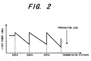
Fig. 2 is a graph showing a level-diagram used for explaining the
operation of the optical transmission system and the method for supervising
the same, according to the first preferred embodiment.
Fig. 3 is a table used for explaining the simulating operation of the
optical transmission system and the method for supervising the same,
according to the first preferred embodiment.
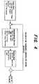
Fig. 4 is a block diagram showing a simulating calculation flow
used for explaining the simulating operation of the optical transmission
system and the method for supervising the same, according to the first
preferred embodiment.
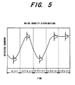
Fig. 5 is a graph showing a received current waveform used for
explaining the simulating operation of the optical transmission system and
the method for supervising the same, according to the first preferred
embodiment.
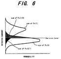
Fig. 6 is a graph showing a noise density distribution of a received
electric signal used for explaining the simulating operation of the optical
transmission system and the method for supervising the same, according to
the first preferred embodiment.
Fig. 7 is a graph showing the relation between a received light
power and a bit-error rate, used for explaining the simulating operation of
the optical transmission system and the method for supervising the same,
according to the first preferred embodiment.
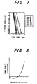
Fig. 8 is a graph showing the relation between a transmission
distance and a power penalty, used for explaining the simulating operation of
the optical transmission system and the method for supervising the same,
according to the first preferred embodiment.
Fig. 9 is a table used for explaining the simulating operation of the
optical transmission system and the method for supervising the same,
according to the first preferred embodiment.
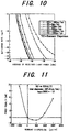
Fig. 10 is a graph showing the variation of simulated bit-error rate,
used for explaining the simulating operation of the optical transmission
system and the method for supervising the same, according to the first
preferred embodiment.
Fig. 11 is a graph showing the variation of simulated power penalty,
used for explaining the simulating operation of the optical transmission
system and the method for supervising the same, according to the first
preferred embodiment.
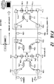
Fig. 12 is a block diagram showing the structure of an optical
transmission system and a method for supervising the same, according to a
second preferred embodiment of the invention.
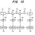
Fig. 13 is a block diagram showing the structure of an optical
transmission system and a method for supervising the same, according to a
third preferred embodiment of the invention.
Fig. 14 is a block diagram showing the structure of an optical
transmission system and a method for supervising the same, according to a
fourth preferred embodiment of the invention.
Fig. 15 is a block diagram showing the structure of an optical
transmission system and a method for supervising the same, according to a
fifth preferred embodiment of the invention.
Fig. 16 is a block diagram showing the structure of an optical
transmission system and a method for supervising the same, according to a
sixth preferred embodiment of the invention.
Fig. 17 is a block diagram showing the structure of an optical
transmission system and a method for supervising the same, according to a
seventh preferred embodiment of the invention.
Fig. 18 is a block diagram showing the structure of an optical
transmission system and a method for supervising the same, according to an
eighth preferred embodiment of the invention.
Fig. 19 is a block diagram showing the structure of an optical
transmission system and a method for supervising the same, according to an
eleventh preferred embodiment of the invention.
Fig. 20 is a block diagram showing the structure of an optical
transmission system and a method for supervising the same, according to a
twelfth preferred embodiment of the invention.
Fig. 21 is a block diagram showing the structure of an optical
transmission system and a method for supervising the same, according to a
thirteenth preferred embodiment of the invention.
Fig. 22 is a block diagram showing the structure of a dispersion
compensator (DC) used in the optical transmission system and the method
for supervising the same, according to the thirteenth preferred embodiment.
Fig. 23 is a block diagram showing the structure of an optical
transmission system and a method for supervising the same, according to a
fourteenth preferred embodiment of the invention.
Fig. 24 is a graph showing the dependency of the power penalty on
the dispersion degree D using a chirp coefficient α as a parameter, in the
optical transmission system and the method for supervising the same,
according to the fourteenth preferred embodiment.
Fig. 25 is a block diagram showing the structure of an optical
transmission system and a method for supervising the same, according to a
fifteenth preferred embodiment of the invention.
Fig. 26 is a block diagram showing the structure of an optical
transmission system and a method for supervising the same, according to a
sixteenth preferred embodiment of the invention.
Fig. 27 is a graph showing the discrimination characteristic of a
frequency discriminator in the optical transmission system and the method
for supervising the same, according to the sixteenth preferred embodiment.
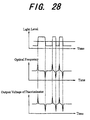
Fig. 28 is a waveform diagram used for explaining the operation of
the optical transmission system and the method for supervising the same,
according to the sixteenth preferred embodiment.
Fig. 29 is a block diagram showing the structure of an optical
transmission system and a method for supervising the same, according to a
seventeenth preferred embodiment of the invention.
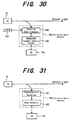
Fig. 30 is a block diagram showing the detailed structure of an
extinction ratio detector in the optical transmission system and the method
for supervising the same, according to the seventeenth preferred
embodiment.
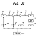
Fig. 31 is a block diagram showing the detailed structure of another
extinction ratio detector in the optical transmission system and the method
for supervising the same, according to the seventeenth preferred
embodiment.
Fig. 32 is a block diagram showing the structure of an optical
transmission system and a method for supervising the same, according to an
eighteenth preferred embodiment of the invention.
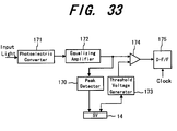
Fig. 33 is a block diagram showing the detailed structure of an
optical receiving device, including a received waveform peak detector, in the
optical transmission system and the method for supervising the same,
according to the seventeenth preferred embodiment.
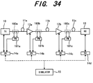
Fig. 34 is a block diagram showing the structure of an optical
transmission system and a method for supervising the same, according to a
nineteenth preferred embodiment of the invention.
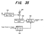
Fig. 35 is a block diagram showing the detailed structure of an SBS
monitor for a transmission line fiber and an optical transmitter controlling
the SBS in the optical transmission system and the method for supervising
the same, according to the nineteenth preferred embodiment.
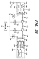
Fig. 36 is a block diagram showing the structure of an optical
transmission system and a method for supervising the same, according to a
twentieth preferred embodiment of the invention.
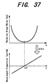
Fig. 37 is a graph used for explaining the measurement theory of
wavelength dispersion in an optical fiber, in the optical transmission system
and the method for supervising the same, according to the twentieth
preferred embodiment.
DETAILED DISCLOSURE OF THE INVENTION
The invention is applicable to an optical communication system,
such as a basic trunk transmission system, a subscriber network system, etc.
First Preferred Embodiment
Fig. 1 shows the outline of an optical transmission system using an
optical transmission simulator, according to a first preferred embodiment of
the invention. In this system, a plurality of EDFAs (Erbium-Doped Fiber
Amplifier) are employed as optical amplifiers.
In Fig. 1, the optical transmission system includes an optical
transmitter (TX) 10, optical fibers 11a, 11b and 11c, repeaters 12a and 12b,
an optical receiver (RX) 13, interface units 14a, 14b, 14c and 14d and an
optical simulator 15. Each repeater is equipped with an optical amplifier,
which amplifies a light signal. The optical fiber 11a connects the optical
transmitter 10 and the repeater 12a. The optical fiber 11b connects
repeaters 12a and 12b. The optical fiber 11c connects the repeater and the
optical receiver 13. The interface units 14a, 14b, 14c and 14d are connected
to the optical transmitter 10, the repeater 12a, the repeater 12b and the
optical receiver 13, respectively. Each of the interface units (SV) 14a, 14b,
14c and 14d monitors and controls each device connected thereto. The
simulator 15 is connected to the interface units 14a, 14b, 14c and 14d with a
communication line, such as a telephone line, a supervisory network, etc.
The simulator 15 simulates the operation of the system based on information
from the interface units (SV) 14a, 14b, 14c and 14d.
The optical transmitter (TX) 10 converts an electric signal into a
light signal having a specific wavelength, and transmits it to the repeater
12a via the optical fiber 11a. For improving transmission reliability, the
system may have two alternative system lines of "0 system" and "1 system"
including. The main system line is usually used, and the other system line
is used when a problem happens on the main system line.
As mentioned above, each of the repeaters 12a and 12b is provided
with an amplifier, which amplifies a received light signal in analog fashion,
and transmits the amplified signal to the following device.
The interface units 14a, 14b, 14c and 14d are supervisory units,
each of which detects estimation parameters from the connected device, and
controls the device.
The simulator 15 is composed of a workstation, application
software for simulation, and the like to estimate an error-bit rate or a Q-factor
of the system based on the current operating condition of each device.
The current operating condition is obtained from the estimation parameters.
In Fig. 1, the communication line shown by a broken line can be
any kind of communication way, besides a telephone line and a supervisory
network.
Now, the operation of the above-described optical transmission
system and a method for supervising the system is described.
Deterioration of an SN (Signal to Noise) ratio and waveform of a
light signal, transmitted through the optical fibers 11a, 11b and 11c mainly
influence transmission quality of the optical transmission system. In more
detail, the transmission quality may be influenced by an extinction ratio of
the optical transmitter 10, an NF noise Figure) of the optical repeaters 12a
and 12b, a Q-factor of the optical receiver 13, a propagation loss of the
transmission line 11a, 11b and 11c, a dispersion coefficient and power
variation (level-diagram) in the transmission line 11a, 11b and 11c.
The SN ratio is deteriorated when a low level light signal is
received by the repeaters 12a and 12b and the optical receiver 13. On the
other hand, a waveform of the light signal is deteriorated due to non-linear
effect in the transmission lines 11a, 11b and 11c when a power of an input
light is too high. The level-diagram represents the variation of power levels
of the light signal, transmitted through the optical fibers 11a, 11b and 11c
and the optical repeaters 12a and 12b, relative to positions on the
transmission line, as shown in Fig. 2.
In this invention, the above described estimation parameters,
which are the factors deteriorating the transmission quality, are monitored
and controlled to obtain the maximum system margin. The system margin
can be maximized based on the Q-factor of the optical receiver 13.
In the first preferred embodiment, the estimation parameters are
actually measured (detected), and the measured values are supplied through
the interface units 14a, 14b, 14c and 14d to the simulator 15. The simulator
15 estimates the bit-error rate or the Q-factor, in accordance with which the
level-diagram of each device and a level discrimination point of the optical
receiver 13 are controlled so that the system margin would be the maximum.
The simulator 15 needs the following parameters to estimate the
bit-error rate or the Q-factor:
• OpticalTransmitter
The estimation parameters about the optical transmitter 10
include a false random signal number (bit number), a transmission speed, a
wavelength of a signal light, an α parameter and an extinction ratio of an
optical modulator, and an SN ratio.
• Optical Fibers (Transmission Lines)
The estimation parameters about the optical fibers 11a, 11b and
11c include first-order dispersion and second-order dispersion for each
wavelength, a non-linear constant, a fiber length, a propagation loss and an
input light power.
• Optical amplifiers ( Repeaters 12a and 12b)
The estimation parameters about the optical amplifiers in the
repeaters 12a and 12b include a signal gain, an NF (Noise Figure) and an
input/output light power.
• Optical Filter
The estimation parameters about an optical filter include a
transmission bandwidth and an insert loss. The optical filter is arranged at
an upward side of the optical receiver 13 for removing ASE (Amplified
Spontaneous Emission) noise.
• Optical Receiver
The estimation parameters about the optical receiver 13 include an
O/E conversion factor, a receiving bandwidth (electric) and a Q-factor.
Next, the sequence for maximize the system margin is described.
For maximizing the system margin, the Q-factor of the received
signal at the optical receiver 13 is controlled to be the maximum or the bit-error
rate is controlled to be the minimum.
(1) Collection of Estimation Parameters
Each device monitors its own estimation parameters except for the
parameters that are known when the system is installed. Those
parameters are supplied through the connected interface unit to the
simulator 15. The simulator 15 may includes a workstation (WS) connected
through a supervisory network for example, using a 10BASE-T.
(2) Calculating Control Factors
An output power of each optical amplifier can be controlled even
after the network is established (installed). The Q-factor of an electric
signal, which is to be discriminated by the optical receiver 13, is defined
based on a noise generated in the optical amplifier and waveform
deterioration caused by a non-linear effect in the optical fibers. The level
discrimination point in the optical receiver 13 is optimized when the system
is installed.
When the input power of an optical amplifier is high (that is, the
output power of the previous optical amplifier is high), an S/N ratio of the
amplifier becomes high. On the other hand, however, waveform
deterioration of the signal becomes remarkable. The output power of each
optical amplifier is calculated so that the Q-factor becomes the maximum.
(3) Control of Devices
In the reverse way of the Collection of Parameters (1), the
simulator 15 controls each optical amplifier contained in a device to have the
optimum output power.
Next, the operation of the simulator 15 is described in conjunction
with Figs. 3 through 11.
Fig. 3 shows the outline of the operation of the simulator 15. In
Fig. 3, the upper column shows the configuration of the system (system
setup), the middle column shows calculating operation (calculation) and the
lower column shows input/output data for each device.
It is assumed that "n" number of wavelengths, λ 1 to λ n, are
multiplexed in the optical fiber 11a passing through an optical amplifier (LA).
In the first preferred embodiment, the number "n" is one (n=1).
When a light signal is transmitted to the optical receiver 13, the
light signal is converted into an electric signal by an O/E converter circuit in
the optical receiver 13. The optical receiver 13 amplifies the electric signal
for discrimination and reproduction. The estimation parameters such as an
O/E conversion efficiency are converted into digital signals by an A/D
converter circuit. The digital signals are supplied to a CPU, and to the
simulator 15 through the interface unit 14d.
In more detail, the optical transmitter 10 supplies the estimation
parameters of a light wavelength, a signal input power, an optical signal
pattern and a chirp level to the simulator 15. The simulator 15 performs
calculation in accordance with an optical signal sequence, shown in Fig. 4,
using the ON/OFF pattern (optical signal pattern) and the chirp level. The
calculation sequence will be described later.
The optical fibers 11a, 11b and 11c supply estimation parameters
of a GVD (Group Velocity Delay), an SPM (Self Phase Modulation), an XPM
(Xross Phase Modulation) and an FWM (Four Wave Mixing). Each optical
amplifier supplies estimation parameters of a gain tilt and a distortion,
caused by an ASE (Amplified Spontaneous Emission) integration.
Based on the data (estimation parameters) from the optical
transmission line, the simulator 15 analyzes a signal waveform in the optical
transmission line in accordance with the Split-Step-Fourier scheme. For
the optical fiber amplifiers, using an EDFA (Erbium-Doped Fiber Amplifier),
a signal quality is estimated based on its gain and ASE noise. For the
simulating calculation of the optical transmission line, data of the fiber
length, propagation loss, dispersion (first-order and second-order) and non-linear
constant (n2) are collected from the optical fibers 11a, 11b and 11c.
The data (estimation parameters) of the gain and NF (Noise Figure) are
collected from the EDFAs.
Fig. 4 shows the flow of the simulating calculation in the simulator
15. In Fig. 4, input data (estimation parameters) including the average
signal power, optical signal pattern and chirp level are supplied to the
simulator 15. In the optical transmission system, the following devices are
further connected an optical fiber, such as an SMF (Single Mode Fiber); a
DSF (Dispersion Shift Fiber); a DCF (Dipersion Compensation Fiber); an
EDFA; an optical filter and other devices.
Based on the propagation loss of the optical fibers 11a, 11b and 11c,
the gain of the optical amplifier (LA) of the EDFA, the gain-tilt and the ASE
integration, the simulator 15 performs a predetermined calculation. The
source data (estimation parameters) and the calculation results are stored in
a data file so that the calculation sequence is controlled based on the data file.
The simulation provides output data of an optical spectrum, a received
waveform (eye-pattern) and a BER (bit-Error Fate).
Figs. 5 to 8 show variation of the bit-error rate and power penalty.
Fig. 5 shows a waveform of the detected current signal, Fig. 6 shows noise
density distribution of the detected current signal, Fig. 7 shows the relation
between detected light power and the bit-error rate, and Fig. 8 shows
variation of power penalty relative to transmission distances. The above-described
simulating calculation is started with Fig. 5 to Fig. 8 so as to obtain
the data shown in Fig. 8. The power penalty represents the variation of the
detected light power relative to transmission distances, using the reference
level of the light power with a distance of zero.
Figs. 9 to 11 show the contents of real calculation, carried out by
the simulator 15. Fig. 9 shows specification of the simulating calculation
both in the cases of a single channel mode (single wavelength) and a WDM
mode. Figs. 10 and 11 show characteristics of the bit-error rate and the
power penalty, calculated from the simulation under the condition shown in
Fig. 9. In the first preferred embodiment, the simulation is carried out for a
single channel transmission.
Referring again to Fig. 1, in the first preferred embodiment, each of
the optical transmitter (TX) 10, the optical transmission line 11, the
repeaters 12a and 12b and the optical receiver (RX) 13 supplies the
estimation parameters (source data) through the interface units (SV) 14 to
the simulator 15. The simulator 15 estimates the BER (Bit-Error Rate) or a
Q-factor, in accordance with the above-described simulating operation, and
controls the level-diagram of each device and the level discrimination point of
the optical receiver 13 so that the optical transmission system has the
maximum margin (system margin) as a whole.
When the optical transmission system is installed, the simulator 15
performs the above-described calculation based on inspected data of each
device, so that the future system margin can be estimated. In addition, the
simulator 15 can calculate the optimum condition for each device, and control
each device based thereon to obtain the maximum system margin at the
beginning.
As described before, the optical transmission system and the
method for supervising the same, according to the first preferred
embodiment, estimation parameters that deteriorate transmission quality
are detected from each device. And, the simulator 15 simulates a bit-error
ratio or a Q-factor, and controls each device so as to minimize the bit-error
ratio or to maximize the Q-factor. Therefore, the optical transmission
system can have the optimum system margin even when the system has
been installed and in operation
Second Preferred Embodiment
Fig. 12 shows an optical transmission system, which performs
automatic detection/control using a supervisory network. The system is
provided with optical fiber amplifiers of EDFA (Erbium-Doped Fiber
Amplifier).
The optical transmission system includes a transmitter/ receiver
110, a repeater 120, a workstation (WS) 130, which automatically collects
estimation parameters (source data) from each device to control the devices
using the supervisory network.
The transmitter/receiver 110 and the repeater 120 are connected
with transmission lines 100a and 100b of optical fibers, which transmits both
of two main signal lights and a supervisory light. The main signal lights are
wavelength-multiplexed to be transmitted in the both directions in the
optical fibers 100a and 100b.
The transmitter/receiver 110 includes optical amplifiers 111a and
111b; optical couplers 112a and 112b, which divides a light by wavelengths
and directions; an E/O converter 113; an O/E converter 114, interface units
(SV) 115a and 115b and a controller 116.
The optical amplifier 111a is connected to an input terminal of the
optical coupler 112a and the interface unit 115a. The optical coupler 112a is
connected at the other input terminal to the E/O converter 113. The
controller 116 is connected to the interface unit 115a, the E/O converter 113,
the O/E converter 114 and to the interface unit 115b. The O/E converter
114 is connected to an output terminal of the optical coupler 112b. The
optical amplifier 111b is connected to the interface unit 115b and to the other
output terminal of the optical coupler 112b.
At the transmission side of the transmitter/receiver 110, an electric
signal is converted into a light signal to have a specific wavelength. The
light signal is supplied to the optical amplifier 111a. At the receiver side,
the light signal with the specific wavelength is received, and is converted into
an electric signal. The electric signal is divided and supplied to subscribers
(not shown), or the like.
The repeater 120 includes optical amplifiers 121a and 121b; optical
couplers 122a, 122b, 122c and 122d, each of which divides a light signal for
each wavelength/direction; E/ O converters 123a and 123b; O/ E converters
124a and 124b; interface units (SV) 125a and 125b and a controller 126.
The repeater 120 amplifies the received light signal in analog fashion, and
also receives/supplies the supervisory signal between the adjacent two
transmitter/receivers 110.
The optical coupler 122a is connected at an input terminal to the
optical coupler 112a in the transmitter/receiver 110 though the optical fiber
100a. The optical coupler 122a is also connected at output terminals to the
optical amplifier 121a and to the O/E converter 124a. The optical amplifier
121 is connected to the interface unit 125a and to an output terminal of the
optical coupler 122b. The optical coupler 122b is connected at the other
input terminal to the E/O converter 123b. The controller 126 is connected to
the O/ E converters 124a and 124b, the E/ O converters 123a and 123b and to
the interface units 125a and 125b. The optical coupler 122d is connected at
output terminals to the O/E converter 124b and the optical amplifier 121b.
The optical coupler 122c is connected at input terminals to the E/O converter
123a and the optical amplifier 121b, and at the output terminal to the optical
coupler 112b in the transmitter/receiver 110 via the optical fiber 100b.
The workstation (WS) 130 includes a simulator and monitor/control
software, and is provided with a common data file for the estimation
parameters, described in the first preferred embodiment. The workstation
(WS) 130 is connected to the transmitter/receiver 110 and the repeater 120 to
supervise the transmission line and each device and to collect the parameters
from each device for automatic control of each device via the supervisory
network.
Next, the operation of the above-described optical transmission
system, using the supervisory network, will be described. The transmitter/receiver
110 converts an electric signal into a light signal to have a specific
wavelength and transmits the light signal to the repeater 120 via the optical
fiber 100a. The transmitter/receiver 110 also receives a light signal, and
converts the light signal into an electric signal to be supplied to subscriber
lines.
The repeater 120 amplifies the received light signal in analog
fashion, and also receives/supplies the supervisory signal between the
adjacent two transmitter/receivers 110. The main signal lights are
wavelength-multiplexed to be transmitted in two ways on the optical fibers
100a and 100b.
The supervisory light, transmitted between the transmitter/receiver
110 and the repeater 120, is designed to have a different wavelength
from the main signal light, but the same in the whole system. In
accordance with the current conditions of the transmission line, transmitter/receiver
110 and the repeater 120, the supervisory light is wavelength-multiplexed
in the optical fibers 100a and 100b. As the supervisory light
has the single wavelength in the whole system, the supervisory light is
transmitted in a single way. In other words, two supervisory lights having
the opposite directions never been multiplexed in the same optical fiber.
The workstation (WS) 130 performs monitor/control operation to
each estimation parameter in the upward and downward lines 100a and
100b on a constant cycle. The simulator in the workstation (WS) 130
collects the estimation parameters via the common data file to calculate the
optimum parameters (control factors).
As described above, according to the second preferred embodiment,
each device is arranged in the supervisory network, and the estimation
parameters are detected from each device using the supervisory network to
control each device automatically. Therefore, the optical transmission
system always operates under the optimum condition.
Third Preferred Embodiment
Fig. 13 shows the outline of an optical transmission system using
an optical transmission simulator, according to a third preferred
embodiment of the invention. In this preferred embodiment, the same or
corresponding components to the first preferred embodiment are indicated
by the same symbols.
In Fig. 13, the optical communication system includes an optical
transmitter (TX) 10; an optical transmission line, including optical fibers 11a,
11b and 11c; repeaters 12a and 12b; an optical receiver (RX) 13, which
receives the light signal; interface units (SV) 14a, 14b, 14c and 14d; and
simulators 15a, 15b, 15c and 15d.
The optical fiber 11a connects the optical transmitter 10 and the
repeater 12a. The optical fiber 11b connects the repeaters 12a and 12b.
The optical fiber 11b connects the repeater 12b and the optical receiver 13.
The interface unit 14a is connected between the optical transmitter 10 and
the simulator 15a. The interface unit 14b is connected between the
repeater 12a and the simulator 15b. The interface unit 14c is connected
between the repeater 12b and the simulator 15c. The interface unit 14c is
connected between the optical receiver 13 and the simulator 15d
Each of the repeaters 12a and 12b is equipped with an optical
amplifier. Each of the interface units 14a, 14b, 14c and 14d monitors and
controls the connected device. Each of the simulators 15a, 15b, 15c and 15d
performs simulating operation based on estimation parameters of each
device detected by the interface unit (SV). The simulators 15a, 15b, 15c and
15d are connected to each other by a communication line, shown by broken
lines, such as a telephone line, a supervisory network, etc.
For instance, a workstation (WS) is arranged at a location where
the optical transmitter (TX) 10 or one of repeaters 12a and 12b is placed.
Each of the simulators 15a, 15b, 15c and 15d may be established by
installing application software, performing the above-mentioned simulation,
in the workstation.
According to the embodiment, a simulator is supplied to each
device, therefore, each simulator (workstation) can simulate the operation of
the corresponding area in parallel. As a result, so that a process time for
simulation and control becomes shorter as compared to the system using a
single simulator for all the devices.
In the third preferred embodiment, shown in Fig. 13, when the
communication line shown by the broken line is removed or ignored and each
simulator monitors and controls the corresponding device independently, the
processing speed can be more improved.
Fourth Preferred Embodiment
Fig. 14 shows the outline of an optical transmission system using
an optical transmission simulator, according to a fourth preferred
embodiment of the invention. In this preferred embodiment, the same or
corresponding components to the preferred embodiment, shown in Fig. 1, are
indicated by the same reference numerals and symbols.
In Fig. 14, the optical transmission system includes optical
transmitters (TX) 20a and 20b; optical transmission lines including optical
fibers 21a, 21b, 21c, 21d, 21e and 21f; repeaters 22a, 22b, 22c and 22d; optical
receivers 23a and 23b; interface units (SV) 14a, 14b, 14c and 14d; and a
simulator 15. In the optical transmission system, an upward circuit is
formed by the optical transmitter 20a, the repeaters 22a and 22b, the optical
fibers 21a, 21b and 21c and the optical receiver 23a. On the other hand, a
downward circuit is formed by the optical transmitter 20b, the repeaters 22c
and 22d, the optical fibers 21d, 21e and 21f and the optical receiver 23b.
The optical transmitter 20a and the optical receiver 23b are
connected to the interface unit 14a. The repeaters 22a and 22c are
connected to the interface unit 14b The repeaters 22b and 22d are
connected to the interface unit 14c. The optical transmitter 20b and the
optical receiver 23a are connected to the interface unit 14d.
In the upward circuit, the optical fiber 21a connects the optical
transmitter 20a and the repeater 22a. The optical fiber 21b connects the
repeaters 22a and 22b. The optical fiber 21c connects the repeater 22b and
the optical receiver 23a. In the downward circuit, the optical fiber 21d
connects the optical receiver 23b and the repeater 22c. The optical fiber 21e
connects the repeaters 22c and 22d. The optical fiber 21f connects the
repeater 22d and the optical transmitter 20b.
The optical transmitters 20a and 20b are designed to transmit
wavelength-multiplexed light signals Each of the repeaters 22a, 22b, 22c
and 22d is equipped with an optical amplifier, which amplifies the light
signal. The optical receivers 23a and 23b are designed to receive the
multiplexed light signals. Each of the interface units 14a, 14b, 14c and 14d
monitors and controls the device that is connected thereto with a
communication line, such as a telephone line, a supervisory network, etc.
The simulator 15 performs simulating operation based on estimation
parameters of each device detected by the interface units 14a, 14b, 14c and
14d.
Each of the optical transmitters 20a and 20b, the repeaters 22a,
22b, 22c and 22d and the optical receivers 23a and 23b is designed to
transmit a wavelength-multiplexed light signal. In the optical fibers 21a,
21b, 21c, 21d, 21e and 21f supervisory signals, which is illustrated by broken
lines, are wavelength-multiplexed to the main light signal.
In this embodiment, the supervisory signals have a wavelength
that is different from the main signal light. The supervisory signals have
the same wavelength in the whole system, and are multiplexed to one fiber
selected from "m" fibers, based on the operating conditions of the optical
fibers 21a, 21b, 21c, 21d, 21e and 21f, multiplexers and the repeaters 22a,
22b, 22c and 22d. As the supervisory lights have the common wavelength
in the whole system, the supervisory lights travel in one way. In other
words, two supervisory lights traveling in the opposite directions are never
multiplexed in the same optical fiber.
According to the above described optical transmission system, the
supervisory lights are wavelength-multiplexed to the main signal light in the
optical fibers 21a, 21b, 21c, 21d, 21e and 21f, so that an additional monitor
network is not required for monitoring and controlling each device.
Fifth Preferred Embodiment
Fig. 15 shows the outline of an optical transmission system using
an optical transmission simulator, according to a fifth preferred embodiment
of the invention. In this preferred embodiment, the same or corresponding
components to the fourth preferred embodiment, shown in Fig. 14, are
indicated by the same reference numerals and symbols.
In Fig. 15, the optical transmission system includes an optical
transmitter 20, an optical transmission line including optical fibers 21a, 21b
and 21c, repeaters 22a and 22b, an optical receiver 23, interface units (SV)
14a, 14b, 14c and 14d and a simulator 15. The interface units 14a, 14b, 14c
and 14d are connected to the optical transmitter 20, the repeater 22a, the
repeater 22b and the optical receiver 23, respectively. The interface units
14a, 14b, 14c and 14d are connected to each other by a communication line,
such as a telephone line, a supervisory network etc. The interface unit 14a
is connected to the simulator 15. The optical fiber 21a connects the optical
transmitter 20 to the repeater 22a. The optical fiber 21b connects the
repeater 22a to the repeater 22b. The optical fiber 21c connects the repeater
to the optical receiver 23.
The optical transmitter 20 transmits wavelength-multiplexed light
signals. Each of the repeaters 22a and 22b is equipped with an optical
amplifier, which amplifies the light signals. The optical receiver 23
receives the multiplexed light signals. Each of the interface units 14a, 14b,
14c and 14d monitors and controls the device connected thereto. The
simulator 15 performs simulating operation based on estimation parameters
of each device detected by the interface units 14a, 14b, 14c and 14d.
In Fig. 15, an upward way and a downward way are formed by the
single transmission line, so that supervisory signals having the different
wavelengths are multiplexed in the transmission line (21a, 21b and 21c) to
perform a two-way transmission. In the figure, broken lines show the
supervisory lights.
In this embodiment, the supervisory signals have the different
wavelengths λ 1 and λ 2 between the upward and downward ways, so that
each device can be monitored and controlled using the single transmission
line.
Sixth Preferred Embodiment
Fig. 16 shows the outline of an optical transmission system using
an optical transmission simulator, according to a sixth preferred
embodiment of the invention. In this preferred embodiment, the same or
corresponding components to the first preferred embodiment, shown in Fig. 1,
are indicated by the same reference numerals and symbols.
In Fig. 16, the optical transmission system includes optical
transmitters 30 and 31, a WDM (Wavelength Division Multiplexer) 32 at a
transmitter side; an optical transmission line including optical fibers 11a,
11b and 11c, repeaters 12a and 12b, a WDM 33 at a receiver side, optical
receivers 34 and 35, interface units (SV) 14a, 14b, 14c and 14d, and a
simulator 15. The interface unit 14a is connected to the optical transmitters
30 and 31 and the WDM 32. The interface units 14b and 14c are connected
to the repeaters 12a and 12b, respectively. The interface unit 14d is
connected to the optical receivers 34 and 35 and the WDM 33. Each of the
interface units 14a, 14b, 14c and 14d is connected to the simulator 15 by a
communication line, such as a telephone line, a supervisory network, etc.
The optical transmitters 30 and 31 transmit different wavelengths
of light signals. Each of the repeaters 12a and 12b is equipped with an
optical amplifier, which amplifies the light signals. The optical receivers 34
and 35 receive the light signals having the different wavelengths. Each of
the interface units 14a, 14b, 14c and 14d monitors and controls the device
that is connected thereto. The simulator 15 performs simulating operation
based on estimation parameters of each device detected by the interface
units 14a, 14b, 14c and 14d.
The WDM 32 at the transmitter side is designed to multiplex light
signals supplied from the transmitters 30 and 31 and transmit the
multiplexed light signal to the optical fiber 11a. On the other hand, the
WDM 33 at the receiver side is designed to divide the multiplexed light
signal supplied from the optical fiber 11c and supply the divided light signals
to the optical receivers 34 and 35.
Generally, in a wavelength-multiplex transmission using an optical
amplifier, levels of an output signal of the amplifier is varied from
wavelength to wavelength. As mentioned in the description of the first
preferred embodiment, the variation of the light level changes non-linear
effect and SN ratio in the optical fiber, therefore, the light level has to be
controlled to have the optimum level for each wavelength. In other words,
it is required that the margin defined by the non-linear effect and SN ratio,
is controlled to have the maximum value.
Accordingly, in this embodiment, the optical transmitters 30 and
31 and the optical receivers 34 and 35, between which different wavelengths
of light signals are transmitted, are connected through the interface units
(SV) 14a, 14b, 14c and 14d to the simulator 15. The characteristics of each
device are detected and transmitted via the interface units (SV) 14a, 14b, 14c
and 14d to the simulator 15. The simulator 15 estimates (calculates) the
bit-error rate or Q-factor, and controls the level-diagram of each wavelength
and the level discrimination point of the optical receivers 34 and 35 so as to
obtain the maximum system margin.
This preferred embodiment can be used when another wavelength
channel is added to the optical transmission system of the first preferred
embodiment. As each device is supervised for each wavelength, the system
can be controlled to operate under the optimum condition automatically.
Seventh Preferred Embodiment
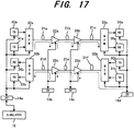
Fig. 17 shows an optical transmission system using an optical
transmission simulator, according to a seventh preferred embodiment of the
invention. The same or corresponding components to shown in Figs. 14 and
16 are indicated by the same reference numerals and symbols.
The seventh preferred embodiment is designed by applying the
optical transmission simulator of the sixth preferred embodiment to the
wavelength-multiplex system, transmitting light signals having the different
wavelengths.
In Fig. 17, the optical transmission system includes an upward
transmission circuit, a downward transmission circuit, interface units 14a,
14b, 14c and 14d and a simulator 15. The upward transmission circuit
includes optical transmitters 30a and 31a, a WDM (Wavelength Division
Multiplexer) 32a; an optical transmission line including optical fibers 21a,
21b and 21c, repeaters 22a and 22b, a WDM 33a at a receiver side and
optical receivers 34a and 35a. The downward transmission circuit includes
optical transmitters 30b and 31b, a WDM (Wavelength Division Multiplexer)
33b; an optical transmission line including optical fibers 21d, 21e and 21f,
repeaters 22c and 22d, a WDM 32b at a receiver side and optical receivers
34b and 35b.
The interface unit 14a is connected to the optical transmitters 30a
and 31a, WDMs 32a and 32b and the optical receivers 34b and 35b. The
interface unit 14b is connected to the repeaters 22a and 22c. The interface
unit 14c is connected to the repeaters 22b and 22d. The interface unit 14d is
connected to the optical transmitters 30b and 31b, WDMs 33a and 33b and
the optical receivers 34a and 35a. The interface unit 14a is connected to the
simulator 15.
The optical transmitters 30a, 31a, 30b and 31b transmit different
wavelengths of light signals. Each of the repeaters 22a, 22b, 22c and 22d is
equipped with an optical amplifier, which amplifies the light signals. The
optical receivers 34a, 35a, 34b and 35b receive the light signals having the
different wavelengths. Each of the interface units 14a, 14b, 14c and 14d
monitors and controls the device that is connected thereto. The simulator
15 performs simulating operation based on estimation parameters of each
device detected by the interface units 14a, 14b, 14c and 14d.
The WDMs 32a and 33b at the transmitter side are designed to
multiplex light signals supplied from the transmitters 30a and 31a, and 30b
and 31b, respectively. On the other hand, the WDMs 33a and 32b at the
receiver side are designed to divide the multiplexed light signal supplied
from the optical fiber 21c and 21d, respectively. A supervisory signal,
shown by a broken line, is wavelength-multiplexed in the optical fibers 21a,
21b, 21c, 21d, 21e and 21f.
As described above, in the wavelength-multiplex transmission
system, the supervisory signal is transmitted using wavelength-multiplexing
technique, so that each device can be monitored and controlled without a
supervisory network.
Eighth Preferred Embodiment
Fig. 18 shows an optical transmission system using an optical
transmission simulator, according to an eighth preferred embodiment of the
invention. The same or corresponding components to the sixth and seventh
preferred embodiments shown in Figs. 16 and 17 are indicated by the same
reference numerals and symbols.
In Fig. 18, the optical transmission system includes optical
transmitters 30 and 31, a WDM (Wavelength Division Multiplexer) 32 at a
transmitter side; an optical transmission line including optical fibers 21a,
21b and 21c, repeaters 12a and 12b, a WDM 33 at a receiver side, optical
receivers 34 and 35, interface units (SV) 14a, 14b, 14c and 14d, and a
simulator 15. The interface unit 14a is connected to the optical transmitters
30 and 31, and to the simulator 15. The interface units 14b and 14c are
connected to the repeaters 12a and 12b, respectively. The interface unit 14d
is connected to the optical receivers 34 and 35. The interface units 14a, 14b,
14c and 14d are connected to each other by a communication line, such as a
telephone line, a supervisory network, etc.
The optical transmitters 30 and 31 transmit different wavelengths
of light signals. Each of the repeaters 12a and 12b is equipped with an
optical amplifier, which amplifies the light signals. The optical receivers 34
and 35 receive the light signals having the different wavelengths. Each of
the interface units 14a, 14b, 14c and 14d monitors and controls the device
that is connected thereto. The simulator 15 performs simulating operation
based on estimation parameters of each device detected by the interface
units 14a, 14b, 14c and 14d.
The WDM 32 at the transmitter side is designed to multiplex light
signals supplied from the transmitters 30 and 31 and transmit the
multiplexed light signal to the optical fiber 21a. On the other hand, the
WDM 33 at the receiver side is designed to divide the multiplexed light
signal supplied from the optical fiber 21c and to supply the divided light
signals to the optical receivers 34 and 35.
In this embodiment, supervisory signal lights, having the different
wavelengths λ 1 and λ 2 in upward and downward directions, are
transmitted over the common transmission line by two-way transmission
using the wavelength multiplexing technique. Therefore, each device can
be monitored and controlled using the single transmission line.
Ninth Preferred Embodiment
In the system using wavelength multiplexing technique, such as
shown in Fig. 18, when the number of wavelength channels are increased,
for example, another optical transmitter (TX) for a different wavelength is
added to the system, output levels of the other wavelength channels may be
changed and a reciprocal action (four-wave-mixing, cross-talk or the like)
may occur.
Accordingly, in the ninth preferred embodiment, when the number
of wavelength channels is increased, a level of a signal on each wavelength
and the distance between every two wavelengths are monitored The
simulator 15 estimates a bit-error rate or a Q-factor, and controls an output
level of each device and a discrimination point of the optical receiver so that
the system has the maximum margin.
According to the embodiment, even if the number of wavelength
channels is increased after the system has been installed and been in
operation, each device can be automatically controlled so that the system
operates under the optimum condition.
Tenth Preferred Embodiment
In the system using wavelength multiplexing, such as shown in Fig.
18, when one wavelength channel becomes out of order in the opposite case
of the ninth preferred embodiment, output levels of the other wavelength
channels may be changed and a reciprocal action (four-wave-mixing, cross-talk
or the like) may occur.
Accordingly, in this embodiment, when a system of a wavelength
channel becomes out of order, a level of a signal on each wavelength and the
distance between every two wavelengths are monitored. The simulator 15
estimates a bit-error rate or a Q-factor, and controls an output level of each
device and a discrimination point of the optical receiver so that the system
has the maximum margin.
According to the preferred embodiment, even if a system of a
wavelength channel becomes out of order during the system is in operation,
each device can be automatically controlled so that the system operates
under the optimum condition.
Eleventh Preferred Embodiment
Fig. 19 shows the outline of an optical transmission system using
an optical transmission simulator, according to an eleventh preferred
embodiment of the invention. In this preferred embodiment, the same or
corresponding components to the first preferred embodiment, shown in Fig. 1,
are indicated by the same reference numerals and symbols.
In Fig. 19, the optical transmission system includes optical
transmitters 40 and 41, a first optical transmission line including optical
fibers 42a, 42b and 42c, a second optical transmission line including optical
fibers 43a, 43b and 43c, repeaters 44a, 44b, 45a and 45b, optical receivers 46
and 47, interface units (SV) 14a, 14b, 14c and 14d, and a simulator 15.
The interface unit 14a is connected to the optical transmitters 30
and 31. The interface unit 14b is connected to the repeaters 44a and 45a.
The interface unit 14c is connected to the repeaters 44b and 45b. The
interface unit 14d is connected to the optical receivers 46 and 47. The
simulator 15 and the interface units 14a, 14b, 14c and 14d are connected to
each other by a communication line, such as a telephone line, a supervisory
network, etc.
The optical transmitters 40 and 41 transmit different wavelengths
of light signals. Each of the repeaters 44a, 44b, 45a and 45b is equipped
with an optical amplifier, which amplifies the light signals. The optical
receivers 46 and 47 receive the light signals having the different wavelengths.
Each of the interface units 14a, 14b, 14c and 14d monitors and controls the
devices that are connected thereto. The simulator 15 performs simulating
operation based on estimation parameters of each device detected by the
interface units 14a, 14b, 14c and 14d.
As shown in Fig. 19, the system of this embodiment includes a pair
of optical transmitters (40 and 41), a pair of optical repeaters (44a-44b and
45a-45b) and a pair of optical receivers (46 and 47). A first transmission
circuit may be formed by the optical transmitter (TX1) 40, the optical fibers
42a and 42b, the repeaters 44a and 44b, and the optical receiver (RX1) 46.
A second transmission circuit may be formed by the optical transmitter
(TX1) 40, the optical fibers 42a and 42b, the repeaters 44a and 44b, and the
optical receiver (RX1) 46. The devices (40-47) can be selected to form a
suitable combination of transmission circuit.
As mentioned in the description of the first preferred embodiment,
the system margin generally depends on an extinction ratio of the optical
transmitter, an NF (Noise Figure) of the optical repeater, a Q-factor of the
optical receiver, and so on. As the devices (40-47) can be selected to form a
suitable combination of transmission circuit in this embodiment, the system
margin can be optimized easily even if some devices do not work well.
For example, even if the optical receiver has an undesirable Q-factor,
the transmission system can be controlled to have an allowable
system margin by selecting an optical transmitter having a preferable
extinction ratio. In contrast, if both the optical transmitter and the optical
receiver have undesirable characteristics, each device can not have an
enough margin, although the system margin may be in the allowable range.
Consequently, to obtain a preferable system margin totally, the average of
the margin for the devices should be constant.
Accordingly, in this embodiment, the simulator 15 selects the
combination of devices, forming the transmission system, so as to obtain the
maximum system margin in total. As a result, it is possible to secure a
large range of system margin in total.
Twelfth Preferred Embodiment
Fig. 20 shows the outline of an optical transmission system using
an optical transmission simulator, according to a twelfth preferred
embodiment of the invention. In this preferred embodiment, the same or
corresponding components to the eleventh preferred embodiment, shown in
Fig. 19, are indicated by the same reference numerals and symbols.
In Fig. 20, the optical transmission system includes optical
transmitters 40 and 41, a WDM (Wavelength Division Multiplexer) 50 at a
transmitter side; an optical transmission line including optical fibers 42a,
42b and 42c, repeaters 44a and 44b, optical switches or optical tunable filters
51 and 52; optical receivers 46 and 47, interface units (SV) 14a, 14b, 14c and
14d, and a simulator 15.
The interface unit 14a is connected to the optical transmitters 40
and 41, and to the simulator 15. The interface units 14b and 14c are
connected to the repeaters 44a and 44b, respectively. The interface unit 14d
is connected to the optical switches (optical tunable filters) 51 and 52 and to
the optical receivers 46 and 47. The interface units 14a, 14b, 14c and 14d
are connected to each other by a communication line, such as a telephone
line, a supervisory network, etc.
The optical transmitters 40 and 41 transmit different wavelengths
of light signals. Each of the repeaters 44a and 44b is equipped with an
optical amplifier, which amplifies the light signals. The optical receivers 46
and 47 receive the light signals having the different wavelengths. Each of
the interface units 14a, 14b, 14c and 14d monitors and controls the device(s)
that is (are) connected thereto. The simulator 15 performs simulating
operation based on estimation parameters of each device detected by the
interface units 14a, 14b, 14c and 14d.
The WDM 50 is designed to multiplex light signals supplied from
the transmitters 40 and 41 and transmit the multiplexed light signal to the
optical fiber 42a. Each of the optical switches (or optical tunable filters) 51
and 52 is designed to switch a light signal supplied from the optical fiber 42c.
The interface unit 14d controls the optical switches (or optical tunable filters)
51 and 52 and the optical receivers (RX1 and RX2) 46 and 47 to switch them
selectively.
The light signal supplied from the optical transmitters (TX1 and
TX2)40 and 41 are multiplexed by the WDM 50, then transmitted via the
optical fiber 42a and the repeaters 44a and 44b to the optical switches (or
optical tunable filters) 51 and 52. At the optical switches (or optical tunable
filters) 51 and 52, the transmitted light signal is selectively supplied to one of
the optical receivers (RX1 and RX2) 46 and 47.
In the above-described transmission system, each device is selected
and controlled by using the optical switches (or optical tunable filters) 51 and
52, so that necessary components (devices) can be automatically selected and
combined to establish the suitable network that provides the maximum
system margin in total.
Thirteenth Preferred Embodiment
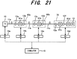
Fig. 21 shows the outline of an optical transmission system using
an optical transmission simulator, according to a thirteenth preferred
embodiment of the invention. In this preferred embodiment, the same or
corresponding components to the first preferred embodiment, shown in Fig. 1,
are indicated by the same reference numerals and symbols.
In Fig. 21, the optical communication system includes an
optical transmitter (TX) 10; an optical transmission line, including optical
fibers 11a, 11b and 11c; repeater units 60a and 60b; an optical receiver unit
70; interface units (SV) 14a, 14b, 14c and 14d; and a simulator. Each device
is supervised via the simulators (SV) 14a, 14b, 14c and 14d based on the
calculation of the simulator 15.
The optical fiber 11a connects the optical transmitter 10 to the
repeater unit 60a. The optical fiber 11b connects the repeater units 60a and
60b to each other. The optical fiber 11b connects the repeater unit 60b to
the optical receiver unit 70. The interface units 14a, 14b, 14c and 14d are
respectively connected to the optical transmitter 10, the repeater unit 60a,
the repeater unit 60b and the optical receiver unit 70.
The repeater unit 60a includes optical amplifiers 12a and 12b, and
a DC (Dispersion Compensator) 61a, connected between the optical
amplifiers 12a and 12b. The repeater unit 60b includes optical amplifiers
12c and 12d, and a DC (Dispersion Compensator) 61b, connected between
the optical amplifiers 12c and 12d. The optical receiver unit 70 includes
optical amplifiers 12e and 12f, an optical receiver (RX) 13 and dispersion
compensators 61c and 61d. The dispersion compensator 61c is connected
between the optical amplifiers 12e and 12f, and the dispersion compensator
61d is connected between the optical amplifiers 12f and the optical receiver
13.
Each of the interface units 14a, 14b, 14c and 14d monitors and
controls the device connected thereto. The simulator 15 performs
simulating operation based on estimation parameters of each device detected
by the interface units (SV) 14a, 14b, 14c and 14d. The interface units 14a,
14b, 14c and 14d and the simulator 15 are connected to each other by a
communication line, shown by broken lines, such as a telephone line, a
supervisory network etc.
The optical transmitter 10 transmits a wavelength-multiplexed
light signal. Each of the dispersion compensators 61a, 61b, 61c and 61d is
designed to compensate wavelength distribution of the optical fibers. The
simulator 15 controls each compensator via the interface unit.
In the optical receiver unit 70, the optical amplifiers 12e and 12f
amplify the light signal supplied from the optical transmitter 10. Each of
the dispersion compensators (DC) 61c and 61d compensates transmission
loss in the optical fibers 11a, 11b and 11c and in the dispersion compensators
61a and 61b.
The optical transmission system of this embodiment is established
by adding the dispersion compensators (DC) 61a, 61b, 61c and 61d, which
compensate wavelength dispersion in the optical fibers 11a, 11b and 11c, to
the optical repeater and optical receiver (RX) 13 of the first preferred
embodiment, shown in Fig. 1. In this embodiment, shown in Fig. 21, each of
the dispersion compensators (DC) 61a, 61b, 61c and 61d is built-in each
optical amplifier of the optical repeaters 60a and 60b, and the optical receiver
unit (RX) 70.
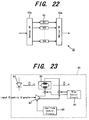
Fig. 22 shows the structure of the dispersion compensator (DC) 61a.
The other DCs 61b, 61c and 61d have the same structure as the DC 61a. In
Fig. 22, the dispersion compensator (DC) 61a is composed of a plurality of
dispersion compensator elements 62 (DC1, DC2, ..., DCN) and optical
switches 63a and 63b, which selects one of the dispersion compensator
elements 62 (DC1, DC2, ..., DCN).
In general, as a transmission line fiber, two kinds of fibers are used.
One of them is a DSF (Dispersion Shift Fiber) having a wavelength
dispersion of around zero (±3.5ps/nm/km) at a wavelength of 1.55 µm, and
the other one is an SMF (Single Mode Fiber) having a larger wavelength
dispersion (16 to 20ps/nm/km) at a wavelength of 1.55 µm. In this
embodiment, the SMFs are employed. In the case where the SMFs are
used, a dispersion compensator is usually used for compensating wavelength
dispersion of the fiber.
In practice, as a wavelength dispersion varies fiber to fiber, the
dispersion compensator connected thereto is not always best for the
transmission fiber. The dispersion compensators (DC) 61a, 61b, 61c and
61d, shown in Fig. 21, can be controlled via the interface units (SV) 14a, 14b,
14c and 14d, so that the dispersion of each optical fiber can always be
compensated under the optimum condition. For controlling the
compensation rate, for example, as shown in Fig. 22, the optical switches 63a
and 63b select one of the dispersion compensator elements 62 (DC1, DC2, ...,
DCN).
As another way for controlling the compensation rate, for example,
a PLC (Planar Lightwave Circuit) can be used, which is described in
"Dispersion Compensation Test using PLC type of Light Compensation
Equator," C-337, 1994 Electro-Communication Society Spring Conference.
As described above, in the optical transmission system, according to
the thirteenth preferred embodiment, the compensation rate of each
dispersion compensator (DC) is controlled via the interface units (SV) 14a,
14b, 14c and 14d based on the calculation result of the simulator 15. As a
result, it is possible to maximize the bit-error rate or minimize Q-factor so as
to obtain the maximum system margin.
This embodiment is also useful for an optical transmission system
using DSF type of optical fibers, because the DSF has variation of
wavelength dispersion around zero level. In other words, it is possible to
obtain the maximum system margin when the compensation rates of the
dispersion compensators are controlled properly.
Fourteenth Preferred Embodiment
Fig. 23 shows the structure of an optical transmitter 80 in an
optical transmission system using an optical transmission simulator,
according to a fourteenth preferred embodiment of the invention. This
embodiment is established by adding a function for controlling a chirp
parameter (showing variation of wavelength of a light source) to the optical
transmission system according to the first preferred embodiment shown in
Fig. 1, or the eighth preferred embodiment shown in Fig. 18. The detail of
the controlling operation has been described, for instance, in the report of
"High-speed, low power optical modulator with adjustable chirp parameter,"
by S. K Korotky et al, Integrated Photonics Research 1991, TuG2, pp.53-54.
The fourteenth embodiment will be described in accordance with this
publication.
In Fig. 23, the optical transmitter includes a semiconductor laser
81 as a light source, an optical modulator 82, an optical modulator driving
circuit 83, a bias control circuit 84 and an output amplitude control circuit 85.
The semiconductor laser 81, such as a DFB laser (Distributed Feedback
Laser), supplies a light signal having a specific wavelength. The optical
modulator 82 is of a Mach-Zehnder type, which amplitude-modulates a light
supplied from the semiconductor laser 81.
The optical modulator driving circuit 83 drives the optical
modulator 82. The optical modulator driving circuit 83 is supplied with an
input electric signal to generate output signals having the opposite logical
levels to be supplied to electrodes of the optical modulator 82. The bias
control circuit 84 controls a bias voltage to be applied to each electrode of the
optical modulator 82. The output amplitude control circuit 85
independently controls the amplitudes of modulating waves to be supplied to
the electrodes of the optical modulator 82.
As described above, according to the optical transmitter 80 of this
embodiment, a wavelength chirp level can be controlled by an outside circuit.
In general, when a dispersion rate D (ps/nm) of an optical fiber is
positive, the waveform of the transmitted light becomes broader. In the
opposite case, the waveform of the transmitted light becomes newer.
Such phenomenon occurs in the case where the chirp parameter α of the
light source is positive (0< α). On the other hand, when the chirp
parameter α is negative (α<0), the dispersion D of the optical fiber has the
opposite characteristics.
Fig. 24 shows the variation of power penalty relative to the
variation of dispersion "D" for each condition of chirp parameter α. For
example, when the chirp parameter α is zero, the dispersion D is increased
due to a widened waveform and the power penalty is increased as well in
general. However, if the chirp parameter α is controlled to meet the
condition of α <0, the waveform is narrowed to make the power penalty
lower. On the other hand, if the dispersion D becomes D<0, the waveform is
narrowed by influences both of the dispersion of the transmission line and
the chirp parameter, so that the power penalty is increased rapidly.
Accordingly, the optical transmission system of this embodiment,
the chirp parameter α of the optical transmitter 80 is controlled by the
outside circuit so as to optimize the waveform of the received signal.
Referring again to Fig. 23, an output light of the semiconductor
laser 81 is supplied to the optical modulator 82 and is modulated in
amplitude. The optical modulator 82 of Mach-Zehnder type controls the
phases of the divided two light signals with a voltage to change degree of
interference so that the amplitude modulation is performed. The optical
modulator 82 is supplied at the electrodes with the output signals of the
optical modulator driving circuit 83, which has the opposite logical
characteristics, so that the amplitude of each signal is controlled by the
output amplitude control circuit 85. Further, the bias control circuit 84
controls a bias voltage applied to each electrode of the optical modulator 82.
Thus, the chirp parameter α is well controlled.
According to the fourteenth preferred embodiment, the chirp
parameter of the semiconductor laser 81 is controlled to optimize the
waveform of the received signal, and therefore, the maximum system margin
is obtained.
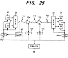
Fifteeenth Preferred Embodiment
Fig. 25 shows the outline of an optical transmission system using
an optical transmission simulator, according to a fifteenth preferred
embodiment of the invention. In this preferred embodiment, the same or
corresponding components to the sixth preferred embodiment, shown in Fig.
16, are indicated by the same reference numerals and symbols.
In Fig. 25, the optical transmission system includes optical
transmitters 30 and 31, a WDM (Wavelength Division Multiplexer) 32 at a
transmitter side; an optical transmission line, including optical fibers 11a,
11b and 11c, repeaters 12a and 12b, a WDM 33 at a receiver side, optical
receivers 34 and 35, interface units (SV) 14a, 14b, 14c and 14d; a simulator
15; and a wavelength detector 90.
The interface unit 14a is connected to the optical transmitters 30
and 31, the WDM 32 and the wavelength detector 90. The interface units
14b and 14c are connected to the repeaters 12a and 12b, respectively. The
interface unit 14d is connected to the optical receivers 34 and 35 and the
WDM 33. Each of the interface units 14a, 14b, 14c and 14d is connected to
the simulator 15 by a communication line, such as a telephone line, a
supervisory network, etc.
The optical transmitters 30 and 31 transmit different wavelengths
of light signals. Each of the repeaters 12a and 12b is equipped with an
optical amplifier, which amplifies the light signals. The optical receivers 34
and 35 receive the light signals having the different wavelengths. Each of
the interface units 14a, 14b, 14c and 14d monitors and controls the device
that is connected thereto. The simulator 15 performs simulating operation
based on estimation parameters of each device detected by the interface
units 14a, 14b, 14c and 14d. The wavelength detector 90 detects and
collects the wavelength of each signal transmitted through the optical fiber
11a.
The WDM 32 at the transmitter side is designed to multiplex light
signals supplied from the transmitters 30 and 31 and to transmit the
multiplexed light signal to the optical fiber 11a. On the other hand, the
WDM 33 at the receiver side is designed to divide the multiplexed light
signal supplied from the optical fiber 11c and supply the divided light signals
to the optical receivers 34 and 35.
The optical transmission system of this embodiment is formed by
adding the wavelength detector 90, which measures the light spectrum of a
transmitted light and detects its wavelength, to the above mentioned optical
transmission system, shown in Fig. 16. Output data of the wavelength
detector 90 are collected by the simulator 15 via the interface unit (SV) 14a.
The transmission side WDM 32 is designed to control the wavelengths of
signals supplied from the transmitters (TX) 30 and 31.
In general, when a plurality of signals having different
wavelengths are transmitted over a single transmission line, a so-called four-wave-mixing
of a non-linear phenomenon is generated in the transmission
line. This phenomenon is remarkable when a DSF (Dispersion Shift Fiber),
having a wavelength dispersion around zero, is employed as the
transmission line. As a result, a light having an undesirable wavelength
enters into the main signal, and therefore, the transmission characteristics of
the system are remarkably deteriorated (Reference: Communication System
Study Group of Communication Society CS96-43).
Accordingly, it is required to control the wavelengths of signals to
be transmitted through the same optical fiber so that an undesirable
wavelength of signal does not enter into the wavelength of the main signal.
However, even if the wavelength are adjusted when the system is installed,
the four-wave-mixing phenomenon may occurs, because the wavelengths of
the transmission signals are later changed to ensure a high system margin
and/or the wavelengths may be changed with time after the installation of
the system.
In this embodiment, the wavelength detector 90 detects the
wavelengths of the transmission lights, and the detected data are supplied to
the simulator 15 via the interface unit 14a. The simulator 15 calculates
condition of the wavelengths of the signal lights so as not to generate the
four-wave-mixing. In response to the calculation result, the simulator 15
controls wavelengths of lights traveling through the optical fibers 11a, 11b
and 11c.
As described above, according to the fifteenth preferred
embodiment, the wavelength detector 90 detects and collects the wavelength
of each signal. The detected data are supplied to the simulator 15 via the
interface unit 14a. The simulator 15 calculates a wavelength that does not
generate the four-wave-mixing, and controls the wavelength of each
transmission signal to approximate to the calculated optimum wavelength.
Therefore, even if the wavelengths of the signal lights are changed after the
installation of the system, the maximum system margin can be obtained.
Sixteenth Preferred Embodiment
Fig. 26 shows the structure of an optical transmission system using
an optical transmission simulator, according to a sixteenth preferred
embodiment of the invention. In this preferred embodiment, the same or
corresponding components to the first preferred embodiment, shown in Fig. 1,
are indicated by the same reference numerals and symbols.
Modifying the above mentioned optical transmission system of the
first preferred embodiment, forms this preferred embodiment, in which a
wavelength chirp level of an optical transmitter is monitored. As the
wavelength chirp level corresponds to variation of the light frequency,
hereinafter, the chirp level is referred to as the light frequency variation for
easier understanding.
In Fig. 26, a reference numeral 140 indicates an optical coupler,
which divides an output signal of an optical transmitter 10; a reference
numeral 141 indicates an optical frequency discriminator; and a reference
numeral 142 indicates a peak detector, the output of which is supplied to an
interface unit SV (not shown).
The optical coupler 140 divides the output light of the optical
transmitter 10 based on its wavelength and direction, and supplies the
divided signal to an optical fiber and to the optical frequency discriminator
141.
The optical frequency discriminator 141 may be formed by a Mach-Zehnder
interferometer, which has the discrimination characteristic, shown
in Fig. 27. As shown in Fig. 27, the output power varies in response to the
optical frequency of a signal light, so that the frequency of the light can be
discriminated from the peak voltage.
The peak detector 142 detects the peak of the output signal of the
optical frequency discriminator 141 and supplies the detected value to the
interface unit (SV) as the peak value of the frequency variation.
Next, the operation of the above constructed optical transmission
system and of a method for supervising the same will be described. The
output light from the optical transmitter 10 is divided by the optical coupler
140 into two lights, one of which is supplied to the optical fiber 11 and the
other one is supplied to the optical frequency discriminator 141. The optical
frequency discriminator 141 performs frequency discrimination to the input
light in accordance with the discrimination characteristic, shown in Fig. 27.
The output voltage of the optical frequency discriminator 141 is supplied via
the peak detector 142 to the interface unit (SV).
Fig. 28 shows waveform diagrams, used for describing the
operation of this embodiment. The graph shows an optical frequency of the
input signal and the output voltage of the optical frequency discriminator
relative to a pulse waveform of the input signal.
In general, a variation Δf of the optical frequency is calculated
from the following equation (1) based on an optical pulse waveform S(t), its
differentiated value and above-mentioned chirp parameter α:
Δf=(α/4π) × (1/S(t)) × (dS(t)/dt)
According to the equation (1), when the chirp parameter α is
greater than zero (α >0), the optical frequency changes in the opposite
polarities (codes) as diIferentiated pulses at points where the level of the
pulse waveform starts rising up and falling down, as shown in Fig. 28. The
frequency discriminator 141 supplies an output signal having a pulse
waveform that is almost proportional to the variation of the optical frequency.
The peak detector 142 detects the peak point of the output waveform of the
frequency discriminator 141, so that the peak value of the frequency
variation of the transmitted light signal.
In the simulator, an optical pulse waveform is formed in response
to the variation of the optical frequency as a phase variation. As understood
from the equation (1), actually detecting the frequency variation is equivalent
to calculating the frequency variation from the chirp parameter α and the
optical pulse waveform. The frequency variation, however, can be
monitored more precisely by the actual detection. In this preferred
embodiment, the chirp parameter can be monitored.
As explained above, according to the sixteenth preferred
embodiment, The chirp quantity, which correlates to the frequency variation,
is monitored via the interface unit (SV) 14. In other words, the chirp
parameter is monitored by monitoring the frequency variation based on the
waveform of the output light supplied from the optical transmitter 10.
Therefore, the simulator 15 can calculate (estimate) an error rate and a bit-error
rate of the optical receiver in accordance with the chirp parameter.
Seventeenth Preferred Embodiment
Fig. 29 is a diagram showing the structure of an optical
transmission system using an optical transmission simulator, according to a
seventeenth preferred embodiment of the invention. In this preferred
embodiment, the same or corresponding components to the first preferred
embodiment, shown in Fig. 1, are indicated by the same reference numerals
and symbols.
Modifying the above mentioned optical transmission system of the
first preferred embodiment, shown in Fig. 1, forms this preferred
embodiment, in which an extinction ratio of an optical transmitter is detected
and monitored The extinction ratio represents a ratio between light levels
in non-emission condition and an emission condition.
In Fig. 29, the optical transmission system includes an optical
transmitter (TX) 10, optical fibers 11a, 11b and 11c, repeaters 12a and 12b,
an optical receiver (RX) 13, interface units 14a, 14b, 14c and 14d, an optical
simulator 15 and an extinction ratio detector 150. Each of the repeaters 12a
and 12b is equipped with an optical amplifier, which amplifies a light signal.
The optical fiber 11a connects the optical transmitter 10 and the repeater
12a. The optical fiber 11b connects repeaters 12a and 12b. The optical
fiber 11c connects the repeater and the optical receiver 13.
The interface units 14a, 14b, 14c and 14d are connected to the
extinction ratio detector 150, the repeater 12a, the repeater 12b and the
optical receiver 13, respectively. Each of the interface units (SV) 14a, 14b,
14c and 14d monitors and controls each device connected thereto. The
simulator 15 is connected to the interface units 14a, 14b, 14c and 14d with a
communication line, such as a telephone line, a supervisory network, etc.
The simulator 15 simulates the operation of the system based on information
from the interface units (SV) 14a, 14b, 14c and 14d.
The optical transmitter (TX) 10 converts an electric signal into a
light signal having a specific wavelength, and transmits it to the repeater
12a via the optical fiber 11a.
Fig. 30 is a block diagram illustrating the detailed structure of the
above-mentioned extinction ratio detector 150. In Fig. 30, the extinction
ratio detector 150 includes a sampling oscilloscope, provided with an O/E
converter; and a processor 153, which detects an extinction ratio using
automatic detecting program. The sampling oscilloscope 152 is supplied
with a divided dock signal (f0/N), generated in the optical transmitter 10, as
a trigger in order to receive a part of the output light supplied from the
optical transmitter 10. The processor 153 is connected to the interface unit
14a.
The sampling oscilloscope 152 and the processor 153 form the
extinction ratio detector 150 as a whole to supply the detected extinction
ratio to the interface unit (SV) 14a.
In the optical transmission system, each device is supervised via
the interface unit (SV) 14a (14b, 14c and 14d) in accordance with the
calculation result of the simulator 15. In the optical transmitter 10, the
extinction ratio detector 150 detects and monitors the extinction ratio of the
waveform of the output signal light supplied from the optical transmitter 10.
In the sampling oscilloscope 152, the O/E converter converts the
received light signal into a corresponding electric signal to be supplied to the
automatic detecting program processor 153. The automatic detecting
program processor 153 detects an extinction ratio of the output light signal at
regular intervals in accordance with the automatic detecting program, and
supplies the extinction ratio to the interface unit (SV) 14.
In more detail, the extinction ratio detector 150 measures the
average (A) of light levels in an emission mode and the average (B) of light
levels in a non-mission mode. The extinction ratio is calculated by the
following equation (2):
Extinction Ratio [dB] =10 log (A/B)
The detecting operation of the sampling oscilloscope 152 is carried
out in accordance with the automatic detecting program, which is easily
formed from conventional application software.
In stead of the extinction ratio detector 150, another type of
extinction ratio detector 160, shown in Fig. 31, can be used.
Fig. 31 is a block diagram showing the detailed structure of the
extinction ratio detector 160. In Fig. 31, the extinction ratio detector 160
includes a photoelectric (O/E) converter 161 and a peak detector 162, in stead
of the sampling oscilloscope 152 and the processor 153, used in the extinction
ratio detector 150. The peak detector 162 can have the same structure as
the peak detector shown in Fig. 26.
In the extinction ratio detector 160, a high level point (A) and a low
level (B) of an output light signal supplied from the optical transmitter 10 to
detect an extinction ratio thereof. The extinction ratio detector 160 can
detect the extinction ratio easily as compared to the unit 150, shown in Fig.
30.
As described above, in the optical transmission system according to
the seventeenth preferred embodiment, the extinction ratio, which is one
parameter of calculation in the simulator 15, is monitored via the interface
unit (SV) 14a. In accordance with the calculation result of the simulator 15,
other parameters influencing deterioration of the transmission quality can be
controlled to minimize an bit-error rate or to maximize a Q-factor to obtain
the maximum system margin.
Eighteenth Preferred Embodiment
Fig. 32 shows the structure of an optical transmission system using
an optical transmission simulator, according to an eighteenth preferred
embodiment of the invention. In this preferred embodiment, the same or
corresponding components to the first preferred embodiment, shown in Fig. 1,
are indicated by the same reference numerals and symbols.
This preferred embodiment is formed by modifying the above
mentioned optical transmission system of the first preferred embodiment,
shown in Fig. 1. In this preferred embodiment, a peak of a light signal
received by an optical receiver is detected and monitored.
In Fig. 32, the optical transmission system includes an optical
transmitter (TX) 10, optical fibers 11a, 11b and 11c, repeaters 12a and 12b,
an optical receiver (RX) 13, interface units 14a, 14b, 14c and 14d, an optical
simulator 15 and a peak detector 170. Each of the repeaters 12a and 12b is
equipped with an optical amplifier, which amplifies a light signal. The
optical fiber 11a connects the optical transmitter 10 and the repeater 12a.
The optical fiber 11b connects repeaters 12a and 12b. The optical fiber 11c
connects the repeater and the optical receiver 13.
The interface units 14a, 14b, 14c and 14d are connected to the
optical transmitter 10, the repeater 12a, the repeater 12b and the optical
receiver 13, respectively. Each of the interface units (SV) 14a, 14b, 14c and
14d monitors and controls each device connected thereto. The simulator 15
is connected to the interface units 14a, 14b, 14c and 14d with a
communication line, such as a telephone line, a supervisory network etc.
The simulator 15 simulates the operation of the system based on information
from the interface units (SV) 14a, 14b, 14c and 14d.
The optical transmitter (TX) 10 converts an electric signal into a
light signal having a specific wavelength, and transmits it to the repeater
12a via the optical fiber 11a. The peak detector 170 detects a peak of a
signal light received by the optical receiver 13. The peak detector 170
supplies its output signal to the interface unit (SV) 14d.
Fig. 33 is a block diagram illustrating the detailed structure of the
above-mentioned peak detector 170. In Fig. 33, the peak detector 170
includes a photoelectric (O/E) converter 171; an equalizing amplifier 172; a
threshold voltage generator 173; a level discriminator 174; and a D flip-flop
(D-FF). The photoelectric converter 171 is connected to the equalizing
amplifier 172, connected to the peak detector 170. The level discriminator
174 is connected at input terminals to the equalizing amplifier 172 and the
threshold voltage generator 173, and at an output terminal to the D flip-flop
175. The peak detector 170 and the threshold voltage generator 173 are
connected to the interface unit 14d.
The photoelectric (O/E) converter 171 converts an input light signal
into an electric signal. The equalizing amplifier 172 includes an AGC
(Automatic Gain Control), which equally amplifies the electric signal,
supplied from the photoelectric converter 171. The threshold voltage
generator 173 generates a threshold voltage to be supplied to the level
discriminator 174 for level detection The level discriminator 174 compares
the equally amplified signal and the threshold voltage to perform level
discrimination. The D flip-flop (D-FF) 175 timing-discriminates the level-discriminated
data in accordance with a sampling clock.
The equalizing amplifier 172 supplies an output signal to the
interface unit (SV) 14d via the peak detector 170. The threshold voltage
generator 173 supplies a threshold voltage to each of the level discriminator
174 and the interface unit (SV) 14d.
Next, the above-described optical transmission system and a
method for supervising the same will be described. An input light signal
supplied to the optical receiver 13 is converted into an electric signal by the
photoelectric converter 171, and the electric signal is amplified by the
equalizing amplifier 172 to have a predetermined amplitude. The equally
amplified signal is compared to the threshold voltage supplied from the
threshold voltage generator 173, and is discriminated high or low relative to
the threshold voltage. The discriminated signal is reproduced by the D-FF
175 using the sampling clock.
The equally amplified signal is also supplied to the peak detector
170 so that the high level (VH) and low level (VL) of the signal are detected
as its peaks to be supplied to the interface unit (SV) 14d. The threshold
voltage (VTH), which is generated by the threshold voltage generator 173
and supplied to the level discriminator 174, is transferred to the interface
unit (SV) 14d.
For performing the optimum control of the transmission system
using the threshold voltage (VTH), calculated by the simulator 15, it is
required to know a high level (VH) and a low level (VL) of the received signal.
According to this embodiment, the threshold voltage VTH is controlled in
response to variation of the high level (VH) and the low level (VL), so that the
optical transmission system can be controlled precisely.
For instance, in the simulator 15, the threshold voltage VTH0 may
be calculated by performing normalization with the parameters VH, VL,
VTH. The normalizing calculation is carried out in accordance with the
following equation (3):
VTH0= (VL-VTH)/(VH-VL)
As described above, according to the eighteenth preferred
embodiment, the optical receiver 13 is provided with the peak detector 170,
which detects the peak of a received waveform. The peak detector 170
detects a high level (VH) and a low level (VL) of the received signal, and
those levels are monitored together with the threshold voltage VTH0 by the
simulator 15 via the interface unit 14d. As a result, the simulator 15 can
control the threshold voltage VTH to have the optimum value, and therefore,
the transmission system can have the maximum system margin.
Nineteenth Preferred Embodiment
Fig. 34 is a diagram showing the structure of an optical
transmission system using an optical transmission simulator, according to a
nineteenth preferred embodiment of the invention. In this preferred
embodiment, the same or corresponding components to the first preferred
embodiment, shown in Fig. 1, are indicated by the same symbols.
To the first preferred embodiment shown in Fig. 1, this preferred
embodiment is formed by adding a function for detecting and monitoring a
non-linear phenomenon SBS (Stimulated Brillouin Scattering) in a
transmission line.
In Fig. 34, the optical transmission system includes an optical
transmitter (TX) 10, optical fibers 11a, 11b and 11c, repeaters 12a and 12b,
an optical receiver (RX) 13, interface units 14a, 14b, 14c and 14d, an optical
simulator 15, optical couplers 180a, 180b and 180c and optical power
monitors 181a, 181b and 181b.
The optical transmitter (TX) 10 converts an electric signal into a
light signal having a specific wavelength, and transmits it to the repeater
12a via the optical fiber 11a. Each of the repeaters 12a and 12b is equipped
with an optical amplifier, which amplifies a light signal. The optical fiber
11a connects the optical transmitter 10 to the repeater 12a through the
optical coupler 180a. The optical fiber 11b connects repeaters 12a and 12b
through the optical coupler 180b. The optical fiber 11c connects the
repeater 12b to the optical receiver 13 through the optical coupler 180c.
The interface unit 14a is connected to the optical transmitter 10
and the optical power monitor 181a, which is connected to the optical coupler
180a. The interface unit 14b is connected to the repeater 12a and the
optical power monitor 181b, which is connected to the optical coupler 180b.
The interface unit 14c is connected to the repeater 12b and the optical power
monitor 181c, which is connected to the optical coupler 180c. The interface
unit 14d is connected to the optical receiver 13.
Each of the interface units (SV) 14a, 14b, 14c and 14d monitors and
controls each device connected thereto. The simulator 15 is connected to the
interface units 14a, 14b, 14c and 14d with a communication line, such as a
telephone line, a supervisory network, etc. The simulator 15 simulates the
operation of the system based on information from the interface units (SV)
14a, 14b, 14c and 14d.
The optical coupler 180a, which is arranged at the input end of the
optical fiber 11a, divides a light signal transmitted from the optical
transmitter 10. The optical power monitor 181a monitors power of
input/output light traveling through the optical fiber 11a. The optical
coupler 180b, which is arranged at the input end of the optical fiber 11b,
divides a light signal transmitted from the repeater 12a. The optical power
monitor 181b monitors power of input/output light traveling through the
optical fiber 11b. The optical coupler 180c, which is arranged at the input
end of the optical fiber 11c, divides a light signal transmitted from the
repeater 12b. The optical power monitor 181c monitors power of
input/output light traveling through the optical fiber 11c.
Each pair of the optical coupler (180a, 180b and 180c) and the
optical power monitor (181a, 181b and 181c) form a monitor means as a
whole, which monitors an input light power at the input end of the optical
fiber (11a, 11b and 11c) and a light power returned through the optical fiber
(11a, 11b and 11c). Each of the optical power monitors 181a, 181b and 181c
supplies the detected light level to the simulator 15 via the interface unit
(14a, 14b, 14c and 14d).
Fig. 35 is a block diagram showing the detailed structure of the
optical transmitter 10, in which an SBS (Stimulated Brillouin Scattering) in
the transmission line is monitored and controlled. In Fig. 35, the optical
transmitter 10 includes a bias current source 182, a low frequency oscillator
183, a semiconductor laser 184, an optical modulator 186 and an optical
modulator driving circuit 185.
The bias current source 182 supplies bias current to the
semiconductor laser 184. The low frequency oscillator 183 is used for
current modulation. The semiconductor laser 184 outputs a light signal.
The optical modulator driving circuit 185 drives the optical modulator 186 in
response to an input electric signal. The optical modulator 186 modulates
the light signal supplied from the semiconductor laser 184. An output level
of the low frequency oscillator 183 is controlled via the interface unit (SV) 14a
by an output circuit.
In general, as known in the conventional optical transmitter
described in "Study Group of Optical Communication System OCS91-49,
Electric Information Communication Society CS96-43," when the input
power of an optical fiber is increased over a specific level, a backscattering
light is increased in power in response to the non-linear phenomenon (SBS:
Stimulated Brillouin Scattering). When the backscattering light is
increased in the optical fiber, the output light of the optical fiber is saturated.
Accordingly, in this embodiment, the SBS is monitored at the input
end of each optical fiber (11a, 11b and 11c) and a spectrum width of the light
source 184 is increased by current modulation. As a result, the input power
level in which the backscattering light starts increasing, which is a so-called
SBS threshold value, is improved.
In the optical transmitter 10, the output level of the low frequency
oscillator 183 can be controlled by an output circuit. As a degree of the
current modulation is controllable, the spectrum width of the light source
184 is controllable as well. The current modulation can be carried out with
a voltage source, besides the current source.
The output light of the semiconductor laser 184 is supplied to the
optical modulator 186, and is modulated by the optical modulator 186, driven
by the optical modulator driving circuit 185.
The simulator 15 monitors the input light and the backscattering
light of each optical fiber via the interface units 14a, 14b, 14c and 14d, using
the optical couplers 180a, 180b and 180c, the optical power monitor 181a,
181b and 181c. The simulator 15 controls the light source 184 to have a
spectrum width that does not cause any of the optical fibers 11a, 11b and 11c
to have the SBS.
As described above, the optical transmission system, according to
the nineteenth preferred embodiment, the spectrum width of the light source
184 is controlled by an output circuit. As a result, the spectrum width of the
light source 184 can be controlled while monitoring the SBS at the input end
of each optical fiber (11a, 11b and 11c), and therefore, the transmission
system operates under a stable condition without SBS.
Twentieth Preferred Embodiment
Fig. 36 shows the structure of an optical transmission system using
an optical transmission simulator, according to a twentieth preferred
embodiment of the invention. In this preferred embodiment, the same or
corresponding components to the first preferred embodiment, shown in Fig. 1,
are indicated by the same reference numerals and symbols.
To the first preferred embodiment shown in Fig. 1, this
embodiment is established by adding a function for monitoring wavelength
dispersion of a transmission line.
In Fig. 36, the optical transmission system includes an optical
transmitter unit 190, optical fibers 11a, 11b and 11c, repeaters 12a and 12b,
an optical receiver unit 200, interface units 14a, 14b, 14c and 14d and an
optical simulator 15.
The optical transmitter unit 190 converts an electric signal into a
light signal having a specific wavelength, and transmits it to the repeater
12a via the optical fiber 11a. Each of the repeaters 12a and 12b is equipped
with an optical amplifier, which amplifies a light signal. The optical fiber
11a connects the optical transmitter 190 to the repeater 12a. The optical
fiber 11b connects repeaters 12a and 12b through the optical coupler 180b.
The optical fiber 11c connects the repeater 12b to the optical receiver unit
200 through the optical coupler 180c.
The interface units 14a, 14b, 14c and 14d are connected to the
optical transmitter unit 190, the repeater 12a, the repeater 12b and the
optical receiver unit 200, respectively. Each of the interface units (SV) 14a,
14b, 14c and 14d monitors and controls each device connected thereto. The
simulator 15 is connected to the interface units 14a, 14b, 14c and 14d with a
communication line, such as a telephone line, a supervisory network, etc.
The simulator 15 simulates the operation of the system based on information
from the interface units (SV) 14a, 14b, 14c and 14d.
The optical transmitter unit 190 includes an oscillator 191, a
wavelength variable light source 192 (wavelength λ 1), a reference light
source 193 (wavelength λ 2), an optical transmitter (TX) 194 (wavelength
λ 0) and a transmitter side WDM 195. The oscillator 191 is connected to
the wavelength variable source 192 and the reference light source 193. The
WDM 195 is connected to each of the frequency variable light source 192, the
reference light source 193 and the optical transmitter 194. The WDM 195
wavelength-multiplexes the three light signals, supplied from the devices
192, 193 and 194, having the different wavelengths of λ 0, λ 1 and λ 2 to
generate a single light to be transmitted to the optical fiber 11a.
The optical receiver unit 200 includes a receiver side WDM 201; an
optical receiver 202; a first light receiving element 203; a second light
receiving element 204; and a phase comparator 205. The WDM is
connected to each of the optical receiver 202, the first light-receiving element
203 and the second light-receiving element 204. The first and second light
receiving elements 203 and 204 are connected to the phase comparator 205.
The WDM 201 divides a received signal into three signals having
the wavelengths of λ 0, λ 1 and λ 2. The optical receiver 202 receives the λ 0
component of light. The first light receiving element 203 receives the λ 1
component of light and converts it into an electric signal. The second light
receiving element 204 receives the λ 2 component of light and converts it into
an electric signal. The phase comparator 205 detects the phase difference
between the lights supplied from the first and second light receiving
elements 203 and 204.
In the optical transmitter unit 190, the wavelength variable light
source 192 and the reference light source 193 perform modulating process in
accordance with signals from the oscillator 191. In the optical receiver unit
200, the receiver side WDM 201 divides a received signal into three signals
having the wavelengths of λ 0, λ 1 and λ 2, and supplies the divided λ 0, λ 1
and λ 2 components to the optical receiver 202, the first light receiving
element 203 and the second light receiving element 204, respectively. The
signals received by the first and second light receiving elements 203 and 204
are supplied to the phase comparator 205, which detects the phase difference
between those two signals.
The phase difference between the λ 1 and λ 2 components is
detected in the optical receiver unit 200, while the simulator 15 changes the
output wavelength of the wavelength variable light source 192 in the optical
transmitter unit 190. If a similar transmission line is employed in the
system, the WDMs can be omitted to perform the same operation.
Then, data for wavelength dependency of the phase difference is
transferred via the interface unit (SV) 14d to the simulator 15.
Fig. 37 shows the relation between a relative group delay and a
wavelength dispersion, which is used for explaining the theory for measuring
wavelength dispersion of the optical fibers. In Fig. 37, the phase difference
between the λ 1 component and the λ 2 component corresponds to the
relative group delay of the optical fiber. In general, as the wavelength
dispersion of an optical fiber can be calculated based on the wavelength
differential of the relative group delay, the wavelength dispersion of each
wavelength can be obtained by differentiating the phase difference data with
the wavelength. Such wavelength dispersion data may be easily detected
by a detector, for example "83567A" by HP.
As described above, in the optical transmission system according to
the twentieth preferred embodiment, the simulator 15 calculates the
wavelength dispersion of the transmission line (11a, 11b and 11c) based on
the detected phase difference. The simulator 15 optimizes each parameter
based on the wavelength dispersion, and controls each device via the
interface units (SV) 14a, 14b, 14c and 14d based on the optimized
parameters so that the transmission system has the minimum bit-error rate
or the maximum Q-factor.
In more detail, the dependency of the relative group delay on the
wavelength is actually measured for the reference light source and the
variable wavelength light source, then the simulator 15 calculates the
wavelength dispersion of the transmission line (11a, 11b and 11c) based on
the measured value. In accordance with the wavelength dispersion of the
transmission line, the simulator 15 calculates a bit-error rate and a Q-factor
of the system. In addition, the simulator 15 calculates the optimum value
for each parameter, and then controls each device via the interface unit (SV)
14 so that the bit-error rate has the minimum value or the Q-factor has the
maximum value to obtain the maximum system margin.
The optical transmission system and the method for supervising
the same, having the above-described advantages, may be applied to an
optical subscriber network system to obtain the maximum system margin.
Preferably, the invention is applied to a system that needs additional optical
amplifiers in response to, for instance, a demand for increasing the
transmission capacity.
Each embodiment is applicable to a basic trunk transmission
system, a subscriber network system, etc. However, the invention is, of
course, applicable to any kinds of device equipped with a system for
transmitting a light signal.
It is dear that none of the embodiments limits type, number and
connection way of optical amplifiers, optical couplers, filters, WDMs and each
detector; kind of parameters for each device; and the way of simulation.
According to the invention, predetermined estimation parameters
are monitored from each device to estimate (calculate) a bit-error rate or Q-factor.
Then, the simulator calculates the optimum control values so as to
minimize the bit-error rate or to maximize the Q-factor, and controls each
device in accordance with the optimum control values. As a result, the
optical transmission system has the maximum system margin. Therefore,
even if some devices operate out of their margin, the transmission system
still operates in a range of its system margin as a whole. Consequently, it is
not always required to establish an auxiliary line in addition to the main
transmission line.
It will be understood that the above description of the present
invention is susceptible to various modifications, changes and adaptations,
and the same are intended to be comprehended with the meaning and range
of equivalents of the appended claims.