EP0873035A2 - Réseau local ayant des moyens de conversion - Google Patents
Réseau local ayant des moyens de conversion Download PDFInfo
- Publication number
- EP0873035A2 EP0873035A2 EP98201120A EP98201120A EP0873035A2 EP 0873035 A2 EP0873035 A2 EP 0873035A2 EP 98201120 A EP98201120 A EP 98201120A EP 98201120 A EP98201120 A EP 98201120A EP 0873035 A2 EP0873035 A2 EP 0873035A2
- Authority
- EP
- European Patent Office
- Prior art keywords
- network
- atm
- network interface
- connection
- cell
- Prior art date
- Legal status (The legal status is an assumption and is not a legal conclusion. Google has not performed a legal analysis and makes no representation as to the accuracy of the status listed.)
- Withdrawn
Links
Images
Classifications
-
- H—ELECTRICITY
- H04—ELECTRIC COMMUNICATION TECHNIQUE
- H04Q—SELECTING
- H04Q11/00—Selecting arrangements for multiplex systems
- H04Q11/04—Selecting arrangements for multiplex systems for time-division multiplexing
- H04Q11/0428—Integrated services digital network, i.e. systems for transmission of different types of digitised signals, e.g. speech, data, telecentral, television signals
- H04Q11/0478—Provisions for broadband connections
-
- H—ELECTRICITY
- H04—ELECTRIC COMMUNICATION TECHNIQUE
- H04L—TRANSMISSION OF DIGITAL INFORMATION, e.g. TELEGRAPHIC COMMUNICATION
- H04L12/00—Data switching networks
- H04L12/54—Store-and-forward switching systems
- H04L12/56—Packet switching systems
- H04L12/5601—Transfer mode dependent, e.g. ATM
- H04L2012/5603—Access techniques
- H04L2012/5609—Topology
- H04L2012/5612—Ring
-
- H—ELECTRICITY
- H04—ELECTRIC COMMUNICATION TECHNIQUE
- H04L—TRANSMISSION OF DIGITAL INFORMATION, e.g. TELEGRAPHIC COMMUNICATION
- H04L12/00—Data switching networks
- H04L12/54—Store-and-forward switching systems
- H04L12/56—Packet switching systems
- H04L12/5601—Transfer mode dependent, e.g. ATM
- H04L2012/5614—User Network Interface
-
- H—ELECTRICITY
- H04—ELECTRIC COMMUNICATION TECHNIQUE
- H04L—TRANSMISSION OF DIGITAL INFORMATION, e.g. TELEGRAPHIC COMMUNICATION
- H04L12/00—Data switching networks
- H04L12/54—Store-and-forward switching systems
- H04L12/56—Packet switching systems
- H04L12/5601—Transfer mode dependent, e.g. ATM
- H04L2012/5619—Network Node Interface, e.g. tandem connections, transit switching
- H04L2012/562—Routing
-
- H—ELECTRICITY
- H04—ELECTRIC COMMUNICATION TECHNIQUE
- H04L—TRANSMISSION OF DIGITAL INFORMATION, e.g. TELEGRAPHIC COMMUNICATION
- H04L12/00—Data switching networks
- H04L12/54—Store-and-forward switching systems
- H04L12/56—Packet switching systems
- H04L12/5601—Transfer mode dependent, e.g. ATM
- H04L2012/5638—Services, e.g. multimedia, GOS, QOS
- H04L2012/564—Connection-oriented
- H04L2012/5642—Multicast/broadcast/point-multipoint, e.g. VOD
-
- H—ELECTRICITY
- H04—ELECTRIC COMMUNICATION TECHNIQUE
- H04L—TRANSMISSION OF DIGITAL INFORMATION, e.g. TELEGRAPHIC COMMUNICATION
- H04L12/00—Data switching networks
- H04L12/54—Store-and-forward switching systems
- H04L12/56—Packet switching systems
- H04L12/5601—Transfer mode dependent, e.g. ATM
- H04L2012/5638—Services, e.g. multimedia, GOS, QOS
- H04L2012/5646—Cell characteristics, e.g. loss, delay, jitter, sequence integrity
- H04L2012/5652—Cell construction, e.g. including header, packetisation, depacketisation, assembly, reassembly
Definitions
- the invention relates to a local, after the asynchronous transfer mode (ATM) working network, in particular a unidirectional or bidirectional ring network several stations and these and / or further networks with further stations assigned network interfaces (ATM transceivers), each with a transmission and receive ring connection, the information exchange digital via ATM cells, in their header field address information, in particular bundle identifiers (VPI, virtual path identifier) and connection identifiers (VCI, virtual channel identifier).
- the invention also concerns one for use in such a network suitable ATM cell and a network interface for such a local Network and finally a stackable ATM unit consisting of a variety of network interfaces to set up a switching device (switch).
- ATM asynchronous transfer mode
- An ATM cell is made up of a cell header and one Information field (payload) that contains the information to be transmitted are.
- the ATM technology is used in different transmission services, such as Data transmission services, voice transmission services, video services (e.g. Video conferences, video databases) or when transmitting multimedia information, where voice, data, and video information with each other are combined.
- An ATM network can be both private and public.
- a public ATM network is e.g. the B-ISDN network (broadband integrated service digital network). Private or public ATM networks can due to the given ATM standards are interconnected.
- ATM With ATM, cells are transmitted continuously on each transmission section. If no user information is currently to be sent, specially marked ones are used Empty cells sent. This means that the ATM user cells are separated from one another in time transmitted independently because the time intervals on the line between neighboring Utility cells are usually different. This type of transfer is therefore called asynchronous. With this, ATM provides an asynchronous transmission of fixed length useful cells.
- control cells in their Control information information field, e.g. for the control unit of a network interface, contain.
- a virtual path in turn represents a group of virtual channels.
- VCI virtual channel identifier
- VPI virtual path identifier
- a single connection (unicast connection) between a single user of a first station and a User of a second station.
- the connection When connecting between a first and several other users the connection as a multicast connection. If it is such a multiple connection by any number of other users one speaks of a broadcast connection.
- EP 0 614 296 A2 describes a local ATM network as mentioned above Kind known in which both user cells and control cells as useful cells are processed.
- a station is assigned to each network interface.
- the user cells contain the actual information, e.g. Messages or data from the user of this connection. If a virtual Connection, for example, for the transmission of voice signals (telephone conversation) is used, the information field of the user cell contains voice data.
- a control cell in its information field control information, for example for the internal coordination of the mediation function are needed, especially to establish a connection or after to dismantle the transmission of information.
- connection is established as follows:
- a transmission station wants to connect to at least one Receiving station is first at least one control cell with a query about generated the state of the receiving station.
- the at least one receiving station sends at least one control cell with the information after receiving the query about their condition.
- the sending station forms after receiving the status information at least one control cell to establish a connection if the state of the allows at least one receiving station to connect. Then follows the establishment of a connection and the transmission of information. The dismantling of the Connection takes place in reverse order.
- From US 5 600 795 is an after the asynchronous transfer mode ATM working local network known, in which the connection establishment in similar This is done in that firstly a control arrangement assigned to a transmitting station, a control cell supplied by the transmitting station with a feasible one Request for a single (unicast) or multiple connection (multicast / broadcast) of a user of the transmitting station. Subsequently the control cell is sent out to at least one user Receiving station, the control cell in its information field at least one Information about the user, the address of the sending station and a user-related ID for the reverse connection contains.
- each station assigned control arrangement takes place after receipt of the delivered by the transmitting station Control cell the generation of a control cell to be sent to the transmitting station, who in their information field at least one information about the address of the assigned receiving station and a user-related identifier for the outgoing connection contains.
- each station is its own Network interface assigned.
- the ATM cell consists of a piece of information with a length of 48 Byte and a header of 5 bytes in length.
- the cell head is there structured differently, depending on whether it is an ATM cell that via an interface between a station and the network (UNI, user network interface) or between two different networks (NNI, network network interface) is transmitted.
- the first 4 bits form the cell header the GFC function (generic flow control). This enables overload situations in the network due to exceeding specified bandwidths prevent. This is followed by a bit sequence of 8-bit VPI and 16-bit VCI Definition of the virtual channel or the virtual path.
- the following Information of the header cell relates to the type of cell (PT, payload type), A distinction is made in this prior art between user cells and control cells. More information is given by the cell loss priority (CLP, cell loss priority) and the cell header checksum (HEC, header error control) performed. The latter areas PT, CLP, HEC are for UNI / NNI cells identical. In contrast, the NNI cell differs from the UNI cell in that instead of the GFC area provided for the UNI cell, the area for path identification (VPI) is extended from 8 to 12 bits.
- CLP cell loss priority
- HEC header checksum
- the invention has for its object a network or a network interface of the type mentioned above and one for use in one to develop such a suitable ATM cell network so that the ring-internal communication is simplified without the ring-external specified Standard is violated.
- This task is carried out in a network or a network interface initially mentioned type solved in that the at least one network interface Implementation means are assigned to at least partial and reversible conversion of available data bytes in the header field of the ATM cell in a network-specific identifier.
- an ATM cell for use in a network of the type mentioned Kind of the solution according to the invention takes place in that a port extender forming multiplexer / demultiplexer device is assigned, via which the data transfer to several stations arranged on connection ports.
- the invention is distinguished from the prior art from that by converting the available data bytes within the header bit the ATM cell into the network-specific identifier a much more flexible data transfer can take place within the network.
- the solution according to the invention is based on the approach that standardization according to the UNI / NNI standard must only be maintained where this is due to the environmental conditions is required.
- the prescribed standard does not have to go to the stations be respected. Rather, a system-specific header format can be used here be used. Both of the formats mentioned differ in their meaning the header bit, but not the length of the header.
- the network When entering the According to the invention, the network thus becomes the one corresponding to the UNI / NNI standard Header translated into the network-specific header bit.
- the Cell leaves the network whose header is in the UNI / NNI specific format back transformed. The selection of those used for the ring-specific identifier The header bit can be freely selected.
- header translation table includes such that at least one Part of the header field area not occupied by the standardized VPI & VCI bit sequence is easy to overwrite with the network-specific identifier Customization options.
- the header field translation table is used during the Signaling (call setup) so defined that the VPI & VCI bit sequence is retained for the connection identifier and that, on the other hand, the desired ones network-specific information are taken into account in the identifier.
- a first section of the identifier can preferably be used to distinguish unicast (Single connections), multicast (multiple connections) and broadcast (distribution connections) be used.
- Another, in the following further subsection II mentioned section of the network-specific identifier serves to specify the destination of the ATM cell, i.e. to determine the network interface at which the Target station is connected.
- the network-specific one is in unicast mode Identifier the specification of the network interface at which the desired destination is.
- An assignment table (small broadcast / multicast table), which is called during the signaling phase by the so-called call handler using the for the connection desired stations is defined.
- This assignment table on Station exit is necessary because of that to a certain broadcast / multicast connection belonging cells a global, i.e. essentially identical, Use VPI & VCI pattern.
- the Assignment table (broadcast / multicast table) therefore fits the global VPI & VCI Sample of a connection in the ring network to the participant-specific VPI & VCI Samples according to UNI / NNI standard. This adjustment takes place during the signaling phase.
- the effect of this assignment table is that a deletion notice for the cell is read from this table in the event that it is in the Multicast operation is a cell that is not related to the network interface owned station.
- a special embodiment of the solution according to the invention is that at least one network interface has a multiplexer / demultiplexer, via which at least two stations together on the network interface are connected. Accordingly, each network interface is now appropriate the multiplicity of the multiplexer or demultiplexer several stations assigned, which are operated from the same network interface can.
- the network interface thus has the property of a so-called port Extenders based on a fixed number of connection ports for each station contains. Those arriving from the stations at a comparatively slow speed Cells are multiplexed onto the high speed link transformed to the send ring connections of the network interface. In the opposite direction, those from the network interface arriving cells on the different connection ports for the stations in the Distributed in the sense of demultiplexing.
- This multiplex and demultiplex function of the port extender can be realized without the basic described above
- the structure of the network interface device must be changed. There are only measures to be taken to further expand the network-specific area To store additional information on the basis of which the The fact is taken into account that now not only per network interface one but several stations are connected via the port extender.
- the port extender is particularly advantageous in that the UNI / NNI standard is present at the input or the output of the port extender, i.e. is shifted there at the network interface.
- the network-specific identifier consists of two bit sections x, y, the a bit section x for identification of the respective multiplexer / demultiplexer connected connection ports and the other bit section y to identify the Network interface is used for which the ATM cell is intended.
- the first bit section x added and the second bit section y shortened.
- This is another assignment table from which the call handler receives the information, which connection ports on the respective network interface and in what way are addressed. So if in unicast mode the transmitter is a certain one The receiving station selects the call handler via the assignment known to it given the coding information for the bit section x.
- the data bits are then filled in such a way that in the x-range the information for the respective connection port and in the y-range the identification of those containing this connection port Network interface is stored.
- the solution according to the invention finds a particular use in that that a network interface is set up that a local non-blocking N x N Switching unit forms when the data rate of the connection between port Extender and transceiver is greater than the sum data rate of the individual port extender on. or outputs.
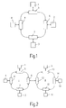
- FIG. 1 in terms of its basic structure from the State of the art known local after the asynchronous transfer mode ATM working network provides four stations 1-4, each via a network interface 5-8 are connected to a ring network.
- the data connection between one of the stations 1-4 to a receiving station within the network takes place in accordance with the ATM transmission method.
- Each network interface points to this 5-8 Send and receive ring connections on, for transmission of cells are provided.
- Each network interface 5-8 has one (not Coupling device shown in more detail, which via buffer memory with the ring connections and the station is coupled and passes on the cell current. Details of the structure of such a network interface are in the prior art Technique of EP 0 614 296 A2 described.
- FIG. 2 shows a local network arrangement which consists of two local ATM networks I, II consists.
- Each of the networks has a number of stations 1, 3, 4 and 9, 10, 11, each with separate network interfaces 5, 7, 8 and 13, 14, 15 with the associated network are connected. Both networks are above one another coupled network interfaces 6 and 12 connected.
- coupled networks can transfer the ATM cells, for example, from a Transmitting station in the area of the network I to a receiving station in the area of Network II take place (or vice versa).
- FIG. 3 shows the basic structure of a further local ATM network.
- the network interface 5 in the Difference to the networks shown in FIGS. 1 and 2 are at a network interface 5 several stations 1a, 1b, 1c connected.
- This is the network interface 5 expanded by a multiplexer or demultiplexer 20, the one Coupling of the ATM cells from the parallel on the network interface 5 adjacent station 1a, 1b, 1c into the ring connections of the network interface 5 enables.
- those from the network at the receiving ring connection Network interface 5 received ATM cells in the demultiplexing function of the Multiplexers / demultiplexers 20 in turn the desired stations 1a, 1b, 1c assigned.
- the network interface 5 with a so-called port Extender equipped, at which according to its port number several stations 1a, 1b, 1c can be connected.
- the port extender for the network interface shown in FIG. 3 5 can also be implemented in the same way for any other of the illustrated Network interfaces.
- the multiplicity of each port extender is also principally not limited.
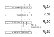
- 4a shows in principle the structure of an ATM cell according to the standard, which consists of there is a total of 53 bytes, with 48 bytes for the transmission of information (payload) and 5 bytes for controlling the transfer in the form of header data are provided. These 5 bytes form the so-called cell header.
- FIG. 4b shows the structure of the cell head provided for in accordance with standardization a cell that is transmitted from a station (user) to the network (network).
- This standard is called UNI (user network interface).
- the following 8 Bits are used to define the virtual path (VPI) while the ones following it following 16 bits for the definition of the virtual channel (VCI) are provided. Additional bits in the header are provided for the identification of the Cell type (PT, payload type), the cell loss priority (CLP, cell loss priority) and the cell header checksum (HEC, header error control).
- PT Cell type
- CLP cell loss priority
- HEC header error control
- Fig. 4c shows the structure of the cell head in the event that the ATM cell via a network network interface (NNI, network network interface) from one local ATM network to another should (see, for example, Fig. 2).
- NNI network network interface
- Fig. 4d the structure of an ATM cell as shown by is now shown in principle the implementation of the UNI / NNI standard into the network-specific standard is obtained. First, it can be assumed that the areas PT, CLP and HEC of the cell head remain unchanged from the standardized format.
- VPI & VCI Within the header area reserved for VPI & VCI, for example 28 bits includes, there is an area of for example 16 bits, because 10 bits for the VPI & VCI information when building 1024 connections are sufficient.
- the remaining bit range is according to UNI / NNI Default set to zero.
- this bit area (cf. FIG. 4d) is now used for the network-specific (internal ring) identifier used, i.e. overwrite the free bits.
- the identifier consists of a first section I (UMB) in which the information is stored, whether it is a unicast, a multicast or a Broadcast connection.
- the other sub-area II (DEST-ID) includes in essentially the address information for the ATM cell. This will be in detail received further below.
- another section III (CP) is for Priority information or reserved for the cell type.
- the first subarea I identifies the network-specific one Header format the property of the cell, whether it's a unicast, Multicast or broadcast connection cell.
- the cell structure used in the further sub-area II is the cell structure used in the further sub-area II as follows:
- the case is considered that it is a Unicast operation and each network interface according to FIGS. 1 and 2 exactly a station is assigned.
- the address is in section II the network interface to which the desired target station is connected (Port ID).
- FIG. 5 b shows the cell structure in area II if, in contrast to FIG. 5a is a multicast or broadcast operation. Then is in Section II the address of the network interface from which the ATM cell is sent (SENDER-ID). This causes the ATM cell to go out from the transmitter station runs through the entire network until it is finally on Sender arrives.
- SENDER-ID the address of the network interface from which the ATM cell is sent
- the structure of the further subarea II is the network-specific one Identifier shown if in the case of unicast operation a network interface 3 is equipped with a port extender. In this case there is one Subdivision is provided in a first bit sequence x and a second bit sequence y.
- the first bit string x stores the identifier for the connection port to which the desired target station is connected.
- the second bit sequence shows y the identifier of the network interface at which the connection port of the Target station is located.
- 5d shows the cell structure in the case of multicast operation for one with one Port Extender equipped network interface according to Fig. 3.
- the in Section II Bit pattern sequence shown takes into account which connection ports within a addressed network interface for the connection are desired, for example here the connection ports 0, 2, 4, 6, while the other connection ports 1, 3, 5, 7 should not participate in the multicast connection.
- the sender ID is used as the destination address of the ATM cell, since all stations connected within the network into the connection are involved.
- the call handler is responsible for defining the assignment table in the network interface known in the signaling phase at which network interface the station with which the connection is to be established.
- the address is thus included in the free bits in section II the network interface to which the station is connected is. If it is a control cell, the target for this control cell is written into the free bit area. It can be for example, a control cell for the CPU in the same network interface act.
- the ATM cell to the ring exit forwarded (in the case of a bidirectional ring network to both outputs). If it is the network interface with the port ID matches, the cell is forwarded to the station exit. There is the Back translation of the header bit into the standardized format, in which the im not used VPI & VCI area existing bits are set to zero.
- a corresponding mode of operation results when the cells are in the opposite direction to run.
- the call handler determines which network interfaces to be transferred, i.e. what stations in the connection are involved. This is taken into account in the assignment table by means of which the standardized UNI / NNI format in the network-specific header bit structure is implemented.
- those with the ring-specific pass through Header format provided ATM cells the ring network and in each network interface the cell is copied and forwarded to the ring exit until the Cell finally got back to the send network interface and deleted there becomes.
- Each network interface checks whether the cell is intended for it. If if this is not the case, the copied cell is deleted. If so, will the copied cell is forwarded to the output of the network interface to the station.
- the call handler first communicated how the assignment of each to the connection ports the port extender connected stations to the respective network interfaces is designed. This is the system-specific structuring, which is communicated to the call handler, for example in the form of a database.
- the call handler determines during the signaling phase that via which network interface the connection to the desired target station must expire.
- sub-area II of the network-specific identifier are therefore not only data bit in area y for the identification of the network interface but data bits are also provided in the area x which contain an identifier which of the connection ports connected to the network interface to the desired one Station heard.
- the cells are transferred as described under 1. Even the reverse transformation the network-specific header format into the standardized Format is again done by resetting the bits in the x or y range to zero.
- the signaling phase again defines which stations are involved in the connection.
- the call handler is now Known to which network interfaces the connection ports for the on the connection belong to participating stations.
- a bit pattern is defined in each network interface, which it is characteristic of which of the connection ports of the port extender ATM cells should receive.
- Each network interface is therefore dependent on the ones to be addressed Connection ports each have different such bit patterns.
- section II of the network-specific identifier is used as the address, as under 2. and 3. described, again the address of the sender specified as port ID.
- the cells are now transferred as follows:
- Each cell is connected from the transmitter connector port to the high speed line leads to the network interface, leads and enters the network from there. If now the cell has entered the next network interface, the depends further processing depends on whether at least one of the connection ports of this network interface is involved in the connection.
- the cell is forwarded to the ring exit and enters the next network interface.
- the processing method described now takes place equally in each of the ATM cell reached network interfaces until the cell returned to the transmit interface arrives and is deleted there.
Applications Claiming Priority (2)
| Application Number | Priority Date | Filing Date | Title |
|---|---|---|---|
| DE19715799 | 1997-04-16 | ||
| DE19715799A DE19715799C2 (de) | 1997-04-16 | 1997-04-16 | Lokales Netzwerk mit Umsetzmitteln |
Publications (2)
| Publication Number | Publication Date |
|---|---|
| EP0873035A2 true EP0873035A2 (fr) | 1998-10-21 |
| EP0873035A3 EP0873035A3 (fr) | 2000-03-22 |
Family
ID=7826635
Family Applications (1)
| Application Number | Title | Priority Date | Filing Date |
|---|---|---|---|
| EP98201120A Withdrawn EP0873035A3 (fr) | 1997-04-16 | 1998-04-08 | Réseau local ayant des moyens de conversion |
Country Status (4)
| Country | Link |
|---|---|
| US (1) | US6529511B1 (fr) |
| EP (1) | EP0873035A3 (fr) |
| JP (1) | JPH10322376A (fr) |
| DE (1) | DE19715799C2 (fr) |
Cited By (4)
| Publication number | Priority date | Publication date | Assignee | Title |
|---|---|---|---|---|
| EP0981230A2 (fr) * | 1998-08-14 | 2000-02-23 | Philips Corporate Intellectual Property GmbH | Commutateur avec transfert complète de l'entête de la cellule |
| EP1047230A2 (fr) * | 1999-04-22 | 2000-10-25 | Telefonica, S.A. | Commutateur a faisceaux pour un réseau a mode de transfert asynchrone |
| US6466577B1 (en) | 1999-04-12 | 2002-10-15 | Alcatel Communications, Inc. | Method and apparatus for point-to-point and point-to-multipoint connections in an ATM network |
| EP1271331A1 (fr) * | 2001-06-28 | 2003-01-02 | Nokia Corporation | Méthode de validation d'une communication entre tâches et système de traitement utilisant une telle méthode |
Families Citing this family (7)
| Publication number | Priority date | Publication date | Assignee | Title |
|---|---|---|---|---|
| US6775282B1 (en) * | 1999-12-27 | 2004-08-10 | Intel Corporation | Bus communication |
| US7353295B1 (en) | 2000-04-04 | 2008-04-01 | Motive, Inc. | Distributed services architecture through use of a dynamic service point map |
| US7334038B1 (en) | 2000-04-04 | 2008-02-19 | Motive, Inc. | Broadband service control network |
| US8041782B1 (en) * | 2000-08-31 | 2011-10-18 | Alcatel Lucent | System of automated configuration of network subscribers for broadband communication |
| EP1397011B1 (fr) * | 2001-03-01 | 2008-09-17 | Mitsubishi Denki Kabushiki Kaisha | Systeme de communication mobile par paquets ip |
| US7765281B1 (en) | 2003-03-10 | 2010-07-27 | Motive, Inc. | Large-scale targeted data distribution system |
| JP4769606B2 (ja) * | 2006-03-17 | 2011-09-07 | 富士通株式会社 | リング型ネットワークシステム |
Citations (3)
| Publication number | Priority date | Publication date | Assignee | Title |
|---|---|---|---|---|
| US5345558A (en) * | 1992-11-23 | 1994-09-06 | Synoptics Communications, Inc. | Topology independent broadcast of cells in an ATM network or the like |
| US5408469A (en) * | 1993-07-22 | 1995-04-18 | Synoptics Communications, Inc. | Routing device utilizing an ATM switch as a multi-channel backplane in a communication network |
| US5600795A (en) * | 1993-08-28 | 1997-02-04 | U.S. Philips Corporation | Local network operating in asynchronous transfer mode (ATM) generating control cell containing information about the user, address of the station, and user-related identification |
Family Cites Families (5)
| Publication number | Priority date | Publication date | Assignee | Title |
|---|---|---|---|---|
| DE4306186A1 (de) * | 1993-02-27 | 1994-09-01 | Philips Patentverwaltung | Lokales, nach dem asynchronen Transfermodus (ATM) arbeitendes Netzwerk |
| JP3192030B2 (ja) * | 1993-06-08 | 2001-07-23 | 富士通株式会社 | インターフェイス装置および通信システム |
| DE4332824C1 (de) * | 1993-09-27 | 1995-03-16 | Siemens Ag | Verfahren und Schaltungsanordnung zum Übertragen von Nachrichtenzellen über virtuelle Pfade eines ATM-Kommunikationssystems |
| JP3612105B2 (ja) * | 1995-03-13 | 2005-01-19 | 株式会社東芝 | Atm通信システムとatm通信システムにおけるプロセスマイグレーション方法 |
| US6122759A (en) * | 1995-10-10 | 2000-09-19 | Lucent Technologies Inc. | Method and apparatus for restoration of an ATM network |
-
1997
- 1997-04-16 DE DE19715799A patent/DE19715799C2/de not_active Expired - Fee Related
-
1998
- 1998-04-08 EP EP98201120A patent/EP0873035A3/fr not_active Withdrawn
- 1998-04-13 JP JP10107598A patent/JPH10322376A/ja active Pending
- 1998-04-16 US US09/061,793 patent/US6529511B1/en not_active Expired - Fee Related
Patent Citations (3)
| Publication number | Priority date | Publication date | Assignee | Title |
|---|---|---|---|---|
| US5345558A (en) * | 1992-11-23 | 1994-09-06 | Synoptics Communications, Inc. | Topology independent broadcast of cells in an ATM network or the like |
| US5408469A (en) * | 1993-07-22 | 1995-04-18 | Synoptics Communications, Inc. | Routing device utilizing an ATM switch as a multi-channel backplane in a communication network |
| US5600795A (en) * | 1993-08-28 | 1997-02-04 | U.S. Philips Corporation | Local network operating in asynchronous transfer mode (ATM) generating control cell containing information about the user, address of the station, and user-related identification |
Cited By (9)
| Publication number | Priority date | Publication date | Assignee | Title |
|---|---|---|---|---|
| EP0981230A2 (fr) * | 1998-08-14 | 2000-02-23 | Philips Corporate Intellectual Property GmbH | Commutateur avec transfert complète de l'entête de la cellule |
| EP0981230A3 (fr) * | 1998-08-14 | 2004-07-14 | Philips Intellectual Property & Standards GmbH | Commutateur avec transfert complète de l'entête de la cellule |
| US6466577B1 (en) | 1999-04-12 | 2002-10-15 | Alcatel Communications, Inc. | Method and apparatus for point-to-point and point-to-multipoint connections in an ATM network |
| EP1047230A2 (fr) * | 1999-04-22 | 2000-10-25 | Telefonica, S.A. | Commutateur a faisceaux pour un réseau a mode de transfert asynchrone |
| EP1047230A3 (fr) * | 1999-04-22 | 2004-04-07 | Telefonica, S.A. | Commutateur a faisceaux pour un réseau a mode de transfert asynchrone |
| EP1271331A1 (fr) * | 2001-06-28 | 2003-01-02 | Nokia Corporation | Méthode de validation d'une communication entre tâches et système de traitement utilisant une telle méthode |
| WO2003003221A2 (fr) * | 2001-06-28 | 2003-01-09 | Nokia Corporation | Procede permettant d'etablir une communication entre des processus, systeme de traitement, puce integree et module utilisant ladite puce |
| WO2003003221A3 (fr) * | 2001-06-28 | 2003-03-13 | Nokia Corp | Procede permettant d'etablir une communication entre des processus, systeme de traitement, puce integree et module utilisant ladite puce |
| US9817705B2 (en) | 2001-06-28 | 2017-11-14 | Nokia Technologies Oy | Method for enabling a communication between processes, processing system, integrated chip and module for such a chip |
Also Published As
| Publication number | Publication date |
|---|---|
| JPH10322376A (ja) | 1998-12-04 |
| DE19715799A1 (de) | 1998-10-29 |
| US6529511B1 (en) | 2003-03-04 |
| EP0873035A3 (fr) | 2000-03-22 |
| DE19715799C2 (de) | 1999-04-08 |
Similar Documents
| Publication | Publication Date | Title |
|---|---|---|
| DE3904403C2 (fr) | ||
| DE69726566T2 (de) | Atm lan emulation | |
| EP0528087A1 (fr) | Procédé et agencement pour la communication des informations STM à travers des commutateurs ATM | |
| DE19715799C2 (de) | Lokales Netzwerk mit Umsetzmitteln | |
| DE19609265B4 (de) | Kommunikationseinrichtung mit asynchronem Übertragungmodus und daraus aufgebautes Kommunikationsnetzwerk | |
| DE69836196T2 (de) | Eine nach einem asynchronen Transfermodus arbeitende Vermittlungseinrichtung sowie entsprechendes Steuerungsverfahren | |
| DE69835858T2 (de) | Selbstleitweglenkender Schalter und einen solchen Schalter benutzendes Videokonferenzsystem | |
| EP0751693A2 (fr) | Réseau de communication ATM | |
| DE4123851C1 (en) | Inter-working unit for coupling asynchronous-to synchronous-transfer mode network - uses multiplexer and demultiplexer for each network, buffer memory and asynchronous-synchronous converters for transmission via exchanges | |
| EP0996259A2 (fr) | Configuration automatique d'un terminal-pont pour la transmission de données entre plusieurs sous réseaux dans un réseau local | |
| DE10030272A1 (de) | Verfahren zur Übertragung von Kurznachrichten | |
| EP0629099A2 (fr) | Réseau optique | |
| EP0589250A2 (fr) | Procédé pour diffuser des cellules dans un réseau de communication à ATM | |
| EP0614296A2 (fr) | Réseau local ATM | |
| DE19945152C1 (de) | Verfahren und Anordnung zur Meldungskopplung einer zentralen Steuerungseinrichtung mit dezentralen Kommunikationseinrichtungen | |
| DE19532421C1 (de) | Lokales, nach dem asynchronen Transfermodus (ATM) arbeitendes Netzwerk zur Erzeugung von priorisierten Zellen | |
| DE3816747A1 (de) | Leistungsvermittelnde paket-vermittlungseinrichtung | |
| EP0333126B1 (fr) | Central de télécommunication privé pour transmission de signaux à large bande | |
| DE4213458A1 (de) | Telekommunikationsvermittlung | |
| EP0984658B1 (fr) | Système de télécommunication avec commutateur et concentrateur de données pour l'accès vers Internet | |
| EP0913984A2 (fr) | Système de télécommunications numériques avec une interface DECT pour applications fax et données | |
| EP0997052B1 (fr) | Noeud de reseau et procede pour commander un noeud de reseau et un reseau de telecommunication | |
| EP0981230B1 (fr) | Commutateur avec transfert complet de l'entête de la cellule | |
| DE10036687C2 (de) | Verfahren zur nutzkanalunabhängigen Übertragung von Informationssignalen in einem Vermittlungsnetzsystem | |
| EP0889669B1 (fr) | Système de communication avec un canal spécial |
Legal Events
| Date | Code | Title | Description |
|---|---|---|---|
| PUAI | Public reference made under article 153(3) epc to a published international application that has entered the european phase |
Free format text: ORIGINAL CODE: 0009012 |
|
| AK | Designated contracting states |
Kind code of ref document: A2 Designated state(s): DE FR GB |
|
| AX | Request for extension of the european patent |
Free format text: AL;LT;LV;MK;RO;SI |
|
| RAP3 | Party data changed (applicant data changed or rights of an application transferred) |
Owner name: KONINKLIJKE PHILIPS ELECTRONICS N.V. Owner name: PHILIPS CORPORATE INTELLECTUAL PROPERTY GMBH |
|
| PUAL | Search report despatched |
Free format text: ORIGINAL CODE: 0009013 |
|
| AK | Designated contracting states |
Kind code of ref document: A3 Designated state(s): AT BE CH DE DK ES FI FR GB GR IE IT LI LU MC NL PT SE |
|
| AX | Request for extension of the european patent |
Free format text: AL;LT;LV;MK;RO;SI |
|
| 17P | Request for examination filed |
Effective date: 20000922 |
|
| AKX | Designation fees paid |
Free format text: DE FR GB |
|
| 17Q | First examination report despatched |
Effective date: 20001027 |
|
| RAP1 | Party data changed (applicant data changed or rights of an application transferred) |
Owner name: KONINKLIJKE PHILIPS ELECTRONICS N.V. Owner name: PHILIPS CORPORATE INTELLECTUAL PROPERTY GMBH |
|
| RAP1 | Party data changed (applicant data changed or rights of an application transferred) |
Owner name: KONINKLIJKE PHILIPS ELECTRONICS N.V. Owner name: PHILIPS INTELLECTUAL PROPERTY & STANDARDS GMBH |
|
| GRAP | Despatch of communication of intention to grant a patent |
Free format text: ORIGINAL CODE: EPIDOSNIGR1 |
|
| STAA | Information on the status of an ep patent application or granted ep patent |
Free format text: STATUS: THE APPLICATION IS DEEMED TO BE WITHDRAWN |
|
| 18D | Application deemed to be withdrawn |
Effective date: 20040623 |