EP0872819A1 - Training simulators - Google Patents
Training simulators Download PDFInfo
- Publication number
- EP0872819A1 EP0872819A1 EP98302871A EP98302871A EP0872819A1 EP 0872819 A1 EP0872819 A1 EP 0872819A1 EP 98302871 A EP98302871 A EP 98302871A EP 98302871 A EP98302871 A EP 98302871A EP 0872819 A1 EP0872819 A1 EP 0872819A1
- Authority
- EP
- European Patent Office
- Prior art keywords
- segment
- platform
- vehicle
- modules
- segments
- Prior art date
- Legal status (The legal status is an assumption and is not a legal conclusion. Google has not performed a legal analysis and makes no representation as to the accuracy of the status listed.)
- Granted
Links
Images


Classifications
-
- G—PHYSICS
- G09—EDUCATION; CRYPTOGRAPHY; DISPLAY; ADVERTISING; SEALS
- G09B—EDUCATIONAL OR DEMONSTRATION APPLIANCES; APPLIANCES FOR TEACHING, OR COMMUNICATING WITH, THE BLIND, DEAF OR MUTE; MODELS; PLANETARIA; GLOBES; MAPS; DIAGRAMS
- G09B9/00—Simulators for teaching or training purposes
- G09B9/003—Simulators for teaching or training purposes for military purposes and tactics
-
- G—PHYSICS
- G09—EDUCATION; CRYPTOGRAPHY; DISPLAY; ADVERTISING; SEALS
- G09B—EDUCATIONAL OR DEMONSTRATION APPLIANCES; APPLIANCES FOR TEACHING, OR COMMUNICATING WITH, THE BLIND, DEAF OR MUTE; MODELS; PLANETARIA; GLOBES; MAPS; DIAGRAMS
- G09B9/00—Simulators for teaching or training purposes
- G09B9/02—Simulators for teaching or training purposes for teaching control of vehicles or other craft
- G09B9/08—Simulators for teaching or training purposes for teaching control of vehicles or other craft for teaching control of aircraft, e.g. Link trainer
- G09B9/16—Ambient or aircraft conditions simulated or indicated by instrument or alarm
-
- G—PHYSICS
- G09—EDUCATION; CRYPTOGRAPHY; DISPLAY; ADVERTISING; SEALS
- G09B—EDUCATIONAL OR DEMONSTRATION APPLIANCES; APPLIANCES FOR TEACHING, OR COMMUNICATING WITH, THE BLIND, DEAF OR MUTE; MODELS; PLANETARIA; GLOBES; MAPS; DIAGRAMS
- G09B9/00—Simulators for teaching or training purposes
- G09B9/02—Simulators for teaching or training purposes for teaching control of vehicles or other craft
- G09B9/08—Simulators for teaching or training purposes for teaching control of vehicles or other craft for teaching control of aircraft, e.g. Link trainer
- G09B9/30—Simulation of view from aircraft
- G09B9/301—Simulation of view from aircraft by computer-processed or -generated image
-
- G—PHYSICS
- G09—EDUCATION; CRYPTOGRAPHY; DISPLAY; ADVERTISING; SEALS
- G09B—EDUCATIONAL OR DEMONSTRATION APPLIANCES; APPLIANCES FOR TEACHING, OR COMMUNICATING WITH, THE BLIND, DEAF OR MUTE; MODELS; PLANETARIA; GLOBES; MAPS; DIAGRAMS
- G09B9/00—Simulators for teaching or training purposes
- G09B9/02—Simulators for teaching or training purposes for teaching control of vehicles or other craft
- G09B9/08—Simulators for teaching or training purposes for teaching control of vehicles or other craft for teaching control of aircraft, e.g. Link trainer
- G09B9/46—Simulators for teaching or training purposes for teaching control of vehicles or other craft for teaching control of aircraft, e.g. Link trainer the aircraft being a helicopter
Definitions
- the invention pertains to training simulators.
- Simulators for training drivers, and/or pilots in connection with various types of vehicles or platforms are known. Such simulators often provide a graphical display as well as representative mechanical structure corresponding to the control functions of the respective vehicle. Known simulators have been dedicated to a single type of vehicle.
- simulators which are more flexible than known simulators and which can be used in a variety of training exercises.
- simulators which are more flexible than known simulators and which can be used in a variety of training exercises.
- readily deployable simulators are also continues to be a need for readily deployable simulators.
- a reconfigurable simulator comprising: a base representing a platform to be simulated; a control unit coupled to the base; a plurality of hardware modules, removably engageable with the base, wherein the modules present a differing simulation environment corresponding to the platform to a user and wherein the control unit includes a storage medium wherein a plurality of software based control modules is stored and accessible by the control unit wherein some members of the plurality of hardware modules are adapted to interact with respective ones of the control modules thereby enabling the control unit to present to a user a plurality of different simulation experiences as the platform moves in a simulated environment and wherein the control unit includes an icon driven configuration editor for modifying characteristics of the platform.
- Interchangeable control modules make for quick alteration of instruments, controls, switches, knobs, buttons, etc, and their functionality for training, virtual prototyping, and mission rehearsals on different configurations of the same system.
- the system can be reconfigured from one vehicle to a completely different vehicle in just minutes using prestored control software and interchangeable vehicle personality kits.
- the system can reconfigured from an attack helicopter cockpit to a tank gunner's compartment (two completely different types of platforms requiring vastly different vehicle dynamics, functionality, and crew station components). Both hardware and software can be reconfigured between these two very different configurations in less than 15 minutes.
- Both the hardware and software architecture of the system are preferably designed with a reusable core along with modular and flexible components. This design results in ease of expendability for future configurations, platforms, and enhancements. System architecture results in a selective fidelity platform simulator.
- Each simulator crewstation may consist of a common base or “sled”, and one vehicle “kit”.
- the sled may have a frame/base structure and a seat.
- the frame/base structure may be designed such that multiple vehicle “kits” may be easily mounted on the base to rapidly configure the sled for a particular vehicle or platform to be simulated.
- the physical size of the frame is such that it will pass through a standard 30-inch wide door without any extreme difficulty.
- No component of the system requires more than a two-man lift. All components can break down for easy shipment and deployability without major disassembly. Hence, this design lends itself not only to rapid modification from one platform to another, but also to ease in shipment and reassembly for field deployment.
- the sled's electrical system may communicate with a local host computer by means of an Electrical Interface Device (EID) design that provides a minimum update rate of 60 Hz for true real-time simulation.
- EID Electrical Interface Device
- the EID may communicate with the host computer through an Ethernet interface.
- An image generator may provide the number of display channels and fidelity needed for the vehicle being simulated.
- the system may support interfaces for a plurality of different image generators.
- the IG can be configured to provide imagery to the applicable vehicle displays, e.g., panel mounted sensors, fixed flat panel out the window (OTW), and helmet mounted displays (HMD).
- a PC-based instrumentation package can be used to provide simulated, real-time instrumentation that is displayed in each reconfigurable crewstation. This approach of functionally simulating the crewstation instruments electronically provides an ability to maintain high fidelity of critical gauges and instruments at a low cost.
- the rendered instruments may be anti-aliased, providing for realistic moving gauges and indicators.
- the instrumentation software design can provide an ability to reconfigure, change or edit instrument displays and heads-up displays in real time, using a graphical user interface at both the host computer and the simulator cockpit or crewstation. Instrument attributes may be updated by the host computer through an Ethernet interface.
- the system may support a variety of different output display devices.
- Out the window display system options include flat panel plasma monitors, dome, or Helmet Mounted Display devices.
- the helmet mounted display provides see-through capability allowing full visibility of cockpit instruments and controls, as well as permitting visual interaction between crew members.
- a sensor/targeting monitor with 1X, 3X, and 18X field of view can be provided depending on the platform.
- a digital audio communication system can be used for intercom communication between crew members, as well as communication between participating members of a distributed interactive simulation.
- the communication system may provide an aural cue capability. Realistic vehicle and simulation sounds, can be provided to the crew members.
- the sleds can be configured in a number of different combinations to simulate a particular vehicle.
- a single crewstation simulator may be created by using one reconfigurable base/sled and one vehicle kit.
- two bases/sleds may be linked together in a tandem or side-by-side configuration and two vehicle kits are utilized.
- System architecture may include three layers: Core Services Layer, a software application layer which includes application segments, and a platform specific, hardware related layer.
- Each layer is isolated itself from the previous layer, resulting in a loosely coupled system architecture. This permits use of the Core Services Layer for all-simulator design applications. In addition, potential reuse and reconfigurability of software modules and hardware components based on specific vehicle and a desired level of fidelity may be enhanced.
- the Core Services Layer resides on top of the operating system of the host processor. In addition to providing services, it isolates the application layer from the underlying operating system and hardware.
- the Core Services Layer may provide a message-based communication mechanism for the application layer. This includes application generic service calls, which consist of, but are not limited to, operating system calls, interprocess communication calls, shared resources, and task scheduling.
- the Core Services Layer can also provide a mechanism for synchronizing segment processing to external timing or to message delivery.
- Each application segment may communicate with other segments over a virtual network using software calls supported by the Core Services Layer.
- the virtual network implementation manages how the messages are read and/or written by the segments.
- Segments running on the same host processor may communicate through shared memory. Segments running on remote hosts may communicate over a local area network, such as an Ethernet, through a Remote Core Services Layer. All message passing is handled by the Core Services Layer, making interprocessor communications transparent to the user.
- the Core Services Layer residing on each of a group of linked host processors, may implement a multiprocessor network architecture that is transparent to an application segment being executed on a "primary host.
- Application segments may all be executed on a primary host where there is only one processor.
- the exact processor on which, a given segment will execute may vary.
- the Core Serives Layer may manage application segment and message information through use of a configuration file.
- This file is created through use of a file editor having graphical user interface.
- a configuration file is associated with each platform that can be simulated.
- configuration files can be created for platforms under development which do not exist in a physical sense.
- the file editor can provide the ability to create and save new configuration files or open and modify existing configuration files. Through this editor, messages and segments can be visually added, deleted, or modified, and the user can assign the platform and processor on which each segment will run.
- the application software layer may include several independently executing integrated segments, each of which can be implemented in a high-level language. These segments are groups of objects or functions closely related to one another internally. They are loosely coupled to objects or functions in other segments. Main segments can include: Vehicle Controls Segment, Environment Segment, Mission Functions Segment, Vehicle Dynamics Segment, Visuals Segment, Weapons Segrnent, Navigation Segment, Instructor Segment, Electronic Warfare Segment, Crewstation Segment, Physical Cues Segment, and a DIS Input/Output Segment.
- Segments can be generated through the use of the Core Services Layer, the graphical user interface, manually, or by using commercial off-the-shelf modeling tools.
- Real-time vehicle dynamics and models and weapons systems can be conveniently developed using these tools.
- the modeling tools can provide a capability to convert the system block diagrams directly to compiled real-time executable software. This code generation capability allows the vehicle dynamics and weapons models to be rapidly changed by an operator to match future vehicle upgrades.
- the application layer segments are modular and loosely coupled, allowing changes in these segments or additions of other segments required for different vehicle simulators to be easily integrated. Furthermore, existing segments may be reused for several different vehicle configurations.
- FIGURES 1A and 1B illustrate various aspects of a system 10 embodying the present invention.
- the system 10 incorporates at least one host processor generally indicated at 12.
- the processor 12 could, for example, be implemented as using a workstation of a type commercially available.
- a SUN workstation, with a Solaris 2.4 Operating System can be used as the platform for the reconfigurable host 12.
- the host computer 12 contains hardware to interface with an image generator 20, an instrument computer 22 to drive an instrument display on the sled 30, and an electrical interface device (EID) 24 carried on a sled 30.
- EID electrical interface device
- a digital communications module 26 provides communication between sleds such as 30 and 30'.
- the software for the system 10 is portable to other UNIX work stations and to PCS.
- the Image Generator (IG) 20 provides a number of display channels for the desired vehicle simulator.
- the IG 20 is configured to display the desired level of fidelity for the simulation application.
- the IG communicates to the host computer 12 through an Ethernet interface.
- the IG 20 is configured to provide imagery to the applicable vehicle displays, e.g., panel mounted sensors, fixed flat panel Out-the Window (OTW), and Helmet Mounted Display [HMD) with see-through capability,
- the system includes standard interfaces for use with commercially available generators such as the Lockheed Martin COM-PU-SCENE SE, PRO 1000 IG products, and Silicon Graphics IG products.
- the computer 22 with instrumentation software is used to render the real-time instrumentation displayed in each reconfigurable cockpit.
- An Evans and Sutherland AVIDS software tool can be used to develop and configure the instrument displays.
- the instrumentation design permits changes or editing of instrument displays and heads up displays in real time, using a graphical user's interface at both the host computer workstation 12 and the simulator cockpit 30.
- the Instrumentation PC 22 communicates with the host computer 12 through an Ethernet interface.
- the display system 20 is designed with maximum flexibility, allowing the system to match specific user needs or specifications in terms of Field-of View (FOV), magnification, and resolution.
- the current display system uses multiple flat panel displays for OTW imagery and high resolution monitors for sensor/targeting imagery.
- a HMD type display may be used with the system 10 in lieu of monitors and flat panel displays or in addition to them, as the user desires.
- the HMD provides see-through capability, allowing full visibility of cockpit instruments and controls as well as permitting visual interaction between crew members. All monitors, flat panel displays, and the HMD can be adjusted within limits to meet user needs.
- the image generator 20 provides multiple channel, through the window-type views of a terrain in the immediate area of the platform being simulated.
- a plurality of image generators (not illustrated) 20h....20n can be provided so that a plurality of different displays can be used with the system 10.
- Selection of a type of output display will be based on balancing considerations such as cost, type of platform, and level of fidelity needed in the output display so as to provide an adequate level of training for the user of the platform being simulated.
- a plurality of different visual segments can be stored in the system 10.
- a particular image generator can be specified by an instructor's console coupled to processor 12.
- the processor 12 in addition to an operating system of a type usable with such workstations, also supports a Core Services Software Layer (CSL) generally indicated at 16.
- the Core Services Layer 16 provides services of the type described below to a plurality of application layer object oriented segments indicated generally at 18.
- the CSL 16 can also facilitate communications via the operating system, with a plurality of device-specific hardware structures generally indicated at 30.
- Some of the segments communicate with devices in the plurality 30 without using CSL 16. These include the Control Segment, the Instrument Segment, and the Navigation Segment.
- the core services layer 16 can also be used to provide transparent communications to and from a remote host, such as 12-1, 12-n, as part of a local area, virtual, network 16a.
- the remote host might in fact be responsible for executing one or more of the members of the plurality of application layer segments 18.
- the "virtual" network 16a might include just the host 12. Alternately, it might additionally include remote hosts 12-1, 12-2 . . . 12-n. Implementation of distributed systems is discussed in Distributed Systems , Ed. by S. Mullender, U of Twente Netherlands, ACM Press, 1993.
- the architecture of the system 10 provides an open, scalable, reconfigurable, and modular architecture for simulation software applications. As illustrated in FIGURE 1A, each layer of the system architecture isolates itself from the previous layer.
- the Core Services Layer 16 provides a message based communication mechanism for the application layer 18.
- the application layer 18 includes object-like software segments that read and write messages using the CSL functions.
- the object oriented approach in simulation has been discussed in Object Oriented Modeling And Design , J. Rumbaugh, Prentice Hall, 1991.
- the segments are characterized by the messages they read and write, as well as the hardware with which they interface. This modularity allows each segment to be easily modified or replaced without impacting the rest of the system.
- the CSL 16 isolates the application segments 18 from the underlying operating system and hardware.
- the CSL provides application generic service calls, which include, but are not limited to, operating system calls, inter-process communication calls, shared resources, and task scheduling.
- the application layer 18 includes of several independently executing integrated segments, each of which can be developed in a high level language such as ADA. These segments are groups of objects or functions closely related to one another internally and are loosely coupled to objects or functions in other segments. The segments communicate between themselves via messages on the virtual network 16a implemented by the CSL.
- FIGURE 1A illustrates exemplary main segments of a typical application layer usable to implement a variety of simulating of different platforms. These include: hardware interface segments, object model segments, support segments and network interface segments.
- the interface segments include Communications 18a, Electronic Warfare 18b, Controls 18c, Instruments 18d, Navigation 18e, in a hardware interface level.
- Vehicle Propulsion 18f, Dynamics 18g, Weapons 18h, and Radar 18i, along with Manager Segment 18j and an Environment Segment 18j make up an object model level.
- Support segments include Mission Function 181 and Visuals 18m.
- Network interface segments include DIS I/O 18n and Remote CSL segments 18o.
- All segments are loosely coupled, so changes in these segments or additions of other segments required for different vehicle simulators are easily integrated.
- Existing segments may be reused for several vehicle configurations. For example, only vehicle controls, vehicle dynamics, and weapons need to be altered to convert from an AH-64 to a UH-60 helicopter configuration as discussed subsequently.
- the CSL 16 manages the segments through use of a configuration file. Information regarding segments and messages used in the simulation is stored in the file. An editor with an icon driven graphical user interface is available as part of the CSL allowing the creation, saving, or modification of existing configuration files.
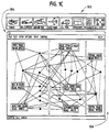
- FIGURE 1C illustrates a user manipulatable main window for the editor.
- Segments may be generated in executable form once they have been defined in the Graphical User Interface, illustrated in FIGURE 1C, using commercially available modeling tools.
- Real-time flight dynamics and models and weapons systems can be developed using a software package, Matrix X (Trade Mark of Integrated Systems Inc.).
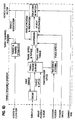
- Matrix X is a commercially available software simulation package used to develop and analyze models of multiple input/multiple output nonlinear systems. This software package allows a user to create models using a graphical user interface. Icons are connected to form block diagrams of the modeled system. The icons represent mathematical operators which the program uses to produce and solve systems of equations. Fig. 1D illustrates a vehicle dynamics segment represented in block diagram form.
- Matrix X provides the analysis tools (such as curve fitting routines, frequency response computation, plotting routines, etc.) needed to develop, analyze, and validate flight dynamics models. After completion of model validation, Matrix X provides the capability to convert the system block diagrams directly to real time software in languages such as ADA or C. This same capability allows the flight dynamics model to be rapidly changed by the user to match future aircraft upgrades.
- analysis tools such as curve fitting routines, frequency response computation, plotting routines, etc.
- the electrical system utilizes an Electrical Interface Device (EID) 24 which provides a minimum update rate of 60 Hz for true real-time simulation. This update rate is especially important for flight vehicle simulators.
- EID Electrical Interface Device
- the modular EID 24 utilizes commercially available components and supports expendability.
- the EID communicates to the host computer 12 through an Ethernet interface.
- FIGURES 2 and 2A illustrate a form of the simulator or training module 30.
- the module 30 is particularized for a specific platform and/or simulation exercise by using one member of a plurality of multi-personality, platform kits K1, K2. . .Kn.
- a common one-person hardware frame or sled 32 is the basic building block for the module 30.
- the frame or sled 32 is associated with an individual operator or member of the platform crew.
- the frame/base structure 32 is designed so multiple vehicle “kits” may be easily mounted on the base to rapidly configure a particular vehicle simulator.
- the frame structure design includes easily assembled/disassembled members. Power and data distribution cables are concealed within the frame's tubular design.
- the frame houses all power, video, and data interface connections.
- Each frame is equipped with free rotating castors for easy transport, and leveling pads for use when in position for training. No component of the assembly requires more than a two man lift. All components break down for easy shipment without major disassembly and pass through a standard 30 inch door.
- the frame 32 includes a seat 34 intended to be used by the individual crew person associated with that particular aspect of that platform. Single crew or multiple crew platforms can be simulated as described subsequently.
- the frame 32 provides a lower region, generally indicated at 36, for receipt of power supplies, electronics, connectors, and I/O interface electronics (the EID) generally indicated at 24.
- the frame 32 provides an upper mounting region 38 to which a heads-up projection display system 42 can be mounted. As an alternate to the display system 42, the operator can be provided with the helmet-mounted display unit.
- the standardized frame 32 can be personalized to a particular platform by use of platform-specific kits such as K1, K2. . .Kn. Kit K1 is illustrated with the sled 32.
- platform-specific kits such as K1, K2. . .Kn. Kit K1 is illustrated with the sled 32.
- K1 provides platform-specific control and displays by using, for example, removable consoles 44a, 44b, which would correspond to the configuration, appearance, and arrangement as expected to be found in the platform being simulated.
- the consoles 44a, 44b are removably attachable to side members 32a, 32b of the frame 32.
- the consoles 44a, 44b are adapted to receive a plurality of control modules indicated generally at 46a and 46b.
- the control modules 46a, 46b removably engage the console members 44a, 44b and are also of a type which would be expected to be found in the platform being simulated.
- the control modules 46a, 46b can include switches, levers, or dials which can be operational, in which event they are in communication with the interface system 24. Alternately, depending on the nature and purpose of the simulation or training exercise, the members of the plurality 46a, 46b could be merely graphical depictions of certain control elements which, are unimportant or irrelevant from the point of view of a particular simulation or training exercise to be carried out.
- the frame 32 can be further configured to exhibit the personality of the platform being simulated by the addition of platform-specific display devices or instruments 48a, 46b which are supported in appropriate orientation and arrangement at the front end of the frame 32 as would be expected for the platform being simulated.
- the devices 48a, 48b could be computer-driven display devices which are intended to simulate actual instruments or displays found in the platform being simulated.
- the displays 48a, 48b could be, for example, flat panel plasma displays.
- the displays 48a, 48b can be coupled to and be in communication with the instrument computer 22.
- the displays 48a, 48b can be driven by channels of the image generator 20 and updated locally by an instrument simulating computer 22.
- a frame 49 supports the displays 48a, 48b.
- a bezel structure 50 of a type which would correspond to the appearance of the instrument panel of the platform being simulated.
- a user located in the seat 34 when looking toward the bezel 50 and the computer-driven displays 48a, 48b, would see a plurality of platform sensors, instruments, gages, and display devices exactly corresponding to those found in the platform being simulated.
- Out-the-window displays 52 are provided by one or more display devices, which might, for example, be flat panel plasma displays, for the purpose of providing to the user a view of a simulated adjacent terrain in which the platform being simulated is located and possibly moving.
- the display units 52 are configured and oriented so as to duplicate the arrangement of the windows, if any, of the platform being simulated.
- the displays 52 are mounted and held in an appropriate orientation by a mechanical framework 54 which is intended to couple to the frame 32.
- the device interface circuitry 24 is in bi-directional communication with the host computer 12.
- the host computer 12 is, in turn, in communication with the hardware display or image generator 20 which presents three-dimensional displays on the display elements 52.
- the system 10 supports a plurality of different image-generation systems which in turn drive a plurality of different display devices of varying fidelity depending on platform requirements and costs.
- system 10 can be used to create both visually and mechanically correct modularly based structures which simulate the appearance and behavior of a platform being simulated.
- Platform controls are provided by platform-specific joy sticks, levers, steering wheels, or rudder controls, generally indicated at 56 which are intended to be releasably coupled to the frame 32. These control elements are all in communication with the interface circuitry 24.
- the module 30 can include additional platform specific hardware not noted above.
- an audio subsystem 30a coupled to communications unit 26, can be used to provide audible cues and realistic vehicle simulation sounds to crew members to enhance the realism of the simulation.
- An electronic warfare subsystem 30b implements the electronic warfare capabilities, if any, of the vehicle being simulated.
- Cockpit module 30c provides additional manually operable cockpit controls including switches, knobs, joy sticks, control levers, and the like which would be associated with the operation of the vehicle being simulated.
- a weapons subsystem module 30e provides weapons-related functionality enabling the user to control or activate weapons of a type associated with the platform being simulated.
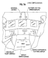
- FIGURES 3 and 3A illustrate a system 60 having a tandem configuration wherein two frames 30-1, 30-2, of the type previously discussed, are arranged to correspond to the cockpit of an AH64A attack helicopter.
- Frame 30-1 has been configured to correspond to the displays and controls for a co-pilot/gunner.
- Frame 30-2 has been configured with another kit to correspond to the controls and displays of a pilot.
- An outer shell covers each crewstation to provide a representation of an enclosure.
- Frame 30-1 has been configured with modules, such as console modules 44-1, 44-2 which correspond to a personality kit for the co-pilot/gunner portion of the AH64A helicopter.
- frame 30-2 carries a personality kit which configures it to conform to the appearance of the pilot's control elements, displays, and gauges of the AH64A helicopter.
- the two sled configuration utilizes a five channel IG which drives the OTW displays and the sensor displays.
- a three channel instrumentation system is used to provide real-time instrumentation within each crewstation. In addition, navigation and radio communication capabilities have been provided.
- the AH64A pilot station kit consists of the front and side console assemblies, including all instruments, switches, and indicators determined to be critical for training.
- the cyclic, collective, and pedal assembly provide realistic simulator controls.
- OTW imagery is provided by either three plasma displays, or a head tracked HMD.
- the simulated sensor video display unit (see FIGURE 6) is a repeat of the copilot/gunner's sensor view.
- the AH64A copilot/gunner station kit consists of front and side console assemblies, including all critical switches, instruments, and indicators.
- the gunners Optical Relay Tube (ORT) is provided, including gunnery switches and controls, a Heads Down Display (HDD) and the Heads Out Display (HOD). Through the HDD, the gunner has the ability to switch between OTW and sensor display. The pilot's OTW view is repeated in the copilot/gunner's crewstations.
- the frames 30-1 and 30-2 would each incorporate a template and a bezel, corresponding to the bezel 50, for the purpose of covering flat panel plasma display 48-1, 49-1, corresponding to the displays 48a and 48b, for example. This will present an optical appearance to the individuals participating in the simulation as the pilot and co-pilot which corresponds to the overall appearance of the interior of the corresponding cockpit.
- FIGURE 4 illustrates for one of the cockpit displays, for example, the display 48b, the use of an overlying template 62.
- the template 62 could be part of, or attachable to, a bezel, such as the bezel 50.
- the template 62 includes a number of cut-outs illustrated generally at 62a which correspond to the instruments and displays of, for example, the AH64A cockpit.
- the computer-generated displays of instruments, gauges, output indicators, and the like, presented on the flat panel display 48b, by means of the template 62 can faithfully replicate the appearance of the corresponding devices that are actually present in the cockpit.
- the template 62 also carries an open region 62b which can be for the purpose of presenting another display of the type which would be found in the respective cockpit. Alternately, the opening 62b can receive a modular control element found in the corresponding aircraft at that location for purposes of replicating the structure which would be seen by one of the crew members in that aircraft.
- FIGURE 5 is a further illustration of template 62 having two sections 62-1 and 62-2.
- the section 62-1 carries the plurality of cut-outs 62a illustrated in FIGURE 4. As illustrated in FIGURE 5, those cut-outs correspond to and frame a plurality of simulated gauges, indicators, and displays 63-4 through 63-16, 63-20 and 63-21.
- the portion of the template 62-2 carries a plurality of control switches and the like including elements 63-1, 63-2, and 63-17 through 63-19.
- Signals received from the control elements 63-1, -2, and 63-17 through -19 can be made available to the host processor 12 via interface element 24.
- the displays presented on the portion of the template 62a are driven from commands produced by the display computer 22 and transferred to the flat panel display 48b.
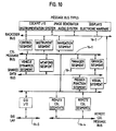
- FIGURE 6 is a block diagram illustrating various aspects of one implementation of the system 60 where each of the crewstations 30-1 and 30-2 has associated therewith its own host processor 12-1 and 12-2.
- the host processor 12-1 in turn provides signals to drive image generator 20.
- Host 12-1 is also in bi-directional communication with instrument display processor 22-1 which is used to generate and to update the real-time instrument display, such as the display 48-1, illustrated in FIGURE 5, of cockpit indicators and instruments. These images can be replicated on station 2, display 48-2.
- the system design incorporates commercial components and commercial interface standards to minimize cost and provide maximum expendability. Using commercial components and an architecture consisting of well-defined system modules, the design provides for ease of fault detection and isolation, interchangeability, and replacement of parts. The modular system design also allows future expansion for new vehicle kit configurations, and incorporation of new technologies with minimal non-recurring cost.
- a UH-60 utility helicopter configuration 80 is an alternate simulatable vehicle.
- This system includes two modular sleds 82a, 82b, placed in a side by side configuration, as illustrated in FIGURE 7.
- the sleds 82a, 82b are identical to the sleds 30-1 and 30-2 of FIGURE 3. They are particularized for the UH-60 platform by two UH-60 vehicle kits and a common control console 82c.
- a copilot observer kit is mounted on the left sled 82a, while a pilot station kit is mounted on the right sled 82b.
- the center instrument console 82c is mounted between the two stations.
- An outer shell or bezel covers the entire cockpit to provide a representation of the actual enclosure.
- the two sled configuration requires one five channel image generator to drive five OTW displays 84a.
- Real-time instruments are provided using a three channel instrumentation system 84b.
- a communication and navigation system are implemented. In this configuration, either the copilot observer of pilot may assume control in real-time.
- the pilot and copilot observer stations in FIGURES 3 and 7 have common characteristics that grow out of a modular approach. Both stations are complete with front and side consoles, including all switches, indicators, and instruments required for training. Each crewstation contains collective, cyclic, and pedal controls to provide either station the ability to fly.
- FIGURE 8 illustrates further details of the common central console 82c.
- the console 82c is supported on a multi-element frame. While not shown, the upper surfaces of the console, indicated generally at 86a and 85b, can be filled with modular, manually operable control elements and gages, displays, or meters of a type which would normally be found in the UH-60 platform.
- the three channel instrumentation system 84b having display elements 84b-1, 84b-2, and 84b-3, illustrated in FIGURE 8 is covered in part by a template 86 which corresponds to the shape, arrangement, and appearance of instruments, gages, dials, and read-out devices normally found in the cockpit of the platform.
- a template 86 which corresponds to the shape, arrangement, and appearance of instruments, gages, dials, and read-out devices normally found in the cockpit of the platform.
- the use of templates, such as template 86 results in realistic looking read-outs and gauges of a type that would be found in the subject platform.
- the template 86 includes openings 86a, 86b which could be filled with modular switch/control elements again replicating those found in the subject platform.
- FIGURE 9 illustrates a gunnery configuration 90 based on a modular sled such as the unit 32.
- the system 90 includes a supporting sled 92 which, in turn, supports gunnery display and associated controls 94.
- An additional display 94a is disposed somewhat to the right of the operator's position, as would be the case with the platform being simulated.
- gunnery related control elements 94b are also carried by the sled 92.
- the system 90 incorporates a single kit for purposes of personalizing the sled 92. It will be understood that a plurality of sleds, such as the sleds 92 could be linked together to provide three crewstations for a land vehicle such as a tank. In addition to providing the appropriate displays and vehicle interactions, in such an arrangement the crew members would be in communication with one another as would be the case in the subject platform.
- a configuration file for a particular platform to be simulated includes a plurality of object oriented segments, such as segments 18, which are independently executable. Those segments which implement elements of a platform class may be interchangeable. For example, the vehicle dynamic segment or the weapon segment for one type of platform can be replaced by corresponding segments from another platform. Similarly, the manager and environmental segments might also be interchangeable between platforms.
- the individual segments distribute messages throughout the virtual network 16a which is implemented by CSL 16.
- the CSL 16 provides various types of services to application segments such as application generic service calls.
- the services calls access the operating system, the interprocessor communication system, shared resources and also provide tasks scheduling.
- the process of creating an executable control program for carrying out a simulation of a selected platform first requires that a configuration file be created. Either a new file can be created or an existing file can be edited or modified using the configuration file editor via the associated graphical user's interface, main window of which is illustrated in Figure 1C.
- the configuration file specifies the segments and interconnecting messages which ultimately carry out the control process leading to behavior which simulates the selected platform.
- a configuration file includes a manager segment. The manager segment issues a loud configuration call. The configuration file is then read in the segment executable so called. The called segments in turn issue enter configuration calls to register with the CSL 16. They then initiate various generic procedure calls to access message data. When the segments are all initialized, the simulation process can begin.
- the tasks of the various segments are synchronized on either clock pulses and/or message events.
- Each of the messages is in effect a multiple bit bus for registered segments associated with that message. Segments which write or publish to the bus or segments which read or subscribe to the bus are registered segments.
- a CSL message bus 16-1 provides intersegment communication within a host processor 12.
- a group of buses which are associated with input output devices on the sled 30 indicated generally at 16-2, which can be implemented as either RS232 serial ports, Ethernet ports or other types of input output communications paths are used for coupling hardware on the sled 30 to the respective hardware related segments.
- An internal shared data bus 16-3 is implemented as an unprotected and unbuffered memory.
- Communication to other processors on the virtual network 16a can be implemented using remote message buses 16-4. To the extent that the system is coupled to a DIS simulation network, that network can be accessed via an external bus 16-5.
- Segment types include object module segments which are application level segments which provide or hold data pertaining to functional characteristics of a selected vehicle. These include vehicle dynamic segments, vehicle propulsion segments, weapons segments, an environmental segment and a manager segment. Support class segments are those which provide data to the object module segments and include the mission function segment and the visual segment.
- the lower level hardware interface segments are characterized by having back door buses which provide access to hardware on the sled 30 which might be through the image generator 20, the instrumentation display computer 22 or the electronics interface 24.
- the network interface segments facilitate communications between remote processors such as 12-1, 12-2..12-n or a DIS network.
- Messages which are areas of data which are written to and read by segments have a number of parameters. Each message has a name associated therewith. The message name is used in CSL calls to distinguish between different messages.
- each message is specified as a number of bytes required for a buffer to hold single message.
- a buffer factor parameter defines how many instances of a particular message can be stored or saved at one time.
- a protect flag parameter controls message access. Read/write access to a message can be enabled or disabled using this parameter.
- An X position parameter and a Y position parameter are used by the configuration editor graphical user interface to specify the X and Y positions of a given message on the screen.
- Segments have associated therewith a plurality of parameters. Each segment is named. The segment name is used by CSL calls to distinguish between different segments used in a given simulation. A host parameter specifies which processor or processors the segment should run on. In the case of a manager segment, in normal operation that segment would be executed on all hosts used in a given simulation process.
- a particular processor can be specified to which a given segment will be associated. Absent binding a segment to a processor, CSL 16 and the operating system may move a particular segment to a different host for execution.
- a path parameter specifies a UNIX path for the segment executable or script file that will run the segment executable.
- a priority parameter controls the priority that the segment will receive relative to other processors or segments being run on the host.
- a lock parameter makes it possible to lock a segment's text and data area thereby making it immune to routine swapping by the operating system.
- a list of message names must be provided along with the type of access to indicate those messages that the segment needs access to.
- X and Y position parameters for the configuration editor graphical user interface must also be specified.
- a configuration file can be implemented as a text file.
- a configuration file can be edited using a configuration file editor having a graphical user's interface.
- An exemplary configuration file is attached hereto as Attachment A.
- Configuration files specify in effect what is a two dimensional graphical representation or functional flow diagram of the simulation process.
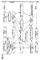
- Fig. 11 illustrates, graphically in a two dimensional formation, the configuration file attached hereto as Attachment A.
- segments are illustrated as rectangles.
- Messages, which provide communications between segments are indicated within somewhat oval shaped symbol.
- the graphical representation of the configuration file of Attachment A is illustrated in Fig. 11, lends itself directly to graphically based editing using a configuration editor module.
- Editing can take place via the instructor's counsel.
- the editing process makes it possible to change the characteristics or the behavior of the platform being simulated between simulation runs simply by carrying out an interactive editing process.
- vehicle or platform dynamics can be modified, weaponry can be altered or propulsion systems can be changed.
- a new heretofore unbuilt platform can be specified in a configuration file.
- An appropriate kit or kits can be created and mounted on one or more of the sleds 30 for the purpose of simulating the operation and behavior of the new platform.
- Characteristics of the platform can be modified using the configuration file and its graphical user's interface in between simulation runs to vary parameters of the proposed platform.
- the platforms control characteristics is propulsion system, or its dynamics can be modified in an attempt to achieve an optimal combination of characteristics prior to ever attempting to build the respective vehicle.
- FIGURE 1C illustrates a main window display of a particular configuration file as presented to an instructor or a user by the configuration file editor. Segments again are indicated in rectangular boxes. Across the top of the display is a configuration file type selection window 102. A user can select a particular type of configuration file by clicking on the selected type of platform. Additionally, six menus are specified at a region 104.
- Selecting the file menu presents the following options: “open” opens a file system browser so as to select and open an existing configuration file; “new” displays a prompt for a new file name and opens a new configuration file with that new; “save” saves the current configuration file under the name assigned to it; “save as” will provide a prompt for a new file name and save the current configuration file under that name; “close” closes the currently open file and prompt the user to save if any changes were made in the file; "quit” ends the configuration file editor.
- the main window also displays the current segments and messages in the selected configuration file, along with their connectivity, in a region generally indicated at 106.
- the configuration file illustrated in Fig. 1C is that of a vehicle corresponding to a tank.
- the characteristics of the vehicle illustrated in Fig. 1C can be modified or revised.
- the revised segments can then be recompiled.
- the compiled segments corresponding to the revised vehicle can then be executed, in combination with a sled, such as a sled 30, which has been modified with a tank kit to correspond to one of the crew positions of the selected tank.
- a user can modify the interconnected graphically displayed configuration file. Either segments or messages can be modified or edited.
- FIG. 1D illustrates the dynamics segment for a tank, illustrated in Fig. 1C, opened for modification.
- the segment is presented in block diagram form in a way that a designer or an instructor would be able to carry out graphical revisions to or modifications of the segment.
- Each of the blocks illustrated in Fig. 1D could be called up individually and modified as required so as to adjust the dynamics of the tank.
- a dynamics segment for a different model tank could be imported into the configuration file illustrated in Fig. 1C from another, prestored, tank configuration file in the system. This makes it possible to quickly move model object segments from one platform to another model of the same general type of platform for comparison and study purposes.
- the segment can be saved. Any other segment can be revised or modified accordingly.
- the simulation algorithm or methodology can be revised in between runs to take into account new vehicle characteristics to be explored or new or different functionality to be added to a known vehicle.
- a connect option makes it possible to make a connection between a selected message and a selected read or write port or box of a segment.
- a delete function will delete all selected objects segments messages or connection lines.
- An add segment capability presents a window to enter the properties of a new segment and then display the segment box on the main window. Once displayed the new segment can be positioned appropriately. Subsequently, messages can be added by an add message feature. The user will be presented with a window for entering the properties of a new message. The message logo will be displayed on the window and can be moved to an appropriate position linking segments.
- Other editing capabilities as would be known and understood to those of skill in the art can be provided.
- the view member makes it possible to access model information, change the size of the main window to adjust the amount of marginal white space and provide a monitor window which will provide an estimate usage summary.
- the options menu provides an ability to select a processor upon which a given segment is to run.
- the print menu provides an ability to print various items including segments, messages, can activity information as well as host information.
- the control menu can be used to run or shut down a simulation.
- Configuration files for new or modified vehicles can be created from existing segments and configuration files.
- a tool bar 102 will be displayed illustrating a configuration file types present in the system.
- Each of the illustrated symbols represent working configuration files that are stored for recall.
- a supplemental window will appear, see Fig. 12, which presents icons representing those configuration files for vehicles that correspond to the selected type of vehicle.
- the configuration file for this vehicle will then be loaded into the main window 106 as in Fig. 1C.
- Additional prestored segments can be added to the configuration file being displayed by selecting the "segment" icon which in turn will display a window as in Fig. 13. Segments from the window in Fig. 13 can then be dragged into the main window, Fig. 1C and message connections can be made thereto as appropriate. In addition, the newly added segment can be revised or edited as described above. Subsequently, the configuration file can be processed and compiled into executable form and the simulation executed.
- modules 46a and 46b could be implemented as hard wired interconnections of various electromechanical and/or electronic elements.
- one or more of those modules could include a programmed processor coupled to associated control elements such as switches or dials as well as instrument readouts, or simulated readouts, for the purpose of implementing the desired function of that particular module.
- the local processor in the module can be driven by locally prestored instructions or data.
- the host 12 could transfer some or all of the instructions and data via the electronic interface 24 to the respective local processor for execution. Similarly, that processor can transfer data back to the host 12 for analysis and to respond to actions of the various crewmembers.
- Attachment B provides additional information concerning the structure and use of segment and message elements as described previously.
- the Reconfigurable Simulator software consists of several indepentently executing but integrated segments. Segments may be configured to run on separate processors on a particular machine or on separate machines entirely in order to maximize available computational capabilities. The segments interact through predefined messages which are shared memory locations that are controlled by the CSL.
- the Control Segment is responsible for getting user input from hardware devices (as well as software-simulated devices) and making it available to the rest of the simulation in the form of a message and outputting data to the hardware.
- the control segment is reading a flybox, the process becomes I/O bound. Trying to time the execution is less straightforward than other segments. Actual CPU usage is computed for statistics reporting.
- This segment should also be the real-time user interface into the simulation. Viewpoints, entity attachments, and ownship beaming modifications should be accomplished through a graphical user interface.
- control segment is general in nature in that it is responsible for I/O, various type of hardware can be used in the simulation.
- a flybox or the EID PC are used for vehicle I/O.
- the EID PC is a rack mounted PC that sits in the sled of the reconfigurable system. It interfaces to an ADAC unit to process I/O and sends the data the RHS via ethemet.
- the DIS PDU I/O segment is responsible for receiving and transmitting Protocol Data Units (PDUs) across the simulation network. It converts DIS PDUs to UDP ethemet packages and sends them to the DIS network. It also monitors the network for DIS PDU traffic and writes messages to the other segments when a valid PDU is encountered.
- PDUs Protocol Data Units
- the Environment Segment is responsible for all remote PDU processing. Its primary responsibility, however, is processing remote entities via Entity state PDUs. If an entity is new, the Environment Segment will request that the model be loaded by the Visuals Segment, and that terrain following results be returned by the Mission Functions Segment. Otherwise, the existing model is updated. Models which are not updated from entity state PDUs are dead reckoned using previously specified attitudes, positions, and velocities. Since the number of entities to handle can become overwhelming, range and field of view are used to prioritize the entities. As many entities that can be processed within the time allotted are then moved based upon their prority. Low priority vehicles can still be processed using a time out counter.
- the Instrumentation Segment processes all the data to be sent to the instrumentation PC. It reads data from various segments, performs any necessary byte swapping (refer to Section 6 Instrumentation Operation), and then assembles raw ethernet data packets to be sent to the Instrumentation PC.
- the Manager Segment begins the simulation by informing the core services of the current system configuration and then starting the segments.
- the manager segment can take the optional command line arguments -spawn/-nospawn and -clock ⁇ clock cycle>.
- the -spawn option which is the default if no -spawn/-nospawn is given, is used to tell the CSL to automatically spawn (or start) the segments. If the -nospawn argument is given then all the segments in the simulation must be manually started by the user.
- the -clock argument can be used to generate timing if the Visuals Segment is not being used (this is primarily for debugging purposes).
- the Manager Segment is also responsible for gathering timing information from all other segments and calculating CPU loads and informing the segments of their allowable run time. For more information on this time management see the section on Load Management.
- the Missions Functions Segment is responsible for computing mission functions. These include terrain following for both ownship and remote vehicles, ownship collision, line-of-sight, and projectiles.
- This segment may use the image generator (IG) to perform some mission functions by interfacing with the Visuals Segment.
- IG image generator
- the decision to use the IG is based on the load constraints placed on the segment, improved accuracy that the IG might provide, and time constraints.
- the Mission Function Segment performs the following functions: (1) read visual messages, (2) read mission function request messages, (3) read IG results, and (4) process current mission function definitions.
- the Mission Function Segment will keep track of models and their positions by reading the Visual Action messages sent to the Visuals Segment. All other messages to the Visual Segment will be ignored.
- Mission function requests can be definitions, updates, or terminations. Definitions request that the Mission Functions Segment return results at a frequency specified in the definition. Definitions require that the model be loaded that the mission function is associated with. The mission function may be handled by the segment or by the IG. Updates allow some data associated with the mission function to be changed (e.g. a projectile position). Terminations cancel a mission function.
- Results read from the IG are basically returned to the requesting segment without much interaction by the Mission Functions Segment.
- the segment does determine which result message buffer to put the result in (either ownship or remote moving model).
- Processing mission functions can be computationally expensive. To alleviate this potential problem, subcycling is performed. Definitions require a frequency to be given for each mission function. Defining mission functions with a frequency less than every field can help avoid overloading the segment. In any event, the segment will only perform as many mission functions as it predicts it can, and might run the mission functions at a much lower frequency than requested. Handling some mission functions on the IG can reduce the load. This adds a latency in the resuits. Ownship mission functions are always given priority over remote moving model mission functions.
- the Navigation Segment is responsible for updating instruments corresponding to the navigation of a helicopter. This includes such instruments as the Doppler navigational unit. It reads inputs from the hardware and state information about the ownship helicopter and performs the logic in order to update navigational equipment.
- the Vehicle Dynamics Segment performs all the processing for the ownship model. During initialization, the segment requests that the ownship model is loaded and that terrain following and collision mission function results be retumed. It also communicates to the weapons segment the state of the vehicle so that proper ballistic solutions can be computed. During normal execution, the segment computes the vehicle's current state vector by accepting input from the Control Segment and integrating the math model with the appropriate time step. Dead reckoning and heartbeat functions for the ownship, requirements of the DIS protocol, are handled by this segment and PDU messages are sent to the DIS I/O Segment if necessary.
- the basic requirement for the math model is that the vehicle should have discemible parts which accurately simulate the operation of the vehicle in question.
- this includes the engine, transmission, ground interface, suspension, auto pilot, barrel control when necessary, and equations of motion to compute the output state vector used by the segment.
- Rotary wing flight vehicles will require the engine, auto pilot, main rotor and tail rotor models, aerodynamic performance characteristics, suspension, ground interface including ground effects, and equations of motion to compute the output state vector used by the segment.
- the math model should be designed and generated by some form of graphical modeling tool so that updating and testing the vehicle dynamics can be done in a user friendly and thoroughly commented environment. The code that will be generated by this tool should be easily interfaced into the vehicle dynamics segment with minimal effort from the user.
- the graphical modeling tool should be accessible through the Core GUI so that the user will not have to enter a command line environment.
- the autopilot should be able to accept a table of waypoints that include the point in space, a desired approach velocity, and a pause time when the vehicle has reached the waypoint. It should also be able to be reset and turned off and on at will. Other operations such as enfilade and defilade maneuvers should be able to be performed at any time during a waypoint table traversal. These autopilot characteristics should be valid for all types of vehicles.
- the waypoint table must be provided in an ASCII text file with the following format using floating point numbers:
- the last line tells the segment that there are no more waypoints to be read. There is a limit of 50 waypoints that can be input through a waypoint table.
- Control Segment there are individual vehicle dynamics segments depending upon the confguration being run.
- the currant vehicle dynamics available are for the AH64, UH60, and M1A2.
- the dynamics for the vehicle may be different, the messages read and written should be the same. This allows for quick reconfigurability by simply replacing one dynamics segment with another.
- the Visuals Segment processes all requests needed of an IG. These requests include model loads and unloads, model position and attitude updates, viewpoint updates, special effects activation and deactivation, and missions function requests. It is also responsible for receiving the IG interrupt for timing and informing the core services so that the other synchronous segments can run.
- the visual messages should be generic in nature so that a Visual Segment for one type of IG can be easily replaced with a Visual Segment for another IG.
- the Weapons Segment is responsible for computing the projectile ballistics and ballistic solution for the vehicle being simulated.
- the basic functionality of the segment is to read the proper inputs from the user and vehicle, compute a ballistic solution, fire a projectile or guided munitions, maintain a list of airborne projectiles, and detonate the projectiles on impact with the database or another moving model. It is also responsible for generating the firing and detonation PDU messages to be sent to the DIS I/O Segment.
- the two vehicles with weapons that are currently being simulated, the M1A2 MBT and the AH-64A Helicopter employ a Fire Control Electronics Unit(FCEU). This segment is effectively acting as the FCEU in order to assure proper behavior of the weapons system being simulated. This requires that the segment be effectively linked to the vehicle dynamics, environment, and mission functions segments.
- the math model that is used to simulate the above requirements should be designed and generated by a graphical modeling tool so that updating and testing the weapon system dynamics can be accomplished in a user friendly and thoroughly commented environment.
- the code generated by the modeling tool should be able to be easily interfaced into the weapons segment with minimal effort from the user.
- This message contains PDUs to be processed by various segments.
- This message contains PDUs to be output to the network.
- This message contains data to be processed and sent to the instrumentation PC.
- Mission functions can be defined to be one-shot (i.e. executed once) or continuous.
- This message contains remote model mission function results (typically terrain following).
- This message contains inputs from the hardware corresponding to navigational equipment.
- This message contains actions for the ownship to take, primarily when it is in Simulation Management (SIMMAN) mode. This includes such actions as create/remove, reconstitution, stop/start, and data query.
- SIMMAN Simulation Management
- This message contains ownship mission function results (terrain following, collision, line-of-sight, and projectile).
- This message contains a processing time limit that each segment on a processor will apply to its load. A duration is also specified until the next load management analysis takes place.
- the message contains data about all the entities in the current simulation, both ownship and remote.
- This data includes such information as position, orientation, and velocity. It is a ping-pong array of data that is read from the ping side and written to the pong side during even frames and vice versa during odd frames. It is an unprotected message which allows all segments that need access to entity information to make one request at the beginning of the simulation for the data. This allows quicker access to the data and hence, minimizes the overrun of execution time since the number of entities can be large.
- This message contains load management information.
- the mission function segment and the environment segment use this information in order to control the work load.
- the message can contain (1) viewpoint position and attitude, (2) viewpoint field of view, (3) filtering range, or (4) maximum wait count.
- This message contains timing statistics for each segment. The information is used by the Manager Segment to perform load management.
- This message is similar to the Input PDU Message in that it contains data related to input PDUs. However, instead of being formatted like a PDU it simply contains unformatted data that holds the necessary information related to a particular type of PDU. Therefore, if the format of a PDU changes but the data in it remains the same then this message does not have to be changed. In the future this message should completely replace the DIS Input Message.
- This message is similar to the Output PDU Message in that it contains data related to output PDUs. However, instead of being formatted like a PDU it simply contains unformatted data that holds the necessary information related to a particular type of PDU. Therefore, if the format of a PDU changes but the data in it remains the same then this message does not have to be changed. In the future this message should completely replace the DIS Output Message.
- This messages contains the digital and analog data read from the hardware.
- the message contains digital and analog data to be output to the hardware.
- This message is responsible for communicating information about the ownship's current state to the weapons segment. Included in this message is the vehicle's position and orientation of the hull and articulated parts, the database being used, PDU update information, gunner's sight orientation, and a flag which indicates whether or not the barrel has incorporated the ballistic solution's offset commands indicating that it is ready to fire. It is updated every field by the vehicle dynamics segment and is read by the weapons segment whenever a projectile fire request has been processed or when the user requests that a ballistic solution be computed.
- This message is an "all-purpose" message read by the visuals segment to perform a variety of visual functions. These functions include model loads, unloads, and updates, viewpoint updates, special effects activation and deactivation, and mission functions.
- This message retums mission function results computed by the IG (Visuals Segment) to the Mission Functions Segment for proper bookkeeping.
- Segments in this system are categorized as asynchronous or synchronous, and fixed-load or variable-load.
- DIS I/O Segment In the DIS environment, components of the simulation are intended to be asynchronous. However, in order to insure correctness, some synchronization may be necessary.
- DIS I/O Segment and Control Segment Other segments need to be executed every field: Vehicle Dynamics Segment, Environment Segment, Instrumentation Segment, Mission Functions Segment, Navigation Segment, and Visual Segment.
- the Manager Segment will be responsible for gathering statistics on all maintainable segments and providing feedback to the segments so that each segment can manage its load.
- Each segment will be categorized as having a fixed-load or variable-load execution.
- a fixed-load segment cannot do much about controlling its execution time.
- the Control Segment may fall in this category.
- a segment of this type has one unit load and an associated execution time.
- a variable-load segment has multiple units of work to process. In many instances it may be possible to prioritize the units so that important units are processed first when all units cannot be processed in one field.
- the Environment Segment and Mission Function Segment fall into this category. Models which are far away or are not visible may not need to be positioned or require terrain following results. Such tasks can be postponed to a more opportune time.
- Each segment will also be classified as being either asynchronous or synchronous.
- a synchronous segment will run every field.
- An asynchronous segment has no definable schedule. So, only synchronous segments are guaranteed to report statistics to the Manager Segment when they are supposed to.
- Each segment will be responsible for collecting its own statistics. At some appointed time, it will send a message to the Manager Segment detailing its load type (fixed vs. variable), synchronization type (asynchronous vs. synchronous), number of units of work, and execution time per unit of load. A segment with different types of work may have to normalize its different measurements.
- the Manager Segment will send a message specifying how much load the segment can operate on and still safely finish within the field. It is advantageous that the message also detail when statistics should be sent again. If a segment's load varies during this interval, it must not go beyond the limit established from the last analysis. Falling below the reported load will result in idle time within the field and will prevent another segment from doing more work.
- the Manager Segment will bookkeep each segment's load and execution time.
- the Manager Segment will gather statistics messages until all synchronous segments have sent them.
- An asynchronous segment cannot guarantee that it can report its statistics at the appropriate time, but its data are used if reported before the last synchronous segment. If no new data are present for a segment, old data are used. This fact must be reported back to the tardy segment. Since this is likely to be a recurring problem, it is advantageous that an asynchronous segment report its statistics early.
- a weight is sent in a message to the appropriate segments.
- the responsibility falls upon the segment to manage its load according to the returned weight. Also, the Manager Segment will tell the other segments how long to gather new load data before it computes a new weight. Dunng this time, the segments are locked in on the old load.
- Each segment must determine its load and execution time. This can be an average, a maximum, or some other estimate. Using a maximum might result in idle time at the end of a field if a segment does not maintain this load. An average may provide a good measure in the long term, but some other estimate may be necessary if the average load is small for some period. In any case, these decisions are made on a per-segment basis and will not affect the design of other segments (but they will affect performance).
- the primary goal in load management is to attempt to guarantee high priority functions are handled first (e.g. ownship position/attitude updates, weapons functions).
- This section describes how to run the RHS from both the command line or from the core services GUI (Core GUI).
- the source code for the RHS is located in /proj/sim2000/baseline.
- An executable version of the RHS is located in /proj/sim2000/runbase.
- the following files should be present in the directory that the simulation will be run out of:
- sim2000_setup.script in the scripts directory should be 'sourced' before running by typing "source sim_setup.script interactive”. This file will set up the appropriate environment variables end will also look for a setups/ ⁇ hostname>.setup file that sets up host specific environment variables.
- the simulation is started by running the manager_main program.
- the manager_main expects at leat one input, which is the system configuration file and can be given any name, usually having a .cfg extension.
- the manager_main accepts the option to spawn or not to spawn the segments and can be specified by the -nospawn or -spawn switches. The default is to spawn the segments. If segments are spawned, then the core services will look in the configuration file for the path name of the segment. Currently, for each segment there is a shell which runs each segment in its own xterm window. Output is redirected to a file ( ⁇ segment_name>.out) while also being viewed in the window via the tee(1) command. If segments are not spawned, then the user must run each one separately. The simulation is stopped by ⁇ ctri-C> in the manager_main window and then running the shutdown command. shutdown frees the shared memory allocations and semaphores.
- the following is a step by step example of how to bring up the Core GUI, modify a dynamics segment, and run the RHS.
- the configuration that will be used is the ah64_eid.hel.cfg which uses the reconfigurable hardware in an AH64-A configuration. For example purposes, we will use the IVACC database of northern Alaska.
- This section describes how the weapons and dynamics segments are created and generated via graphical modeling tools.
- the weapons and dynamics segments of the RHS have been modeled using graphical system analysis tools that have code generating capabilities.
- the preliminary model build-up and testing is completed in the design environment of the analysis package.
- the user can invoke the code generator to link the model into the appropriate segment.
- the code that is generated handles the math associated with the model dunng each time step or frame.
- the math model is executed more than once every frame.
- the vehicle dynamics models will be run at 60 Hz while the simulation is running at 30 Hz. Hence, for every simulation frame the dynamics model is integrated twice.
- the analysis packages are graphical design tools that allow the model to be built and tested using engineering block diagram representations of the models.
- the models themselves describe the systems of the vehicle or weapon system using hierarchical modeling structure. This ensures that the model is readable and can be broken down and built up in manageable sections instead of the basic building blocks that the tools provide.
- a basic understanding of control systems and logic design is required to effectively build and understand the structure and operation of each model.
- the segments currently built using this method are:
- Easy5x is the analysis tool originally used to adapt code generating capabilities to the host. It only generates FROTRAN code and a few things need to be performed on the resulting code in order to link it into the segment. Segment generation is currently an automated process that is invoked through the Easy5x design environment. This section will explain how to bring up Easy5x and to generate a segment using the available tools.
- the contact at Boeing is Howard Lohr. He can be reached at 212-865-3302 for technical assistance.
- Type 'easy5x &' in the directory of the model that you are working on and follow the instructions in the easy5x manual. You can perform non-realtime simulations to design the system and the instructions for that are in the manual. When you are ready to create the segment code select 'realtime mode' under the 'options' menu. Control-B will start the code generation process by executing the 'ez_rt_build' script in the EZ_RT_DIR directory and execute the appropriate script for segment generation.
- the files used in segment generation include:
- Control-T is the final command.
- This will create the ⁇ model_name>.dyn parameter file that is used at runtime by executing the 'ez_rt_anal' script in the EZ_RT_DIR directory. All of the changes that you make using these methods will affect the baseline configurations. Therefore, if you wish to make experimental changes you will need to create your own directory with the appropriate files in order to not corrupt the base!ine. If only parameter changes are made then the segment does not have to be regenerated. You will only need to recreate the ⁇ model_name>.dyn file. Changes that require regeneration include adding or removing a block from the model or changing the connectivity of the model.
- MatrixX is also a system analysis package but with a few significant differences. This package is much more suited to performing complex mathematical analyses on the system being evaluated. There are more tools and versatility as far as off-line simulation and model generation are concerned. It also has the ability to generate Ada and C code that can be used in the generation of the RHS segments. This section will explain how to bring up MatrixX and generate a segment using the package's environment. The contact at Integrated Systems is Gerry Clarke. He can be reached at 407-857-5790 for technical assistance. MatrixX version 5.0 is the current version which is being used to generate all vehicle and weapon dynamic models.
- Type xmath& in the directory where the model which you wish to modify resides This will bring up a small window with several canvas areas and a typical menu across the top.
- Select File - Load This will open a file browser with all available files shown. Select the desired model. Once loaded, a wide menu bar will be displayed with the File and Build options not greyed out.
- Select Build - Catalog This will open a window displaying all available models and submodels which exist within the model loaded from the Xmath window. If the overall model name is known, select that name. This will cause the current widow to enlarge, displaying the selected model. Read the MatrixX and Xmath user's manuals to learn how to correctly manipulate the existing model or create new models.
- each of the segments has three options associated with them: Property, Parameters, and Processors. These can be accessed by placing the mouse over the segment and pressing the right button. Choosing the Parameters option on the dynamics or weapons segment will start up the appropriate systems simulation design package.
- the segment generation and off-line simulation capabilities of the software packages are now available to the user as if s/he were to start Easy5x or MatrixX from the command line environment. There are three files needed for this procedure to operate correctly:
- the ⁇ segment_name> param file has a line in it that runs the appropriate *.run file depending on which modeling package was used to model the dynamics.
- the DIS/Sim2000 lab is configured to have access to three different areas of the facility for image generator use. These are the Mission Rehearsal lab, the AGTS IG Test Lab, and the DIS/Sim2000 lab. There is ethernet and video access to all of these areas through the fiber optic tower in the lab.
- the ethernet connection into the host computer should be a dedicated line that has had its transmit and receive lines swapped.
- the host computer must have at least a second ethernet port through which the visual segment of the RHS communicates to the image generator (IG). This second port (usually le1) must be configured to be on a subnet different than that of the main ethernet port (usually le0) in order to prevent misrouting of the IG update packets.
- the host is on the DIS subnet (le0).
- the two subnets currently being used for the IGs are the AGTS subnet and the Mission Rehearsal subnet.
- the IP addresses that are valid for these subnets can be found by executing the following command: ypcat hosts > host_table. Edit host_table and find the subnet breakdown.
- the RHS system requires at least 3 out-the-window channe!s and a sensor channel for the TIS on the M1A2 gunner station and the FLIR for the AH64 or five out-the-window channels for the UH60.
- the plasma displays require separate vertical and horizontal syncs and the smaller CRT monitors use composite sync.
- help file for the IG setup. It can be executed by going to /proj/sim2000/help and typing ighelp. Execute the file and enter the choices for the IG in use. The output describes the step by step process for bringing up the IG.
- An SE reference manual is located in the DIS/Sim2000 lab for operation of the Operator Interface Control (OIC) for the IG. To load a database execute the following commands in the OIC:
- the instrumentation for the RHS system is generated by a system developed by Terabit (now owned by Evans & Sutherland) which is housed in a PC. Update information is sent to the PC over a third ethernet port on the host computer. The PC will generate its own video which can then be routed to the reconfigurable system's instrumentation displays.
- the RHS broadcasts instrumentation data over a dedicated ethemet line which is picked up by the PC via raw ethernet packets.
- the third ethernet port (currently qe2) must be on a different subnet than the other ethernet ports in order to avoid misrouting of instrumentation update packets.
- the Terabit hardware is capable of generating three independent channels of video.
- one channel is used for traditional system instruments, the second is mixed with IG video for a neads up display (HUD), and the third channel is unused.
- HUD neads up display
- M1A2 instruments one channel is used for GCDP instruments, the second channel is mixed for reticle generation, and third channel is unused.
- UH60 all three channels are used for traditional system instruments.
- the commands to turn on the mixer are done in the autoexec.bat file in the instrumentation PC.
- Pressing T will put the system in Edit Mode.
- the cursor will start out in the first channel so if you want to make any changes to the instrumentation displays you will need to switch channels by pressing C.
- a cursor and icon bar will appear in one channel.
- the I, M, J. and K keys are used to move the cursor around the display.
- To modify and object position the cursor over the object, press the key for the desired action, and then press the space bar to select the object.
- the user would move the cursor over the gauge, press T and then the space bar.
- the gauge can now be moved around the display. When satisfied with the new position, press the space bar again to deselect the gauge.
- Each option functions in a similar manner to Translate.
Landscapes
- Engineering & Computer Science (AREA)
- Theoretical Computer Science (AREA)
- Business, Economics & Management (AREA)
- Physics & Mathematics (AREA)
- Educational Administration (AREA)
- Educational Technology (AREA)
- General Physics & Mathematics (AREA)
- Aviation & Aerospace Engineering (AREA)
- Computer Hardware Design (AREA)
- Management, Administration, Business Operations System, And Electronic Commerce (AREA)
- Automobile Manufacture Line, Endless Track Vehicle, Trailer (AREA)
Abstract
Description


- Messages read:
- Processing Time, Vehicle Output, Visual Result
- Messages written:
- Instrumentation Data, Navigation Data, Ownship Action, Time Stats, Vehicle Data, Visual Action
- Messages read:
- DIS PDU Output, Processing Time, Unformatted Output PDU
- Messages written:
- DIS PDU Input, Time Stats, Unformatted Input PDU
- Messages read:
- DIS PDU Input, Moving Model Mission Function Result, Processing Time, Shared Data, System Into, Unformatted PDU Input, Visual Result
- Messages written:
- DIS PDU Output, Instrumentation Data, Mission Function Pequest, Ownship Action, Shared Data, Time Stats, Unformatted PDU Output, Visual Action
- Messages read:
- Instrumentation Data, Processing Time
- Messages written:
- Time Stats
- Messages read:
- Time Stats
- Messages written:
- Processing Time
- Messages read:
- Mission Function Request, Processing Time, System Info, Visual Result
- Message written:
- Moving Model Mission Function Result, Ownship Mission Function Result, System Info, Time Stats, Visual Action
- Messages read:
- Navigation Data, Processing Time, Shared Data, System Info
- Messages written:
- Instrumentation Data, Time Stats, Vehicle Output

- Messages read:
- Ownship Action, Ownship Mission Function Result, Processing Time, System Info, Vehicle Data
- Messages written:
- DIS PDU Output, Instrumentation Data, Mission Function Request, Shared Data, Time Stats, VHD Data, Visual Action
- Message read:
- Processing Time, Shared Data, System Info, Visual Action
- Message written:
- Shared Data, Time Stats, Visual Result
- Messages read:
- Ownship Mission Function Result, Processing Time, Shared Data, System info, VHD Data
- Message written:
- DIS PDU Output, Instrumentation Data, Mission Function Request, Shared Data, Time Stats, Visual Action
| Environment Variable | Description | Values |
| CIO_DEBUG | Turn on debugging for CSL configuration I/O | True/False |
| CSL_REMOTE_SPAWN | Remote spawn segments | True/False |
| DATABASE | Name of the database being used | alaska, bayou, desert, france, hunter, irwin, orlando |
| DBDIR | Database path | Directory containing the surface files of the database |
| DIS_DATA | Data directory for the database files | Generally /proj/dis/data |
| DIS_SYNC | Operating rate of the simulation | Hz_60, Hz_30, Hz_15 |
| DYNAMICS_DEBUG | Turn debugging on/off for ownship dynamics | True/False |
| EID_SYNC | Run synchronously or asynchronously with the EIDI/O PC | True/False |
| FILTER_RANGE | Range for filtering remote entities | Any natural number |
| FORCE_ID | Force ID of remote entities | Friendly, Opposing |
| IG_ETHER_ADDR | Ethernet address of the IG | Currently 00:00:83;1E:00:68 |
| IG_PORT | Port number for IG communications | 6500 or 6501 |
| IG_TYPE | Type of IG we are using | PT, SE, or PRO |
| LOOK_DIR_PATH | Path for the look dir | Generally $DBDIR |
| MANAGER_PERCENTS | Weight given to each segment in the simulation | Natural number between 0-100 for each segment in the simulation |
| MF_MODE | Mission functions mode | Generally 27 |
| MLBNAME | Model library file name | $DBDIR/dis93.mlb |
| MMOD_DEBUG | Turn debugging on/off inside moving model routines | True/False |
| PARAM_PATH | DIS parameters file name | inputs/dis_params |
| SIMMAN_MODE | Determine whether or not to accept simulation management commands | True/False |
| VEHICLE_CONFIG | Configuration of the vehicle | AH64PLT, AH64CPG, |
| AH64PLT_CPG, M1, | ||
| UH60PLT, UH60CPG, | ||
| UH60PLT_CPG | ||
| VEHICLE_TYPE | Type of vehicle configuration | AH64, M1A2, UH60 |
| VISUAL_I_DEBUG | Turn debugging on/off for visual interface | True/False |
| VISUAL_R_DEBUG | Turn debugging on/off for visual routines | True/False |
| UDP_RECEIVE_PORT | Ethernet receive port for DIS PDUs | Any natural number |
| Generally 3002 | ||
| UDP_SEND_PORT | Ethernet send port for DIS PDUs | Any natural number |
| Generally 3003 | ||
| UF_MLBNAME | UF model library file name | Generally same as MLBNAME |
| WAYPOINT_TABLE | Name of the file containing waypoints for the database being used | Any text |
| HEADING | Initial Heading for the ownship | Any float |
| PITCH | Initial Pitch for the ownship | Any float |
| ROLL | Initial Roll for the ownship | Any float |
| X_POS | Initial X position for the ownship | Any float |
| Y_POS | Initial Y position for the ownship | Any float |
| Z_POS | Initial Z position for the ownship | Any float |
- Hellfire Dynamics
- AH64 Vehicle Dynamics
- M1A2 MBT Vehicle Dynamics
- M1A2 MBT Weapons Dynamics
- UH60 Vehicle Dynamics
Claims (23)
- A reconfigurable simulator comprising:a base representing a platform to be simulated;a control unit coupled to the base;a plurality of hardware modules, removably engageable with the base, wherein the modules present a differing simulation environment corresponding to the platform to a user and wherein the control unit includes a storage medium wherein a plurality of software based control modules is stored and accessible by the control unit wherein some members of the plurality of hardware modules are adapted to interact with respective ones of the control modules thereby enabling the control unit to present to a user a plurality of different simulation experiences as the platform moves in a simulated environment and wherein the control unit includes an icon driven configuration editor for modifying characteristics of the platform.
- A simulator as in claim 1 wherein the control unit includes a plurality of graphical display system control modules wherein each member of the plurality is associated with and adapted to drive a respective output display generator for real-time presentation of a selected simulated environment adjacent to the base and wherein a generator can be selected in accordance with a desired degree of simulation fidelity.
- A simulator as in claim 2 wherein the control unit includes circuitry and instrument displays for real-time presentation of instrument outputs for the platform as the platform traverses the selected environment.
- A simulator as in claim 3 wherein different control modules correspond to different platforms and which include a mechanical template corresponding to a plurality of different display devices for a selected platform, wherein platform display devices are simulated by a selected control module and presented to the user aligned with openings in the template thereby providing selected instruments as would be seen by a user in the platform.
- A simulator as in claim 4 which includes a second base, coupled to the control unit wherein the two bases together represent a control area of a platform to be simulated, wherein the base has one plurality of hardware modules coupled thereto and the second base has a second plurality of hardware modules coupled thereto.
- A simulator as in claim 4 which includes a removable, platform specific, bezel which overlies, at least in part, the template.
- A simulator as in claim 1, which includes a second plurality of hardware modules, removably engageable with the base wherein the modules, when so engaged, present a second simulation environment corresponding to a second platform.
- A simulator as in claim 7 which includes a second template.
- A simulator as in claim 7 which includes a second bezel.
- A reconfigurable simulator as in claim 1 wherein the base includes at least two, substantially identical, manually operable vehicle modules each having a plurality of instrument module receiving ports;wherein the modules include first and second pluralities of interchangeable instrument modules wherein the members of the pluralities correspond to instruments and control elements for a vehicle in a class which includes an airborne vehicle, a land vehicle, and a waterborne vehicle wherein the members of the two pluralities are removably received in respective module receiving ports so as to configure both of the control modules to visually correspond to the interior appearance of the selected vehicle with at least some of the instrument modules carrying manually operable control elements corresponding to those in the selected vehicle and wherein the vehicle modules can be arranged relative to one another to correspond to the physical layout of the selected vehicle; andwherein the control unit includes circuits for storage of instructions for simulating in real-time, at least in part, the vehicles from the class.
- A system as in claim 10 wherein each module includes a vehicle display unit for displaying thereon simulated instruments of a type associated with a selected vehicle.
- A system as in claim 11 wherein the control unit includes instructions enabling a system control person to modify characteristics of the selected vehicle prior to and during a simulation.
- A system as in claim 11 wherein the control unit includes instructions enabling a system control person to establish mission characteristics selected from a class which includes geography, weather, location and arrangement of other vehicles in a selected region of the geography, foliage and lighting.
- A system as in claim 10 which includes a common control console removably coupled to the control unit, and positioned between spaced apart vehicle modules.
- A system as in claim 13 which includes a plurality of out the window display units, coupled to the control unit and configurable in accordance with characteristics of the selected vehicle wherein the control unit includes further instructions for the visual, real time, presentation of exterior displays for a vehicle operator in at least one of the modules in accordance with the selected mission characteristics.
- A method of simulating a platform as in claim 1 comprising:specifying platform characteristics including specifying platform propulsion characteristics, platform dynamic characteristics, platform environmental sensing characteristics;creating a configuration file including interconnected modular segments corresponding to the specified characteristics;converting the interconnected segments to executable, software modules;providing a frame corresponding to a single crewstation of the platform;coupling to the frame a window display device intended to provide a display of an adjacent simulated terrain;coupling to the frame an instrument display for displaying a plurality of simulated instruments arranged in a predetermined fashion;covering the instrument display, at least in part with a template having a plurality of openings arranged to be in register with the plurality of simulated instruments, thereby providing a simulated instrument panel;coupling the executable modules to the displays; andinitiating execution of the modules.
- A method as in claim 16 wherein the creating step includes adding to the configuration file a previously created segment from a configuration file for a different simulatable platform;
- A method as in claim 16 which includes in the creating step, generating a graphical display of the configuration file.
- A method as in claim 18 wherein the created graphical, configuration display is in the form of a flow diagram.
- A method as in claim 18 which includes adding a new segment to the graphical display and interconnecting the new segment with at least one segment already present in the configuration file thereby creating a modified configuration file.
- A method as in claim 20 which includes compiling the new segment to create an executable module.
- A method as in claim 17 which includes editing the previously created segment to form an edited segment.
- A method as in claim 38 which includes recompiling the edited segment.
Applications Claiming Priority (2)
| Application Number | Priority Date | Filing Date | Title |
|---|---|---|---|
| US837118 | 1986-03-07 | ||
| US08/837,118 US6106298A (en) | 1996-10-28 | 1997-04-14 | Reconfigurable easily deployable simulator |
Publications (2)
| Publication Number | Publication Date |
|---|---|
| EP0872819A1 true EP0872819A1 (en) | 1998-10-21 |
| EP0872819B1 EP0872819B1 (en) | 2002-10-02 |
Family
ID=25273566
Family Applications (1)
| Application Number | Title | Priority Date | Filing Date |
|---|---|---|---|
| EP98302871A Revoked EP0872819B1 (en) | 1997-04-14 | 1998-04-14 | Training simulators |
Country Status (5)
| Country | Link |
|---|---|
| US (1) | US6106298A (en) |
| EP (1) | EP0872819B1 (en) |
| ES (1) | ES2182228T3 (en) |
| IL (1) | IL123967A (en) |
| SG (1) | SG71104A1 (en) |
Cited By (8)
| Publication number | Priority date | Publication date | Assignee | Title |
|---|---|---|---|---|
| EP1196909A1 (en) * | 1999-04-28 | 2002-04-17 | I-SIM Corporation | Vehicle driving simulator |
| GB2439536A (en) * | 2006-05-12 | 2008-01-02 | Xwave Solutions Inc | Reconfigurable non-pilot aircrew training system |
| EP1970876A1 (en) | 2007-03-14 | 2008-09-17 | NEXTER Systems | Device for attaching a flat screen to a vehicle simulator |
| EP2083411A2 (en) * | 2008-01-09 | 2009-07-29 | CAE Inc. | Modular flight control structure |
| WO2010015716A1 (en) * | 2008-08-07 | 2010-02-11 | Bergwacht Bayern | Air rescue simulator |
| WO2014096358A2 (en) * | 2012-12-21 | 2014-06-26 | Fernando Domingo Calvo | Support for a training simulator device |
| CN110390850A (en) * | 2018-04-19 | 2019-10-29 | 林肯环球股份有限公司 | For emulating the trained modularization of welding and reconfigurable cabinet |
| EP3958240A1 (en) * | 2020-08-18 | 2022-02-23 | aSR advanced Simulated Reality GmbH | Modular driving simulator platform |
Families Citing this family (68)
| Publication number | Priority date | Publication date | Assignee | Title |
|---|---|---|---|---|
| US6722888B1 (en) * | 1995-01-20 | 2004-04-20 | Vincent J. Macri | Method and apparatus for tutorial, self and assisted instruction directed to simulated preparation, training and competitive play and entertainment |
| US6189139B1 (en) * | 1997-12-10 | 2001-02-13 | Ncr Corporation | INF development environment |
| US6425762B1 (en) * | 1998-02-24 | 2002-07-30 | Wind River Systems, Inc. | System and method for cosimulation of heterogeneous systems |
| US6405145B1 (en) * | 1998-03-20 | 2002-06-11 | National Instruments Corporation | Instrumentation system and method which performs instrument interchangeability checking |
| US6283757B1 (en) * | 1998-10-09 | 2001-09-04 | Simulation Entertainment Group, Inc. | Full motion two seat interactive simulator |
| US20020086275A1 (en) * | 1999-07-30 | 2002-07-04 | Boney James L. | Methods and apparatus for computer training relating to devices using a resource control module |
| WO2002033677A1 (en) * | 2000-10-19 | 2002-04-25 | Bernhard Dohrmann | Apparatus and method for delivery of instructional information |
| US7092867B2 (en) * | 2000-12-18 | 2006-08-15 | Bae Systems Land & Armaments L.P. | Control system architecture for a multi-component armament system |
| GB2370818B (en) * | 2001-01-03 | 2004-01-14 | Seos Displays Ltd | A simulator |
| US7188059B2 (en) * | 2001-02-17 | 2007-03-06 | Honeywell International, Inc. | System and method for operating software in a flight simulator environment |
| US6945780B2 (en) * | 2001-04-02 | 2005-09-20 | United Defense, L.P. | Integrated performance simulation system for military weapon systems |
| FR2823896B1 (en) * | 2001-04-23 | 2003-10-24 | E Bourgeois Ets | FLIGHT SIMULATOR SUITABLE FOR AN AIRCRAFT FAMILY |
| US7805818B2 (en) | 2001-09-05 | 2010-10-05 | The Procter & Gamble Company | Nonwoven loop member for a mechanical fastener |
| AU2002225085A1 (en) * | 2001-12-17 | 2003-07-09 | Pierre Couder | Computer-assisted learning method and system for real time reproduction of a vehicle reactions |
| US6814578B2 (en) * | 2002-04-11 | 2004-11-09 | The Boeing Company | Visual display system and method for displaying images utilizing a holographic collimator |
| US20030211448A1 (en) * | 2002-05-07 | 2003-11-13 | Cae Inc. | 3-dimensional apparatus for self-paced integrated procedure training and method of using same |
| US20080064013A1 (en) * | 2002-05-07 | 2008-03-13 | Remi Quimper | 3-dimensional apparatus for self-paced integrated procedure training and method of using same |
| US6749431B2 (en) * | 2002-07-25 | 2004-06-15 | Control Products Corporation | Apparatus and method for connecting simulator instruments to a control system |
| US7195486B2 (en) * | 2002-08-06 | 2007-03-27 | Mcgraw Robert W | Reconfigurable simulation structure |
| FR2846117B1 (en) * | 2002-10-21 | 2008-08-22 | Renault Sas | METHOD AND DEVICE FOR SYNTHESIZING AN ELECTRICAL ARCHITECTURE |
| US20040158476A1 (en) * | 2003-02-06 | 2004-08-12 | I-Sim, Llc | Systems and methods for motor vehicle learning management |
| US7165201B2 (en) * | 2003-09-25 | 2007-01-16 | Hitachi Global Storage Technologies Netherlands B.V. | Method for performing testing of a simulated storage device within a testing simulation environment |
| US7340661B2 (en) * | 2003-09-25 | 2008-03-04 | Hitachi Global Storage Technologies Netherlands B.V. | Computer program product for performing testing of a simulated storage device within a testing simulation environment |
| US20050228620A1 (en) * | 2004-04-08 | 2005-10-13 | Corys Training & Engineering Support Systems | Method and apparatus for simulating a train and track |
| US7385684B2 (en) * | 2004-09-21 | 2008-06-10 | Lockheed Martin Corporation | Angular position sensor |
| US7536378B2 (en) * | 2004-09-30 | 2009-05-19 | Sap Ag | Copy template/read only data in application tables |
| US20060106657A1 (en) * | 2004-11-17 | 2006-05-18 | Lockheed Martin Corporation | Systems and methods for estimating costs and characteristics of enterprise training facilities |
| WO2006081544A2 (en) | 2005-01-28 | 2006-08-03 | Breakthrough Performance Technologies, Llc | Systems and methods for computerized interactive training |
| US20090017424A1 (en) * | 2005-05-30 | 2009-01-15 | Elbit Systems Ltd. | Combined head up display |
| WO2007059235A2 (en) * | 2005-11-14 | 2007-05-24 | Norman Lefton | Vehicle simulator environment |
| US8454366B2 (en) * | 2005-11-30 | 2013-06-04 | D-Box Technologies Inc. | Actuated support platform for video system |
| FR2895074B1 (en) * | 2005-12-21 | 2008-02-15 | Thales Sa | FUNCTIONAL MONITOR FOR FLIGHT MANAGEMENT SYSTEM |
| US8323024B2 (en) * | 2006-02-13 | 2012-12-04 | The Boeing Company | System for trouble shooting and controlling signals to and from an aircraft simulator |
| US20080248455A1 (en) * | 2006-10-04 | 2008-10-09 | Bernhard Dohrmann | Apparatus, system, and method for remotely controlling a multiscreen display for delivery of instructional information |
| WO2008056359A2 (en) * | 2006-11-09 | 2008-05-15 | Israel Aerospace Industries Ltd. | Mission training center instructor operator station apparatus and methods useful in conjunction therewith |
| US8571463B2 (en) | 2007-01-30 | 2013-10-29 | Breakthrough Performancetech, Llc | Systems and methods for computerized interactive skill training |
| US8696364B2 (en) * | 2007-03-28 | 2014-04-15 | Breakthrough Performancetech, Llc | Systems and methods for computerized interactive training |
| ITUD20070171A1 (en) * | 2007-09-20 | 2009-03-21 | T & T Telematica E Trasporti S | TRAINING DEVICE FOR CARRYING OUT A MEANS OF TRANSPORT |
| EP4083968A1 (en) | 2008-07-28 | 2022-11-02 | Breakthrough Performancetech, LLC | Systems and methods for computerized interactive skill training |
| US20100266991A1 (en) * | 2009-04-16 | 2010-10-21 | Redbird Flight Simulations, Inc. | Flight simulation system |
| US8758016B1 (en) * | 2010-02-19 | 2014-06-24 | Ulf Henriksson | Vehicle driver and combat situation simulator |
| US20110207091A1 (en) * | 2010-02-23 | 2011-08-25 | Arinc Incorporated | Compact multi-aircraft configurable flight simulator |
| SE535712C2 (en) * | 2010-03-18 | 2012-11-20 | Bae Systems Haegglunds Ab | Simulation device for training equipment for a vehicle |
| SE536364C2 (en) * | 2010-03-18 | 2013-09-17 | Bae Systems Haegglunds Ab | Exercise equipment simulation device for a vehicle |
| DE202011000695U1 (en) * | 2010-10-07 | 2011-09-02 | XRMotion-Rüdiger Reuter GBR (vertretungsberechtigter Gesellschafter Herr Reuter 28329 Bremen) | Transportable cockpit simulator |
| US8887047B2 (en) | 2011-06-24 | 2014-11-11 | Breakthrough Performancetech, Llc | Methods and systems for dynamically generating a training program |
| US8662892B2 (en) * | 2011-10-12 | 2014-03-04 | Raytheon Company | Universal hands-on trainer (UHOT) |
| US8834163B2 (en) * | 2011-11-29 | 2014-09-16 | L-3 Communications Corporation | Physics-based simulation of warhead and directed energy weapons |
| DE112012005973B4 (en) * | 2012-03-02 | 2019-12-12 | Mitsubishi Electric Corporation | Information processing apparatus, information processing method and program |
| CN103116340B (en) * | 2013-01-24 | 2015-08-12 | 无锡华航电子科技有限责任公司 | Configurable analogue instrument system |
| WO2014123883A1 (en) * | 2013-02-05 | 2014-08-14 | One-G, Llc | Aircraft simulator |
| IL225956A (en) * | 2013-04-25 | 2013-11-28 | Elbit Systems Ltd | Methods and systems for managing a training arena for training an operator of a host vehicle |
| US10529248B2 (en) * | 2014-06-19 | 2020-01-07 | Embraer S.A. | Aircraft pilot training system, method and apparatus for theory, practice and evaluation |
| CN105045135A (en) * | 2015-06-05 | 2015-11-11 | 武汉湾流科技股份有限公司 | Electric control system operation and maintenance operation training integrated simulation system and method |
| US10757132B1 (en) * | 2017-09-08 | 2020-08-25 | Architecture Technology Corporation | System and method for evaluating and optimizing training effectiveness |
| US10902748B2 (en) * | 2017-11-08 | 2021-01-26 | Gulfstream Aerospace Corporation | Modular aircraft display arrangement and method for assembling the same |
| RU2671244C1 (en) * | 2017-11-14 | 2018-10-30 | Федеральное государственное бюджетное образовательное учреждение высшего образования "Московский авиационный институт (национальный исследовательский университет)" | Imitator of interference radio signals |
| US11200812B2 (en) * | 2018-07-30 | 2021-12-14 | The Boeing Company | Miniature, portable motion platforms for simulating flight movements |
| US11195429B2 (en) | 2018-09-13 | 2021-12-07 | Raydon 2 Llc | Portable and toolless mission reconfigurable trainer |
| US11004352B2 (en) | 2018-09-13 | 2021-05-11 | Raydon Corporation | Portable and toolless mission reconfigurable trainer |
| US11355026B2 (en) | 2019-02-01 | 2022-06-07 | Marvin Summers | Mounting panel for flight simulator instruments and flight controls |
| GB2586455A (en) * | 2019-08-15 | 2021-02-24 | Rolls Royce Plc | Simulator |
| US11869387B2 (en) * | 2019-12-18 | 2024-01-09 | Embraer S.A. | Flight simulator with a visual system integrated in a robotic manipulator |
| US11348477B2 (en) * | 2020-01-17 | 2022-05-31 | Ross And Kendall Technologies Llc | Mobile aircraft simulation system and method |
| DE102020121559A1 (en) * | 2020-08-17 | 2022-02-17 | RACEREBEL GmbH | Formula racing car modular model, driving simulator with the model |
| RU2763003C1 (en) * | 2021-02-16 | 2021-12-24 | Акционерное общество "Научно-производственное объединение "СПЛАВ" им. А.Н. Ганичева | Simulator for training the operator of a transport-loading machine |
| CN113778231A (en) * | 2021-09-16 | 2021-12-10 | 星鲨信息技术(上海)有限公司 | Construction method of air roaming system |
| US11651703B1 (en) | 2021-11-16 | 2023-05-16 | Beta Air, Llc | Systems and methods for a mobile flight simulator of an electric aircraft |
Citations (7)
| Publication number | Priority date | Publication date | Assignee | Title |
|---|---|---|---|---|
| EP0368458A1 (en) * | 1988-09-24 | 1990-05-16 | 'super X' Ltd. | Simulator apparatus |
| EP0476920A1 (en) * | 1990-09-17 | 1992-03-25 | Hughes Aircraft Company | Training device onboard instruction station |
| EP0483991A2 (en) * | 1990-10-30 | 1992-05-06 | Hughes Aircraft Company | Training system |
| EP0483992A2 (en) * | 1990-10-30 | 1992-05-06 | Hughes Aircraft Company | Training system |
| US5490783A (en) * | 1994-01-18 | 1996-02-13 | Lockheed Corporation | Flight simulator having active electronic display controls |
| US5509806A (en) * | 1993-02-10 | 1996-04-23 | Crusade For Kids, Inc. | Portable multiple module simulator aparatus and method of use |
| WO1997000106A1 (en) * | 1995-06-16 | 1997-01-03 | Virtual World Entertainment, Inc. | Cockpit for providing a display system and user interface for an interactive computer system |
Family Cites Families (2)
| Publication number | Priority date | Publication date | Assignee | Title |
|---|---|---|---|---|
| US5953519A (en) * | 1995-06-12 | 1999-09-14 | Fura; David A. | Method and system for generating electronic hardware simulation models |
| US5888069A (en) * | 1997-12-23 | 1999-03-30 | Sikorsky Aircraft Corporation | Mobile modular simulator system |
-
1997
- 1997-04-14 US US08/837,118 patent/US6106298A/en not_active Expired - Lifetime
-
1998
- 1998-04-06 IL IL12396798A patent/IL123967A/en not_active IP Right Cessation
- 1998-04-14 EP EP98302871A patent/EP0872819B1/en not_active Revoked
- 1998-04-14 ES ES98302871T patent/ES2182228T3/en not_active Expired - Lifetime
- 1998-04-14 SG SG1998000740A patent/SG71104A1/en unknown
Patent Citations (7)
| Publication number | Priority date | Publication date | Assignee | Title |
|---|---|---|---|---|
| EP0368458A1 (en) * | 1988-09-24 | 1990-05-16 | 'super X' Ltd. | Simulator apparatus |
| EP0476920A1 (en) * | 1990-09-17 | 1992-03-25 | Hughes Aircraft Company | Training device onboard instruction station |
| EP0483991A2 (en) * | 1990-10-30 | 1992-05-06 | Hughes Aircraft Company | Training system |
| EP0483992A2 (en) * | 1990-10-30 | 1992-05-06 | Hughes Aircraft Company | Training system |
| US5509806A (en) * | 1993-02-10 | 1996-04-23 | Crusade For Kids, Inc. | Portable multiple module simulator aparatus and method of use |
| US5490783A (en) * | 1994-01-18 | 1996-02-13 | Lockheed Corporation | Flight simulator having active electronic display controls |
| WO1997000106A1 (en) * | 1995-06-16 | 1997-01-03 | Virtual World Entertainment, Inc. | Cockpit for providing a display system and user interface for an interactive computer system |
Cited By (15)
| Publication number | Priority date | Publication date | Assignee | Title |
|---|---|---|---|---|
| EP1196909A4 (en) * | 1999-04-28 | 2009-07-22 | I Sim Llc | Vehicle driving simulator |
| EP1196909A1 (en) * | 1999-04-28 | 2002-04-17 | I-SIM Corporation | Vehicle driving simulator |
| GB2439536A (en) * | 2006-05-12 | 2008-01-02 | Xwave Solutions Inc | Reconfigurable non-pilot aircrew training system |
| GB2439536B (en) * | 2006-05-12 | 2010-07-28 | Xwave Solutions Inc | Reconfigurable non-pilot aircrew training system |
| EP1970876A1 (en) | 2007-03-14 | 2008-09-17 | NEXTER Systems | Device for attaching a flat screen to a vehicle simulator |
| FR2913801A1 (en) * | 2007-03-14 | 2008-09-19 | Nexter Systems Sa | DEVICE FOR ATTACHING A FLAT SCREEN TO A VEHICLE SIMULATOR |
| EP2083411A3 (en) * | 2008-01-09 | 2013-12-25 | CAE Inc. | Modular flight control structure |
| EP2083411A2 (en) * | 2008-01-09 | 2009-07-29 | CAE Inc. | Modular flight control structure |
| WO2010015716A1 (en) * | 2008-08-07 | 2010-02-11 | Bergwacht Bayern | Air rescue simulator |
| US8899986B2 (en) | 2008-08-07 | 2014-12-02 | Bergwacht Bayern | Air rescue simulator |
| DE102009019628B4 (en) * | 2008-08-07 | 2014-12-04 | Bergwacht Bayern im Bayerischen Roten Kreuz (Körperschaft des öffentlichen Rechts) | Air rescue simulator |
| WO2014096358A2 (en) * | 2012-12-21 | 2014-06-26 | Fernando Domingo Calvo | Support for a training simulator device |
| WO2014096358A3 (en) * | 2012-12-21 | 2014-08-14 | Fernando Domingo Calvo | Support for a training simulator device |
| CN110390850A (en) * | 2018-04-19 | 2019-10-29 | 林肯环球股份有限公司 | For emulating the trained modularization of welding and reconfigurable cabinet |
| EP3958240A1 (en) * | 2020-08-18 | 2022-02-23 | aSR advanced Simulated Reality GmbH | Modular driving simulator platform |
Also Published As
| Publication number | Publication date |
|---|---|
| EP0872819B1 (en) | 2002-10-02 |
| IL123967A (en) | 2001-01-28 |
| SG71104A1 (en) | 2000-03-21 |
| US6106298A (en) | 2000-08-22 |
| ES2182228T3 (en) | 2003-03-01 |
Similar Documents
| Publication | Publication Date | Title |
|---|---|---|
| EP0872819B1 (en) | Training simulators | |
| CN105590495B (en) | A kind of restructural avionics system training simulators | |
| RU48661U1 (en) | INTEGRATED AIRCRAFT SIMULATOR | |
| Horn et al. | Development of a low-cost, multi-disciplinary rotorcraft simulation facility | |
| KR20200099229A (en) | Avionics simulation system and method | |
| Kemper et al. | Simulator Design for Flying and Handling Qualities Instruction | |
| RU2280287C1 (en) | Complex aircraft trainer | |
| Prevot et al. | Rapid prototyping and exploration of advanced air traffic concepts | |
| Bendall et al. | Test and evaluation techniques using rapid prototyping tools for avionics requirements development | |
| Bendall et al. | Rapid prototyping tools applicable to avionics requirements development and real time manned simulation | |
| Givens et al. | Migration of an engineering design simulator to the high level architecture | |
| Switzer et al. | A Synthetic Environment Flight Simulator: The AFIT Virtual Cockpit | |
| Huang et al. | Using modeling and simulation for rapid prototyping and system integration | |
| Wilson | Visualization in hardware-in-the-loop simulation | |
| Zheng et al. | COTS and Design Pattern Based High Fidelity Flight Simulator Prototype System. | |
| Borys et al. | Flight Simulation Facilities in Europe | |
| Azinheira | Research Flight Simulator | |
| Bain | cc01 (i) | |
| Karl | The TIGER development simulator | |
| Blaser et al. | Tool for Rapid Advanced Cockpit Simulation (TRACS) for next generation human space vehicles | |
| Richards et al. | PC Rapid Modification Tool for Aircraft Experimentation & Training for the MH-60S/MH-60R Helicopters | |
| Givens | An engineering design simulator for advanced distributed simulation | |
| Beavin | Scaleable design for Reconfigurable Manned Interactive Crewstations | |
| Evans | The Six Pillars of Simulation Architecture | |
| Stytz et al. | Issues and solutions in the development of rapidly reconfigurable immersive human-operated systems for distributed virtual environments |
Legal Events
| Date | Code | Title | Description |
|---|---|---|---|
| PUAI | Public reference made under article 153(3) epc to a published international application that has entered the european phase |
Free format text: ORIGINAL CODE: 0009012 |
|
| AK | Designated contracting states |
Kind code of ref document: A1 Designated state(s): ES FR GB |
|
| AX | Request for extension of the european patent |
Free format text: AL;LT;LV;MK;RO;SI |
|
| 17P | Request for examination filed |
Effective date: 19990329 |
|
| AKX | Designation fees paid |
Free format text: ES FR GB |
|
| REG | Reference to a national code |
Ref country code: DE Ref legal event code: 8566 |
|
| GRAG | Despatch of communication of intention to grant |
Free format text: ORIGINAL CODE: EPIDOS AGRA |
|
| 17Q | First examination report despatched |
Effective date: 20011217 |
|
| GRAG | Despatch of communication of intention to grant |
Free format text: ORIGINAL CODE: EPIDOS AGRA |
|
| GRAH | Despatch of communication of intention to grant a patent |
Free format text: ORIGINAL CODE: EPIDOS IGRA |
|
| GRAH | Despatch of communication of intention to grant a patent |
Free format text: ORIGINAL CODE: EPIDOS IGRA |
|
| GRAA | (expected) grant |
Free format text: ORIGINAL CODE: 0009210 |
|
| AK | Designated contracting states |
Kind code of ref document: B1 Designated state(s): ES FR GB |
|
| REG | Reference to a national code |
Ref country code: GB Ref legal event code: FG4D |
|
| REG | Reference to a national code |
Ref country code: ES Ref legal event code: FG2A Ref document number: 2182228 Country of ref document: ES Kind code of ref document: T3 |
|
| ET | Fr: translation filed | ||
| PGFP | Annual fee paid to national office [announced via postgrant information from national office to epo] |
Ref country code: ES Payment date: 20030508 Year of fee payment: 6 |
|
| PLBQ | Unpublished change to opponent data |
Free format text: ORIGINAL CODE: EPIDOS OPPO |
|
| PLBI | Opposition filed |
Free format text: ORIGINAL CODE: 0009260 |
|
| 26 | Opposition filed |
Opponent name: STN ATLAS ELEKTRONIK GMBH Effective date: 20030701 |
|
| PLAX | Notice of opposition and request to file observation + time limit sent |
Free format text: ORIGINAL CODE: EPIDOSNOBS2 |
|
| PLAX | Notice of opposition and request to file observation + time limit sent |
Free format text: ORIGINAL CODE: EPIDOSNOBS2 |
|
| PLAX | Notice of opposition and request to file observation + time limit sent |
Free format text: ORIGINAL CODE: EPIDOSNOBS2 |
|
| PGFP | Annual fee paid to national office [announced via postgrant information from national office to epo] |
Ref country code: GB Payment date: 20040407 Year of fee payment: 7 |
|
| PGFP | Annual fee paid to national office [announced via postgrant information from national office to epo] |
Ref country code: FR Payment date: 20040420 Year of fee payment: 7 |
|
| PLAX | Notice of opposition and request to file observation + time limit sent |
Free format text: ORIGINAL CODE: EPIDOSNOBS2 |
|
| RDAF | Communication despatched that patent is revoked |
Free format text: ORIGINAL CODE: EPIDOSNREV1 |
|
| RDAG | Patent revoked |
Free format text: ORIGINAL CODE: 0009271 |
|
| STAA | Information on the status of an ep patent application or granted ep patent |
Free format text: STATUS: PATENT REVOKED |
|
| 27W | Patent revoked |
Effective date: 20041016 |
|
| GBPR | Gb: patent revoked under art. 102 of the ep convention designating the uk as contracting state |
Free format text: 20041016 |
|
| PLAB | Opposition data, opponent's data or that of the opponent's representative modified |
Free format text: ORIGINAL CODE: 0009299OPPO |