EP0870174B1 - Improved vehicle navigation system and method using gps velocities - Google Patents
Improved vehicle navigation system and method using gps velocities Download PDFInfo
- Publication number
- EP0870174B1 EP0870174B1 EP96945964A EP96945964A EP0870174B1 EP 0870174 B1 EP0870174 B1 EP 0870174B1 EP 96945964 A EP96945964 A EP 96945964A EP 96945964 A EP96945964 A EP 96945964A EP 0870174 B1 EP0870174 B1 EP 0870174B1
- Authority
- EP
- European Patent Office
- Prior art keywords
- gps
- information
- navigation system
- velocity information
- accelerometer
- Prior art date
- Legal status (The legal status is an assumption and is not a legal conclusion. Google has not performed a legal analysis and makes no representation as to the accuracy of the status listed.)
- Expired - Lifetime
Links
Images


Classifications
-
- G—PHYSICS
- G01—MEASURING; TESTING
- G01C—MEASURING DISTANCES, LEVELS OR BEARINGS; SURVEYING; NAVIGATION; GYROSCOPIC INSTRUMENTS; PHOTOGRAMMETRY OR VIDEOGRAMMETRY
- G01C21/00—Navigation; Navigational instruments not provided for in groups G01C1/00 - G01C19/00
- G01C21/26—Navigation; Navigational instruments not provided for in groups G01C1/00 - G01C19/00 specially adapted for navigation in a road network
- G01C21/28—Navigation; Navigational instruments not provided for in groups G01C1/00 - G01C19/00 specially adapted for navigation in a road network with correlation of data from several navigational instruments
-
- G—PHYSICS
- G01—MEASURING; TESTING
- G01S—RADIO DIRECTION-FINDING; RADIO NAVIGATION; DETERMINING DISTANCE OR VELOCITY BY USE OF RADIO WAVES; LOCATING OR PRESENCE-DETECTING BY USE OF THE REFLECTION OR RERADIATION OF RADIO WAVES; ANALOGOUS ARRANGEMENTS USING OTHER WAVES
- G01S19/00—Satellite radio beacon positioning systems; Determining position, velocity or attitude using signals transmitted by such systems
- G01S19/38—Determining a navigation solution using signals transmitted by a satellite radio beacon positioning system
- G01S19/39—Determining a navigation solution using signals transmitted by a satellite radio beacon positioning system the satellite radio beacon positioning system transmitting time-stamped messages, e.g. GPS [Global Positioning System], GLONASS [Global Orbiting Navigation Satellite System] or GALILEO
- G01S19/42—Determining position
- G01S19/45—Determining position by combining measurements of signals from the satellite radio beacon positioning system with a supplementary measurement
- G01S19/47—Determining position by combining measurements of signals from the satellite radio beacon positioning system with a supplementary measurement the supplementary measurement being an inertial measurement, e.g. tightly coupled inertial
-
- G—PHYSICS
- G01—MEASURING; TESTING
- G01S—RADIO DIRECTION-FINDING; RADIO NAVIGATION; DETERMINING DISTANCE OR VELOCITY BY USE OF RADIO WAVES; LOCATING OR PRESENCE-DETECTING BY USE OF THE REFLECTION OR RERADIATION OF RADIO WAVES; ANALOGOUS ARRANGEMENTS USING OTHER WAVES
- G01S19/00—Satellite radio beacon positioning systems; Determining position, velocity or attitude using signals transmitted by such systems
- G01S19/38—Determining a navigation solution using signals transmitted by a satellite radio beacon positioning system
- G01S19/39—Determining a navigation solution using signals transmitted by a satellite radio beacon positioning system the satellite radio beacon positioning system transmitting time-stamped messages, e.g. GPS [Global Positioning System], GLONASS [Global Orbiting Navigation Satellite System] or GALILEO
- G01S19/42—Determining position
- G01S19/48—Determining position by combining or switching between position solutions derived from the satellite radio beacon positioning system and position solutions derived from a further system
- G01S19/49—Determining position by combining or switching between position solutions derived from the satellite radio beacon positioning system and position solutions derived from a further system whereby the further system is an inertial position system, e.g. loosely-coupled
Definitions
- the present invention relates generally to an improved vehicle navigation system, using an electromagnetic wave positioning system. More particularly, the present invention relates to an improved vehicle navigation system and method using GPS data.
- GPS Global Positioning System
- DoD U.S. Department of Defense
- GPS includes NAVSTAR GPS and its successors, Differential GPS (DGPS), or any other electromagnetic wave positioning systems.
- NAVSTAR GPS receivers provide users with continuous three-dimensional position, velocity, and time data.
- NAVSTAR GPS consists of three major segments: Space, Control, and User as illustrated in Figure 1.
- the space segment 2 consists of a nominal constellation of 24 operational satellites which have been placed in 6 orbital planes above the Earth's surface.
- the satellites are in circular orbits in an orientation which normally provides a GPS user with a minimum of five satellites in view from any point on Earth at any one time.
- the satellites broadcast an RF signal which is modulated by a precise ranging signal and a coarse acquisition code ranging signal to provide navigation data.
- This navigation data which is computed and controlled by the GPS control segment 4, includes the satellite's time, its clock correction and ephemeris parameters, almanacs, and health status for all GPS satellites. From this information, the user computes the satellite's precise position and clock offset.
- the control segment consists of a Master Control Station and a number of monitor stations at various locations around the world. Each monitor station tracks all the GPS satellites in view and passes the signal measurement data back to the master control station. There, computations are performed to determine precise satellite ephemeris and satellite clock errors.
- the master control station generates the upload of user navigation data from each satellite. This data is subsequently rebroadcast by the satellite as part of its navigation data message.
- the user segment 6 is the collection of all GPS receivers and their application support equipment such as antennas and processors. This equipment allows users to receive, decode, and process the information necessary to obtain accurate position, velocity and timing measurements. This data is used by the receiver's support equipment for specific application requirements. GPS supports a wide variety of applications including navigation, surveying, and time transfer.
- GPS receivers may be used in a standalone mode or integrated with other systems.
- land-based navigation systems use vehicle speed sensor, rate gyro and a reverse gear hookup to "dead reckon" the vehicle position from a previously known position. This method of dead reckoning, however, is susceptible to sensor error, and therefore requires more expensive sensors for accuracy and dependability.
- GPS has been used as a position back-up in use for land-based applications, in which position propagation is computed by "dead reckoning" using speed and heading.
- position propagation is computed by "dead reckoning" using speed and heading.
- these systems are susceptible to the errors inherent in the reported GPS position and the errors in the dead reckoning calculation using speed and heading.
- prior systems use a road network stored in a map database to calculate current vehicle positions. These systems send distance and heading information to perform map matching, and map matching calculates the current position based on the road network and the inputted data. These systems also use map matching to calibrate sensors. Map matching, however, has inherent inaccuracies because map matching must look back in time and match data to a location. As such, map matching can only calibrate the sensors when an absolute position is identified on the map, but on a long, straight stretch of highway, sensor calibration using map matching may not occur for a significant period of time.
- EP-A-0 527 558 discloses a navigation system having a GPS receiver and a stand-alone unit with a speed sensor that generates pulses upon sensing rotation of an axle.
- the navigation system calculates a distance between two subsequent position calculations by a GPS receiver. That calculated distance is then used to calibrate the stand-alone speed sensor.
- a similar system is disclosed in US-A-4 903 212.
- an improved vehicle navigation system as defined in claim 1 and a method as defined in claim 6 are provided.
- the improved vehicle navigation system and method uses information from a Global Positioning System (GPS) to obtain velocity vectors, which include speed and heading components, for propagating or "dead reckoning" the vehicle position from a previous position to a current position.
- GPS Global Positioning System
- the improved vehicle navigation system has a GPS receiver which provides the GPS velocity information which is calculated from a full set of GPS delta range measurements.
- GPS position data alone is not accurate enough for certain applications, such as turn-by-turn route guidance in automobile applications, because its error may be 100m and there is considerable position drift, even when stationary.
- GPS velocities are much more accurate than the position data, 1m/s or thereabouts, and can be used to propagate a known position forward and be more accurate over time than the GPS position solution. These velocities are instantaneous and not those computed from differencing two positions.
- the current position is calculated by adding displacements obtained from the GPS velocities to the previous position.
- This calculation process will improve position data once a known point can be used as a reference to start the propagation.
- the improved vehicle navigation system retains the accuracy of the sensors by repeatedly calibrating them with the GPS data obtained from the GPS velocity information.
- the improved vehicle navigation system calibrates the sensors whenever GPS data is available (for example, once a second at relatively high speeds). Furthermore, the improved vehicle navigation system does not need to rely on map matching to calibrate sensors. System flexibility is improved because map matching is oblivious to the hardware, and the system hardware can be updated without affecting map matching or a change in the map database. When GPS velocity information is not available, a dead reckoning approach using sensors is necessary.
- the improved position determination system eliminates the use of the Vehicle Speed Signal by using a longitudinally mounted accelerometer. This allows the improved position determination system to be portable.
- FIG. 2 illustrates, in block diagram form, exemplary arrangements of an improved vehicle navigation system 10 for an automobile 12.
- the improved vehicle navigation system 10 uses a GPS antenna 14 to receive the GPS signals.
- the antenna 14 is preferably of right-hand circular polarization, has a gain minimum of -3dBiC above 5 degree elevation, and has a gain maximum of +6 dBiC. Patch or Helix antennas matching these specifications can be used.
- the GPS antenna 14 can be connected to a preamplifier 16 to amplify the GPS signals received by the antenna 14.
- the pre-amplifier 16 is optional, and the GPS antenna can be directly connected to a GPS receiver 18.
- the GPS receiver 18 continuously determines geographic position by measuring the ranges (the distance between a satellite with known coordinates in space and the receiver's antenna) of several satellites and computing the geometric intersection of these ranges. To determine a range, the receiver 18 measures the time required for the GPS signal to travel from the satellite to the receiver antenna. The timing code generated by each satellite is compared to an identical code generated by the receiver 18. The receiver's code is shifted until it matches the satellite's code. The resulting time shift is multiplied by the speed of light to arrive at the apparent range measurement.
- the resulting range measurement contains propagation delays due to atmospheric effects, and satellite and receiver clock errors, it is referred to as a "pseudorange.” Changes in each of these pseudoranges over a short period of time are also measured and processed by the receiver 18. These measurements, referred to as delta range measurements or “delta-pseudoranges,” are used to compute velocity. Delta ranges are in meters per second which are calculated by the receiver from pseudoranges, and the GPS receiver 18 can track the carrier phase of the GPS signals to smooth out the psuedoranges. The velocity and time data is generally computed once a second. If one of the position components is known, such as altitude, only three satellite pseudorange measurements are needed for the receiver 18 to determine its velocity and time. In this case, only three satellites need to be tracked.
- the error in the range measurement is dependent on one of two levels of GPS accuracy to which the user has access.
- PPS is the most accurate, but is reserved for use by the DoD and certain authorized users.
- SPS is less accurate and intended for general public use.
- the SPS signal is intentionally degraded to a certain extent by a process known as Selective Availability (SA).
- SA is used to limit access to the full accuracy of SPS in the interest of U.S. national security.
- Differential GPS (DGPS) may be used to correct certain bias-like errors in the GPS signals.
- a Reference Station receiver measures ranges from all visible satellites to its surveyed position. Differences between the measured and estimated ranges are computed and transmitted via radio or other signals to differential equipped receivers/hosts in a local area. Incorporation of these corrections into the ranee measurements can improve their position accuracy.
- the GPS receiver 18 provides GPS measurements to an application unit 22.
- the application unit 22 consists of application processing circuitry 24, such as a processor, memory, busses, the application software and related circuitry, and interface hardware 26.
- the application unit 22 can be incorporated into the GPS receiver 18.
- the interface hardware 26 integrates the various components of the vehicle navigation system 10 with the application unit 22.
- the system 10 can include a combination of the features, such as those shown in dashed lines.
- the improved vehicle navigation system could rely upon information provided by the GPS receiver 18, an accelerometer 28 (which in certain embodiments is an orthogonal axes accelerometer of recently available low cost, micromachined accelerometers) and the map database 30 to propagate vehicle position.
- the improved vehicle navigation system 10 uses the accelerometer 28, an odometer 29 and a map database 30 according to other aspects of the present invention.
- Other embodiments can include a speed sensor 34, a heading sensor 36, such as a gyro, compass or differential odometer, and a one or two way communication link 38.
- Other configurations and combinations are possible which incorporate aspects of the present invention as would be understood by one of ordinary skill in the art.
- the improved vehicle navigation system can be incorporated in an advanced driver information system which controls and provides information on a variety of automobile functions.
- FIG. 3 shows a block and data flow diagram for the improved vehicle navigation system 10 which reveals the flexibility and accuracy of certain embodiments of the improved vehicle navigation system.
- the GPS receiver 18 provides position information, velocity information, psuedoranges and delta pseudoranges to the sensor integrator 40.
- the sensor integrator 40 uses the velocity information to determine a current position for the vehicle. In this embodiment, if GPS velocity information is not available, the sensor integrator 40 can calculate GPS velocity using the available delta range measurements to determine a current position. GPS velocity information is derived from a set of delta range measurements, and if only a subset of delta range measurements is available, the vehicle navigation system can derive GPS velocity information from the subset of delta range measurements.
- the vehicle navigation system uses the GPS position information at start-up as a current position and during other times of operation as a check against the current position. If the current position fails the check, then the GPS position can replace the current position.
- GPS velocity information is not available, certain embodiments can obtain the information used to propagate the vehicle position from the sensors.
- the sensor 28, which is a multiple axis accelerometer, provides acceleration information for at least two orthogonal axes (lateral, longitudinal and/or vertical) to the application unit.
- the odometer 29 provides information which can be used in place of the information derived from the accelerometers.
- Other available information can include the odometer distance and GPS heading, a distance calculation and map heading, the GPS speed information and map heading, gyro heading and longitudinal speed and other variations.
- a map database 30 stores map information, such as a road network, and provides map information to the application unit 22.
- the map database should have some level of known accuracy, confidence, or defined error.
- every change in street segment heading is designated as a shape point which has a heading with a fixed measurement error.
- a user interface 32 which includes a display and keyboard, allows interaction between the user and the improved vehicle navigation system 10. In this embodiment, if the difference between the current heading and the map heading is less than a threshold value, then the map heading is used as the heading.
- Application processor 22 calibrates v ⁇ a from v ⁇ G when possible. The GPS position information is used as an overall check on the current position.
- the sensor integrator 40 provides the current position and a velocity (speed and heading) to a map matching block 42.
- the map matching block 42 provides road segment information for the road segment that the vehicle is determined to be traveling on, such as heading, and a suggested position.
- the sensor integrator 40 can update the heading component of the velocity information with the heading provided by the map matching block 42 to update the current position. If the map matching block 42 indicates a good match, then the map matched position can replace the current position. If not, the sensor integrator propagates the previous position to the current position using the velocity information. As such, the sensor integrator 40 determines the current position and provides the current position to a user interface and/or route guidance block 46.
- the map matching block 42 also provides correction data, such as a distance scale factor and/or offset and a turn rate scale factor and/or offset, to a sensor calibration block 44.
- the sensor integrator 40 also provides correction data to the sensor calibration block 44.
- the correction data from the sensor integrator 40 is based on the GPS information. Thus, accurate correction data based on the GPS information is continuously available to calibrate the sensors 28 (2 or 3 axis accelerometer) as well as for other sensors 29, 34 and 36 depending on the particular embodiment.
- the correction data from the map matching block may be ignored by the sensor calibration block 44 until a good match is found between the map information and the current position. If a highly accurate match is found by map matching 42, most likely after a significant maneuver such as a change in direction, the map matched position is used as a reference point or starting position for position propagation according to the principles of the present invention.
- the sensor calibration block 44 contains the sensor calibration parameters, such as scale factors and zero factors for the sensors 28 and 29 and provides the calibration parameters to the sensor integrator 40 to calibrate the sensors 28-36.
- the system can combine the sensor integrator 40 and sensor calibration 44 into GPS engine 18 using its processor.
- the route guidance and user interface, the sensor integrator 40 and the sensor calibration 44 is performed on an application specific integrated circuit (ASIC).
- ASIC application specific integrated circuit
- the improved vehicle navigation system 10 can update the current position with the known position. After the vehicle has moved a distance from the known position which is now a previous position, the improved vehicle navigation system must accurately propagate the vehicle position from the previous position to the current position.
- the calculations that will be performed to compute the vehicle position will take place in three coordinate frames.
- the vehicle position will be reported in geodetic coordinates (latitude, longitude, altitude).
- the non-GPS data will be provided in body or platform coordinates.
- the GPS velocities and the equations used for velocity propagation of position will take place in the North, East, Down frame.
- the geodetic frame is a representation of the Earth Centered Earth Fixed (ECEF) coordinates that is based on spherical trigonometry. This is the coordinate frame that the mapping database uses. Its units are degrees and meters displacement in height above the geoid. These coordinates will be with respect to the WGS-84 Earth model, which is the Earth model used by the Global Positioning System (GPS). This is mathematically equivalent to the North American Datum 1983 (NAD 83) system which the mapping database is referenced to.
- the North East Down frame is a right-handed orthonormal coordinate system fixed to the vehicle with its axes pointing to the True North, True East, and True Down (perpendicular to the Earth) directions.
- the body coordinates form a right-handed orthonormal coordinate system with their origin at the navigation unit, the x axis pointing toward the nose of the vehicle, the right axis pointing out the right door of the vehicle and the z axis pointing down perpendicular to the Earth.
- t-1 and t-2 do not necessarily imply a one second difference, but only data collection and/or data validity times.
- the steady state position propagation equation is based on the physical definition of velocity and acceleration.
- the current position is equal to the previous position plus the integral of velocity plus the double integral of acceleration.
- x ⁇ t x t ⁇ 1 + ⁇ t ⁇ 1 t x d t + ⁇ t ⁇ 1 t ( ⁇ t ⁇ 1 t x d t ) d t
- the acceleration computed from GPS velocities that was valid from time t-2 to time t - 1; x ⁇ The raw GPS position; x t O
- A The acceleration computed from the accelerators which occurred from time t-1 to time t.
- x t ⁇ 2 G The velocity from GPS which was valid two time units ago; x t ⁇ 1 The position computed at the previous time; x t ⁇ 1 A The acceleration, computed from the accelerometers, from time t-2 to time t-1; and x t ⁇ 1 O The velocity computed from the odometer counts from time t-2 to time t-1.
- This equation is: the current position is equal to the previous position plus the GPS velocity (vector) times the delta time plus the GPS acceleration from two time periods ago minus the Accelerometer acceleration from two time periods ago (a correction factor) plus the Accelerometer acceleration from the current second.
- other sensor information such as the odometer information, can be used in the above equations if it is determined to be more appropriate than the accelerometer information.
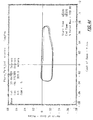
- Position data from GPS velocity information propagated positions is smoother than GPS position data which is not accurate enough by itself for turn-by-turn vehicle position propagation.
- FIGS. 4a and 4c show a position plot of the raw GPS position information for a vehicle
- FIGS. 4b and 4d show a propagation of the vehicle position over the same path using GPS velocity information.
- the GPS velocity information provides a much smoother plot of vehicle position.
- each sensor needs to have calibrations performed on it.
- the calibrations will be performed using known good data from the GPS receiver 18.
- the GPS receiver 18 has velocity accuracy to within one meter per second.
- the GPS velocity information becomes less accurate in low velocity states of less than 1.5 m/s.
- the GPS velocity information is time tagged so that it matches a particular set of odometer and accelerometer data on a per second basis. Map matching provides correction factors, but they are based on long term trends and not directly associated with any specify time interval.
- Sensor calibration using the GPS velocities will involve the following sensors in this particular embodiment.
- Odometer Vehicle Speed Sensor Calibration.
- the odometer output is the number of ticks of a counter, with a specified number of ticks to be equal to one unit of linear distance traversed.
- An example is that the GM Vehicle Speed Sensor has 4000 pulses per mile. This will have a default value from the factory and a calibrated value stored in FLASH thereafter.
- the odometer will be calibrated once per second from the GPS velocity and acceleration that occurred over that same time period, when valid GPS data is available.
- the lateral accelerometer measures centripetal acceleration. It is used to compute turn angle from the equation: Turn angle in radians is equal to the quotient of centripetal acceleration and tangential velocity.
- the lateral accelerometer has two values which need to be calibrated: The zero offset and the scale factor.
- the zero offset is the measurement that the accelerometer outputs when a no acceleration state exists.
- the scale factor is the number that is multiplied by the difference between the accelerometer read value and the accelerometer zero offset to compute the number of G's of acceleration. The first derivative of the GPS velocities will be used to compute the scale factor calibration.
- the longitudinal accelerometer measures the acceleration along the nose/tail axis of the vehicle, with a positive acceleration being out the nose (forward) and a negative acceleration being out the rear of the vehicle.
- the longitudinal accelerometer has two values which need to be calibrated: The zero offset and the scale factor.
- the zero offset is the measurement that the accelerometer outputs when an no acceleration state exists.
- the scale factor is the number that is multiplied by the difference between the accelerometer read value and the accelerometer zero offset to compute the number of G's of acceleration. The first derivative of the GPS velocities will be used to compute the scale factor calibration.
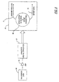
- FIG. 5 shows the zero motion detect system with a motion sensor 64 (an orthogonal axes accelerometer in this embodiment) providing motion signals.
- An amplifier 65 amplifies the motion signals, and in this particular embodiment, the motion signals are digitized in an analog to digital converter 67.
- the motion signals are provided to a sensor filter block 69 which is in the application unit 22.
- the vehicle navigation system determines a zero motion state by comparing samples of the motion signals from the motion sensor 64, such as an accelerometer, a gyro, or piezoelectric sensors with a threshold (the threshold is determined by vehicle vibration characteristics for the type of vehicle that the unit is mounted in, or the threshold for motion sensor could be set using other sensors which suggest zero motion, such as odometer, GPS or DGPS).
- the vehicle navigation system uses at least one of the samples to determine the zero offsets if the zero motion state is detected. At least two samples are preferred to compare over a time interval and averaging those samples to obtain a zero offset for the motion sensor 64. If a zero motion state exists, the vehicle navigation system sets a zero motion flag 71 and uses at least one of the samples to determine the zero offset for the sensor providing the processed motion signals.
- the system also provides offset data signals 73 which reflect the zero offset for the sensor providing the motion signals or the raw data used to calculate the zero offset.
- the vehicle navigation system can resolve ambiguity of low velocity GPS measurements because the velocity is zero. GPS velocities do not go to zero, so ambiguities exist when in a low velocity state of less than 1.5 m/s. If a zero motion flag is on, then the ambiguities in the GPS velocity information are resolved because the system is not moving. As such, the system freezes the heading and can also set the speed component of velocity to zero.
- the use of a zero motion detect system in a vehicle navigation system is described in more detail in copending U.S. patent application no. 08/579 ,903 , entitled "Zero Motion Detection System For Improved Vehicle Navigation System" and filed concurrently with this application.
- FIGS. 6a and 6b show a general flowchart illustrating how the improved vehicle navigation system 10 using the multiple orthogonal axes accelerometer 28 and the odometer 29 propagates a previous position to a current position.
- the improved vehicle navigation system determines if the vehicle is in a zero motion state as described above. If so, the system, at step 152, sets the change in distance to zero, locks the heading and current position, and calibrates the zero offsets.
- the system determines that the vehicle is moving, the system proceeds to step 154 to determine if a GPS solution is available. If GPS is available, the system uses the GPS velocity information to determine the current position.
- the GPS velocity information is very accurate above velocities of 1.5 m/s because GPS delta ranges are used to calculate the velocities.
- Using the GPS velocities for position propagation has other advantages. For example, the GPS receiver does not require calibration because of no inherent drift, and the GPS measurements can be used to calibrate other sensors. Moreover, cheaper sensors can be used because there is no need to use the sensors very often, and the sensors can be calibrated very often using the GPS measurements.
- the GPS receiver supports portability because it is independent of the vehicle and does not require a link to the vehicle odometer and reverse gear.
- e ⁇ dist ( e ⁇ vel ⁇ ⁇ t ) + 1 / 2 ( e ⁇ acc ⁇ ⁇ t ) 2
- n ⁇ dist ( n ⁇ vel ⁇ ⁇ t ) + 1 / 2 ( n ⁇ acc ⁇ ⁇ t ) 2
- the system calibrates the sensor items, such as the accelerometer scale factors and the odometer distance using information from the equations described above. The system can keep the sensors well calibrated because calibrating can occur once per second (scale factors) if the vehicle speed is above 1.5 m/s.
- the system checks at step 58 whether any GPS measurements are available. If so, the system computes the velocity information from the available subset of delta range measurements at step 160. If, at step 162, the velocity information is good, the system calculates current position using the equations 1-6 at step 164 but without calibrating the acceleration scale factors and the odometer distance in this embodiment. If the GPS velocity is determined not to be good at step 162, the system checks the heading component of the GPS velocity at step 166.
- the change in distance is set with the odometer distance, and the heading is set with the GPS heading calculated from the GPS delta range measurements Alternatively, an odometer is not used, and the distance is derived from the longitudinal acceleration information.
- the system determines at step 166 that the GPS heading is not valid (GPS blockage or low velocity) or at step 158 that the GPS measurements are insufficient, the system falls back on the orthogonal axes accelerometer(s) and the odometer in this particular embodiment.
- GPS velocity information is subject to errors at speeds of less than 1.5m/s, unless using a more accurate GPS system. For example, in a vehicle navigation system using DGPS, the threshold velocity is lower because of the higher accuracy of the system. As such, the vehicle navigation system proceeds to step 172 to determine the change in distance using lateral and longitudinal acceleration information from the orthogonal axes accelerometer(s).
- the system compares the longitudinal distance from the accelerometer with the odometer distance, and if the difference between them exceeds a threshold value, the odometer distance is used at step 176. If the difference is less than the threshold, then the accelerometer distance or the odometer distance can be used for the distance at step 178.
- the system uses equations 7 and 8 to determine the east and north distances and equations 5 and 6 to determine position.
- the system could fall back on only the orthogonal axes accelerometer(s). As shown in dashed step 173, if an odometer is not used, the distance is derived from the longitudinal acceleration information.
- the use of multiple, orthogonal axes acceleration information to propagate a vehicle position from a previous position to a current position is described in more detail in copending U.S. patent application no. 08/580,150 , entitled “Improved Vehicle Navigation System And Method Using Multiple Axes Accelerometer” and filed on concurrently with this application.
- step 182 the current position is compared with the GPS position. If the current position is within an acceptable distance from the GPS position, the system determines that the current position is valid at step 184. If not, the system replaces the current position with the GPS position at step 186. At this point, the system sends to a map matching step 188 a position and velocity, which has speed and heading components. Depending on the configuration of the map database 30, other information can be sent to the map matching block 188, such as heading and distance based on the current and previous positions, a current position and figures of merit (FOM) for each.
- FOM current position and figures of merit
- the map matching block 188 sends back a map matched current position, distance, heading, FOMs for each and calibration data.
- the map matching block 188 interrogates the map database 30 (FIG. 2a) to obtain a heading of the mapped path segment which the vehicle is determined to be traversing.
- the map matching block 188 updates the heading associated with the current position to obtain an updated current position.
- the map matching block 188 uses the map heading to update the heading based on the GPS velocity information.
- the vehicle navigation system 10 uses GPS velocity information to propagate a previous position 191 to a current position 192 (by adding displacements 194 and 196 obtained from the velocity information (integrated) to the previous position). If the difference between the GPS heading and the map heading is within a threshold, then the map heading is used as the heading for position propagation.
- the vehicle navigation system 10 can accomplish this in alternative ways. For example, as shown in FIG. 7b using GPS velocities, the vehicle navigation system 10 rotates the GPS velocity vector 200 to align with the map heading 202 if the GPS and map headings are within the threshold and integrates the rotated GPS velocity vector 204 to obtain the displacements. As shown, the updated current position 206 is obtained by applying orthogonal displacements 208 and 210 to the previous position 191.
- Errors usually involve heading determinations due to drift errors in gyro or compass. Displacement is easy to test and one of the most accurate components in the GPS measurements and also in the sensors, so the system uses the entire displacements from the GPS velocity information or the dead reckoning sensors, such as the accelerometers. Thus, the improved vehicle navigation system can use low cost sensors which are less sensitive because heading can be corrected with map heading.
- the improved vehicle navigation system relies on the GPS information for positioning and a high frequency of sensor calibration because GPS information is available a great deal of the time.
- the improved vehicle navigation system can use the map matching block 188 to provide an overall check on the current position and to provide position and heading correction data which is used if map matching 188 determines it is highly reliable.
- the current position (w/o map matching) is determined once per second. If the vehicle has travelled more than 15 meters since the last call to map matching 188, then the current position is passed to map matching 188. If the vehicle is travelling at high speed, the system will go to map matching 88 at each current position determination at the maximum rate of once per second.
- GPS is not available or unreliable, the improved vehicle navigation system has well calibrated sensors to rely on, and the improved vehicle navigation system can rely more on the information from the map matching block 188 for positioning and sensor calibration.
- the improved vehicle navigation system provides several significant advantages, such as flexibility, modularity, and accuracy at a cheaper cost because GPS information can be used to calibrate sensors more often and updating can be performed at a complete stop. These advantages occur because the system relies heavily on GPS velocity information to propagate vehicle position.
- the GPS velocity information is more reliable (within about 1 m/s) than the GPS position data (within about 100 m).
- Position data from GPS velocity information propagated positions is smoother than GPS position data which is not accurate enough by itself for turn-by-turn vehicle position propagation.
Abstract
Description
- The present invention relates generally to an improved vehicle navigation system, using an electromagnetic wave positioning system. More particularly, the present invention relates to an improved vehicle navigation system and method using GPS data.
- Current vehicle navigation systems use GPS, such as an electromagnetic wave positioning system, to determine a vehicle's position: Such a GPS system is the Navigation Satellite Timing and Ranging (NAVSTAR) Global Positioning System, which is a space-based satellite radio navigation system developed by the U.S. Department of Defense (DoD). GPS includes NAVSTAR GPS and its successors, Differential GPS (DGPS), or any other electromagnetic wave positioning systems. NAVSTAR GPS receivers provide users with continuous three-dimensional position, velocity, and time data.
- NAVSTAR GPS consists of three major segments: Space, Control, and User as illustrated in Figure 1. The
space segment 2 consists of a nominal constellation of 24 operational satellites which have been placed in 6 orbital planes above the Earth's surface. The satellites are in circular orbits in an orientation which normally provides a GPS user with a minimum of five satellites in view from any point on Earth at any one time. The satellites broadcast an RF signal which is modulated by a precise ranging signal and a coarse acquisition code ranging signal to provide navigation data. - This navigation data, which is computed and controlled by the
GPS control segment 4, includes the satellite's time, its clock correction and ephemeris parameters, almanacs, and health status for all GPS satellites. From this information, the user computes the satellite's precise position and clock offset. - The control segment consists of a Master Control Station and a number of monitor stations at various locations around the world. Each monitor station tracks all the GPS satellites in view and passes the signal measurement data back to the master control station. There, computations are performed to determine precise satellite ephemeris and satellite clock errors. The master control station generates the upload of user navigation data from each satellite. This data is subsequently rebroadcast by the satellite as part of its navigation data message.
- The
user segment 6 is the collection of all GPS receivers and their application support equipment such as antennas and processors. This equipment allows users to receive, decode, and process the information necessary to obtain accurate position, velocity and timing measurements. This data is used by the receiver's support equipment for specific application requirements. GPS supports a wide variety of applications including navigation, surveying, and time transfer. - GPS receivers may be used in a standalone mode or integrated with other systems. Currently, land-based navigation systems use vehicle speed sensor, rate gyro and a reverse gear hookup to "dead reckon" the vehicle position from a previously known position. This method of dead reckoning, however, is susceptible to sensor error, and therefore requires more expensive sensors for accuracy and dependability.
- GPS has been used as a position back-up in use for land-based applications, in which position propagation is computed by "dead reckoning" using speed and heading. In determining the propagation of postion, however, these systems are susceptible to the errors inherent in the reported GPS position and the errors in the dead reckoning calculation using speed and heading.
- Additionally, prior systems use a road network stored in a map database to calculate current vehicle positions. These systems send distance and heading information to perform map matching, and map matching calculates the current position based on the road network and the inputted data. These systems also use map matching to calibrate sensors. Map matching, however, has inherent inaccuracies because map matching must look back in time and match data to a location. As such, map matching can only calibrate the sensors when an absolute position is identified on the map, but on a long, straight stretch of highway, sensor calibration using map matching may not occur for a significant period of time.
- EP-A-0 527 558 discloses a navigation system having a GPS receiver and a stand-alone unit with a speed sensor that generates pulses upon sensing rotation of an axle. The navigation system calculates a distance between two subsequent position calculations by a GPS receiver. That calculated distance is then used to calibrate the stand-alone speed sensor. A similar system is disclosed in US-A-4 903 212.
- Accordingly, there is a need for a vehicle navigation system which is more accurate, efficient, flexible and cost-effective and potentially portable in propagating a previous vehicle position to a current vehicle position.
- In accordance with the present invention, an improved vehicle navigation system as defined in
claim 1 and a method as defined inclaim 6 are provided. - The improved vehicle navigation system and method uses information from a Global Positioning System (GPS) to obtain velocity vectors, which include speed and heading components, for propagating or "dead reckoning" the vehicle position from a previous position to a current position. The improved vehicle navigation system has a GPS receiver which provides the GPS velocity information which is calculated from a full set of GPS delta range measurements. GPS position data alone is not accurate enough for certain applications, such as turn-by-turn route guidance in automobile applications, because its error may be 100m and there is considerable position drift, even when stationary. GPS velocities are much more accurate than the position data, 1m/s or thereabouts, and can be used to propagate a known position forward and be more accurate over time than the GPS position solution. These velocities are instantaneous and not those computed from differencing two positions. The current position is calculated by adding displacements obtained from the GPS velocities to the previous position.
- This calculation process will improve position data once a known point can be used as a reference to start the propagation. An application where map matching will produce a reference point with high degree of accuracy, most likely after a significant maneuver such as a change in direction, will provide a good starting point for position propagation based on GPS velocities. This will help to eliminate velocity drift in long duration tests and scenarios. Thus, these velocities can be used to propagate vehicle position forward with as much, if not greater, accuracy than the current solution of vehicle speed and rate gyro. Because the GPS information should almost always be available, the improved vehicle navigation system relies less on its sensors, thereby allowing for the use of inexpensive sensors. The improved vehicle navigation system retains the accuracy of the sensors by repeatedly calibrating them with the GPS data obtained from the GPS velocity information. The improved vehicle navigation system calibrates the sensors whenever GPS data is available (for example, once a second at relatively high speeds). Furthermore, the improved vehicle navigation system does not need to rely on map matching to calibrate sensors. System flexibility is improved because map matching is oblivious to the hardware, and the system hardware can be updated without affecting map matching or a change in the map database. When GPS velocity information is not available, a dead reckoning approach using sensors is necessary.
- In the present invention, the improved position determination system eliminates the use of the Vehicle Speed Signal by using a longitudinally mounted accelerometer. This allows the improved position determination system to be portable.
- Other aspects and advantages of the present invention may become apparent upon reading the following detailed description and upon reference to the drawings in which:
- FIG 1 is a general illustration of the various segments in the NAVSTAR GPS system.
- FIG. 2 shows variations of an improved vehicle navigation system according to the principles of the present invention;
- FIG. 3 shows a block/data flow diagram of a version of the improved vehicle navigation system of FIG. 2;
- FIGS. 4a and 4c show graphic plots of vehicle position using raw GPS position data, and FIGS. 4b and 4d show graphic plots of vehicle position using GPS velocity information;
- FIG. 5 shows a block diagram of a zero motion detect system according to the principles of the present invention;
- FIGS. 6a and 6b show a general flow chart of the operation of an embodiment of the improved vehicle navigation system of FIG. 3; and
- FIGS. 7a-7c show general diagrams illustrating how the improved vehicle navigation system updates the GPS heading information with the map heading for position propagations.
- While the invention is Susceptible to various modifications and alterative forms, specifics thereof have been shown by way of example in the drawings and will be described in detail. It should be understood, however, that the intention is not to limit the invention to the particular embodiment described
- An illustrative embodiment of the improved position determination system according to the principles of the present invention and methodology is described below as it might be implemented using GPS velocities to determine a current position from a previous position. In the interest of clarity, not all features of an actual implementation are described in this specification. It will of course be appreciated that in the development of any such actual implementation (as in any development project), numerous implementation-specific decisions must be made to achieve the developers' specific goals and subgoals, such as compliance with system- and business-related constraints, which will vary from one implementation to another. Moreover, it will be appreciated that such a development effort might be complex and time-consuming, but would nevertheless be a routine undertaking of device engineering for those of ordinary skill having the benefit of this disclosure.
- Aspects of the improved vehicle navigation system has application in connection with a variety of system configurations in which GPS signals can be used for position determination. Such a vehicle navigation system is disclosed in copending patent application serial no. 08/580 ,150 , entitled "Improved Vehicle Navigation System And Method" and filed concurrently with this application. Other configurations are possible as would be understood by one of ordinary skill in the art.
- FIG. 2 illustrates, in block diagram form, exemplary arrangements of an improved
vehicle navigation system 10 for anautomobile 12. In this embodiment, the improvedvehicle navigation system 10 uses aGPS antenna 14 to receive the GPS signals. Theantenna 14 is preferably of right-hand circular polarization, has a gain minimum of -3dBiC above 5 degree elevation, and has a gain maximum of +6 dBiC. Patch or Helix antennas matching these specifications can be used. TheGPS antenna 14 can be connected to apreamplifier 16 to amplify the GPS signals received by theantenna 14. Thepre-amplifier 16 is optional, and the GPS antenna can be directly connected to aGPS receiver 18. - The
GPS receiver 18 continuously determines geographic position by measuring the ranges (the distance between a satellite with known coordinates in space and the receiver's antenna) of several satellites and computing the geometric intersection of these ranges. To determine a range, thereceiver 18 measures the time required for the GPS signal to travel from the satellite to the receiver antenna. The timing code generated by each satellite is compared to an identical code generated by thereceiver 18. The receiver's code is shifted until it matches the satellite's code. The resulting time shift is multiplied by the speed of light to arrive at the apparent range measurement. - Since the resulting range measurement contains propagation delays due to atmospheric effects, and satellite and receiver clock errors, it is referred to as a "pseudorange." Changes in each of these pseudoranges over a short period of time are also measured and processed by the
receiver 18. These measurements, referred to as delta range measurements or "delta-pseudoranges," are used to compute velocity. Delta ranges are in meters per second which are calculated by the receiver from pseudoranges, and theGPS receiver 18 can track the carrier phase of the GPS signals to smooth out the psuedoranges. The velocity and time data is generally computed once a second. If one of the position components is known, such as altitude, only three satellite pseudorange measurements are needed for thereceiver 18 to determine its velocity and time. In this case, only three satellites need to be tracked. - The error in the range measurement is dependent on one of two levels of GPS accuracy to which the user has access. PPS is the most accurate, but is reserved for use by the DoD and certain authorized users. SPS is less accurate and intended for general public use. The SPS signal is intentionally degraded to a certain extent by a process known as Selective Availability (SA). SA is used to limit access to the full accuracy of SPS in the interest of U.S. national security. Differential GPS (DGPS) may be used to correct certain bias-like errors in the GPS signals. A Reference Station receiver measures ranges from all visible satellites to its surveyed position. Differences between the measured and estimated ranges are computed and transmitted via radio or other signals to differential equipped receivers/hosts in a local area. Incorporation of these corrections into the ranee measurements can improve their position accuracy.
- As shown in FIG. 2, the
GPS receiver 18 provides GPS measurements to anapplication unit 22. Theapplication unit 22 consists ofapplication processing circuitry 24, such as a processor, memory, busses, the application software and related circuitry, andinterface hardware 26. In one embodiment of the present invention, theapplication unit 22 can be incorporated into theGPS receiver 18. Theinterface hardware 26 integrates the various components of thevehicle navigation system 10 with theapplication unit 22. - The
system 10 can include a combination of the features, such as those shown in dashed lines. For example, the improved vehicle navigation system could rely upon information provided by theGPS receiver 18, an accelerometer 28 (which in certain embodiments is an orthogonal axes accelerometer of recently available low cost, micromachined accelerometers) and themap database 30 to propagate vehicle position. In additional embodiments, the improvedvehicle navigation system 10 uses theaccelerometer 28, anodometer 29 and amap database 30 according to other aspects of the present invention. Other embodiments can include aspeed sensor 34, a headingsensor 36, such as a gyro, compass or differential odometer, and a one or twoway communication link 38. Other configurations and combinations are possible which incorporate aspects of the present invention as would be understood by one of ordinary skill in the art. Moreover, the improved vehicle navigation system can be incorporated in an advanced driver information system which controls and provides information on a variety of automobile functions. - FIG. 3 shows a block and data flow diagram for the improved
vehicle navigation system 10 which reveals the flexibility and accuracy of certain embodiments of the improved vehicle navigation system. TheGPS receiver 18 provides position information, velocity information, psuedoranges and delta pseudoranges to thesensor integrator 40. Thesensor integrator 40 uses the velocity information to determine a current position for the vehicle. In this embodiment, if GPS velocity information is not available, thesensor integrator 40 can calculate GPS velocity using the available delta range measurements to determine a current position. GPS velocity information is derived from a set of delta range measurements, and if only a subset of delta range measurements is available, the vehicle navigation system can derive GPS velocity information from the subset of delta range measurements. The vehicle navigation system uses the GPS position information at start-up as a current position and during other times of operation as a check against the current position. If the current position fails the check, then the GPS position can replace the current position. - If GPS velocity information is not available, certain embodiments can obtain the information used to propagate the vehicle position from the sensors. The
sensor 28, which is a multiple axis accelerometer, provides acceleration information for at least two orthogonal axes (lateral, longitudinal and/or vertical) to the application unit. Theodometer 29 provides information which can be used in place of the information derived from the accelerometers. Other available information can include the odometer distance and GPS heading, a distance calculation and map heading, the GPS speed information and map heading, gyro heading and longitudinal speed and other variations. - A
map database 30 stores map information, such as a road network, and provides map information to theapplication unit 22. The map database should have some level of known accuracy, confidence, or defined error. In this embodiment, every change in street segment heading is designated as a shape point which has a heading with a fixed measurement error. Auser interface 32, which includes a display and keyboard, allows interaction between the user and the improvedvehicle navigation system 10. In this embodiment, if the difference between the current heading and the map heading is less than a threshold value, then the map heading is used as the heading.Application processor 22 calibrates


- In any event, if GPS is available or not, the
sensor integrator 40 provides the current position and a velocity (speed and heading) to amap matching block 42. Themap matching block 42 provides road segment information for the road segment that the vehicle is determined to be traveling on, such as heading, and a suggested position. Thesensor integrator 40 can update the heading component of the velocity information with the heading provided by themap matching block 42 to update the current position. If themap matching block 42 indicates a good match, then the map matched position can replace the current position. If not, the sensor integrator propagates the previous position to the current position using the velocity information. As such, thesensor integrator 40 determines the current position and provides the current position to a user interface and/orroute guidance block 46. - The
map matching block 42 also provides correction data, such as a distance scale factor and/or offset and a turn rate scale factor and/or offset, to asensor calibration block 44. Thesensor integrator 40 also provides correction data to thesensor calibration block 44. The correction data from thesensor integrator 40, however, is based on the GPS information. Thus, accurate correction data based on the GPS information is continuously available to calibrate the sensors 28 (2 or 3 axis accelerometer) as well as forother sensors sensor calibration block 44 until a good match is found between the map information and the current position. If a highly accurate match is found by map matching 42, most likely after a significant maneuver such as a change in direction, the map matched position is used as a reference point or starting position for position propagation according to the principles of the present invention. - The
sensor calibration block 44 contains the sensor calibration parameters, such as scale factors and zero factors for thesensors sensor integrator 40 to calibrate the sensors 28-36. In one embodiment, the system can combine thesensor integrator 40 andsensor calibration 44 intoGPS engine 18 using its processor. In certain embodiments, the route guidance and user interface, thesensor integrator 40 and thesensor calibration 44 is performed on an application specific integrated circuit (ASIC). - If the accuracy of a current position is determined to be high (for example, a map matched position at a isolated turn), the improved
vehicle navigation system 10 can update the current position with the known position. After the vehicle has moved a distance from the known position which is now a previous position, the improved vehicle navigation system must accurately propagate the vehicle position from the previous position to the current position. - The calculations that will be performed to compute the vehicle position will take place in three coordinate frames. The vehicle position will be reported in geodetic coordinates (latitude, longitude, altitude). The non-GPS data will be provided in body or platform coordinates. The GPS velocities and the equations used for velocity propagation of position will take place in the North, East, Down frame.
- The geodetic frame is a representation of the Earth Centered Earth Fixed (ECEF) coordinates that is based on spherical trigonometry. This is the coordinate frame that the mapping database uses. Its units are degrees and meters displacement in height above the geoid. These coordinates will be with respect to the WGS-84 Earth model, which is the Earth model used by the Global Positioning System (GPS). This is mathematically equivalent to the North American Datum 1983 (NAD 83) system which the mapping database is referenced to. The North East Down frame is a right-handed orthonormal coordinate system fixed to the vehicle with its axes pointing to the True North, True East, and True Down (perpendicular to the Earth) directions. The body coordinates form a right-handed orthonormal coordinate system with their origin at the navigation unit, the x axis pointing toward the nose of the vehicle, the right axis pointing out the right door of the vehicle and the z axis pointing down perpendicular to the Earth.
- During normal operation of a particular embodiment of the system (with an odometer and orthogonal axes accelerometer), and with GPS information available, the following are the equations that will be used for computing the vehicle position and the calibration of the accelerometers and odometer.
-


- The following superscripts will be used to denote the origin of the data:
- G =
- GPS
- A =
- Accelerometer
- O =
- Odometer
- The following subscripts will denote time - either time of validity or time period of integration:
- t =
- current time
- t-1 =
- time of last data set before the current data set
- t-2 =
- time of data set before t-1
- Note that t-1 and t-2 do not necessarily imply a one second difference, but only data collection and/or data validity times.
- The following subscripts will denote coordinate reference frames:
- N =
- North East Down
- B =
- Body (Nose Right Door Down)
- G =
- Geodetic (latitude longitude height)
- To use the information from the non-GPS sensors, their data needs to be rotated from the body frame to the North East Down frame. This is a rotation about the yaw axis measured in degrees from True North to the Nose Axis of the vehicle. The equations for this is:

- The steady state position propagation equation is based on the physical definition of velocity and acceleration. The current position is equal to the previous position plus the integral of velocity plus the double integral of acceleration.

- The following information is collected at time t:

ẋ e = Velocity in the True East direction (meters/second);
ẋ n = Velocity in the True North direction (meters/second);
ẋ u = Velocity in the Up direction (meters/second);

x̅ The raw GPS position;


- The following other information is available for use at time t, but was collected at a previous time:


- When GPS is available and has produced a valid position and velocity solution, the following equation will be used for the propagation of the vehicle position:


- This equation is: the current position is equal to the previous position plus the GPS velocity (vector) times the delta time plus the GPS acceleration from two time periods ago minus the Accelerometer acceleration from two time periods ago (a correction factor) plus the Accelerometer acceleration from the current second. In certain embodiments, other sensor information, such as the odometer information, can be used in the above equations if it is determined to be more appropriate than the accelerometer information.
- Also computed at this second are:
- (1) the GPS heading 1 computed as the inverse tangent of the East and North velocities:

- (2) the distance from time t-1 to time t, computed from the GPS velocity valid at time t-1 and the double integration of the longitudinal Accelerometer acceleration from time t-1 to time t:

- (3) the distance from time t-2 to time t-1, computed from the GPS velocity and acceleration from time t-2 to time t-1. This will be used as a calibration factor for both the Vehicle Speed Sensor and the Longitudinal accelerometer:

- (4) the change in heading from time t-2 to time t-1 from the GPS heading computed at those times. This is used as a correction factor for the lateral accelerometer.

- Position data from GPS velocity information propagated positions is smoother than GPS position data which is not accurate enough by itself for turn-by-turn vehicle position propagation. For example, FIGS. 4a and 4c show a position plot of the raw GPS position information for a vehicle, and FIGS. 4b and 4d show a propagation of the vehicle position over the same path using GPS velocity information. As shown, the GPS velocity information provides a much smoother plot of vehicle position.
- To maintain the system accuracy when GPS velocity information is not available, each sensor needs to have calibrations performed on it. The calibrations will be performed using known good data from the
GPS receiver 18. TheGPS receiver 18 has velocity accuracy to within one meter per second. The GPS velocity information becomes less accurate in low velocity states of less than 1.5 m/s. The GPS velocity information is time tagged so that it matches a particular set of odometer and accelerometer data on a per second basis. Map matching provides correction factors, but they are based on long term trends and not directly associated with any specify time interval. Sensor calibration using the GPS velocities will involve the following sensors in this particular embodiment. - Odometer (Vehicle Speed Sensor) Calibration. The odometer output is the number of ticks of a counter, with a specified number of ticks to be equal to one unit of linear distance traversed. An example is that the GM Vehicle Speed Sensor has 4000 pulses per mile. This will have a default value from the factory and a calibrated value stored in FLASH thereafter. The odometer will be calibrated once per second from the GPS velocity and acceleration that occurred over that same time period, when valid GPS data is available.
- Lateral Accelerometer. The lateral accelerometer measures centripetal acceleration. It is used to compute turn angle from the equation: Turn angle in radians is equal to the quotient of centripetal acceleration and tangential velocity. The lateral accelerometer has two values which need to be calibrated: The zero offset and the scale factor. The zero offset is the measurement that the accelerometer outputs when a no acceleration state exists. The scale factor is the number that is multiplied by the difference between the accelerometer read value and the accelerometer zero offset to compute the number of G's of acceleration. The first derivative of the GPS velocities will be used to compute the scale factor calibration.
- Longitudinal Accelerometer. The longitudinal accelerometer measures the acceleration along the nose/tail axis of the vehicle, with a positive acceleration being out the nose (forward) and a negative acceleration being out the rear of the vehicle. The longitudinal accelerometer has two values which need to be calibrated: The zero offset and the scale factor. The zero offset is the measurement that the accelerometer outputs when an no acceleration state exists. The scale factor is the number that is multiplied by the difference between the accelerometer read value and the accelerometer zero offset to compute the number of G's of acceleration. The first derivative of the GPS velocities will be used to compute the scale factor calibration.
- The zero motion detect system shown in FIG 5 is used to resolve ambiguity in the GPS velocity information. FIG. 5 shows the zero motion detect system with a motion sensor 64 (an orthogonal axes accelerometer in this embodiment) providing motion signals. An
amplifier 65 amplifies the motion signals, and in this particular embodiment, the motion signals are digitized in an analog todigital converter 67. The motion signals are provided to asensor filter block 69 which is in theapplication unit 22. The vehicle navigation system determines a zero motion state by comparing samples of the motion signals from themotion sensor 64, such as an accelerometer, a gyro, or piezoelectric sensors with a threshold (the threshold is determined by vehicle vibration characteristics for the type of vehicle that the unit is mounted in, or the threshold for motion sensor could be set using other sensors which suggest zero motion, such as odometer, GPS or DGPS). The vehicle navigation system uses at least one of the samples to determine the zero offsets if the zero motion state is detected. At least two samples are preferred to compare over a time interval and averaging those samples to obtain a zero offset for themotion sensor 64. If a zero motion state exists, the vehicle navigation system sets a zeromotion flag 71 and uses at least one of the samples to determine the zero offset for the sensor providing the processed motion signals. - The system also provides offset data signals 73 which reflect the zero offset for the sensor providing the motion signals or the raw data used to calculate the zero offset. Upon detecting a zero motion state, the vehicle navigation system can resolve ambiguity of low velocity GPS measurements because the velocity is zero. GPS velocities do not go to zero, so ambiguities exist when in a low velocity state of less than 1.5 m/s. If a zero motion flag is on, then the ambiguities in the GPS velocity information are resolved because the system is not moving. As such, the system freezes the heading and can also set the speed component of velocity to zero. The use of a zero motion detect system in a vehicle navigation system is described in more detail in copending U.S. patent application no. 08/579 ,903 , entitled "Zero Motion Detection System For Improved Vehicle Navigation System" and filed concurrently with this application.
- FIGS. 6a and 6b show a general flowchart illustrating how the improved
vehicle navigation system 10 using the multipleorthogonal axes accelerometer 28 and theodometer 29 propagates a previous position to a current position. Atstep 150, the improved vehicle navigation system determines if the vehicle is in a zero motion state as described above. If so, the system, atstep 152, sets the change in distance to zero, locks the heading and current position, and calibrates the zero offsets. - If the system determines that the vehicle is moving, the system proceeds to step 154 to determine if a GPS solution is available. If GPS is available, the system uses the GPS velocity information to determine the current position. The GPS velocity information is very accurate above velocities of 1.5 m/s because GPS delta ranges are used to calculate the velocities. Using the GPS velocities for position propagation has other advantages. For example, the GPS receiver does not require calibration because of no inherent drift, and the GPS measurements can be used to calibrate other sensors. Moreover, cheaper sensors can be used because there is no need to use the sensors very often, and the sensors can be calibrated very often using the GPS measurements. The GPS receiver supports portability because it is independent of the vehicle and does not require a link to the vehicle odometer and reverse gear.
- As shown in
step 156, the system calculates east and north accelerations as follows:

- The accelerations are used to calculate east and north displacements as follows:


- The current position is calculated as follows:


where degrees/meter represents a conversion factor of meter to degrees, taking into consideration the shrinking number of meters in a degree of longitude as the distance from the Equator increases. Finally, atstep 156, the system calibrates the sensor items, such as the accelerometer scale factors and the odometer distance using information from the equations described above. The system can keep the sensors well calibrated because calibrating can occur once per second (scale factors) if the vehicle speed is above 1.5 m/s. - If a full GPS solution is not available at
step 154, the system checks at step 58 whether any GPS measurements are available. If so, the system computes the velocity information from the available subset of delta range measurements atstep 160. If, atstep 162, the velocity information is good, the system calculates current position using the equations 1-6 atstep 164 but without calibrating the acceleration scale factors and the odometer distance in this embodiment. If the GPS velocity is determined not to be good atstep 162, the system checks the heading component of the GPS velocity atstep 166. If the GPS heading component is determined to be valid, then atstep 168, the change in distance is set with the odometer distance, and the heading is set with the GPS heading calculated from the GPS delta range measurements Alternatively, an odometer is not used, and the distance is derived from the longitudinal acceleration information. With this heading and distance, the system calculates a position (lat, long) atstep 170 using the equations as follows:

position using equations - If the system determines at
step 166 that the GPS heading is not valid (GPS blockage or low velocity) or atstep 158 that the GPS measurements are insufficient, the system falls back on the orthogonal axes accelerometer(s) and the odometer in this particular embodiment. GPS velocity information is subject to errors at speeds of less than 1.5m/s, unless using a more accurate GPS system. For example, in a vehicle navigation system using DGPS, the threshold velocity is lower because of the higher accuracy of the system. As such, the vehicle navigation system proceeds to step 172 to determine the change in distance using lateral and longitudinal acceleration information from the orthogonal axes accelerometer(s). Atstep 174, the system compares the longitudinal distance from the accelerometer with the odometer distance, and if the difference between them exceeds a threshold value, the odometer distance is used atstep 176. If the difference is less than the threshold, then the accelerometer distance or the odometer distance can be used for the distance atstep 178. Once the change in distance is determined, the system calculates the position atstep 180 using the following equations to determine heading as follows:


equations 7 and 8 to determine the east and north distances andequations - According to some aspects of the present invention, the system could fall back on only the orthogonal axes accelerometer(s). As shown in dashed
step 173, if an odometer is not used, the distance is derived from the longitudinal acceleration information. The use of multiple, orthogonal axes acceleration information to propagate a vehicle position from a previous position to a current position is described in more detail in copending U.S. patent application no. 08/580,150 , entitled "Improved Vehicle Navigation System And Method Using Multiple Axes Accelerometer" and filed on concurrently with this application. - After determining the initial current position at
step step 184. If not, the system replaces the current position with the GPS position atstep 186. At this point, the system sends to a map matching step 188 a position and velocity, which has speed and heading components. Depending on the configuration of themap database 30, other information can be sent to themap matching block 188, such as heading and distance based on the current and previous positions, a current position and figures of merit (FOM) for each. - The
map matching block 188 sends back a map matched current position, distance, heading, FOMs for each and calibration data. In this embodiment, themap matching block 188 interrogates the map database 30 (FIG. 2a) to obtain a heading of the mapped path segment which the vehicle is determined to be traversing. Themap matching block 188 updates the heading associated with the current position to obtain an updated current position. As such, themap matching block 188 uses the map heading to update the heading based on the GPS velocity information. - As shown in FIG. 7a, the
vehicle navigation system 10 uses GPS velocity information to propagate aprevious position 191 to a current position 192 (by addingdisplacements vehicle navigation system 10 can accomplish this in alternative ways. For example, as shown in FIG. 7b using GPS velocities, thevehicle navigation system 10 rotates theGPS velocity vector 200 to align with the map heading 202 if the GPS and map headings are within the threshold and integrates the rotatedGPS velocity vector 204 to obtain the displacements. As shown, the updatedcurrent position 206 is obtained by applyingorthogonal displacements previous position 191. - Errors usually involve heading determinations due to drift errors in gyro or compass. Displacement is easy to test and one of the most accurate components in the GPS measurements and also in the sensors, so the system uses the entire displacements from the GPS velocity information or the dead reckoning sensors, such as the accelerometers. Thus, the improved vehicle navigation system can use low cost sensors which are less sensitive because heading can be corrected with map heading.
- FIG. 7c shows an alternative way of updating the GPS heading and thus the current position by projecting the
velocity vector 200 to align with the map heading 202 and integrating the projectedvelocity 212 to obtaindisplacements system 10 obtains the updatedcurrent position 192 by applying thedisplacements previous position 191. Depending on the information available and the particular embodiment, the improved vehicle navigation system can react differently to the information provided by themap matching block 188. - The improved vehicle navigation system relies on the GPS information for positioning and a high frequency of sensor calibration because GPS information is available a great deal of the time. When GPS is available, the improved vehicle navigation system can use the
map matching block 188 to provide an overall check on the current position and to provide position and heading correction data which is used if map matching 188 determines it is highly reliable. In this particular embodiment, the current position (w/o map matching) is determined once per second. If the vehicle has travelled more than 15 meters since the last call to map matching 188, then the current position is passed to map matching 188. If the vehicle is travelling at high speed, the system will go to map matching 88 at each current position determination at the maximum rate of once per second. When GPS is not available or unreliable, the improved vehicle navigation system has well calibrated sensors to rely on, and the improved vehicle navigation system can rely more on the information from themap matching block 188 for positioning and sensor calibration. - Thus, the improved vehicle navigation system provides several significant advantages, such as flexibility, modularity, and accuracy at a cheaper cost because GPS information can be used to calibrate sensors more often and updating can be performed at a complete stop. These advantages occur because the system relies heavily on GPS velocity information to propagate vehicle position. The GPS velocity information is more reliable (within about 1 m/s) than the GPS position data (within about 100 m). Position data from GPS velocity information propagated positions is smoother than GPS position data which is not accurate enough by itself for turn-by-turn vehicle position propagation.
- The principles of the present invention, which have been disclosed by way of the above examples and discussion, can be implemented using various navigation system configurations and sensors. The improved vehicle navigation system, for instance, can be implemented without using an odometer connection and obtaining distance information from the accelerometer inputs when GPS is not available to improve portability and installation costs. Those skilled in the art will readily recognize that these and various other modifications and changes may be made to the present invention without strictly following the exemplary application illustrated and described herein and without departing from the scope of the present invention, which is set forth in the following claims.
Claims (10)
- A navigation system (10) having a GPS receiver (18) which provides GPS velocity information derived from delta range measurements and an accelerometer which provides acceleration information, characterized in that said navigation system (10) is adapted to calculate a displacement based upon 1) said GPS velocity information over a time interval 2) said acceleration information over the time interval, and 3) GPS acceleration information over the time interval based on the GPS velocity information, said vehicle navigation system (10) adding said displacement to a previous position (191) to obtain a current position (192).
- The system of claim 1 wherein said system determines east and north displacements from said GPS velocity information and applies said east and north displacements to said previous position to obtain said current position.
- The system of claim 1 further including sensors (29,34,36) providing information used to propagate vehicle position if said GPS velocity information is not available, said vehicle navigation system (10) determines calibration information from said GPS velocity information to calibrate said sensors (29,34,36).
- The system of claim 1 wherein said accelerometer (28) is an orthogonal axes accelerometer providing longitudinal and lateral acceleration information, said vehicle navigation system (10) determines longitudinal and lateral calibration information from said GPS velocity information to calibrate said orthogonal axes accelerometer.
- The system of claim 1 further including a zero motion detection system (22) which provides a zero motion signal upon detecting a zero motion state to resolve ambiguity of low velocity GPS information.
- A method of determining a current vehicle position (192) from a previous position (191) including the steps of:a) providing GPS velocity information derived from delta range measurements and providing accelerometer acceleration information:
characterized by the further steps of:b) calculating a displacement based upon 1) said GPS velocity information over a time interval 2) said acceleration information over the time interval, and 3) GPS acceleration information over the time interval based on the GPS velocity information;c) adding said displacement to said previous position (191) to obtain said current vehicle position (192). - The method of claim 6 wherein said step b) includes the step of determining east and north displacements from said GPS velocity information, and said step c) includes the step of applying said east and north displacements to said previous position to obtain said current position.
- The method of claim 6 further including the step of providing a zero motion signal upon detecting a zero motion state to resolve ambiguity of low velocity GPS information.
- The method of claim 6 further including the steps of:providing sensor information used to propagate vehicle position if said GPS velocity information is not available; anddetermining calibration information from said GPS velocity information to calibrate said sensors.
- The method of claim 6 further including the steps of:providing longitudinal and lateral acceleration information by an orthogonal axes accelerometer;determining longitudinal and lateral calibration information from said GPS velocity information to calibrate said orthogonal axes accelerometer.
Applications Claiming Priority (3)
| Application Number | Priority Date | Filing Date | Title |
|---|---|---|---|
| US579902 | 1990-09-07 | ||
| US08/579,902 US6029111A (en) | 1995-12-28 | 1995-12-28 | Vehicle navigation system and method using GPS velocities |
| PCT/US1996/020852 WO1997024583A1 (en) | 1995-12-28 | 1996-12-27 | Improved vehicle navigation system and method using gps velocities |
Publications (2)
| Publication Number | Publication Date |
|---|---|
| EP0870174A1 EP0870174A1 (en) | 1998-10-14 |
| EP0870174B1 true EP0870174B1 (en) | 2006-08-23 |
Family
ID=24318813
Family Applications (1)
| Application Number | Title | Priority Date | Filing Date |
|---|---|---|---|
| EP96945964A Expired - Lifetime EP0870174B1 (en) | 1995-12-28 | 1996-12-27 | Improved vehicle navigation system and method using gps velocities |
Country Status (6)
| Country | Link |
|---|---|
| US (1) | US6029111A (en) |
| EP (1) | EP0870174B1 (en) |
| JP (1) | JP2000502802A (en) |
| AT (1) | ATE337541T1 (en) |
| DE (1) | DE69636482T2 (en) |
| WO (1) | WO1997024583A1 (en) |
Cited By (1)
| Publication number | Priority date | Publication date | Assignee | Title |
|---|---|---|---|---|
| TWI392848B (en) * | 2008-05-23 | 2013-04-11 | Ind Tech Res Inst | Method for identifying the orientation and navigation apparatus using the same |
Families Citing this family (122)
| Publication number | Priority date | Publication date | Assignee | Title |
|---|---|---|---|---|
| US6308134B1 (en) * | 1996-12-27 | 2001-10-23 | Magellan Dis, Inc. | Vehicle navigation system and method using multiple axes accelerometer |
| DE19757333C1 (en) * | 1997-12-22 | 1999-09-16 | Litef Gmbh | Automatic, fast calibration of an on-board measurement of a speed vector |
| US6181329B1 (en) * | 1997-12-23 | 2001-01-30 | Ricoh Company, Ltd. | Method and apparatus for tracking a hand-held writing instrument with multiple sensors that are calibrated by placing the writing instrument in predetermined positions with respect to the writing surface |
| US9075136B1 (en) | 1998-03-04 | 2015-07-07 | Gtj Ventures, Llc | Vehicle operator and/or occupant information apparatus and method |
| DE19861486B4 (en) * | 1998-03-18 | 2013-07-25 | Robert Bosch Gmbh | Data apparatus for a motor vehicle for a vehicle navigation system |
| GB9900358D0 (en) * | 1999-01-09 | 1999-02-24 | Hussey Christopher S | Journey logging |
| FR2791849B1 (en) * | 1999-03-31 | 2001-06-29 | Cit Alcatel | NODE AND ON-BOARD STATION FOR ESTABLISHING A COMMUNICATION TO A PASSENGER OF A VEHICLE AT ANY TIME |
| US6381536B1 (en) | 1999-06-21 | 2002-04-30 | Nissan Motor Co., Ltd. | Apparatus for generating road information from stored digital map database |
| EP1218694B1 (en) * | 1999-09-16 | 2006-11-15 | Sirf Technology, Inc. | Navigation system and method for tracking the position of an object |
| US6484089B1 (en) * | 1999-10-15 | 2002-11-19 | Magellan Dis, Inc. | Navigation system with road condition sampling |
| US20020022924A1 (en) * | 2000-03-07 | 2002-02-21 | Begin John David | Propagation of position with multiaxis accelerometer |
| JP2001280974A (en) * | 2000-03-28 | 2001-10-10 | Clarion Co Ltd | Gps receiver with function of sampling dr sensor |
| CA2413691C (en) * | 2000-06-23 | 2010-09-14 | Sportvision, Inc. | Track model constraint for gps position |
| FI108372B (en) | 2000-06-30 | 2002-01-15 | Nokia Corp | Method and apparatus for position measurement |
| US6411897B1 (en) | 2000-07-10 | 2002-06-25 | Iap Intermodal, Llc | Method to schedule a vehicle in real-time to transport freight and passengers |
| US6240362B1 (en) | 2000-07-10 | 2001-05-29 | Iap Intermodal, Llc | Method to schedule a vehicle in real-time to transport freight and passengers |
| US20020115436A1 (en) * | 2000-09-29 | 2002-08-22 | Howell Robert M. | Telematics system |
| US6401036B1 (en) * | 2000-10-03 | 2002-06-04 | Motorola, Inc. | Heading and position error-correction method and apparatus for vehicle navigation systems |
| US6577952B2 (en) | 2001-01-08 | 2003-06-10 | Motorola, Inc. | Position and heading error-correction method and apparatus for vehicle navigation systems |
| US6567741B1 (en) * | 2001-11-01 | 2003-05-20 | General Motors Corporation | Method and system for reducing shape points for a navigation system |
| US6629031B2 (en) * | 2001-11-06 | 2003-09-30 | Volvo Trucks North America, Inc. | Vehicle tampering protection system |
| US6581546B1 (en) | 2002-02-14 | 2003-06-24 | Waters Instruments, Inc. | Animal containment system having a dynamically changing perimeter |
| JP2003307524A (en) * | 2002-04-15 | 2003-10-31 | Pioneer Electronic Corp | Acceleration data correction device, its correction method, its correction program, recording medium for recording its correction program and navigation device |
| FR2842315B1 (en) * | 2002-07-09 | 2004-09-03 | I2A | METHOD FOR AUTOMATICALLY GUIDING AND CONTROLLING AN APPARATUS AND A DEVICE IMPLEMENTING THE METHOD |
| US6907347B2 (en) * | 2002-11-21 | 2005-06-14 | Ford Global Technologies, Llc | Systems and method for estimating speed and pitch sensor errors |
| GB0227749D0 (en) * | 2002-11-28 | 2003-01-08 | Koninkl Philips Electronics Nv | Position determination for a mobile device |
| JP4086237B2 (en) * | 2003-07-07 | 2008-05-14 | 本田技研工業株式会社 | Vehicle navigation system |
| KR100518852B1 (en) * | 2003-08-25 | 2005-09-30 | 엘지전자 주식회사 | Method for dead reckoning for backward improvement of mobile |
| JP2005195395A (en) * | 2004-01-05 | 2005-07-21 | Mitsubishi Electric Corp | Moving object acceleration/distance estimating circuit, pseudo-distance estimating circuit for positioning navigation, moving object positioning device, and moving object positioning method |
| IL159838A0 (en) * | 2004-01-13 | 2004-06-20 | Yehuda Binder | Information device |
| US7251493B2 (en) | 2004-02-13 | 2007-07-31 | Sony Ericsson Mobile Communications Ab | Mobile terminals and methods for determining a location based on acceleration information |
| US7535402B1 (en) * | 2004-04-19 | 2009-05-19 | Novariant, Inc. | Navigation with satellite communications |
| US8022329B2 (en) * | 2004-12-07 | 2011-09-20 | Lockheed Martin Corporation | System and method for full escort mixed mail sorter using mail clamps |
| JP2006176084A (en) * | 2004-12-24 | 2006-07-06 | Advics:Kk | Detection value correction method for vehicle behavior sensor |
| US7908080B2 (en) | 2004-12-31 | 2011-03-15 | Google Inc. | Transportation routing |
| US9601015B2 (en) | 2005-02-25 | 2017-03-21 | Concaten, Inc. | Maintenance decision support system and method for vehicular and roadside applications |
| US7355509B2 (en) | 2005-02-25 | 2008-04-08 | Iwapi Inc. | Smart modem device for vehicular and roadside applications |
| US7330122B2 (en) * | 2005-08-10 | 2008-02-12 | Remotemdx, Inc. | Remote tracking and communication device |
| JP4816302B2 (en) * | 2005-09-06 | 2011-11-16 | ソニー株式会社 | Acceleration sensor offset detection apparatus, acceleration sensor offset detection method, acceleration sensor offset detection program, and navigation apparatus |
| US20070155360A1 (en) * | 2005-12-30 | 2007-07-05 | Yafan An | Methods, Apparatuses and Systems for the Reporting of Roadway Speed and Incident Data and the Constructing of Speed Map Database |
| JP2007232635A (en) * | 2006-03-02 | 2007-09-13 | Seiko Epson Corp | Positioning device, control method of positioning device, control program of positioning device and computer readable medium recording control program of positioning device |
| JP3875714B2 (en) * | 2006-03-09 | 2007-01-31 | 三菱電機株式会社 | Moving body acceleration / distance estimation circuit, moving body positioning device, and moving body positioning method |
| TR200603512A2 (en) * | 2006-07-07 | 2008-02-21 | Sungur Nai̇m | Smartograph electronic tachograph system. |
| US8797210B2 (en) * | 2006-07-14 | 2014-08-05 | Securealert, Inc. | Remote tracking device and a system and method for two-way voice communication between the device and a monitoring center |
| US7737841B2 (en) * | 2006-07-14 | 2010-06-15 | Remotemdx | Alarm and alarm management system for remote tracking devices |
| US7936262B2 (en) * | 2006-07-14 | 2011-05-03 | Securealert, Inc. | Remote tracking system with a dedicated monitoring center |
| JP4816340B2 (en) * | 2006-08-31 | 2011-11-16 | ソニー株式会社 | Navigation device, position detection method, and position detection program |
| JP4816339B2 (en) * | 2006-08-31 | 2011-11-16 | ソニー株式会社 | Navigation device, navigation information calculation method, and navigation information calculation program |
| TWI287621B (en) * | 2006-09-15 | 2007-10-01 | Sin Etke Technology Co Ltd | Precision positioning system for vehicles |
| US8095309B2 (en) * | 2007-06-05 | 2012-01-10 | GM Global Technology Operations LLC | GPS assisted vehicular longitudinal velocity determination |
| US8275522B1 (en) | 2007-06-29 | 2012-09-25 | Concaten, Inc. | Information delivery and maintenance system for dynamically generated and updated data pertaining to road maintenance vehicles and other related information |
| US9864957B2 (en) | 2007-06-29 | 2018-01-09 | Concaten, Inc. | Information delivery and maintenance system for dynamically generated and updated data pertaining to road maintenance vehicles and other related information |
| US20090254274A1 (en) * | 2007-07-27 | 2009-10-08 | Kulik Victor | Navigation system for providing celestial and terrestrial information |
| JP4466705B2 (en) * | 2007-09-21 | 2010-05-26 | ヤマハ株式会社 | Navigation device |
| US8554475B2 (en) | 2007-10-01 | 2013-10-08 | Mitac International Corporation | Static and dynamic contours |
| US8467804B2 (en) * | 2007-10-16 | 2013-06-18 | Sony Corporation | Mobile terminals and methods for regulating power-on/off of a GPS positioning circuit |
| WO2009088946A1 (en) | 2008-01-03 | 2009-07-16 | Iwapi, Inc. | Integrated rail efficiency and safety support system |
| US8232876B2 (en) * | 2008-03-07 | 2012-07-31 | Securealert, Inc. | System and method for monitoring individuals using a beacon and intelligent remote tracking device |
| US8072379B2 (en) * | 2008-05-12 | 2011-12-06 | Qualcomm Incorporated | GPS power savings using low power sensors |
| US8024013B2 (en) * | 2008-07-09 | 2011-09-20 | Sony Ericsson Mobile Communications Ab | Regulating power duty cycle of an RF transmitter/receiver responsive to distance moved |
| US9816821B2 (en) * | 2008-09-04 | 2017-11-14 | Apple Inc. | Location systems for handheld electronic devices |
| US8103404B2 (en) * | 2008-11-13 | 2012-01-24 | Ezurio Limited | System and method for odometer calibration |
| US20100152933A1 (en) * | 2008-12-11 | 2010-06-17 | Honeywell International Inc. | Apparatus and method for unmanned aerial vehicle ground proximity detection, landing and descent |
| US8359178B2 (en) * | 2009-03-04 | 2013-01-22 | Honeywell International Inc. | Method and apparatus for identifying erroneous sensor outputs |
| JP5556101B2 (en) * | 2009-09-17 | 2014-07-23 | ソニー株式会社 | Direction calculation apparatus, correction value initialization method, and mobile phone with direction calculation function |
| US9403415B2 (en) * | 2009-10-12 | 2016-08-02 | Ford Global Technologies | GPS based pitch sensing for an integrated stability control system |
| DE102009053817C5 (en) * | 2009-11-18 | 2016-07-07 | Knorr-Bremse Systeme für Nutzfahrzeuge GmbH | Vehicle with braking torque from rear wheels to the front wheels transmitting brake device with brake slip control |
| US8514070B2 (en) | 2010-04-07 | 2013-08-20 | Securealert, Inc. | Tracking device incorporating enhanced security mounting strap |
| US8902081B2 (en) | 2010-06-02 | 2014-12-02 | Concaten, Inc. | Distributed maintenance decision and support system and method |
| US8843340B2 (en) | 2010-06-23 | 2014-09-23 | Aisin Aw Co., Ltd. | Track information generating device, track information generating method, and computer-readable storage medium |
| US20120218142A1 (en) * | 2010-08-26 | 2012-08-30 | Maxlinear, Inc. | Reporting of Last Acquired Position During Gap of Satellite Reception for GNSS Systems |
| US8548739B2 (en) | 2011-02-10 | 2013-10-01 | Telenav, Inc. | Navigation system with interactive accelerometer mechanism and method of operation thereof |
| US10169822B2 (en) | 2011-12-02 | 2019-01-01 | Spireon, Inc. | Insurance rate optimization through driver behavior monitoring |
| US8510200B2 (en) | 2011-12-02 | 2013-08-13 | Spireon, Inc. | Geospatial data based assessment of driver behavior |
| US9482296B2 (en) | 2012-06-05 | 2016-11-01 | Apple Inc. | Rendering road signs during navigation |
| US10156455B2 (en) | 2012-06-05 | 2018-12-18 | Apple Inc. | Context-aware voice guidance |
| US9182243B2 (en) | 2012-06-05 | 2015-11-10 | Apple Inc. | Navigation application |
| US8965696B2 (en) | 2012-06-05 | 2015-02-24 | Apple Inc. | Providing navigation instructions while operating navigation application in background |
| US9997069B2 (en) | 2012-06-05 | 2018-06-12 | Apple Inc. | Context-aware voice guidance |
| US10176633B2 (en) | 2012-06-05 | 2019-01-08 | Apple Inc. | Integrated mapping and navigation application |
| US9047691B2 (en) | 2012-06-05 | 2015-06-02 | Apple Inc. | Route display and review |
| US9146125B2 (en) | 2012-06-05 | 2015-09-29 | Apple Inc. | Navigation application with adaptive display of graphical directional indicators |
| US8880336B2 (en) | 2012-06-05 | 2014-11-04 | Apple Inc. | 3D navigation |
| US9319831B2 (en) | 2012-06-05 | 2016-04-19 | Apple Inc. | Mapping application with automatic stepping capabilities |
| US8983778B2 (en) | 2012-06-05 | 2015-03-17 | Apple Inc. | Generation of intersection information by a mapping service |
| US9886794B2 (en) | 2012-06-05 | 2018-02-06 | Apple Inc. | Problem reporting in maps |
| US9418672B2 (en) | 2012-06-05 | 2016-08-16 | Apple Inc. | Navigation application with adaptive instruction text |
| US9430941B2 (en) | 2012-06-10 | 2016-08-30 | Apple Inc. | Harvesting traffic information from mobile devices |
| US9194702B2 (en) * | 2012-06-29 | 2015-11-24 | Symbol Technologies, Llc | Methods and apparatus for adjusting heading direction in a navigation system |
| US9002641B2 (en) | 2012-10-05 | 2015-04-07 | Hand Held Products, Inc. | Navigation system configured to integrate motion sensing device inputs |
| US9405011B2 (en) | 2012-10-05 | 2016-08-02 | Hand Held Products, Inc. | Navigation system configured to integrate motion sensing device inputs |
| US9406222B2 (en) | 2012-10-18 | 2016-08-02 | Calamp Corp. | Systems and methods for location reporting of detected events in vehicle operation |
| US9779379B2 (en) | 2012-11-05 | 2017-10-03 | Spireon, Inc. | Container verification through an electrical receptacle and plug associated with a container and a transport vehicle of an intermodal freight transport system |
| US8933802B2 (en) | 2012-11-05 | 2015-01-13 | Spireon, Inc. | Switch and actuator coupling in a chassis of a container associated with an intermodal freight transport system |
| US10107831B2 (en) | 2012-11-21 | 2018-10-23 | Calamp Corp | Systems and methods for efficient characterization of acceleration events |
| JP6008124B2 (en) * | 2013-02-18 | 2016-10-19 | 株式会社デンソー | Vehicle orientation detection method and vehicle orientation detection device |
| US9459277B2 (en) | 2013-02-19 | 2016-10-04 | Calamp Corp. | Systems and methods for 3-axis accelerometer calibration with vertical sample buffers |
| US10466269B2 (en) * | 2013-02-19 | 2019-11-05 | Calamp Corp. | Systems and methods for low latency 3-axis accelerometer calibration |
| US20140288824A1 (en) * | 2013-03-22 | 2014-09-25 | Qualcomm Incorporated | Method and/or system for selective application of direction of travel |
| US9541420B2 (en) * | 2013-04-03 | 2017-01-10 | Caterpillar Inc. | System for determining error in a sensed machine position |
| US9779449B2 (en) | 2013-08-30 | 2017-10-03 | Spireon, Inc. | Veracity determination through comparison of a geospatial location of a vehicle with a provided data |
| JP6324408B2 (en) * | 2013-11-29 | 2018-05-16 | クラリオン株式会社 | Distance coefficient learning apparatus, distance coefficient learning method, and current position calculation apparatus |
| US20150186991A1 (en) | 2013-12-31 | 2015-07-02 | David M. Meyer | Creditor alert when a vehicle enters an impound lot |
| US9644972B2 (en) * | 2015-03-06 | 2017-05-09 | Tallysman Wireless Inc. | Method for tracking a path taken by a vehicle |
| US9802487B2 (en) | 2015-03-13 | 2017-10-31 | Classic Automotive Innovations, Llc | Speedometer drive system and method |
| US10036636B2 (en) * | 2015-03-19 | 2018-07-31 | Vricon Systems Aktiebolag | Position determining unit and a method for determining a position of a land or sea based object |
| US9551788B2 (en) | 2015-03-24 | 2017-01-24 | Jim Epler | Fleet pan to provide measurement and location of a stored transport item while maximizing space in an interior cavity of a trailer |
| US9644977B2 (en) | 2015-05-22 | 2017-05-09 | Calamp Corp. | Systems and methods for determining vehicle operational status |
| US10214166B2 (en) | 2015-06-11 | 2019-02-26 | Calamp Corp. | Systems and methods for impact detection with noise attenuation of a sensor signal |
| DE102015218810A1 (en) * | 2015-09-29 | 2017-03-30 | Continental Teves Ag & Co. Ohg | Method for selecting location algorithms in a vehicle |
| CN108139212B (en) * | 2015-10-15 | 2021-07-09 | 三菱电机株式会社 | Positioning device and positioning method |
| US10262546B2 (en) * | 2016-04-13 | 2019-04-16 | Ge Aviation Systems Llc | Aircraft navigation using exponential map |
| US10055909B2 (en) | 2016-07-08 | 2018-08-21 | Calamp Corp. | Systems and methods for crash determination |
| US10395438B2 (en) | 2016-08-19 | 2019-08-27 | Calamp Corp. | Systems and methods for crash determination with noise filtering |
| US10219117B2 (en) | 2016-10-12 | 2019-02-26 | Calamp Corp. | Systems and methods for radio access interfaces |
| US10473750B2 (en) | 2016-12-08 | 2019-11-12 | Calamp Corp. | Systems and methods for tracking multiple collocated assets |
| US10599421B2 (en) | 2017-07-14 | 2020-03-24 | Calamp Corp. | Systems and methods for failsafe firmware upgrades |
| US20190141156A1 (en) | 2017-11-06 | 2019-05-09 | Calamp Corp. | Systems and Methods for Dynamic Telematics Messaging |
| US11206171B2 (en) | 2017-11-07 | 2021-12-21 | Calamp Corp. | Systems and methods for dynamic device programming |
| CN110927755B (en) * | 2019-11-14 | 2021-10-15 | 深圳市麦谷科技有限公司 | Filtering method and device for vehicle drift point |
| CN111208546B (en) * | 2019-12-26 | 2022-08-02 | 深圳市元征科技股份有限公司 | Vehicle positioning data acquisition method and device, vehicle-mounted equipment and storage medium |
| CN112634489B (en) * | 2020-12-09 | 2022-12-09 | 众安在线财产保险股份有限公司 | Vehicle state determination method, device and system based on mobile terminal |
Family Cites Families (91)
| Publication number | Priority date | Publication date | Assignee | Title |
|---|---|---|---|---|
| US3749893A (en) * | 1971-12-22 | 1973-07-31 | D Hileman | Vehicle navigation system |
| US3789198A (en) * | 1972-04-10 | 1974-01-29 | Boeing Co | Vehicle location monitoring system |
| US3845289A (en) * | 1972-07-18 | 1974-10-29 | Avon Inc | Method and apparatus employing automatic route control system |
| GB1470694A (en) * | 1974-06-08 | 1977-04-21 | Marconi Co Ltd | Vehicle location systems |
| US4032758A (en) * | 1975-11-05 | 1977-06-28 | The Boeing Company | Compensated vehicle heading system |
| US4107689A (en) * | 1976-06-07 | 1978-08-15 | Rca Corporation | System for automatic vehicle location |
| US4086632A (en) * | 1976-09-27 | 1978-04-25 | The Boeing Company | Area navigation system including a map display unit for establishing and modifying navigation routes |
| DE2805628A1 (en) * | 1978-02-10 | 1979-08-16 | Teldix Gmbh | METHOD OF DETERMINING THE DRIFT OF A GYRO |
| US4254465A (en) * | 1978-08-03 | 1981-03-03 | Dynamic Sciences International, Inc. | Strap-down attitude and heading reference system |
| US4253150A (en) * | 1978-09-29 | 1981-02-24 | Scovill Royal J | Pictorial navigation computer |
| GB2115946B (en) | 1978-12-21 | 1984-02-01 | Redifon Simulation Ltd | Improvements in or relating to visual display apparatus |
| US4312577A (en) * | 1979-08-13 | 1982-01-26 | Fitzgerald J Vincent | Motor vehicle map display system |
| DE2941331A1 (en) * | 1979-10-11 | 1981-04-23 | Siemens AG, 1000 Berlin und 8000 München | AUTHENTIC NAVIGATION DEVICE FOR ROAD VEHICLES |
| US4301506A (en) * | 1980-07-07 | 1981-11-17 | Turco Daniel J | Auto routing computer for eliminating the need for maps or travel instructions |
| US4351027A (en) * | 1980-08-13 | 1982-09-21 | Honeywell Inc. | Adaptive riser angle position reference system |
| US4369441A (en) * | 1980-09-18 | 1983-01-18 | Louis Wohlmuth | Display control system |
| JPS57144589A (en) * | 1981-03-04 | 1982-09-07 | Nissan Motor | Picture display unit |
| JPS6049914B2 (en) * | 1981-03-27 | 1985-11-05 | 日産自動車株式会社 | Vehicle travel guidance device |
| JPS57169785A (en) * | 1981-04-13 | 1982-10-19 | Nissan Motor | Travelling guidance system for car |
| JPS57186111A (en) * | 1981-05-13 | 1982-11-16 | Nissan Motor Co Ltd | Map display device for vehicle |
| JPS57201808A (en) * | 1981-06-08 | 1982-12-10 | Nippon Denso Co Ltd | Navigator to be mounted on car |
| US4513377A (en) * | 1981-06-11 | 1985-04-23 | Nippondenso Co., Ltd. | Vehicle-mounted navigator |
| JPS57206818A (en) * | 1981-06-15 | 1982-12-18 | Toyota Motor Corp | Display device for running trace |
| DE3273841D1 (en) * | 1981-07-07 | 1986-11-20 | Nippon Denso Co | Mobile navigator |
| JPS589017A (en) * | 1981-07-10 | 1983-01-19 | Niles Parts Co Ltd | Guiding and displaying device for travelling of automobile |
| JPS5827008A (en) * | 1981-08-12 | 1983-02-17 | Nissan Motor Co Ltd | Device for guiding running of vehicle |
| JPH0619276B2 (en) * | 1981-08-17 | 1994-03-16 | 工業技術院長 | Portable map display device assembly |
| JPS58111969A (en) * | 1981-12-25 | 1983-07-04 | 日産自動車株式会社 | Running route display for vehicle |
| JPS58113711A (en) * | 1981-12-26 | 1983-07-06 | Japan Aviation Electronics Ind Ltd | Azimuth and locus display |
| US4660037A (en) * | 1982-01-28 | 1987-04-21 | Honda Giken Kogyo Kabushiki Kaisha | Current location indication apparatus for use in an automotive vehicle |
| MX152578A (en) * | 1982-03-10 | 1985-09-09 | Natividad Gene Esparza | IMPROVEMENTS TO THE COMPUTERIZED ELECTRONIC SYSTEM TO OBTAIN URBAN COORDINATES |
| JPS58178213A (en) * | 1982-04-14 | 1983-10-19 | Hitachi Ltd | Upright type position display device |
| US4404247A (en) * | 1982-07-02 | 1983-09-13 | Minnesota Mining And Manufacturing Company | Protective covering for magnetic recording medium |
| EP0103847B1 (en) * | 1982-09-16 | 1988-12-07 | TELDIX GmbH | Navigation aid for vehicles |
| DE3242904A1 (en) * | 1982-11-20 | 1984-05-24 | Teldix Gmbh, 6900 Heidelberg | DEVICE FOR DETERMINING THE LOCATION OF A VEHICLE |
| JPS59132099A (en) * | 1983-01-17 | 1984-07-30 | 株式会社デンソー | Running information system for vehicle |
| US4675676A (en) * | 1983-03-09 | 1987-06-23 | Nippondenso Co. Ltd. | Map display system |
| US4890104A (en) * | 1983-03-25 | 1989-12-26 | Nippondenso Co., Ltd. | Electronic map display system for use on vehicle |
| JPS59174713A (en) * | 1983-03-25 | 1984-10-03 | Nippon Denso Co Ltd | Vehicle mounted map display device |
| US4584646A (en) * | 1983-06-29 | 1986-04-22 | Harris Corporation | System for correlation and recognition of terrain elevation |
| JPS60135817A (en) * | 1983-12-26 | 1985-07-19 | Mazda Motor Corp | Running guide apparatus of car |
| US4639773A (en) * | 1984-04-17 | 1987-01-27 | Rca Corporation | Apparatus for detecting motion in a video image by comparison of a video line value with an interpolated value |
| US4796191A (en) * | 1984-06-07 | 1989-01-03 | Etak, Inc. | Vehicle navigational system and method |
| NL8402497A (en) * | 1984-08-14 | 1986-03-03 | Philips Nv | VEHICLE NAVIGATION SYSTEM EQUIPPED WITH AN ADAPTIVE INSURANCE NAVIGATION SYSTEM BASED ON MEASUREMENT OF THE SPEED AND CROSS-GEAR ACCELERATION OF THE VEHICLE AND PROVIDED WITH A CORRECTION UNIT FOR CORRECTING THE MEASURED VALUES. |
| GB8501012D0 (en) * | 1985-01-16 | 1985-02-20 | Gen Electric Co Plc | Automated vehicle drift correction |
| DE3519277A1 (en) * | 1985-05-30 | 1986-12-04 | Robert Bosch Gmbh, 7000 Stuttgart | NAVIGATION PROCEDURE FOR VEHICLES |
| US4711125A (en) * | 1985-11-06 | 1987-12-08 | Morrison Melvin M | Inertial measurement unit |
| JPH0621792B2 (en) * | 1986-06-26 | 1994-03-23 | 日産自動車株式会社 | Hybrid position measuring device |
| DE3768023D1 (en) * | 1986-09-25 | 1991-03-21 | Siemens Ag | NAVIGATION DEVICE FOR A VEHICLE. |
| KR910004416B1 (en) * | 1987-03-13 | 1991-06-27 | 미쓰비시덴기 가부시기가이샤 | Navigator |
| US4912645A (en) * | 1987-03-26 | 1990-03-27 | Mazda Motor Corporation | Automotive navigation system |
| DE3718996A1 (en) * | 1987-06-06 | 1988-12-22 | Bosch Gmbh Robert | METHOD AND DEVICE FOR DETERMINING THE POSITION OF A LANDING VEHICLE |
| JPH0820504B2 (en) * | 1987-09-22 | 1996-03-04 | 株式会社豊田中央研究所 | GPS navigation device |
| JPH01214711A (en) * | 1988-02-23 | 1989-08-29 | Toshiba Corp | Navigation apparatus |
| US5109344A (en) * | 1988-04-28 | 1992-04-28 | Mazda Motor Corporation | Vehicle navigation apparatus employing node selection, comparison and elimination techniques |
| DE3814958A1 (en) * | 1988-05-03 | 1989-11-16 | Teldix Gmbh | VEHICLE WITH A VEHICLE ORIENTATION SYSTEM |
| JPH07119617B2 (en) * | 1988-07-05 | 1995-12-20 | マツダ株式会社 | Vehicle navigation system |
| CA1321418C (en) * | 1988-10-05 | 1993-08-17 | Joseph C. Mcmillan | Primary land arctic navigation system |
| US5166882A (en) * | 1989-03-31 | 1992-11-24 | The United States Of America As Represented By The Secretary Of The Navy | System for calibrating a gyro navigator |
| DE3912108C2 (en) * | 1989-04-13 | 1997-04-30 | Teldix Gmbh | Orientation and positioning device for vehicles |
| US4954833A (en) * | 1989-07-05 | 1990-09-04 | The United States Of America As Represented By The Secretary Of The Navy | Method for determining astronomic azimuth |
| GB2241623A (en) * | 1990-02-28 | 1991-09-04 | Philips Electronic Associated | Vehicle location system |
| JP2979582B2 (en) * | 1990-05-23 | 1999-11-15 | ソニー株式会社 | Transmission system |
| US5058023A (en) * | 1990-07-30 | 1991-10-15 | Motorola, Inc. | Vehicle position determining apparatus |
| NL9001810A (en) * | 1990-08-13 | 1992-03-02 | Philips Nv | METHOD FOR DETERMINING THE POSITION OF A VEHICLE, DEVICE FOR DETERMINING THE POSITION OF A VEHICLE AND VEHICLE PROVIDED WITH THE DEVICE. |
| US5185610A (en) * | 1990-08-20 | 1993-02-09 | Texas Instruments Incorporated | GPS system and method for deriving pointing or attitude from a single GPS receiver |
| JPH04178587A (en) * | 1990-11-13 | 1992-06-25 | Matsushita Electric Ind Co Ltd | Car azimuth calculating device |
| CA2052709C (en) * | 1990-11-30 | 2002-12-17 | Ting Y. Chan | Apparatus for withdrawing stripper gas from an fccu reactor vessel |
| JPH04238220A (en) * | 1991-01-23 | 1992-08-26 | Sumitomo Electric Ind Ltd | Vehicle azimuth correcting device |
| EP0514887B1 (en) * | 1991-05-21 | 1997-04-16 | Matsushita Electric Industrial Co., Ltd. | Vehicle position detecting apparatus |
| EP0527558B1 (en) * | 1991-07-09 | 1995-11-15 | Pioneer Electronic Corporation | GPS navigation system with local speed direction sensing and PDOP accuracy evaluation |
| JP2961966B2 (en) * | 1991-07-15 | 1999-10-12 | 松下電器産業株式会社 | Vehicle position and orientation calculation device |
| US5233844A (en) * | 1991-08-15 | 1993-08-10 | Cryo-Cell International, Inc. | Storage apparatus, particularly with automatic insertion and retrieval |
| US5311195A (en) * | 1991-08-30 | 1994-05-10 | Etak, Inc. | Combined relative and absolute positioning method and apparatus |
| JPH0579846A (en) * | 1991-09-19 | 1993-03-30 | Matsushita Electric Ind Co Ltd | Vehicle position calculator |
| US5557524A (en) * | 1991-10-18 | 1996-09-17 | Maki; Stanley C. | GPS/GLONASS travel recorder |
| US5483457A (en) * | 1991-10-25 | 1996-01-09 | Matsushita Electric Industrial Co., Ltd. | Vehicle navigation system using GPS including correction of coefficients for velocity sensor |
| ES2106316T3 (en) * | 1991-11-22 | 1997-11-01 | Engineered Data Products Inc | DEVICE TO GENERATE LABELS. |
| JPH05157572A (en) * | 1991-12-10 | 1993-06-22 | Pioneer Electron Corp | Navigation system |
| JPH0731062B2 (en) * | 1992-02-10 | 1995-04-10 | 住友電気工業株式会社 | Gyro offset correction method and apparatus |
| DE69314219T2 (en) * | 1992-04-20 | 1998-03-12 | Sumitomo Electric Industries | Device for detecting the course of the vehicle |
| US5359529A (en) * | 1992-05-15 | 1994-10-25 | Zexel Corporation | Route guidance on/off-route state filter |
| US5361212A (en) * | 1992-11-02 | 1994-11-01 | Honeywell Inc. | Differential GPS landing assistance system |
| JPH06347278A (en) * | 1993-06-10 | 1994-12-20 | Alpine Electron Inc | Existent link detection method of vehicle |
| JP3302445B2 (en) * | 1993-06-18 | 2002-07-15 | パイオニア株式会社 | Navigation device |
| US5488559A (en) * | 1993-08-02 | 1996-01-30 | Motorola, Inc. | Map-matching with competing sensory positions |
| US5422814A (en) * | 1993-10-25 | 1995-06-06 | Trimble Navigation Limited | Global position system receiver with map coordinate system outputs |
| US5525998A (en) * | 1994-08-01 | 1996-06-11 | Motorola, Inc. | Odometer assisted GPS navigation method |
| US5594453A (en) * | 1994-11-01 | 1997-01-14 | Trimble Navigation, Ltd | GPS receiver having a rapid acquisition of GPS satellite signals |
| US5485161A (en) * | 1994-11-21 | 1996-01-16 | Trimble Navigation Limited | Vehicle speed control based on GPS/MAP matching of posted speeds |
| US5583776A (en) * | 1995-03-16 | 1996-12-10 | Point Research Corporation | Dead reckoning navigational system using accelerometer to measure foot impacts |
-
1995
- 1995-12-28 US US08/579,902 patent/US6029111A/en not_active Expired - Lifetime
-
1996
- 1996-12-27 DE DE69636482T patent/DE69636482T2/en not_active Expired - Lifetime
- 1996-12-27 AT AT96945964T patent/ATE337541T1/en not_active IP Right Cessation
- 1996-12-27 WO PCT/US1996/020852 patent/WO1997024583A1/en active Search and Examination
- 1996-12-27 EP EP96945964A patent/EP0870174B1/en not_active Expired - Lifetime
- 1996-12-27 JP JP09524602A patent/JP2000502802A/en active Pending
Cited By (1)
| Publication number | Priority date | Publication date | Assignee | Title |
|---|---|---|---|---|
| TWI392848B (en) * | 2008-05-23 | 2013-04-11 | Ind Tech Res Inst | Method for identifying the orientation and navigation apparatus using the same |
Also Published As
| Publication number | Publication date |
|---|---|
| WO1997024583A1 (en) | 1997-07-10 |
| DE69636482T2 (en) | 2007-08-23 |
| ATE337541T1 (en) | 2006-09-15 |
| JP2000502802A (en) | 2000-03-07 |
| EP0870174A1 (en) | 1998-10-14 |
| DE69636482D1 (en) | 2006-10-05 |
| US6029111A (en) | 2000-02-22 |
Similar Documents
| Publication | Publication Date | Title |
|---|---|---|
| EP0870174B1 (en) | Improved vehicle navigation system and method using gps velocities | |
| US5862511A (en) | Vehicle navigation system and method | |
| EP0870175B1 (en) | A zero motion detection system for improved vehicle navigation system | |
| US6308134B1 (en) | Vehicle navigation system and method using multiple axes accelerometer | |
| JP3062301B2 (en) | GPS navigation device | |
| US9488480B2 (en) | Method and apparatus for improved navigation of a moving platform | |
| EP0462648B1 (en) | Method of and apparatus for obtaining vehicle heading information | |
| US6091359A (en) | Portable dead reckoning system for extending GPS coverage | |
| EP0534892B1 (en) | Position-locating method | |
| US6381536B1 (en) | Apparatus for generating road information from stored digital map database | |
| EP0870172B1 (en) | Improved vehicle navigation system and method using a multiple axes accelerometer | |
| JP3877011B2 (en) | Position detection apparatus for automobiles having a satellite receiver | |
| EP1678518A2 (en) | Method and system for a data interface for aiding a satellite positioning system receiver | |
| JP2004069536A (en) | Data calibration device and method | |
| WO1998049577A2 (en) | Methods for gyro bias estimation using gps | |
| US5928295A (en) | Method and apparatus for automatic calibration of the wheel track of a movable vehicle | |
| US6720913B1 (en) | Lock slip detection using inertial information | |
| JP2786309B2 (en) | Vehicle position detection device | |
| KR100341801B1 (en) | Urban vehicle navigation system using multiple antennas | |
| JP2685624B2 (en) | Navigation system for moving objects | |
| JP2603766B2 (en) | Direction detection method and direction detection device | |
| JPH04198787A (en) | Bearing measuring method for navigation system | |
| Kaniewski et al. | Desing and simulative testing of DR/GPS system |
Legal Events
| Date | Code | Title | Description |
|---|---|---|---|
| PUAI | Public reference made under article 153(3) epc to a published international application that has entered the european phase |
Free format text: ORIGINAL CODE: 0009012 |
|
| 17P | Request for examination filed |
Effective date: 19980625 |
|
| AK | Designated contracting states |
Kind code of ref document: A1 Designated state(s): AT CH DE ES FR GB IT LI |
|
| 17Q | First examination report despatched |
Effective date: 20010424 |
|
| GRAP | Despatch of communication of intention to grant a patent |
Free format text: ORIGINAL CODE: EPIDOSNIGR1 |
|
| GRAS | Grant fee paid |
Free format text: ORIGINAL CODE: EPIDOSNIGR3 |
|
| GRAA | (expected) grant |
Free format text: ORIGINAL CODE: 0009210 |
|
| AK | Designated contracting states |
Kind code of ref document: B1 Designated state(s): AT CH DE ES FR GB IT LI |
|
| PG25 | Lapsed in a contracting state [announced via postgrant information from national office to epo] |
Ref country code: LI Free format text: LAPSE BECAUSE OF FAILURE TO SUBMIT A TRANSLATION OF THE DESCRIPTION OR TO PAY THE FEE WITHIN THE PRESCRIBED TIME-LIMIT Effective date: 20060823 Ref country code: IT Free format text: LAPSE BECAUSE OF FAILURE TO SUBMIT A TRANSLATION OF THE DESCRIPTION OR TO PAY THE FEE WITHIN THE PRE;WARNING: LAPSES OF ITALIAN PATENTS WITH EFFECTIVE DATE BEFORE 2007 MAY HAVE OCCURRED AT ANY TIME BEFORE 2007. THE CORRECT EFFECTIVE DATE MAY BE DIFFERENT FROM THE ONE RECORDED.SCRIBED TIME-LIMIT Effective date: 20060823 Ref country code: CH Free format text: LAPSE BECAUSE OF FAILURE TO SUBMIT A TRANSLATION OF THE DESCRIPTION OR TO PAY THE FEE WITHIN THE PRESCRIBED TIME-LIMIT Effective date: 20060823 Ref country code: AT Free format text: LAPSE BECAUSE OF FAILURE TO SUBMIT A TRANSLATION OF THE DESCRIPTION OR TO PAY THE FEE WITHIN THE PRESCRIBED TIME-LIMIT Effective date: 20060823 |
|
| REG | Reference to a national code |
Ref country code: GB Ref legal event code: FG4D |
|
| REG | Reference to a national code |
Ref country code: CH Ref legal event code: EP |
|
| REF | Corresponds to: |
Ref document number: 69636482 Country of ref document: DE Date of ref document: 20061005 Kind code of ref document: P |
|
| PG25 | Lapsed in a contracting state [announced via postgrant information from national office to epo] |
Ref country code: ES Free format text: LAPSE BECAUSE OF FAILURE TO SUBMIT A TRANSLATION OF THE DESCRIPTION OR TO PAY THE FEE WITHIN THE PRESCRIBED TIME-LIMIT Effective date: 20061204 |
|
| ET | Fr: translation filed | ||
| REG | Reference to a national code |
Ref country code: CH Ref legal event code: PL |
|
| PLBE | No opposition filed within time limit |
Free format text: ORIGINAL CODE: 0009261 |
|
| STAA | Information on the status of an ep patent application or granted ep patent |
Free format text: STATUS: NO OPPOSITION FILED WITHIN TIME LIMIT |
|
| 26N | No opposition filed |
Effective date: 20070524 |
|
| REG | Reference to a national code |
Ref country code: GB Ref legal event code: 732E |
|
| REG | Reference to a national code |
Ref country code: FR Ref legal event code: TP Ref country code: FR Ref legal event code: CJ Ref country code: FR Ref legal event code: CD |
|
| REG | Reference to a national code |
Ref country code: GB Ref legal event code: 732E Free format text: REGISTERED BETWEEN 20090507 AND 20090513 |
|
| REG | Reference to a national code |
Ref country code: FR Ref legal event code: TP |
|
| REG | Reference to a national code |
Ref country code: GB Ref legal event code: 732E Free format text: REGISTERED BETWEEN 20110915 AND 20110921 |
|
| REG | Reference to a national code |
Ref country code: FR Ref legal event code: TP Owner name: BEACON NAVIGATION INC., TW Effective date: 20110927 |
|
| REG | Reference to a national code |
Ref country code: DE Ref legal event code: R082 Ref document number: 69636482 Country of ref document: DE Representative=s name: PRINZ & PARTNER PATENTANWAELTE RECHTSANWAELTE, DE |
|
| REG | Reference to a national code |
Ref country code: DE Ref legal event code: R082 Ref document number: 69636482 Country of ref document: DE Representative=s name: PRINZ & PARTNER MBB PATENTANWAELTE RECHTSANWAE, DE Effective date: 20111206 Ref country code: DE Ref legal event code: R082 Ref document number: 69636482 Country of ref document: DE Representative=s name: PRINZ & PARTNER PATENTANWAELTE RECHTSANWAELTE, DE Effective date: 20111206 Ref country code: DE Ref legal event code: R081 Ref document number: 69636482 Country of ref document: DE Owner name: BEACON NAVIGATION GMBH, CH Free format text: FORMER OWNER: MITAC INTERNATIONAL CORP., KUEI-SHAN, TAO-YUAN, TW Effective date: 20111206 Ref country code: DE Ref legal event code: R081 Ref document number: 69636482 Country of ref document: DE Owner name: BEACON NAVIGATION GMBH, CH Free format text: FORMER OWNER: MITAC INTERNATIONAL CORP., KUEI-SHAN, TW Effective date: 20111206 |
|
| REG | Reference to a national code |
Ref country code: FR Ref legal event code: TP Owner name: BEACON NAVIGATION GMBH, CH Effective date: 20120118 |
|
| REG | Reference to a national code |
Ref country code: DE Ref legal event code: R082 Ref document number: 69636482 Country of ref document: DE Representative=s name: PRINZ & PARTNER PATENTANWAELTE RECHTSANWAELTE, DE |
|
| REG | Reference to a national code |
Ref country code: DE Ref legal event code: R082 Ref document number: 69636482 Country of ref document: DE Representative=s name: PRINZ & PARTNER PATENTANWAELTE RECHTSANWAELTE, DE Effective date: 20120522 Ref country code: DE Ref legal event code: R082 Ref document number: 69636482 Country of ref document: DE Representative=s name: PRINZ & PARTNER MBB PATENTANWAELTE RECHTSANWAE, DE Effective date: 20120522 Ref country code: DE Ref legal event code: R081 Ref document number: 69636482 Country of ref document: DE Owner name: BEACON NAVIGATION GMBH, CH Free format text: FORMER OWNER: BEACON NAVIGATION INC., APIA, WS Effective date: 20120522 |
|
| REG | Reference to a national code |
Ref country code: GB Ref legal event code: 732E Free format text: REGISTERED BETWEEN 20140403 AND 20140409 |
|
| REG | Reference to a national code |
Ref country code: FR Ref legal event code: PLFP Year of fee payment: 20 |
|
| PGFP | Annual fee paid to national office [announced via postgrant information from national office to epo] |
Ref country code: GB Payment date: 20151223 Year of fee payment: 20 |
|
| PGFP | Annual fee paid to national office [announced via postgrant information from national office to epo] |
Ref country code: FR Payment date: 20151110 Year of fee payment: 20 |
|
| PGFP | Annual fee paid to national office [announced via postgrant information from national office to epo] |
Ref country code: DE Payment date: 20151222 Year of fee payment: 20 |
|
| REG | Reference to a national code |
Ref country code: DE Ref legal event code: R071 Ref document number: 69636482 Country of ref document: DE |
|
| REG | Reference to a national code |
Ref country code: GB Ref legal event code: PE20 Expiry date: 20161226 |
|
| PG25 | Lapsed in a contracting state [announced via postgrant information from national office to epo] |
Ref country code: GB Free format text: LAPSE BECAUSE OF EXPIRATION OF PROTECTION Effective date: 20161226 |