EP0868669B1 - A tracking method for a radar system - Google Patents
A tracking method for a radar system Download PDFInfo
- Publication number
- EP0868669B1 EP0868669B1 EP96942984A EP96942984A EP0868669B1 EP 0868669 B1 EP0868669 B1 EP 0868669B1 EP 96942984 A EP96942984 A EP 96942984A EP 96942984 A EP96942984 A EP 96942984A EP 0868669 B1 EP0868669 B1 EP 0868669B1
- Authority
- EP
- European Patent Office
- Prior art keywords
- target
- gates
- target state
- tracking method
- tracking
- Prior art date
- Legal status (The legal status is an assumption and is not a legal conclusion. Google has not performed a legal analysis and makes no representation as to the accuracy of the status listed.)
- Expired - Lifetime
Links
Images


Classifications
-
- G—PHYSICS
- G01—MEASURING; TESTING
- G01S—RADIO DIRECTION-FINDING; RADIO NAVIGATION; DETERMINING DISTANCE OR VELOCITY BY USE OF RADIO WAVES; LOCATING OR PRESENCE-DETECTING BY USE OF THE REFLECTION OR RERADIATION OF RADIO WAVES; ANALOGOUS ARRANGEMENTS USING OTHER WAVES
- G01S13/00—Systems using the reflection or reradiation of radio waves, e.g. radar systems; Analogous systems using reflection or reradiation of waves whose nature or wavelength is irrelevant or unspecified
- G01S13/02—Systems using reflection of radio waves, e.g. primary radar systems; Analogous systems
- G01S13/0218—Very long range radars, e.g. surface wave radar, over-the-horizon or ionospheric propagation systems
-
- G—PHYSICS
- G01—MEASURING; TESTING
- G01S—RADIO DIRECTION-FINDING; RADIO NAVIGATION; DETERMINING DISTANCE OR VELOCITY BY USE OF RADIO WAVES; LOCATING OR PRESENCE-DETECTING BY USE OF THE REFLECTION OR RERADIATION OF RADIO WAVES; ANALOGOUS ARRANGEMENTS USING OTHER WAVES
- G01S13/00—Systems using the reflection or reradiation of radio waves, e.g. radar systems; Analogous systems using reflection or reradiation of waves whose nature or wavelength is irrelevant or unspecified
- G01S13/003—Bistatic radar systems; Multistatic radar systems
-
- G—PHYSICS
- G01—MEASURING; TESTING
- G01S—RADIO DIRECTION-FINDING; RADIO NAVIGATION; DETERMINING DISTANCE OR VELOCITY BY USE OF RADIO WAVES; LOCATING OR PRESENCE-DETECTING BY USE OF THE REFLECTION OR RERADIATION OF RADIO WAVES; ANALOGOUS ARRANGEMENTS USING OTHER WAVES
- G01S13/00—Systems using the reflection or reradiation of radio waves, e.g. radar systems; Analogous systems using reflection or reradiation of waves whose nature or wavelength is irrelevant or unspecified
- G01S13/66—Radar-tracking systems; Analogous systems
Definitions
- the present invention relates to a tracking method for a radar system, such as a phased array radar system or a bistatic radar system.
- a radar system such as a phased array radar system or a bistatic radar system.
- the invention could also be applied to other signal echo systems, such as sonar systems.
- Radar signals returned from a target allow information to be determined concerning the slant range, azimuth and speed of a target relative to the receiving system of the radar system.
- the receiving system however normally receives a number of signals returned from the target which have different propagation paths or modes. Noise received by and induced in the receiving system can also be mistaken for a return signal from the target and needs to be taken into account.
- Tracking methods have been employed which track a target on the basis of signals relating to one propagation mode. Yet selecting one propagation mode neglects information relating to other modes which can be used to enhance the accuracy and sensitivity of the tracking method.
- Bistatic radar systems employ separate transmitter and receiver sites, and include Over The Horizon Radar (OTHR) systems which direct transmission signals above the horizon for refraction by the ionosphere, known as skywave systems.
- OTHR systems also include surface wave radar systems which propagate radar waves along the surface of saltwater, and rely on the receiving system being able to detect objects by the radar signals reflected therefrom.
- An OTHR system 2 as shown in Figure 1, includes a receiving system 4 and a transmitting system 6.
- the transmitting system 6 comprises an in-line array 7 of transmitting antennas located at the transmitter site and a control system 10 for feeding electrical signals to the antennas.
- the receiving system 4 comprises an in-line array 12 of receiving antennas and a control system 16 for processing the signals received by the antennas, which are located at the receiver site.
- OTHR systems include the Jindalee Facility in Alice Springs (JFAS) and the U.S. Navy's ROTHR system.
- the broad transmitting beam of the radar is directed towards areas of the ionosphere from which refracted signals are redirected to monitor a target 3.
- the beam is effectively directed to a region or area in which a target is located.
- a number of targets may be located in one region and the receiver control system 16 is able to divide the energy returned from the illuminated region into a dozen smaller beams which can then each be divided into a plurality of range cells that are characterised by a respective distance from the receiving system 4. This allows the receiving system 4 to track a number of targets which are located in the illuminated region.
- the receive beams can also be divided into a plurality of velocity cells characterised by an object's velocity relative to the receiving system 4.
- the transmitting and receiving beams can be moved or swept in synchronism, through a number of beam steer positions, with the time being spent at any given position being referred to as the dwell time. Measurements obtained from the radar signals or echoes received during each dwell time are referred to as dwells.
- the control software of the control system 16 is able to obtain four parameters pertaining to a target from each dwell, and these are the propagation path length or slant range ( R ), azimuth ( A ), Doppler frequency shift or radial speed (D) and signal strength based on a signal to noise ratio (SNR) measurement. These are referred to as the RAD or radar coordinates.
- the set of measurements from a dwell also includes clutter and detections from other targets.
- candidate detection points 50 may be determined by the receiving system 4.
- Some of the points 50 may correspond to a target and others may simply relate to clutter echoes or noise intrinsic in the transmitting system 6 or receiving system 4. Clutter echoes arise from backscatter from the ground or objects which are not of interest, such as meteors.
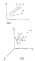
- the OTHR system 2 is also subject to multipath propagation in that there is more than one single path for echoes returned from a target due to a number of different ionospheric layers 54 at different heights 53 which refract echoes down to the receiving system 4, as shown in Figure 3.
- Propagation modes are described by the layers from which the signal is refracted. For example, F 0 - F 1 is the propagation mode for a transmit path via layer F 0 and a receive path via layer F 1 , where T represents the target 3, as shown in Figure 3.
- the height of the different layers can be determined using commercial ionospheric sounders which provides some information concerning the relationship between points of different propagation modes for the same target. Knowing the heights and properties of each layer gives an indication as to expected RAD measurements of different propagation modes.
- x ( k + 1) F ( k ) x ( k ) + v ( k )
- F(k) is a known matrix, for instance in the case of a constant velocity target where T k is the time between dwells k and k +1.
- v(k) represents zero-mean, white Gaussian process noise as used in standard Kalman filtering.
- the covariance matrix Q ( k ) of v(k) is assumed to be known.
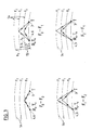
- a currently used tracking method based on the probabilistic data association (PDA) filter, as described in Y. Bar-Shalom and T.E. Fortmann, "Tracking and Data Association", Academic Press, 1988, performs tracking in the radar coordinates R , D , A , A ⁇ , as illustrated in Figure 2.
- a track is initiated by selection of a single, noisy measurement 50 with the unknown azimuth rate A ⁇ being initially set to correspond with a hypothesised azimuth crossing rate, usually zero. Further measurement selection is accomplished by taking only those measurements which fall inside a validation gate 70 around the next expected position of the target measurement. This method does not require knowledge of the mapping of radar to ground coordinates during tracking.
- a disadvantage of this method is that it fails to use the information conveyed by multiple detections arising from multipath propagation. Also the presence of multipath propagation may cause multiple tracks 60, 62 and 64 to be generated for a single target, as shown in Figure 4, when tracking is performed in radar coordinates using conventional filters such as PDA. If the tracks 62 and 64 closely conform with the expected separations for the hypothesised modes, they can be considered to relate to the same target 52 of Figure 5, whereas a track 66 which diverges excessively can be dismissed as corresponding to another target or to clutter. Such a situation, commonly arising in conventional PDA tracking, requires a fusion or clustering operation to group multimode tracks pertaining to the same target together. This allows a track to be identified with a particular propagation mode. A further stage of coordinate registration is then required to map the tracks to ground coordinates for geographical display to the radar operators.
- the preferred embodiment described herein uses explicit knowledge of the ionospheric structure including virtual heights, as provided by ionospheric sounders or by other means, to account for and take advantage of multipath propagation during track initiation and tracking. This is distinct from conventional approaches which only expect a single detection per target and are unable to benefit from the additional target-related information conveyed by multipath detections.
- the gain in tracking performance arising from multipath detections of a single target is important when the probability of target detection via some or all of the various propagation modes is low.
- the target state is taken to be as in equation (1), where r is the ground range 8 across the surface of the earth 9, a is the true azimuth, r ⁇ is the ground range rate and a ⁇ is the true azimuth rate.
- Tracking is performed in ground coordinates, although other frames of reference, for instance a preferred propagation mode, may be used to describe the target dynamics and relate these to the other measurement coordinates.
- the conversion between the ground and radar coordinates can be represented as where, at time k, R is the measured slant range, A the measured azimuth, D the Doppler speed (slant range rate), h r the virtual ionospheric height 53 on the receive path, and h t the virtual ionospheric height 54 on the transmit path, as shown in Figure 5.
- the slant range R may be defined as one half of the total path length from the transmitter 7 via the target 52 to the receiver 4.
- the measured azimuth or coning angle A is the complement of the angle A between the incoming ray 57 and the axis of receiver array axis 12.
- the Doppler speed D is proportional to the rate of change of the total path length.
- the various propagation modes can be labelled according to the corresponding outbound and return propagation mode combination F 0 - F 0 , F 0 - F 1 , F 1 - F 0 , ..., F 2 - F 2 for a target 52, as shown in Figure 3.
- F 0 , F 1 , F 2 , F 3 with heights h 0 , h 1 , h 2 , h 3 , these modes may be numbered from 1 to 16 respectively.
- the assumed number of possible propagation modes n may vary with time.
- w i (k) is a zero-mean, white Gaussian sequence with known covariance R i ( k ) representing the assumed measurement noise terms.
- H i ( ⁇ ) The actual form of the non-linear measurement functions H i ( ⁇ ) above is determined by the geometry of the ionospheric model as shown in Figure 5, and will depend on the virtual heights of the ionospheric layers h r and h t 53 and 55, and the location and separation of the receiver and transmitter arrays 7 and 12, among other factors.
- state prediction and associated prediction covariance are denoted by x and(k
- tracking is initiated by selecting an initial point 50 which may correspond to a hitherto unobserved target. Since the propagation mode which gave rise to this measurement is a priori unknown, an initial target state estimate x and (0
- the preferred method is therefore to initialise n tracking filters, one for each possible initial propagation mode. Each filter assumes a particular initial propagation mode with corresponding virtual heights h r and h t in order to assign its initial state estimate using equation (9) based on the first measurement point 50.
- the estimate of the initial target azimuth rate is set to some starting value, usually zero.
- 0) is also assigned and is taken to be large enough to cover the initial uncertainty in target position and velocity.
- Other methods of initialisation are possible using data from more than a single radar dwell; but the previously described method is the simplest among these.
- the filter based on the correct initial propagation mode assumption can be expected to perform the best and thus its state estimates would be more accurate (in the sense of having smaller errors on average) than those of the other filters initiated with it.
- the state estimates which, if any, of the n filters initiated as above is compatible with a target whose dynamical model is assumed to be as expressed in equation (2).
- the recursive processing required by each tracking filter, initialised as above, is now described.
- the aim of the processing is to compute, in a recursive manner, approximate conditional mean x and ( k
- the estimated target track is provided by plotting the range and azimuth values from x and ( k
- the accuracy of the track is indicated by the size of the standard deviations which can be obtained from the state error covariance P ( k
- the dynamical target model of equation (3) is used to predict where each measurement would appear during the next dwell in the absence of measurement noise under each propagation mode.
- 0) at time 1 is given, in the usual manner of Kalman filtering, as described in Y. Bar-Shalom and T.E. Fortmann, "Tracking and Data Association", Academic Press, 1988, as x (1
- 0) F (0) x (0
- 0) F (0) P (0
- n gates 72, 74 and 76 are used to generate n gates 72, 74 and 76 in the measurement space for each tracking filter, corresponding to the respective propagation modes F 0 - F 0 , F 0 - F 1 , ..., etc., as shown in Figure 6.
- the measurement predictions for the respective propagation modes are therefore
- the associated measurement prediction covariances are where J i (1) is the Jacobian matrix of the non-linear measurement function H i ( ⁇ ) in equation (6) evaluated at the state prediction x and (1
- the validation gate for each propagation mode is an ellipsoidal region in RAD space defined by where ⁇ i defines the size of the validation gate.
- the probability that a target falls inside the gate i is denoted P i / G, while the probability of detecting a target via the ith propagation mode is denoted P i / D.
- P i / G The probability that a target falls inside the gate i is denoted P i / G, while the probability of detecting a target via the ith propagation mode is denoted P i / D.
- the gates may or may not overlap.
- the validation region is defined as the union of the validation gates or some region which includes their union. Points which fall inside the validation gates are accepted as possibly relating to the target 52 and are used together with the state prediction x and (1
- This process is recursive and can be represented as follows:
- k ) is an approximate minimum-mean-square-error estimate of the target state x ( k ) based on all the information 48 from dwells 0 through k of the form given in Figure 2 including multiple detections of the same target due to multipath propagation.
- the estimate is approximate because it assumes that the probability density function of the true target state is Gaussian conditioned on all the measurement data.
- the measurements falling within the gates 72, 74, 76, etc. are used in a probabilistic data association framework as described in Y. Bar-Shalom and T.E. Fortmann, "Tracking and Data Association", Academic Press, 1988, which, in addition to consideration of a measurement being from a target or due to clutter, includes association hypotheses for the possible propagation modes which may have produced the measurements.
- a target existence or confidence model is also incorporated in the filter as described in S.B. Colegrove, A.W. Davis and J.K. Ayliffe, "Track Initiation and Nearest Neighbours Incorporated into Probabilistic Data Association", J.
- Target existence is modelled as a 2-state Markov Chain so that the predicted probability of target existence P E ( k
- k - 1) ⁇ 0 P E ( k - 1
- k - 1) ⁇ where the two transition probabilities ⁇ 0 and ⁇ 1 are defined by ⁇ 0 Pr (target exists at time k
- target exists at time k - 1) ⁇ 1 Pr (target exists at time k
- 0) 0.5 is assumed.
- k ) can be formed from the predicted state estimate x and ( k
- association probability The computation of the probability of each associated hypothesis, called the association probability, can be illustrated by assuming uniformly distributed clutter measurements in the radar measurement space, and a Poisson model, as described in Y. Bar-Shalom and T.E. Fortmann, "Tracking and Data Association", Academic Press, 1988, with spatial density ⁇ for the number of clutter points inside the validation region. Also, we let the probability of target detection P D via any propagation mode be identical, and the gate probabilities P G be identical. P D and P G are parameters that are given values which are selected to extract optimum performance from the tracking method given the operating characteristics of the system 2.
- the updated target state estimate for the filter is obtained by summing the conditional state estimates with weightings determined by their respective association probabilities as
- k ) is obtained using standard techniques from Gaussian mixtures described in Y. Bar-Shalom and T.E. Fortmann, "Tracking and Data Association", Academic Press, 1988 as
- Track maintenance is achieved by thresholding the target existence probability according to where P DEL and P CON are the track maintenance thresholds. Note P DEL ⁇ P CON . Since P E ( k
- a tracking filter as described above has been implemented in software using the C programming language and executed on a Digital Equipment Corporation 175 MHz Alpha workstation.
- the preferred implementation assumes 4 propagation modes corresponding to F 0 - F 0 , F 0 -F 1 , F 1 - F 0 and F 1 - F 1 .
- the virtual heights of the F 0 and F 1 ionospheric layers are included as state variables in equation (7) and these are estimated from noisy measurements along with the range, azimuth, range rate and azimuth rate of the target.
Abstract
Description
- The present invention relates to a tracking method for a radar system, such as a phased array radar system or a bistatic radar system. Although the following discusses use for radar systems, the invention could also be applied to other signal echo systems, such as sonar systems.
- Radar signals returned from a target allow information to be determined concerning the slant range, azimuth and speed of a target relative to the receiving system of the radar system. The receiving system however normally receives a number of signals returned from the target which have different propagation paths or modes. Noise received by and induced in the receiving system can also be mistaken for a return signal from the target and needs to be taken into account. Tracking methods have been employed which track a target on the basis of signals relating to one propagation mode. Yet selecting one propagation mode neglects information relating to other modes which can be used to enhance the accuracy and sensitivity of the tracking method.
- In accordance with the present invention there is provided a tracking method for a signal echo system, as said forth in claims 1 and 10.
- Advantageous aspects of the invention are set out in the appendant claims.
- A preferred embodiment of the present invention is hereinafter described, by way of example only, with reference to the accompanying drawings, wherein:
- Figure 1 is a schematic diagram of an over the horizon radar (OTHR) system;
- Figure 2 is a diagram of a measurement frame of reference;
- Figure 3 is a diagram of possible propagation modes;
- Figure 4 is a graph of target tracks;
- Figure 5 is a diagram of measurement geometry of the system; and
- Figure 6 is a diagram of multiple gates for target state estimation.
-
- Bistatic radar systems employ separate transmitter and receiver sites, and include Over The Horizon Radar (OTHR) systems which direct transmission signals above the horizon for refraction by the ionosphere, known as skywave systems. OTHR systems also include surface wave radar systems which propagate radar waves along the surface of saltwater, and rely on the receiving system being able to detect objects by the radar signals reflected therefrom.
- An OTHR system 2, as shown in Figure 1, includes a receiving system 4 and a transmitting system 6. The transmitting system 6 comprises an in-line array 7 of transmitting antennas located at the transmitter site and a control system 10 for feeding electrical signals to the antennas. The receiving system 4 comprises an in-line array 12 of receiving antennas and a control system 16 for processing the signals received by the antennas, which are located at the receiver site. OTHR systems include the Jindalee Facility in Alice Springs (JFAS) and the U.S. Navy's ROTHR system.
- The broad transmitting beam of the radar is directed towards areas of the ionosphere from which refracted signals are redirected to monitor a target 3. The beam is effectively directed to a region or area in which a target is located. A number of targets may be located in one region and the receiver control system 16 is able to divide the energy returned from the illuminated region into a dozen smaller beams which can then each be divided into a plurality of range cells that are characterised by a respective distance from the receiving system 4. This allows the receiving system 4 to track a number of targets which are located in the illuminated region. The receive beams can also be divided into a plurality of velocity cells characterised by an object's velocity relative to the receiving system 4. This allows targets to be separated on the basis of their velocity if they cannot be separated on the basis of their distance from the receiving system 4. The transmitting and receiving beams can be moved or swept in synchronism, through a number of beam steer positions, with the time being spent at any given position being referred to as the dwell time. Measurements obtained from the radar signals or echoes received during each dwell time are referred to as dwells.
- The control software of the control system 16 is able to obtain four parameters pertaining to a target from each dwell, and these are the propagation path length or slant range (R), azimuth (A), Doppler frequency shift or radial speed (D) and signal strength based on a signal to noise ratio (SNR) measurement. These are referred to as the RAD or radar coordinates. The set of measurements from a dwell also includes clutter and detections from other targets.
- The dwells can be graphically represented by plotting them as candidate detection points on a three dimensional axis, as shown in Figure 2, for dwell t = k, where one axis represents R, the other A and the third the D values. For any dwell time t = k of the order of 100 or 1000 candidate detection points 50 may be determined by the receiving system 4. Some of the points 50 may correspond to a target and others may simply relate to clutter echoes or noise intrinsic in the transmitting system 6 or receiving system 4. Clutter echoes arise from backscatter from the ground or objects which are not of interest, such as meteors. The OTHR system 2 is also subject to multipath propagation in that there is more than one single path for echoes returned from a target due to a number of different ionospheric layers 54 at different heights 53 which refract echoes down to the receiving system 4, as shown in Figure 3. There may be up to four different reflecting layers F 0, F 1, F 2 and F 3 resulting in several echoes returned from a target, corresponding to reflections from combinations of these layers. Propagation modes are described by the layers from which the signal is refracted. For example, F 0-F 1 is the propagation mode for a transmit path via layer F 0 and a receive path via layer F 1, where T represents the target 3, as shown in Figure 3. Whilst the propagation path for a candidate detection point 50 is not known, the height of the different layers can be determined using commercial ionospheric sounders which provides some information concerning the relationship between points of different propagation modes for the same target. Knowing the heights and properties of each layer gives an indication as to expected RAD measurements of different propagation modes.
- The state of the target, at a given dwell k, can be represented bywhere r is the range, a the azimuth, r ˙ the range rate and .a the azimuth rate. Equations of motion can be used to describe the target dynamics, for example, a constant velocity target would, if the time T between dwells were constant, obey
 where Tk is the time between dwells k and k+1. The term v(k) represents zero-mean, white Gaussian process noise as used in standard Kalman filtering. The covariance matrix Q(k) of v(k) is assumed to be known.
- A currently used tracking method, based on the probabilistic data association (PDA) filter, as described in Y. Bar-Shalom and T.E. Fortmann, "Tracking and Data Association", Academic Press, 1988, performs tracking in the radar coordinates R, D, A, A ˙, as illustrated in Figure 2. A track is initiated by selection of a single, noisy measurement 50 with the unknown azimuth rate A ˙ being initially set to correspond with a hypothesised azimuth crossing rate, usually zero. Further measurement selection is accomplished by taking only those measurements which fall inside a validation gate 70 around the next expected position of the target measurement. This method does not require knowledge of the mapping of radar to ground coordinates during tracking. A disadvantage of this method is that it fails to use the information conveyed by multiple detections arising from multipath propagation. Also the presence of multipath propagation may cause multiple tracks 60, 62 and 64 to be generated for a single target, as shown in Figure 4, when tracking is performed in radar coordinates using conventional filters such as PDA. If the tracks 62 and 64 closely conform with the expected separations for the hypothesised modes, they can be considered to relate to the same target 52 of Figure 5, whereas a track 66 which diverges excessively can be dismissed as corresponding to another target or to clutter. Such a situation, commonly arising in conventional PDA tracking, requires a fusion or clustering operation to group multimode tracks pertaining to the same target together. This allows a track to be identified with a particular propagation mode. A further stage of coordinate registration is then required to map the tracks to ground coordinates for geographical display to the radar operators.
- The preferred embodiment described herein uses explicit knowledge of the ionospheric structure including virtual heights, as provided by ionospheric sounders or by other means, to account for and take advantage of multipath propagation during track initiation and tracking. This is distinct from conventional approaches which only expect a single detection per target and are unable to benefit from the additional target-related information conveyed by multipath detections. The gain in tracking performance arising from multipath detections of a single target is important when the probability of target detection via some or all of the various propagation modes is low.
- The target state is taken to be as in equation (1), where r is the ground range 8 across the surface of the earth 9, a is the true azimuth, r ˙ is the ground range rate and a ˙ is the true azimuth rate. The true azimuth a is the complement of the angle
a , which is the angle between the projected ground range r and the axis of the receiver array 12, as shown in Figure 5, i.e. a = (90° -a ). Tracking is performed in ground coordinates, although other frames of reference, for instance a preferred propagation mode, may be used to describe the target dynamics and relate these to the other measurement coordinates. - The conversion between the ground and radar coordinates can be represented aswhere, at time k, R is the measured slant range, A the measured azimuth, D the Doppler speed (slant range rate), hr the virtual ionospheric height 53 on the receive path, and ht the virtual ionospheric height 54 on the transmit path, as shown in Figure 5. The slant range R may be defined as one half of the total path length from the transmitter 7 via the target 52 to the receiver 4. The measured azimuth or coning angle A is the complement of the angle

A between the incoming ray 57 and the axis of receiver array axis 12. The Doppler speed D is proportional to the rate of change of the total path length. - The various propagation modes can be labelled according to the corresponding outbound and return propagation mode combination F 0-F 0, F 0-F 1, F 1-F 0, ..., F 2-F 2 for a target 52, as shown in Figure 3. For four possible ionospheric layers F 0, F 1, F 2, F 3 with heights h 0, h 1, h 2, h 3, these modes may be numbered from 1 to 16 respectively. Hence we may write the measurement process for the various propagation modes in terms of the target state x(k) aswhere H 1(x(k)) = H(r(k), a(k), r ˙(k); h 0, h 0), H 2(x(k)) = H(r(k), a(k), r ˙(k); h 0, h 1), etc., and the assumed number of possible propagation modes n may vary with time. In the above, wi(k) is a zero-mean, white Gaussian sequence with known covariance Ri (k) representing the assumed measurement noise terms. The actual form of the non-linear measurement functions Hi (·) above is determined by the geometry of the ionospheric model as shown in Figure 5, and will depend on the virtual heights of the ionospheric layers hr and ht 53 and 55, and the location and separation of the receiver and transmitter arrays 7 and 12, among other factors.

- Since the virtual ionospheric heights hi in Figure 5 may only be approximately known, but are assumed to vary slowly in comparison with the target dynamics, they can be included in the state vector x(k) and estimated along with the dynamical variables describing the target. In this case we have instead of equation (1)with each virtual height satisfying an equation of the form

- Converting to the ground frame of reference requires the selection of an outbound and return propagation mode combination Ft and Fr with corresponding virtual heights ht and hr. The inverse transformation to equation (5) can be represented byand follows from the assumed geometry indicated in Figure 5.

- Hereinafter the state prediction and associated prediction covariance are denoted by x and(k|k - 1) and P(k|k - 1) and an updated state estimate and state error covariance are denoted by x and (k|k) and P(k|k).
- At some arbitrary time 0, tracking is initiated by selecting an initial point 50 which may correspond to a hitherto unobserved target. Since the propagation mode which gave rise to this measurement is a priori unknown, an initial target state estimate x and (0|0) for equation (1) cannot be inferred from equation (9) unless a given propagation mode, or equivalently the ionospheric heights for the transmit and receive paths, is assumed. The preferred method is therefore to initialise n tracking filters, one for each possible initial propagation mode. Each filter assumes a particular initial propagation mode with corresponding virtual heights hr and ht in order to assign its initial state estimate using equation (9) based on the first measurement point 50. The estimate of the initial target azimuth rate is set to some starting value, usually zero. An initial state error covariance P(0|0) is also assigned and is taken to be large enough to cover the initial uncertainty in target position and velocity. Other methods of initialisation are possible using data from more than a single radar dwell; but the previously described method is the simplest among these. Of the n filters initiated from the measurement 50, the filter based on the correct initial propagation mode assumption can be expected to perform the best and thus its state estimates would be more accurate (in the sense of having smaller errors on average) than those of the other filters initiated with it. As the processing proceeds, it becomes clear by observation of the state estimates which, if any, of the n filters initiated as above is compatible with a target whose dynamical model is assumed to be as expressed in equation (2).
- The recursive processing required by each tracking filter, initialised as above, is now described. The aim of the processing is to compute, in a recursive manner, approximate conditional mean x and(k|k) and covariance P(k|k) estimates of the target state, based on the measurement data, including virtual ionospheric height measurements, up to time k, Y(1), ..., Y(k), where Y(i) represents the set of measurements received in dwell i. The estimated target track is provided by plotting the range and azimuth values from x and(k|k). The accuracy of the track is indicated by the size of the standard deviations which can be obtained from the state error covariance P(k|k).
- The dynamical target model of equation (3) is used to predict where each measurement would appear during the next dwell in the absence of measurement noise under each propagation mode. The state prediction x and(1|0) at time 1 is given, in the usual manner of Kalman filtering, as described in Y. Bar-Shalom and T.E. Fortmann, "Tracking and Data Association", Academic Press, 1988, asThe associated measurement prediction covariances are
 where Ji (1) is the Jacobian matrix of the non-linear measurement function Hi (·) in equation (6) evaluated at the state prediction x and(1|0). The validation gate for each propagation mode is an ellipsoidal region in RAD space defined by
 where γ i defines the size of the validation gate. The probability that a target falls inside the gate i is denoted P i / G, while the probability of detecting a target via the ith propagation mode is denoted P i / D. This is illustrated in Figure 6 for three gates 72, 74 and 76 centred on measurement predictions 82, 84 and 86 for three propagation modes F 0-F 0, F 0-F 1, ..., etc. The gates may or may not overlap. The validation region is defined as the union of the validation gates or some region which includes their union. Points which fall inside the validation gates are accepted as possibly relating to the target 52 and are used together with the state prediction x and(1|0) in order to update the state estimate x and(0|0) to yield x and(1 |1). The corresponding state error covariance is also updated to P(1|1). This process is recursive and can be represented as follows:

- The state estimate x and(k|k) is an approximate minimum-mean-square-error estimate of the target state x(k) based on all the information 48 from dwells 0 through k of the form given in Figure 2 including multiple detections of the same target due to multipath propagation. The estimate is approximate because it assumes that the probability density function of the true target state is Gaussian conditioned on all the measurement data.
- To determine the updated target state x and(k|k) and its covariance P(k|k), the measurements falling within the gates 72, 74, 76, etc. are used in a probabilistic data association framework as described in Y. Bar-Shalom and T.E. Fortmann, "Tracking and Data Association", Academic Press, 1988, which, in addition to consideration of a measurement being from a target or due to clutter, includes association hypotheses for the possible propagation modes which may have produced the measurements. A target existence or confidence model is also incorporated in the filter as described in S.B. Colegrove, A.W. Davis and J.K. Ayliffe, "Track Initiation and Nearest Neighbours Incorporated into Probabilistic Data Association", J. Elec. and Electronic Eng., Australia, Vol. 6, No. 3, pp. 191-198, 1986, to aid in track maintenance (confirmation, deletion, etc.). The probability that the target exists at time k given data to time k is denoted PE (k|k). Target existence is modelled as a 2-state Markov Chain so that the predicted probability of target existence PE (k|k - 1) satisfies
Δ0 = Pr(target exists at time k|target exists at time k - 1)
Δ1 = Pr(target exists at time k|target does not exist at time k - 1)
An arbitrary initial value of PE (0|0) = 0.5 is assumed. - As an illustration of the filtering procedure, consider gates 72 and 74 associated with propagation modes F 0-F 0 and F 0-F 1, and gate 76 associated with propagation mode F 1-F 1, with respective centres given by the measurement predictions y and 1(k|k - 1), y and 2(k|k - 1) and y and 3(k|k - 1), 82, 84 and 86. We will number these propagation modes as 1, 2 and 3, respectively when referring to the measurement predictions. Suppose that the gate 72 contains two measurements y 1, y 2 90 and that gate 74 contains one measurement y 3 92, while gate 76 does not contain any measurements. The 7 association hypothesis (numbered from -1 to 5) which can be applied are:
- (-1) The target does not exist.
- (0) The target exists but all validated measurements y 1, y 2 and y 3 are clutter.
- (1) y 1 and y 3 are clutter, y 2 is a target detection via propagation mode F 0-F 0.
- (2) y 2 and y 3 are clutter, y 1 is a target detection via propagation mode F 0-F 0.
- (3) y 3 is a target detection via F 0-F 1 and both y 1 and y 2 are clutter.
- (4) y 3 is a target detection via F 0 -F 1, y 1 is a target detection via F 0-F 0 and y 2 is clutter.
- (5) y 3 is a target detection via F 0-F 1, y 2 is a target detection via F 0-F 0 and y 1 is clutter.
-
- For each of the possible associated hypothesis above, a conditional target state estimate x andi (k|k) can be formed from the predicted state estimate x and(k|k - 1) using the extended Kalman filter theory, as described in G.W. Pulford and R.J. Evans, "Probabilistic Data Association for Systems with Multiple Simultaneous Measurements", Automatica, Vol. 32, No. 9, pp. 1311-1316, 1996. Omitting some time indexes and writing
x = x and(k|k - 1) for equation (10),P = P(k|k - 1) for equation (11), andy i = y andi (k|k - 1) for equation (12), the conditional state estimates in this case are given bywhere the terms Ji and Si are as in equation (13). The corresponding conditional state error covariances Pi (k|k) are given by where c ≥ 1 is a scaling factor reflecting the increased uncertainty in the case that the target does not exist.
- The computation of the probability of each associated hypothesis, called the association probability, can be illustrated by assuming uniformly distributed clutter measurements in the radar measurement space, and a Poisson model, as described in Y. Bar-Shalom and T.E. Fortmann, "Tracking and Data Association", Academic Press, 1988, with spatial density λ for the number of clutter points inside the validation region. Also, we let the probability of target detection PD via any propagation mode be identical, and the gate probabilities PG be identical. PD and PG are parameters that are given values which are selected to extract optimum performance from the tracking method given the operating characteristics of the system 2. The association probabilities β i (k), defined as the probability of the respective association hypothesis i conditioned on all measurement data up to the current time k, can be expressed as described in G.W. Pulford and R.J. Evans, "Probabilistic Data Association for Systems with Multiple Simultaneous Measurements", Automatica, Vol. 32, No. 9, pp. 1311-1316, 1996, by:
y , S} is a multivariate Gaussian density in y with meany and covariance S, and δ(k) is a normalisation constant, chosen to ensure that the association probabilities sum to unity. - The updated target state estimate for the filter is obtained by summing the conditional state estimates with weightings determined by their respective association probabilities asThe state error covariance P(k|k) is obtained using standard techniques from Gaussian mixtures described in Y. Bar-Shalom and T.E. Fortmann, "Tracking and Data Association", Academic Press, 1988 as


- The updated probability of target existence PE (k|k) is obtained as
- Track maintenance is achieved by thresholding the target existence probability according towhere PDEL and PCON are the track maintenance thresholds. Note PDEL < PCON. Since PE (k|k) may vary considerably from dwell to dwell, it is better to use the average value of PE (k|k) over the last few dwells for track confirmation in equation (23).

- The above method is easily extended to arbitrary numbers of measurements falling inside the validation gates and to arbitrary numbers of propagation modes. Arbitrary clutter probability density functions and non-identical gate and detection probabilities are also easily accommodated within this framework.
- A tracking filter as described above has been implemented in software using the C programming language and executed on a Digital Equipment Corporation 175 MHz Alpha workstation. The preferred implementation assumes 4 propagation modes corresponding to F 0-F 0, F 0 -F 1, F 1-F 0 and F 1-F 1. The virtual heights of the F 0 and F 1 ionospheric layers are included as state variables in equation (7) and these are estimated from noisy measurements along with the range, azimuth, range rate and azimuth rate of the target.
Claims (10)
- A tracking method for a signal echo system, including:generating a plurality of gates for respective multipath propagation modes on the basis of a target state prediction for a dwell time; andgenerating a target state estimate for said dwell time on the basis of target measurement points which fall within said gates.
- A tracking method as claimed in claim 1, including:obtaining initial target measurement points for an initial dwell time;initiating tracking by obtaining an initial target state estimate from at least one of said initial points; anddetermining said target state prediction for a dwell time subsequent to said initial time on the basis of said initial target state estimate.
- A tracking method as claimed in claim 2, wherein a target state estimate is generated by applying association hypotheses to said measurement points in said gates and association probabilities to said hypotheses, obtaining conditional state estimates from the measurement points for each hypothesis and summing said conditional state estimates multiplied by said probabilities.
- A tracking method as claimed in claim 3, wherein the probability of existence PE of a target track is obtained from at least one of said association probabilities and if PE is less than a predetermined threshold a target track maintained using said target state estimate is deleted.
- A tracking method as claimed in claim 4, wherein said measurement points are candidate detection points in RAD space obtained from dwells.
- A tracking method as claimed in claim 5, wherein said target state prediction is obtained from said target state estimate using linear equations of motion.
- A tracking method as claimed in claim 6, wherein said gates are validation gates having an ellipsoidal shape in RAD space and obtained by transposing said target state prediction to RAD space for respective propagation modes to obtain measurement predictions and associated prediction covariances for respective propagation modes defining said validation gates.
- A tracking method as claimed in claim 7, wherein said hypotheses include target does not exist, the measurement points in said gates represent clutter, and a measurement point in at least one of said gates represents a target detection.
- A tracking method as claimed in any one of claims 2 to 8, wherein the tracking initiating step is performed for a plurality of propagation modes to initiate a plurality of tracking filters by generating a plurality of said initial target state estimates.
- A tracking method for a signal echo system, including extending a target state vector to include additional parameters associated with a plurality of multipath propagation modes, generating a plurality of gates for said propagation modes, on the basis of a target state prediction for a dwell time and accounting for measurement uncertainty associated with propagation path characteristics for said modes when updating target state estimates for the dwell time on the basis of measurements which fall within said gates.
Priority Applications (1)
| Application Number | Priority Date | Filing Date | Title |
|---|---|---|---|
| SI9630495T SI0868669T1 (en) | 1995-12-19 | 1996-12-19 | A tracking method for a radar system |
Applications Claiming Priority (4)
| Application Number | Priority Date | Filing Date | Title |
|---|---|---|---|
| AUPN7226A AUPN722695A0 (en) | 1995-12-19 | 1995-12-19 | A tracking method for a radar system |
| AUPN7226/95 | 1995-12-19 | ||
| AUPN722695 | 1995-12-19 | ||
| PCT/AU1996/000817 WO1997022889A1 (en) | 1995-12-19 | 1996-12-19 | A tracking method for a radar system |
Publications (3)
| Publication Number | Publication Date |
|---|---|
| EP0868669A1 EP0868669A1 (en) | 1998-10-07 |
| EP0868669A4 EP0868669A4 (en) | 1999-06-02 |
| EP0868669B1 true EP0868669B1 (en) | 2002-05-08 |
Family
ID=3791545
Family Applications (1)
| Application Number | Title | Priority Date | Filing Date |
|---|---|---|---|
| EP96942984A Expired - Lifetime EP0868669B1 (en) | 1995-12-19 | 1996-12-19 | A tracking method for a radar system |
Country Status (12)
| Country | Link |
|---|---|
| US (1) | US6243037B1 (en) |
| EP (1) | EP0868669B1 (en) |
| JP (1) | JP2000501839A (en) |
| AT (1) | ATE217421T1 (en) |
| AU (1) | AUPN722695A0 (en) |
| CA (1) | CA2240950C (en) |
| DE (1) | DE69621154T2 (en) |
| DK (1) | DK0868669T3 (en) |
| EA (1) | EA000517B1 (en) |
| ES (1) | ES2176519T3 (en) |
| PT (1) | PT868669E (en) |
| WO (1) | WO1997022889A1 (en) |
Cited By (1)
| Publication number | Priority date | Publication date | Assignee | Title |
|---|---|---|---|---|
| CN103760555A (en) * | 2014-01-23 | 2014-04-30 | 西安电子科技大学 | Method for improving airborne radar detection and tracking integration precision |
Families Citing this family (31)
| Publication number | Priority date | Publication date | Assignee | Title |
|---|---|---|---|---|
| US6694044B1 (en) * | 1999-09-16 | 2004-02-17 | Hewlett-Packard Development Company, L.P. | Method for motion classification using switching linear dynamic system models |
| US6993462B1 (en) | 1999-09-16 | 2006-01-31 | Hewlett-Packard Development Company, L.P. | Method for motion synthesis and interpolation using switching linear dynamic system models |
| US6591146B1 (en) * | 1999-09-16 | 2003-07-08 | Hewlett-Packard Development Company L.C. | Method for learning switching linear dynamic system models from data |
| US6683968B1 (en) | 1999-09-16 | 2004-01-27 | Hewlett-Packard Development Company, L.P. | Method for visual tracking using switching linear dynamic system models |
| GB2365239A (en) * | 2000-07-26 | 2002-02-13 | Alenia Marconi Systems Ltd | Near-vertical incidence skywave HF radar |
| US6877691B2 (en) * | 2002-03-12 | 2005-04-12 | Bae Systems Information And Electronic Systems Integration Inc. | High altitude stripping for threat discrimination |
| NL1020287C2 (en) * | 2002-04-02 | 2003-10-03 | Thales Nederland Bv | Method for multi-target detection, in particular for use in search radars with multi-beam formation in elevation. |
| AU2002952531A0 (en) * | 2002-11-06 | 2002-11-21 | Telstra Corporation Limited | A transmit antenna |
| AU2003277990B2 (en) * | 2002-11-06 | 2008-02-21 | Telstra Corporation Limited | A transmit antenna |
| US7218270B1 (en) * | 2003-02-10 | 2007-05-15 | The United States Of America As Represented By The Secretary Of The Air Force | ATR trajectory tracking system (A-Track) |
| JP4266669B2 (en) * | 2003-02-28 | 2009-05-20 | 日本電気株式会社 | Bistatic orientation detection system and detection method |
| US20050195102A1 (en) * | 2004-03-05 | 2005-09-08 | Vaman Dhadesugoor R. | Real time predictive trajectory pairing (RTPTP) algorithm for highly accurate tracking of ground or air moving objects |
| DE102004036580A1 (en) * | 2004-07-28 | 2006-03-16 | Robert Bosch Gmbh | Method and device for object detection in a vehicle |
| US7187320B1 (en) * | 2004-08-27 | 2007-03-06 | Lockheed Martin Corporation | Matched maneuver detector |
| US8089393B2 (en) * | 2006-06-13 | 2012-01-03 | Bae Systems Plc | Relating target tracking |
| US7675458B2 (en) * | 2006-11-09 | 2010-03-09 | Raytheon Canada Limited | Dual beam radar system |
| US7626535B2 (en) * | 2006-11-09 | 2009-12-01 | Raytheon Company | Track quality based multi-target tracker |
| GB0711531D0 (en) * | 2007-06-15 | 2007-07-25 | Qinetiq Ltd | Radar coordinate registration |
| FR2933497B1 (en) * | 2008-07-03 | 2012-06-01 | Claude Goutelard | METHODS AND SYSTEMS FOR CODED EMISSION AND ANTENNA RECEPTION, IN PARTICULAR FOR RADAR |
| US9240053B2 (en) * | 2010-03-15 | 2016-01-19 | Bae Systems Plc | Target tracking |
| GB201004232D0 (en) | 2010-03-15 | 2010-04-28 | Bae Systems Plc | Target tracking |
| US8976059B2 (en) | 2012-12-21 | 2015-03-10 | Raytheon Canada Limited | Identification and removal of a false detection in a radar system |
| US9507020B2 (en) * | 2013-12-05 | 2016-11-29 | Honeywell International Inc. | Unmanned aircraft systems sense and avoid sensor fusion track initialization |
| US10054668B2 (en) | 2015-02-26 | 2018-08-21 | Src, Inc. | Probabilistic signal, detection, and track processing architecture and system |
| CN104833967A (en) * | 2015-05-11 | 2015-08-12 | 重庆大学 | Radar target tracking method based on moving horizon estimation |
| US10126418B1 (en) * | 2015-09-08 | 2018-11-13 | Waymo LLP | Pulse-doppler rada measurement of crossing target dynamics |
| CN106093853B (en) * | 2016-06-07 | 2019-02-19 | 北京邮电大学 | The measurement method and device of location of mobile station |
| CN107728139B (en) * | 2017-09-12 | 2020-11-17 | 电子科技大学 | Phased array radar networking system resource management method based on multi-target tracking |
| CN108828568A (en) * | 2018-07-19 | 2018-11-16 | 中国人民解放军战略支援部队信息工程大学 | A kind of direct localization method and system of single moving observer |
| CN111487998B (en) * | 2020-04-13 | 2023-07-25 | 华中光电技术研究所(中国船舶重工集团公司第七一七研究所) | Automatic target capturing method and device for two-axis four-frame photoelectric tracking equipment |
| CN117214857B (en) * | 2023-11-09 | 2024-02-02 | 中国人民解放军海军航空大学 | Tracking method of Gaussian multi-hypothesis multi-expansion target in three-dimensional scene |
Family Cites Families (14)
| Publication number | Priority date | Publication date | Assignee | Title |
|---|---|---|---|---|
| US3731304A (en) * | 1961-09-08 | 1973-05-01 | Us Navy | Track-before-detect system |
| FR2098514A5 (en) * | 1970-07-09 | 1972-03-10 | Thomson Csf | |
| US4005415A (en) * | 1975-03-31 | 1977-01-25 | The United States Of America As Represented By The Secretary Of The Navy | Automated radar data processing system |
| US5001650A (en) * | 1989-04-10 | 1991-03-19 | Hughes Aircraft Company | Method and apparatus for search and tracking |
| AU647639B2 (en) * | 1991-07-18 | 1994-03-24 | Commonwealth Of Australia, The | Track initiation and use of signal strength |
| US5202691A (en) * | 1992-04-28 | 1993-04-13 | The United States Of America As Represented By The Secretary Of The Air Force | Hick's probabilistic data association method |
| US5313212A (en) * | 1992-10-19 | 1994-05-17 | Hughes Aircraft Company | Track filter bias estimation |
| US5400264A (en) * | 1993-04-29 | 1995-03-21 | International Business Machines Corporation | Suboptimal joint probabilistic data association |
| US5414643A (en) * | 1993-06-14 | 1995-05-09 | Hughes Aircraft Company | Method and apparatus for continuous time representation of multiple hypothesis tracking data |
| SE515200C2 (en) * | 1993-11-17 | 2001-06-25 | Ericsson Telefon Ab L M | Distance Determination Procedure |
| US5537119A (en) * | 1993-12-21 | 1996-07-16 | Colorado State University Research Foundation | Method and system for tracking multiple regional objects by multi-dimensional relaxation |
| US5379044A (en) * | 1993-12-23 | 1995-01-03 | Hughes Aircraft Company | Efficient multi-target tracking method |
| US5798942A (en) * | 1994-04-05 | 1998-08-25 | Trw Inc. | N-best feasible hypotheses multitarget tracking system for space-based early warning systems |
| US5940523A (en) * | 1996-03-19 | 1999-08-17 | University Corporation For Atmospheric Research | Method of moment estimation and feature extraction for devices which measure spectra as a function of range or time |
-
1995
- 1995-12-19 AU AUPN7226A patent/AUPN722695A0/en not_active Abandoned
-
1996
- 1996-12-19 CA CA002240950A patent/CA2240950C/en not_active Expired - Fee Related
- 1996-12-19 US US09/117,584 patent/US6243037B1/en not_active Expired - Fee Related
- 1996-12-19 DE DE69621154T patent/DE69621154T2/en not_active Expired - Fee Related
- 1996-12-19 EA EA199800582A patent/EA000517B1/en not_active IP Right Cessation
- 1996-12-19 DK DK96942984T patent/DK0868669T3/en active
- 1996-12-19 PT PT96942984T patent/PT868669E/en unknown
- 1996-12-19 JP JP09522365A patent/JP2000501839A/en not_active Ceased
- 1996-12-19 EP EP96942984A patent/EP0868669B1/en not_active Expired - Lifetime
- 1996-12-19 WO PCT/AU1996/000817 patent/WO1997022889A1/en active IP Right Grant
- 1996-12-19 AT AT96942984T patent/ATE217421T1/en not_active IP Right Cessation
- 1996-12-19 ES ES96942984T patent/ES2176519T3/en not_active Expired - Lifetime
Cited By (2)
| Publication number | Priority date | Publication date | Assignee | Title |
|---|---|---|---|---|
| CN103760555A (en) * | 2014-01-23 | 2014-04-30 | 西安电子科技大学 | Method for improving airborne radar detection and tracking integration precision |
| CN103760555B (en) * | 2014-01-23 | 2016-05-18 | 西安电子科技大学 | A kind of method that improves airborne radar detection Tracking Integrative precision |
Also Published As
| Publication number | Publication date |
|---|---|
| AUPN722695A0 (en) | 1996-03-14 |
| ATE217421T1 (en) | 2002-05-15 |
| DE69621154D1 (en) | 2002-06-13 |
| WO1997022889A1 (en) | 1997-06-26 |
| CA2240950C (en) | 2005-02-15 |
| DE69621154T2 (en) | 2002-12-12 |
| EP0868669A1 (en) | 1998-10-07 |
| EP0868669A4 (en) | 1999-06-02 |
| EA199800582A1 (en) | 1998-12-24 |
| PT868669E (en) | 2002-09-30 |
| JP2000501839A (en) | 2000-02-15 |
| CA2240950A1 (en) | 1997-06-26 |
| ES2176519T3 (en) | 2002-12-01 |
| DK0868669T3 (en) | 2002-07-01 |
| EA000517B1 (en) | 1999-10-28 |
| US6243037B1 (en) | 2001-06-05 |
Similar Documents
| Publication | Publication Date | Title |
|---|---|---|
| EP0868669B1 (en) | A tracking method for a radar system | |
| Pulford et al. | A multipath data association tracker for over-the-horizon radar | |
| Stone et al. | Bayesian multiple target tracking | |
| Yeddanapudi et al. | IMM estimation for multitarget-multisensor air traffic surveillance | |
| US20100109938A1 (en) | Adaptive radar | |
| US5949364A (en) | Method and system for producing images of an object | |
| Pulford | OTHR multipath tracking with uncertain coordinate registration | |
| US11073608B2 (en) | Resolving radar angle ambiguities using a multiple hypothesis tracker | |
| Anderson et al. | Track association for over-the-horizon radar with a statistical ionospheric model | |
| Liu et al. | Practical moving target detection in maritime environments using fuzzy multi-sensor data fusion | |
| WO1996035962A1 (en) | Phased array radar system for tracking | |
| Ristic et al. | Gaussian mixture multitarget–multisensor Bernoulli tracker for multistatic sonobuoy fields | |
| AU708370B2 (en) | A tracking method for a radar system | |
| Schuster et al. | Multi Detection Joint Integrated Probabilistic Data Association Using Random Matrices with Applications to Radar-Based Multi Object Tracking. | |
| EP0323688A1 (en) | Tracking systems | |
| Schuster et al. | Target tracking in marine environment using automotive radar and laser range sensor | |
| Musicki et al. | Target existence based mht | |
| Baek et al. | Grid-based target estimation scheme for passive coherent location system | |
| KR102263541B1 (en) | Multistatic radar system and initial setting method of target thereof | |
| Davey et al. | A unified joint probabilistic data association filter with multiple models | |
| McIntyre et al. | Data association in passive acoustic tracking | |
| White et al. | Association of Over-The-Horizon radar tracks with tracks from microwave radar and other sources | |
| Bowman | Data integration (fusion) tree paradigm | |
| Pulford et al. | Integrated Multipath Track Initiation for Over-the-Horizon Radar | |
| Zhuk et al. | Adaptive Radar Tracking Algorithm for Maneuverable UAV with Probabilistic Identification of Data Using Coordinate and Amplitude Characteristics |
Legal Events
| Date | Code | Title | Description |
|---|---|---|---|
| PUAI | Public reference made under article 153(3) epc to a published international application that has entered the european phase |
Free format text: ORIGINAL CODE: 0009012 |
|
| 17P | Request for examination filed |
Effective date: 19980709 |
|
| AK | Designated contracting states |
Kind code of ref document: A1 Designated state(s): AT BE CH DE DK ES FI FR GB GR IE IT LI LU MC NL PT SE |
|
| A4 | Supplementary search report drawn up and despatched |
Effective date: 19990416 |
|
| AK | Designated contracting states |
Kind code of ref document: A4 Designated state(s): AT BE CH DE DK ES FI FR GB GR IE IT LI LU MC NL PT SE |
|
| GRAG | Despatch of communication of intention to grant |
Free format text: ORIGINAL CODE: EPIDOS AGRA |
|
| 17Q | First examination report despatched |
Effective date: 20010525 |
|
| GRAG | Despatch of communication of intention to grant |
Free format text: ORIGINAL CODE: EPIDOS AGRA |
|
| GRAG | Despatch of communication of intention to grant |
Free format text: ORIGINAL CODE: EPIDOS AGRA |
|
| GRAH | Despatch of communication of intention to grant a patent |
Free format text: ORIGINAL CODE: EPIDOS IGRA |
|
| REG | Reference to a national code |
Ref country code: GB Ref legal event code: IF02 |
|
| GRAH | Despatch of communication of intention to grant a patent |
Free format text: ORIGINAL CODE: EPIDOS IGRA |
|
| RAP1 | Party data changed (applicant data changed or rights of an application transferred) |
Owner name: COMMONWEALTH OF AUSTRALIA |
|
| GRAA | (expected) grant |
Free format text: ORIGINAL CODE: 0009210 |
|
| AK | Designated contracting states |
Kind code of ref document: B1 Designated state(s): AT BE CH DE DK ES FI FR GB GR IE IT LI LU MC NL PT SE |
|
| AX | Request for extension of the european patent |
Free format text: AL PAYMENT 19980709;LT PAYMENT 19980709;LV PAYMENT 19980709;RO PAYMENT 19980709;SI PAYMENT 19980709 |
|
| REF | Corresponds to: |
Ref document number: 217421 Country of ref document: AT Date of ref document: 20020515 Kind code of ref document: T |
|
| REG | Reference to a national code |
Ref country code: CH Ref legal event code: EP |
|
| REG | Reference to a national code |
Ref country code: IE Ref legal event code: FG4D |
|
| REF | Corresponds to: |
Ref document number: 69621154 Country of ref document: DE Date of ref document: 20020613 |
|
| REG | Reference to a national code |
Ref country code: DK Ref legal event code: T3 |
|
| REG | Reference to a national code |
Ref country code: CH Ref legal event code: NV Representative=s name: HEPP, WENGER & RYFFEL AG |
|
| REG | Reference to a national code |
Ref country code: PT Ref legal event code: SC4A Free format text: AVAILABILITY OF NATIONAL TRANSLATION Effective date: 20020628 |
|
| REG | Reference to a national code |
Ref country code: GR Ref legal event code: EP Ref document number: 20020402469 Country of ref document: GR |
|
| ET | Fr: translation filed | ||
| REG | Reference to a national code |
Ref country code: ES Ref legal event code: FG2A Ref document number: 2176519 Country of ref document: ES Kind code of ref document: T3 |
|
| PLBE | No opposition filed within time limit |
Free format text: ORIGINAL CODE: 0009261 |
|
| STAA | Information on the status of an ep patent application or granted ep patent |
Free format text: STATUS: NO OPPOSITION FILED WITHIN TIME LIMIT |
|
| 26N | No opposition filed |
Effective date: 20030211 |
|
| PGFP | Annual fee paid to national office [announced via postgrant information from national office to epo] |
Ref country code: MC Payment date: 20041126 Year of fee payment: 9 |
|
| PGFP | Annual fee paid to national office [announced via postgrant information from national office to epo] |
Ref country code: GR Payment date: 20041130 Year of fee payment: 9 |
|
| PGFP | Annual fee paid to national office [announced via postgrant information from national office to epo] |
Ref country code: NL Payment date: 20041205 Year of fee payment: 9 |
|
| PGFP | Annual fee paid to national office [announced via postgrant information from national office to epo] |
Ref country code: SE Payment date: 20041206 Year of fee payment: 9 |
|
| PGFP | Annual fee paid to national office [announced via postgrant information from national office to epo] |
Ref country code: FR Payment date: 20041208 Year of fee payment: 9 |
|
| PGFP | Annual fee paid to national office [announced via postgrant information from national office to epo] |
Ref country code: PT Payment date: 20041209 Year of fee payment: 9 |
|
| PGFP | Annual fee paid to national office [announced via postgrant information from national office to epo] |
Ref country code: AT Payment date: 20041213 Year of fee payment: 9 |
|
| PGFP | Annual fee paid to national office [announced via postgrant information from national office to epo] |
Ref country code: FI Payment date: 20041214 Year of fee payment: 9 |
|
| PGFP | Annual fee paid to national office [announced via postgrant information from national office to epo] |
Ref country code: GB Payment date: 20041215 Year of fee payment: 9 Ref country code: CH Payment date: 20041215 Year of fee payment: 9 |
|
| PGFP | Annual fee paid to national office [announced via postgrant information from national office to epo] |
Ref country code: DE Payment date: 20041216 Year of fee payment: 9 |
|
| PGFP | Annual fee paid to national office [announced via postgrant information from national office to epo] |
Ref country code: IE Payment date: 20041217 Year of fee payment: 9 Ref country code: DK Payment date: 20041217 Year of fee payment: 9 |
|
| PGFP | Annual fee paid to national office [announced via postgrant information from national office to epo] |
Ref country code: LU Payment date: 20041228 Year of fee payment: 9 |
|
| PGFP | Annual fee paid to national office [announced via postgrant information from national office to epo] |
Ref country code: ES Payment date: 20041229 Year of fee payment: 9 |
|
| REG | Reference to a national code |
Ref country code: SI Ref legal event code: IF |
|
| PGFP | Annual fee paid to national office [announced via postgrant information from national office to epo] |
Ref country code: BE Payment date: 20050704 Year of fee payment: 9 |
|
| PG25 | Lapsed in a contracting state [announced via postgrant information from national office to epo] |
Ref country code: IT Free format text: LAPSE BECAUSE OF NON-PAYMENT OF DUE FEES Effective date: 20051219 Ref country code: IE Free format text: LAPSE BECAUSE OF NON-PAYMENT OF DUE FEES Effective date: 20051219 Ref country code: GB Free format text: LAPSE BECAUSE OF NON-PAYMENT OF DUE FEES Effective date: 20051219 Ref country code: AT Free format text: LAPSE BECAUSE OF NON-PAYMENT OF DUE FEES Effective date: 20051219 |
|
| PG25 | Lapsed in a contracting state [announced via postgrant information from national office to epo] |
Ref country code: SE Free format text: LAPSE BECAUSE OF NON-PAYMENT OF DUE FEES Effective date: 20051220 Ref country code: ES Free format text: LAPSE BECAUSE OF NON-PAYMENT OF DUE FEES Effective date: 20051220 |
|
| PG25 | Lapsed in a contracting state [announced via postgrant information from national office to epo] |
Ref country code: MC Free format text: LAPSE BECAUSE OF NON-PAYMENT OF DUE FEES Effective date: 20051231 Ref country code: LU Free format text: LAPSE BECAUSE OF NON-PAYMENT OF DUE FEES Effective date: 20051231 Ref country code: LI Free format text: LAPSE BECAUSE OF NON-PAYMENT OF DUE FEES Effective date: 20051231 Ref country code: CH Free format text: LAPSE BECAUSE OF NON-PAYMENT OF DUE FEES Effective date: 20051231 Ref country code: BE Free format text: LAPSE BECAUSE OF NON-PAYMENT OF DUE FEES Effective date: 20051231 |
|
| PG25 | Lapsed in a contracting state [announced via postgrant information from national office to epo] |
Ref country code: DK Free format text: LAPSE BECAUSE OF NON-PAYMENT OF DUE FEES Effective date: 20060102 |
|
| PG25 | Lapsed in a contracting state [announced via postgrant information from national office to epo] |
Ref country code: PT Free format text: LAPSE BECAUSE OF NON-PAYMENT OF DUE FEES Effective date: 20060619 |
|
| PG25 | Lapsed in a contracting state [announced via postgrant information from national office to epo] |
Ref country code: NL Free format text: LAPSE BECAUSE OF NON-PAYMENT OF DUE FEES Effective date: 20060701 Ref country code: DE Free format text: LAPSE BECAUSE OF NON-PAYMENT OF DUE FEES Effective date: 20060701 |
|
| REG | Reference to a national code |
Ref country code: DK Ref legal event code: EBP |
|
| REG | Reference to a national code |
Ref country code: CH Ref legal event code: PL |
|
| EUG | Se: european patent has lapsed | ||
| GBPC | Gb: european patent ceased through non-payment of renewal fee |
Effective date: 20051219 |
|
| LTLA | Lt: lapse of european patent or patent extension |
Effective date: 20051219 |
|
| PG25 | Lapsed in a contracting state [announced via postgrant information from national office to epo] |
Ref country code: FR Free format text: LAPSE BECAUSE OF NON-PAYMENT OF DUE FEES Effective date: 20060831 |
|
| REG | Reference to a national code |
Ref country code: PT Ref legal event code: MM4A Effective date: 20060619 |
|
| NLV4 | Nl: lapsed or anulled due to non-payment of the annual fee |
Effective date: 20060701 |
|
| REG | Reference to a national code |
Ref country code: IE Ref legal event code: MM4A |
|
| REG | Reference to a national code |
Ref country code: SI Ref legal event code: KO00 Effective date: 20060731 |
|
| REG | Reference to a national code |
Ref country code: FR Ref legal event code: ST Effective date: 20060831 |
|
| REG | Reference to a national code |
Ref country code: ES Ref legal event code: FD2A Effective date: 20051220 |
|
| BERE | Be: lapsed |
Owner name: *COMMONWEALTH OF AUSTRALIA Effective date: 20051231 |
|
| PG25 | Lapsed in a contracting state [announced via postgrant information from national office to epo] |
Ref country code: GR Free format text: LAPSE BECAUSE OF NON-PAYMENT OF DUE FEES Effective date: 20020508 |