EP0866515A2 - Window glass antenna system - Google Patents
Window glass antenna system Download PDFInfo
- Publication number
- EP0866515A2 EP0866515A2 EP98301327A EP98301327A EP0866515A2 EP 0866515 A2 EP0866515 A2 EP 0866515A2 EP 98301327 A EP98301327 A EP 98301327A EP 98301327 A EP98301327 A EP 98301327A EP 0866515 A2 EP0866515 A2 EP 0866515A2
- Authority
- EP
- European Patent Office
- Prior art keywords
- window glass
- antenna system
- pattern
- glass antenna
- side edge
- Prior art date
- Legal status (The legal status is an assumption and is not a legal conclusion. Google has not performed a legal analysis and makes no representation as to the accuracy of the status listed.)
- Granted
Links
Images


Classifications
-
- H—ELECTRICITY
- H01—ELECTRIC ELEMENTS
- H01Q—ANTENNAS, i.e. RADIO AERIALS
- H01Q1/00—Details of, or arrangements associated with, antennas
- H01Q1/12—Supports; Mounting means
- H01Q1/1271—Supports; Mounting means for mounting on windscreens
Definitions
- This invention relates generally to a window glass antenna system and more particularly to an automobile telephone antenna system disposed on an automobile window glass for receiving and transmitting automobile telephone transmissions in the Ultra High Frequency (UHF) band.
- UHF Ultra High Frequency
- the proposed window glass antenna system 50 is designed for use with an automobile telephone of UHF band and comprises a radiation pattern 52 disposed on a surface of an automobile window glass 51 and having a vertical length of about 1/4 wavelength, and a grounding pattern 53 having a vertical length of about 1/4 wavelength and a horizontal length of about 1/4 - 3/4 wavelength, the grounding pattern 53 being formed of an outer frame pattern and a central pattern to thereby provide a centrally-opened configuration.
- a feeding point "A" is connected to a central portion of a coaxial cable 54 via a center conductor 54a while a ground point "B" is connected to a peripheral portion of the coaxial cable 54 via an outer conductor 54b.
- the center conductor and the outer conductor have limited lengths of 5mm or less.
- This prior window glass antenna system 60 includes a grounding pattern 65 having a reduced transverse length so that it can be easily mounted to a side edge portion of a window glass 61.
- the antenna system 60 also includes a radiation pattern 63, a signal retrieval pattern 64 extending from a feeding point "A" disposed at the side edge portion proximate to a side edge of the window glass 61, toward the radiation pattern 63, and a shield pattern 66 extending from a ground point "B" provided at the side edge portion proximate to the side edge of the window glass 61, around the feeding point "A" and on both sides along the entire length of the signal retrieval pattern 64, and having a balance-to-unbalance transformer.
- the grounding pattern 65 is generally rectangular in shape and connected to an end of the shield pattern 66.
- the feeding point "A” is connected to a central portion of a coaxial cable 67 via a center conductor 67a while the ground point “B” is connected to a peripheral portion of the coaxial cable 67 via an outer conductor 67b.
- Designated by reference numeral 62 are defogging heaters connected at both ends by common feeding terminals or bus bars 62b and 62c.
- the present invention has been attained with a view to overcome the foregoing problems. It is therefore an object of the present invention is to provide an automobile window glass transmitter-receiver antenna system which does not require the provision of a grounding pattern and a shield pattern and can be easily attached to a side edge portion of a window glass while exhibiting excellent performance.
- a window glass antenna system comprising a grounding electrode disposed on a surface of a side edge portion of a window glass and connected with a braided outer conductor of a coaxial cable, a feeding electrode disposed on the surface of the window glass side edge portion proximately to the grounding electrode and connected with a center conductor of the coaxial cable, a signal retrieval pattern extending downwardly from the feeding electrode along the window glass side edge portion and bent to provide a horizontal portion, and a radiation pattern connected substantially perpendicularly to an end portion of the horizontal portion of the signal retrieval pattern.
- the antenna system according to the present invention further comprises an impedance adjusting element extending from the grounding electrode, and a separate impedance adjusting element extending from the end portion of the horizontal portion of the signal retrieval pattern.
- the window glass antenna system includes a plurality of radiation patterns connected substantially perpendicularly to the end portion of the horizontal portion of the signal retrieval pattern.
- Provision of the plural radiation patterns makes it possible to further increase the reception sensitivity of the antenna system and to keep the reception sensitivity difference within a used frequency band to a minimum.
- a window glass antenna system is disposed at a lower left corner of a window glass 10.
- the window glass antenna system 1 comprises a grounding electrode 15, a radiation pattern 18, impedance adjusting elements 14, 17, and a signal retrieval pattern 16.
- Lengths of various patterns and elements used in the antenna are determined based on the wavelength of the antenna.
- K is included in the formula. This factor will vary depending on the diameter or width the patterns and elements.
- Grounding electrode 13 comprises a rectangular electrode pattern having a width of about 12mm and a length of about 17mm, which is disposed at a window glass side edge portion delimited by a masking line 12.
- the grounding electrode 13 is solder connected to an earth side braided outer conductor 20 at one end of a coaxial cable 19 which in turn is connected at an opposite end to an automobile telephone (not shown).
- Feeding electrode 15 comprises a rectangular electrode pattern having a width of about 12mm and a length of about 15mm, which is disposed at the window glass side edge portion immediately below the grounding electrode 13 and spaced from the latter by about 5mm as at "g".
- the feeding electrode 15 is solder connected to a center core or conductor 21 at the one end of the coaxial cable 19 opposite from the automobile telephone.
- Signal retrieval pattern 16 is disposed at the window glass side edge portion substantially parallel to an edge 11 of the window glass 10 and has a length "b" (5/10 ⁇ - 8/10 ⁇ ) and a width of about 2mm - 5mm.
- the signal retrieval pattern 16 extends downwardly from a lower right portion of the feeding electrode 15 along the glass edge 11 and is bent at a curved corner of the window glass 10 to thereby provide a horizontal portion 16a.
- the horizontal portion 16a of the signal retrieval pattern 16 terminates in a connection end where the radiation pattern 18 is connected.
- Impedance adjusting element 17 designed for adjusting impedance continues from the connection end of the horizontal portion 16a and extend horizontally along the glass edge 11.
- the impedance adjusting element has a width of about 2mm - 5mm and a length "c" (1/10 ⁇ - 2/10 ⁇ ).
- Impedance adjusting element 14 designed for adjusting impedance has a width of about 2mm - 5mm and extends laterally from a lower left portion of the grounding electrode 13 for a short distance and then downwardly along the feeding electrode 15 with a space “e” (about 1mm - 4mm) left between the element 14 and the electrode 15 for a distance "d" (about 1/10 ⁇ - 2/10 ⁇ ).
- Radiation pattern 18 has a lower end connected to the connection end of the horizontal portion 16a of the signal retrieval pattern 16 and extends substantially vertically therefrom.
- the radiation pattern has a width of about 2mm - 5mm and a length "a" (about 2/10 ⁇ - 4/10 ⁇ ).
- the window glass antenna system 1 may be disposed at two of four corners of the window glass 10 to thereby achieve diversity reception.
- the above described patterns may be formed on the window glass 10 by screen printing an electrically conductive pasty mixture of an organic solvent with fine silver particles, glass powders of low melting point or the like, followed by baking it.
- the patterns may take the form of an electrically conductive metallic line or foil.
- the patterns may be disposed on mating surfaces, an inner surface or an external surface of the window glass.
- the patterns may be disposed on an inner or outer surface of the glass.
- Table 1 is a listing of values indicative of the reception sensitivity characteristics (1) of the inventive window glass antenna system as compared to those (60) of a conventional antenna system. These values were obtained by measuring with a reference dipole antenna set at 0 dB. RECEPTION SENSITIVITY CHARACTERISTICS OF WINDOW GLASS ANTENNA SYSTEMS 0 dB : reference dipole antenna frequencies (MHz) present window glass antenna system (1) conv.
- the window glass antenna system 1 was disposed at a lower left corner of the window glass 10. In addition, it was provided with an impedance adjusting element 14, a signal retrieval pattern 16, an impedance adjusting element 17 and a radiation pattern 18, each having a width of 4 mm, with "a” of the radiation pattern 18 being set to be 70 mm, “e” and “d” of the impedance adjusting element 14 being set to be respectively 2 mm and 40 mm, “c” of the impedance adjusting element 17 being set to be 40 mm, and with "b” of the signal retrieval pattern 16 being set to be 140 mm.
- a grounding electrode 13 and a feeding electrode 15 each having a width of 12 mm and a length of 17 mm, which are connected to a 2.5D-2V coaxial cable 19 (characteristic impedance 50 ⁇ ) of 1.5 m long.
- reception sensitivity characteristics (60) was obtained using the conventional window glass antenna system 60 shown in Fig. 8 hereof, that is, the one disclosed in Japanese Patent Laid-Open Publication No. 6-237109.
- the reception sensitivity characteristics (1) and (60) of the inventive and conventional window glass antenna systems 1 and 60 are graphically represented with the frequencies shown along a transverse axis and the reception sensitivity shown along a vertical axis.
- the window glass antenna system 1 exhibits the reception sensitivity higher by about 1.5 dB on an average than the conventional window glass antenna system 60. It will also be appreciated that the window glass antenna system 1 achieves the reception sensitivity of more than -4.8 dB over the entire bandwidth of 810 MHz - 960 MHz while keeping the reception sensitivity deviation to less than 3.0 dB and thus provides good characteristics.
- FIG. 3 there are shown voltage standing wave ratio (V.SWR) characteristics of the window glass antenna system 1.
- the window glass antenna was disposed at a lower left corner of the window glass 10 and provided with an impedance adjusting element 14, a signal retrieval pattern 16, an impedance adjusting element 17 and a radiation pattern 18, each having a width of 4 mm, with "a” of the radiation pattern 18 being set to be 70 mm, “e” and “d” of the impedance adjusting element 14 being set to be respectively 2 mm and 40 mm, “c” of the impedance adjusting element 17 being set to be 40 mm and "b” of the signal retrieval pattern 16 being set to be 140 mm.
- the antenna system 1 was also provided with a grounding electrode 13 and a feeding electrode 15, both being 12 mm wide and 17 mm long, which are connected to a 2.5D-2V coaxial cable 19 (characteristic impedance 50 ⁇ ) of 1.5 m long.
- the window glass antenna system 1 has a voltage standing wave ratio of less than 1.75 over the frequency bandwidth of 810 MHz - 960 MHz and thus produces characteristics sufficient for practical purposes.
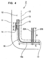
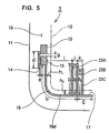
- FIG. 4 and 5 illustrating respectively a first and a second alteration of the window glass antenna system 1 according to the present invention.
- like reference numerals are used for corresponding parts of the window glass antenna 1 shown in Fig. 1 and their description will be omitted.
- a window glass antenna system 2 is disposed at a lower left corner of an automobile window glass 10 and comprised of a grounding electrode 13, a feeding electrode 15, two radiation patterns 22A, 22B, impedance adjusting element 14, 17, and a signal retrieval pattern 16.
- a window glass antenna system 3 which is disposed on a lower left corner of an automobile window glass 10. It comprises a grounding electrode 13, a feeding electrode 15, three radiation patterns 23A, 23B, 23C, impedance adjusting elements 14, 17, and a signal retrieval pattern 16.
- First two of the radiation patterns 23A, 23B have lengths al, a2 while the third one 23C has a length a3 slightly shorter than the lengths al, a2.
- Table 2 below and Fig. 6 illustrate the reception sensitivity characteristics of the window glass antenna system 3 of Fig. 5. These characteristics have been obtained by measuring with the antenna system 3 disposed on a lower left corner of the window glass 10 and having a grounding electrode 13 and a feeding electrode 15, both being 12 mm wide and 17 mm long, which are connected to a 2.5D-2V coaxial cable 19 (characteristic impedance 50 ⁇ ) of 1.5 m long.
- width of the impedance adjusting element 14 3mm
- Table 2 is a listing of values indicative of the reception sensitivity characteristics (3) of the window glass antenna system 3 as compared to those (60) of the conventional window glass antenna system 60 disclosed in Japanese Patent Laid-Open Publication No. 6-237109.
- Fig. 6 is a graphical representation of the reception sensitivity characteristics (3) and (60) of the window glass antenna system 3 and conventional antenna system 60, wherein the frequencies are shown along a transverse axis and the reception sensitivity is shown along a vertical axis.
- the window glass antenna system 3 exhibits the reception sensitivity higher by about 1.7 dB on an average than the conventional window glass antenna system 60. It will also be appreciated that the window glass antenna system 3 achieves the reception sensitivity of more than -3.6 dB over the entire bandwidth of 810 MHz - 960 MHz while keeping the reception sensitivity deviation to less than 1.0 dB and thus provides good characteristics.
- window glass antenna system 3 With the window glass antenna system 3 arranged as explained above, it becomes possible to provide increased reception sensitivity and to keep a reception sensitivity deviation in a used frequency bandwidth to a minimum.
Landscapes
- Details Of Aerials (AREA)
Abstract
Description
| RECEPTION SENSITIVITY CHARACTERISTICS OF WINDOW GLASS ANTENNA | ||
| 0 dB : reference dipole antenna | ||
| frequencies (MHz) | present window glass antenna system (1) | conv. window glass antenna system (60) |
| 810 | -4.4 | -6.7 |
| 820 | -4.0 | -5.8 |
| 830 | -3.4 | -4.5 |
| 840 | -2.7 | -3.8 |
| 850 | -3.1 | -3.8 |
| 860 | -2.8 | -3.6 |
| 870 | -2.8 | -3.9 |
| 880 | -2.8 | -3.6 |
| 890 | -2.9 | -3.5 |
| 900 | -2.3 | -3.4 |
| 910 | -2.6 | -3.9 |
| 920 | -2.7 | -4.0 |
| 930 | -2.7 | -3.9 |
| 940 | -2.7 | -5.2 |
| 950 | -4.0 | -6.4 |
| 960 | -4.8 | -9.2 |
| averages | -3.2 | -4.7 |
| RECEPTION SENSITIVITY CHARACTERISTICS OF WINDOW | ||
| 0 dB : reference dipole antenna | ||
| frequencies (MHz) | conv. window glass antenna system (60) | present window glass antenna system (3) |
| 810 | -6.7 | -3.6 |
| 820 | -5.8 | -3.2 |
| 830 | -4.5 | -2.9 |
| 840 | -3.8 | -3.1 |
| 850 | -3.8 | -2.6 |
| 860 | -3.6 | -2.9 |
| 870 | -3.9 | -3.3 |
| 880 | -3.6 | -3.1 |
| 890 | -3.5 | -3.2 |
| 900 | -3.4 | -2.9 |
| 910 | -3.9 | -2.9 |
| 920 | -4.0 | -2.8 |
| 930 | -3.9 | -2.6 |
| 940 | -5.2 | -2.9 |
| 950 | -6.4 | -3.1 |
| 960 | -9.2 | -3.0 |
| averages | -4.7 | -3.0 |
Claims (3)
- A window glass antenna system (1) comprising:a ground electrode (13) disposed on a surface of a side edge portion of a window glass (10) and connected with a braided outer conductor (20) of a coaxial cable (19);a feed electrode (15) disposed on said surface of said window glass side edge portion adjacent to said ground electrode and connected with a center conductor (21) of said coaxial cable (19);a signal retrieval pattern (16) comprising a first portion having one end connected to said feed electrode (15) and extending downwardly along said window glass side edge, and a second portion (16a) connected to the other end of said first portion and extending horizontally; and a radiation pattern (18) connected to said second portion (16a) and extending substantially perpendicularly thereto.
- The window glass antenna system (1) of claim 1, further comprising a first impedance adjusting element (14) extending from said grounding electrode (13), and a second impedance adjusting element (17) comprising a continuation of said horizontal portion (16a) of said signal retrieval pattern (16).
- The window glass antenna system (1; 2; 3) of claim 1, wherein said radiation pattern (18) comprises a plurality of radiation patterns (22a, 22b, 23a, 23b, 23c) connected substantially perpendicularly to said horizontal portion (16a) of said signal retrieval pattern (16).
Applications Claiming Priority (3)
| Application Number | Priority Date | Filing Date | Title |
|---|---|---|---|
| JP65207/97 | 1997-03-18 | ||
| JP6520797 | 1997-03-18 | ||
| JP9065207A JPH10261911A (en) | 1997-03-18 | 1997-03-18 | Window glass antenna |
Publications (3)
| Publication Number | Publication Date |
|---|---|
| EP0866515A2 true EP0866515A2 (en) | 1998-09-23 |
| EP0866515A3 EP0866515A3 (en) | 1998-12-30 |
| EP0866515B1 EP0866515B1 (en) | 2004-06-16 |
Family
ID=13280250
Family Applications (1)
| Application Number | Title | Priority Date | Filing Date |
|---|---|---|---|
| EP98301327A Expired - Lifetime EP0866515B1 (en) | 1997-03-18 | 1998-02-24 | Window glass antenna system |
Country Status (5)
| Country | Link |
|---|---|
| US (1) | US6028557A (en) |
| EP (1) | EP0866515B1 (en) |
| JP (1) | JPH10261911A (en) |
| AU (1) | AU728002B2 (en) |
| DE (1) | DE69824466T2 (en) |
Cited By (2)
| Publication number | Priority date | Publication date | Assignee | Title |
|---|---|---|---|---|
| WO2005027260A2 (en) * | 2003-09-15 | 2005-03-24 | Harada Industry Co., Ltd. | Integrated antenna with coupled ground |
| EP3125361A1 (en) * | 2015-07-31 | 2017-02-01 | AGC Automotive Americas R & D, Inc. | Multi-band antenna for a window assembly |
Families Citing this family (13)
| Publication number | Priority date | Publication date | Assignee | Title |
|---|---|---|---|---|
| US6118410A (en) * | 1999-07-29 | 2000-09-12 | General Motors Corporation | Automobile roof antenna shelf |
| US6441791B1 (en) * | 2000-08-21 | 2002-08-27 | Nippon Sheet Glass Co., Ltd. | Glass antenna system for mobile communication |
| US6346917B1 (en) * | 2000-11-09 | 2002-02-12 | Receptec Llc | Method for implementing a vehicular antenna system |
| US7149118B2 (en) * | 2002-09-16 | 2006-12-12 | Impinj, Inc. | Method and apparatus for programming single-poly pFET-based nonvolatile memory cells |
| WO2004084343A1 (en) * | 2003-03-19 | 2004-09-30 | Central Glass Co., Ltd. | Antenna for vehicle |
| US7154444B2 (en) * | 2003-04-04 | 2006-12-26 | General Motors Corporation | Ground plane compensation for mobile antennas |
| JPWO2005069439A1 (en) * | 2004-01-14 | 2007-09-06 | 株式会社ヨコオ | Multiband antenna and portable communication device |
| US7446719B2 (en) * | 2004-05-28 | 2008-11-04 | Denso Corporation | Mobile antenna mounted on a vehicle body |
| KR101269252B1 (en) * | 2004-07-21 | 2013-05-29 | 아사히 가라스 가부시키가이샤 | A high frequency glass antenna for an automobile |
| US8274357B2 (en) * | 2006-05-08 | 2012-09-25 | Powertech Industrial Co., Ltd. | Varistor having ceramic case |
| JP4634474B2 (en) * | 2008-03-03 | 2011-02-16 | 原田工業株式会社 | Antenna device for vehicle window |
| DE102008022711A1 (en) * | 2008-05-07 | 2009-11-26 | Ses Rfid Solutions Gmbh | Spatial structure with a transponder and method for generating the same |
| JP5141503B2 (en) * | 2008-11-07 | 2013-02-13 | 旭硝子株式会社 | Glass antenna for vehicle and window glass for vehicle |
Citations (5)
| Publication number | Priority date | Publication date | Assignee | Title |
|---|---|---|---|---|
| GB2216341A (en) * | 1988-02-25 | 1989-10-04 | Central Glass Co Ltd | Vehicle window glass antenna |
| EP0557794A1 (en) * | 1992-02-26 | 1993-09-01 | Flachglas Aktiengesellschaft | Glass antenna mounted into the window cutout of a metallic motorcar body |
| US5264858A (en) * | 1990-07-31 | 1993-11-23 | Asahi Glass Company Ltd. | Glass antenna for a telephone of an automobile |
| JPH06237109A (en) * | 1993-02-09 | 1994-08-23 | Nippon Sheet Glass Co Ltd | Glass antenna for automobile telephone system |
| JPH08162827A (en) * | 1994-12-05 | 1996-06-21 | Nippon Sheet Glass Co Ltd | Glass antenna system for automobile telephone system |
Family Cites Families (5)
| Publication number | Priority date | Publication date | Assignee | Title |
|---|---|---|---|---|
| JPH04132401A (en) * | 1990-09-25 | 1992-05-06 | Central Glass Co Ltd | Glass antenna for vehicle |
| JP3061457B2 (en) * | 1991-09-20 | 2000-07-10 | 東芝電池株式会社 | Organic electrolyte battery |
| US5521606A (en) * | 1992-02-05 | 1996-05-28 | Nippon Sheet Glass Co., Ltd. | Window glass antenna for motor vehicles |
| US5657029A (en) * | 1993-02-09 | 1997-08-12 | Nippon Sheet Glass Co., Ltd. | Glass antenna device for automobile telephone |
| US5499034A (en) * | 1993-04-30 | 1996-03-12 | Central Glass Company, Limited | Glass antenna for automotive vehicles |
-
1997
- 1997-03-18 JP JP9065207A patent/JPH10261911A/en active Pending
-
1998
- 1998-02-24 DE DE69824466T patent/DE69824466T2/en not_active Expired - Fee Related
- 1998-02-24 EP EP98301327A patent/EP0866515B1/en not_active Expired - Lifetime
- 1998-03-12 US US09/041,551 patent/US6028557A/en not_active Expired - Fee Related
- 1998-03-18 AU AU59373/98A patent/AU728002B2/en not_active Ceased
Patent Citations (5)
| Publication number | Priority date | Publication date | Assignee | Title |
|---|---|---|---|---|
| GB2216341A (en) * | 1988-02-25 | 1989-10-04 | Central Glass Co Ltd | Vehicle window glass antenna |
| US5264858A (en) * | 1990-07-31 | 1993-11-23 | Asahi Glass Company Ltd. | Glass antenna for a telephone of an automobile |
| EP0557794A1 (en) * | 1992-02-26 | 1993-09-01 | Flachglas Aktiengesellschaft | Glass antenna mounted into the window cutout of a metallic motorcar body |
| JPH06237109A (en) * | 1993-02-09 | 1994-08-23 | Nippon Sheet Glass Co Ltd | Glass antenna for automobile telephone system |
| JPH08162827A (en) * | 1994-12-05 | 1996-06-21 | Nippon Sheet Glass Co Ltd | Glass antenna system for automobile telephone system |
Non-Patent Citations (2)
| Title |
|---|
| PATENT ABSTRACTS OF JAPAN vol. 18, no. 623 (E-1635), 28 November 1994 & JP 06 237109 A (NIPPON SHEET GLASS CO. LTD.), 23 August 1994 * |
| PATENT ABSTRACTS OF JAPAN vol. 96, no. 10, 31 October 1996 & JP 08 162827 A (NIPPON SHEET GLASS CO. LTD.), 21 June 1996 * |
Cited By (6)
| Publication number | Priority date | Publication date | Assignee | Title |
|---|---|---|---|---|
| WO2005027260A2 (en) * | 2003-09-15 | 2005-03-24 | Harada Industry Co., Ltd. | Integrated antenna with coupled ground |
| WO2005027260A3 (en) * | 2003-09-15 | 2005-06-02 | Harada Ind Co Ltd | Integrated antenna with coupled ground |
| GB2422962A (en) * | 2003-09-15 | 2006-08-09 | Harada Ind Co Ltd | Integrated antenna with coupled ground |
| GB2422962B (en) * | 2003-09-15 | 2007-09-19 | Harada Ind Co Ltd | Integrated antenna with coupled ground |
| EP3125361A1 (en) * | 2015-07-31 | 2017-02-01 | AGC Automotive Americas R & D, Inc. | Multi-band antenna for a window assembly |
| US10243251B2 (en) | 2015-07-31 | 2019-03-26 | Agc Automotive Americas R&D, Inc. | Multi-band antenna for a window assembly |
Also Published As
| Publication number | Publication date |
|---|---|
| DE69824466T2 (en) | 2005-06-30 |
| AU728002B2 (en) | 2001-01-04 |
| DE69824466D1 (en) | 2004-07-22 |
| US6028557A (en) | 2000-02-22 |
| EP0866515A3 (en) | 1998-12-30 |
| JPH10261911A (en) | 1998-09-29 |
| AU5937398A (en) | 1998-09-24 |
| EP0866515B1 (en) | 2004-06-16 |
Similar Documents
| Publication | Publication Date | Title |
|---|---|---|
| US5754145A (en) | Printed antenna | |
| US5198826A (en) | Wide-band loop antenna with outer and inner loop conductors | |
| EP0655797B1 (en) | Quarter-wave gap-coupled tunable strip antenna | |
| EP0866515B1 (en) | Window glass antenna system | |
| US6822613B2 (en) | High frequency wave glass antenna for an automobile | |
| US5418543A (en) | Antenna for vehicle window | |
| JP2003505963A (en) | Capacitively tuned broadband antenna structure | |
| JPS6259922B2 (en) | ||
| EP1459410B1 (en) | High-bandwidth multi-band antenna | |
| US6937198B2 (en) | Glass antenna system for vehicles | |
| US7071886B2 (en) | Glass antenna and glass antenna system for vehicles | |
| JP2824790B2 (en) | Two-wire loop antenna | |
| JPH08213820A (en) | Glass antenna system for mobile telephone set | |
| EP0335708B1 (en) | A vehicle window antenna | |
| EP0618637A1 (en) | Antenna structure | |
| EP0646985B1 (en) | Tuned stripline antenna with a sail | |
| EP0487053A1 (en) | Improved antenna structure | |
| EP1079460A2 (en) | Glass antenna device | |
| JPH03114303A (en) | Broad band loop antenna | |
| JP2023051789A (en) | vehicle window glass | |
| JP2021175045A (en) | Window glass for vehicle | |
| GB1561742A (en) | Multiband antenna for window panes | |
| JPH09321518A (en) | Glass antenna for mobile telephone | |
| JPH07162218A (en) | Windowpane antenna for automobile | |
| JPH07122918A (en) | Glass antenna for vehicle |
Legal Events
| Date | Code | Title | Description |
|---|---|---|---|
| PUAI | Public reference made under article 153(3) epc to a published international application that has entered the european phase |
Free format text: ORIGINAL CODE: 0009012 |
|
| AK | Designated contracting states |
Kind code of ref document: A2 Designated state(s): DE FR GB |
|
| AX | Request for extension of the european patent |
Free format text: AL;LT;LV;MK;RO;SI |
|
| PUAL | Search report despatched |
Free format text: ORIGINAL CODE: 0009013 |
|
| AK | Designated contracting states |
Kind code of ref document: A3 Designated state(s): AT BE CH DE DK ES FI FR GB GR IE IT LI LU MC NL PT SE |
|
| AX | Request for extension of the european patent |
Free format text: AL;LT;LV;MK;RO;SI |
|
| 17P | Request for examination filed |
Effective date: 19990419 |
|
| AKX | Designation fees paid |
Free format text: DE FR GB |
|
| 17Q | First examination report despatched |
Effective date: 20030710 |
|
| GRAP | Despatch of communication of intention to grant a patent |
Free format text: ORIGINAL CODE: EPIDOSNIGR1 |
|
| GRAS | Grant fee paid |
Free format text: ORIGINAL CODE: EPIDOSNIGR3 |
|
| GRAA | (expected) grant |
Free format text: ORIGINAL CODE: 0009210 |
|
| AK | Designated contracting states |
Kind code of ref document: B1 Designated state(s): DE FR GB |
|
| REG | Reference to a national code |
Ref country code: GB Ref legal event code: FG4D |
|
| REF | Corresponds to: |
Ref document number: 69824466 Country of ref document: DE Date of ref document: 20040722 Kind code of ref document: P |
|
| ET | Fr: translation filed | ||
| PG25 | Lapsed in a contracting state [announced via postgrant information from national office to epo] |
Ref country code: GB Free format text: LAPSE BECAUSE OF NON-PAYMENT OF DUE FEES Effective date: 20050224 |
|
| PLBE | No opposition filed within time limit |
Free format text: ORIGINAL CODE: 0009261 |
|
| STAA | Information on the status of an ep patent application or granted ep patent |
Free format text: STATUS: NO OPPOSITION FILED WITHIN TIME LIMIT |
|
| 26N | No opposition filed |
Effective date: 20050317 |
|
| GBPC | Gb: european patent ceased through non-payment of renewal fee |
Effective date: 20050223 |
|
| PGFP | Annual fee paid to national office [announced via postgrant information from national office to epo] |
Ref country code: DE Payment date: 20080221 Year of fee payment: 11 |
|
| PGFP | Annual fee paid to national office [announced via postgrant information from national office to epo] |
Ref country code: FR Payment date: 20080208 Year of fee payment: 11 |
|
| REG | Reference to a national code |
Ref country code: FR Ref legal event code: ST Effective date: 20091030 |
|
| PG25 | Lapsed in a contracting state [announced via postgrant information from national office to epo] |
Ref country code: DE Free format text: LAPSE BECAUSE OF NON-PAYMENT OF DUE FEES Effective date: 20090901 |
|
| PG25 | Lapsed in a contracting state [announced via postgrant information from national office to epo] |
Ref country code: FR Free format text: LAPSE BECAUSE OF NON-PAYMENT OF DUE FEES Effective date: 20090302 |