EP0861734A1 - Printer for printing a plurality of images on a substrate web - Google Patents
Printer for printing a plurality of images on a substrate web Download PDFInfo
- Publication number
- EP0861734A1 EP0861734A1 EP97301251A EP97301251A EP0861734A1 EP 0861734 A1 EP0861734 A1 EP 0861734A1 EP 97301251 A EP97301251 A EP 97301251A EP 97301251 A EP97301251 A EP 97301251A EP 0861734 A1 EP0861734 A1 EP 0861734A1
- Authority
- EP
- European Patent Office
- Prior art keywords
- printing
- web
- synchronisation
- marks
- substrate web
- Prior art date
- Legal status (The legal status is an assumption and is not a legal conclusion. Google has not performed a legal analysis and makes no representation as to the accuracy of the status listed.)
- Withdrawn
Links
Images

Classifications
-
- B—PERFORMING OPERATIONS; TRANSPORTING
- B41—PRINTING; LINING MACHINES; TYPEWRITERS; STAMPS
- B41J—TYPEWRITERS; SELECTIVE PRINTING MECHANISMS, i.e. MECHANISMS PRINTING OTHERWISE THAN FROM A FORME; CORRECTION OF TYPOGRAPHICAL ERRORS
- B41J3/00—Typewriters or selective printing or marking mechanisms characterised by the purpose for which they are constructed
- B41J3/54—Typewriters or selective printing or marking mechanisms characterised by the purpose for which they are constructed with two or more sets of type or printing elements
-
- B—PERFORMING OPERATIONS; TRANSPORTING
- B41—PRINTING; LINING MACHINES; TYPEWRITERS; STAMPS
- B41F—PRINTING MACHINES OR PRESSES
- B41F13/00—Common details of rotary presses or machines
- B41F13/02—Conveying or guiding webs through presses or machines
- B41F13/025—Registering devices
Definitions
- This invention relates to a printer for printing a plurality of images on a substrate web.
- the printer described by Rodek operates on the basis of the substrate web moving at a nominally constant speed and of the provision of uniformly spaced marks on the web.
- the requirements may be difficult to meet accurately. Variations in operating conditions or in the condition of the web, may result in minor variations in the web speed.
- the substrate web has been pre-printed, it is rolled and stored prior to use, during which some dimensional changes in the web, such as stretching and relaxing, may occur. The result of this is that marks pre-printed on the web may no longer be equally spaced.
- the printer described by Rodek also has the disadvantage that, should any change in web speed be made, a correction in the timing of the exposure is made at a point which may be located in the middle of an image. An image carrying such a intermediate correction is undesirable.
- the printer includes a digital printing station and a printing sequence is initiated at the printing station in response to the sensing of each of a plurality of synchronisation marks.
- a printer for printing a plurality of images on a substrate web carrying a plurality of synchronisation marks comprising:
- a method for printing a plurality of images on a substrate web carrying a plurality of synchronisation marks comprising:
- the printer will usually further comprise means such as an encoder for generating signals indicative of web displacement, the control means being adapted to act in response to such web displacement signals.
- the control device operates independently of the web speed, and is in particular insensitive to variations in the web speed.
- the printer may further comprise a cutting device positioned downstream of the printing station, for cutting the web into sheets, each cut sheet carrying an image and its associated synchronisation mark.
- the cutting device is controlled by the control device to cut the web at a predetermined location relative to an associated one of the synchronisation marks.
- the sensing device is preferably sensitive to pre-printed synchronisation marks on the substrate web, watermarks in the substrate web, and/or disconformities in the substrate web.
- the sensing device is sensitive to pre-printed synchronisation marks distinguishable in the visible spectrum.
- the preferred longitudinal dimension (direction of web movement) of each synchronisation mark depends upon the expected web speed, and is, for example, at least 0.6 mm, typically from 1.00 mm to 4.00 mm, at a web speed of about 120 mm/sec.
- a lateral dimension of at least 10 mm should be sufficient to allow for variations in cross-web alignment.
- the spacing between consecutive marks should be at least 0.6 mm.
- the synchronisation mark may be located in a margin, i.e. to one side of the image to be printed, between adjacent pages, within the area to be occupied by the image, or even as part of the image. The latter will more usually be the case when the synchronisation mark is a watermark or a disconformity in the substrate web.
- a reflective optical sensor is suitable for detecting synchronisation marks in the form of printed marks or punched holes, whereas a transmissive optical sensor is suitable for detecting watermarks, security items within the substrate web or die-cuts.
- a non-optical sensor can be used to detect non-conformities in the substrate web.
- the sensor may be adapted to distinguish the synchronisation marks from other marks on the substrate web.
- the sensor may be an intelligent sensor capable of recognising synchronisation marks of a predetermined shape and distinguishing these from other marks which may occur on the web. This is important where the substrate web is pre-printed, for example with a form layout, and the synchronisation mark is to be located other than in a otherwise empty margin.
- the intelligence may be incorporated in the sensor itself, or in the control device.
- the images may be variable images to be printed in a predetermined sequence, the printing of each image at the printing station being initiated by the sensing of an associated synchronisation mark on the substrate web.
- the printing of each image at the printing station is initiated only by the sensing of an associated synchronisation mark on the substrate web, whereby failure to sense an expected synchronisation mark on the substrate web results in failure to initiate the printing of an image at the printing station.
- failure to sense an expected synchronisation mark on the substrate web may result in the initiation of the printing of an image at said printing station, albeit based on an extrapolated position calculated from the position of earlier sensed synchronisation marks and their running average inter-distance.
- One or more further printing stations may be provided, the feed means feeding the substrate web past each printing station in turn, enabling multi-colour images to printed on the web substrate.
- register control means may be provided for initiating a printing sequence at each printing station other than the first, in response to the start of printing at the first printing station, making use of web-displacement measurement, thereby enabling multi-colour images to be printed in register with each other.
- the method according to the invention may be used for the printing of identity documents, wherein the web substrate carries watermarks or security marks such as finely detailed images in at least one colour, and the printed images comprise variable data such as alpha-numeric data and multi-colour pictorial images.
- Other product examples include form printing, the printing of pre-die cut labels, flyers and direct mail documents carrying glued areas or perfume strips.
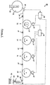
- the printer 10 comprises a plurality of digital printing stations 12, 14, 16, 18.
- Each printing station comprises a rotatable drum having photosensitive surface, an exposure device for image-wise exposing the photosensitive surface, a development unit to form a toner image, a transfer device for transferring the toner image to the substrate web, a cleaning device for removing excess toner form the photosensitive surface and a charging device for preparing the photosensitive surface for further exposure.
- Such a construction of the printing stations is conventional and is, for example, as described in United States patent No. US 5499093 (Aerens et al. assigned to Xeikon NV), and is not therefore shown in detail.
- the exposure devices are however indicated at 13, 15, 17, 19. It will be appreciated that the timing of the operation of an exposure device determines the timing of image printing at that printing station, as described in US 5499093.
- the web 24 carries a plurality of synchronisation marks (see Figure 2).
- a pair of co-operating drive rollers 28 feed the substrate web 24 past each printing station in turn, enabling multi-colour images to printed on the substrate web 24.
- a brake (not shown) acting on the roll 22, ensures that the web is under tension as it passes the printing stations.
- the substrate path through the printer is defined by a number of guide rollers 29.
- a sensing device 32 is positioned upstream of the first printing station 12 for sensing the synchronisation marks 26 on the web 24.
- the nature of the sensing device 32 is determined according to the nature of the synchronisation marks on the substrate web.
- a suitable sensing device is a reflective optical sensing device such as the KEYENCE FU-35FA sensor, with an F-2HA lens and an FS2-65 amplifier.
- a control device 38 for example in the form of a microprocessor, is provided for initiating a printing sequence at the first printing station 12 in response to the sensing of each of the synchronisation marks.
- the images are, for example, variable images to be printed in a predetermined sequence, the printing of each image at the first printing station 12 being initiated by the sensing of an associated synchronisation mark 26 on the substrate web 24.
- an encoder device 37 associated for example with the first printing station 12, is provided to provide output signals to the control device 38 indicative of web displacement.
- the control device 38 also includes means to determine that a synchronisation mark is missing from within a pre-selectable range wherein normally a mark is to be expected. Where such a mark is missing, a printing sequence is optionally initiated, albeit based on an extrapolated position calculated from the position of earlier marks and their running average inter-distance. Thus any irregularity in the pre-printing of the substrate web 24 is overcome.
- the printer shown in Figure 1 operates as follows. As the substrate web 24 is drawn off the roll 22, a synchronisation mark thereon eventually passes the sensor 32 and is detected thereby.
- the control device 38 receives a signal from the sensor 32 that a synchronisation mark has been detected. After a given distance of web travel, the control device sends a signal to the exposure device 13 of the first printing station 12, to initiate a printing sequence.
- the given distance of web travel between receiving the signal from the sensor 32 and initiating the printing sequence at printing station 12 is pre-calibrated to take account of:
- the control device 38 initiates a second printing sequence, and so on.
- the spacing of the synchronisation marks on the web 24 and the lengths of the images to be printed at the printing station 12, need not be regular, since each image is associated with a specific synchronisation mark. In this manner a plurality of images are printed on the web 24, each at a predetermined location relative to an associated one of the synchronisation marks 26.
- the further printing stations 14, 16 and 18 enable multi-colour images to be printed.
- Register control means 30 are provided for initiating a printing sequence at each of these further printing stations, in response to the start of printing at the first printing station 12, making use of web displacement measurements thereby enabling multi-colour images to be printed in register with each other. If no printing sequence is initiated at the first printing station 12, no images are printed by the further printing stations 14, 16, 18.
- the web After passing the last printing station 18, the web passes a toner image fixing station 39 where the images are rendered permanent on the substrate web 24.
- the web then passes to a cutting device 40 for cutting the web 24 into sheets 42, each cut sheet carrying an image and its associated synchronisation mark.
- the cutting device is controlled by the control device 38 to cut the web at a predetermined location relative to an associated one of the synchronisation marks 26.
- the printer 10 may be used for the printing of identity documents, wherein the substrate web 24 carries security data for example in monochrome, and the printed images comprise variable multi-colour pictorial images.
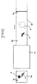
- the synchronisation marks on the substrate web 24 may take the form of pre-printed synchronisation marks 26 distinguishable in the visible spectrum, watermarks 34 formed in the substrate web, or disconformities such as metal strips 36 incorporated in the substrate web 24.
- Figure 2 shows, as an example, a portion of substrate web 24 approaching the printer 10.
- the substrate web is pre-printed with an image shown diagrammatically at 44. In the case of printing identity cards for example, this may be made up of finely detailed images or alpha-numeric data.
- the substrate passes through the printer 10, where a multi-colour further image shown diagrammatically at 46 is printed, and the web is cut into a sheet 42 of desired length.
- the newly printed image 46 may be for example a pictorial image of the person to whom the identity card is to apply.
- the image 46 has been printed at a predetermined location relative to the pre-printed image 44.
- the printed sheet 42 thus carries both images 44, 46 and the synchronisation mark 26.
- the synchronisation mark 26 lies in a margin to the image area. This has the advantage that, if desired, such synchronisation marks may be removed by subsequently trimming the sheet.
- Printed sheets carrying watermarks 34 or metal strips 36 will usually retain these features within the image area. This can be desirable for security reasons.
- the printer according to the invention may be adapted for duplex printing (i.e. printing on both faces of the substrate web), for example by the provision of further printing stations located on the opposite side of the web, such as in replacement for the guide rollers 29.
- the senor may be an intelligent sensor capable of recognising synchronisation marks of a predetermined shape and distinguishing these from other marks which may occur on the web.
- the web 24 carries synchronisation marks 26 which lie within the image area, which area also includes a pre-printed image 44, or may be part of the image.
- the sensor is able to distinguish the synchronisation marks from the image 44, by being programmed to apply the following criteria. Firstly, the synchronisation marks 26 must have a length in the web travelling direction falling within a configurable range. Secondly, the optical density of the synchronisation marks 26 must fall within a predetermined range relative to the unprinted substrate. The synchronisation marks 26 must be preceded and followed by blank areas 48, 49 of a configurable length. Furthermore, the sensor may be programmed to ignore any marks occurring on the web within a predetermined length range following a detected synchronisation mark. By application of these criteria, the synchronisation marks 26 may be distinguished from pre-printed images 44.
- a number of synchronisation marks of different configurations may be used in combination, the sensor intelligence being adapted to detect the sequence of such marks.
Abstract
The printer comprises:
- a digital printing station (12);
- a support (20) for a roll (22) of the substrate web (24) carrying a plurality of synchronisation marks;
- means (28) for feeding the substrate web (24) from the roll (22) past the printing station (12);
- a sensing device (32) positioned upstream of the printing station (12) for sensing the synchronisation marks on the web (24); and
- control means (38) for initiating a printing sequence at the printing station (12) in response to the sensing of each of the synchronisation marks (26, 34, 36). Thereby a plurality of images are printed on the web (24), each at a predetermined location relative to an associated one of the synchronisation marks (26, 34, 36).
Description
This invention relates to a printer for printing a
plurality of images on a substrate web.
It is known to print images, especially variable
images, on pre-printed stock. For example, United
States patent US 3858777 (Rodek / Xerox Corporation)
describes an apparatus for printing prerecorded
information on a pre-printed web. The image carried on
the pre-printed web may be, for example business forms,
it being necessary to print the variable data in
registration with the layout of the forms. The web
carries uniformly spaced marks which are detected by a
sensor as the web is unwound from a roll. By detection
of the marks, the displacement of the web can be
determined. Variable information to be printed on the
web, is carried on a film strip. The speed of the film
strip through an exposure device can be adjusted to
match the determined speed of the web.
The printer described by Rodek operates on the basis of
the substrate web moving at a nominally constant speed
and of the provision of uniformly spaced marks on the
web. In practice, the requirements may be difficult to
meet accurately. Variations in operating conditions or
in the condition of the web, may result in minor
variations in the web speed. Furthermore, after the
substrate web has been pre-printed, it is rolled and
stored prior to use, during which some dimensional
changes in the web, such as stretching and relaxing,
may occur. The result of this is that marks pre-printed
on the web may no longer be equally spaced.
Furthermore, it may well be desirable to pre-print
images of different lengths, with the result that the
use of uniformly spaced marks on the web is no longer
appropriate. The printer described by Rodek also has
the disadvantage that, should any change in web speed
be made, a correction in the timing of the exposure is
made at a point which may be located in the middle of
an image. An image carrying such a intermediate
correction is undesirable.
It is an object of the present invention to provide a
printer for the printing of variable data on a pre-printed
substrate web in which these disadvantages can
be overcome. More particularly, it is an object of the
present invention to provide such a printer in which
any correction in the timing of the printing sequence
is made between images, and in response to the
detection of a single mark carried on the substrate
web, the mark being associated in terms of position
reference with the image to be printed.
We have discovered that these objectives, and other
useful advantages, may be obtained where the printer
includes a digital printing station and a printing
sequence is initiated at the printing station in
response to the sensing of each of a plurality of
synchronisation marks.
According to a first aspect of the invention there is
provided a printer for printing a plurality of images
on a substrate web carrying a plurality of
synchronisation marks, the printer comprising:
- a digital printing station;
- a support for a roll of the substrate web;
- means for feeding the substrate web from the roll past the printing station;
- a sensing device positioned upstream of the printing station for sensing the synchronisation marks on the web; and
- control means for initiating a printing sequence at the printing station in response to the sensing of each of the synchronisation marks, whereby a plurality of images are printed on the web, each at a predetermined location relative to an associated one of the synchronisation marks.
According to a second aspect of the invention, there is
provided a method for printing a plurality of images on
a substrate web carrying a plurality of synchronisation
marks, the method comprising:
- feeding the substrate web from a roll past a printing station;
- sensing the synchronisation marks on the web device at a position upstream of the printing station; and
- initiating a printing sequence at the printing station in response to the sensing of each of the synchronisation marks, whereby a plurality of images are printed on the web, each at a predetermined location relative to an associated one of the synchronisation marks.
The printer will usually further comprise means such as
an encoder for generating signals indicative of web
displacement, the control means being adapted to act in
response to such web displacement signals. In this
manner, the control device operates independently of
the web speed, and is in particular insensitive to
variations in the web speed.
The printer may further comprise a cutting device
positioned downstream of the printing station, for
cutting the web into sheets, each cut sheet carrying an
image and its associated synchronisation mark. The
cutting device is controlled by the control device to
cut the web at a predetermined location relative to an
associated one of the synchronisation marks.
The sensing device is preferably sensitive to pre-printed
synchronisation marks on the substrate web,
watermarks in the substrate web, and/or disconformities
in the substrate web. For example, the sensing device
is sensitive to pre-printed synchronisation marks
distinguishable in the visible spectrum. The preferred
longitudinal dimension (direction of web movement) of
each synchronisation mark depends upon the expected web
speed, and is, for example, at least 0.6 mm, typically
from 1.00 mm to 4.00 mm, at a web speed of about 120
mm/sec. A lateral dimension of at least 10 mm should
be sufficient to allow for variations in cross-web
alignment. At a web speed of about 120 mm/sec, the
spacing between consecutive marks should be at least
0.6 mm. When a visible pre-printed mark is used, this
may be of any colour, but a yellow mark on a white
substrate is best avoided since it is more difficult to
detect with conventional sensors, than other colours.
The synchronisation mark may be located in a margin,
i.e. to one side of the image to be printed, between
adjacent pages, within the area to be occupied by the
image, or even as part of the image. The latter will
more usually be the case when the synchronisation mark
is a watermark or a disconformity in the substrate web.
A reflective optical sensor is suitable for detecting
synchronisation marks in the form of printed marks or
punched holes, whereas a transmissive optical sensor is
suitable for detecting watermarks, security items
within the substrate web or die-cuts. A non-optical
sensor can be used to detect non-conformities in the
substrate web.
The sensor may be adapted to distinguish the
synchronisation marks from other marks on the substrate
web. Thus the sensor may be an intelligent sensor
capable of recognising synchronisation marks of a
predetermined shape and distinguishing these from other
marks which may occur on the web. This is important
where the substrate web is pre-printed, for example
with a form layout, and the synchronisation mark is to
be located other than in a otherwise empty margin. The
intelligence may be incorporated in the sensor itself,
or in the control device.
The images may be variable images to be printed in a
predetermined sequence, the printing of each image at
the printing station being initiated by the sensing of
an associated synchronisation mark on the substrate
web. Ideally, the printing of each image at the
printing station is initiated only by the sensing of an
associated synchronisation mark on the substrate web,
whereby failure to sense an expected synchronisation
mark on the substrate web results in failure to
initiate the printing of an image at the printing
station. Alternatively, failure to sense an expected
synchronisation mark on the substrate web may result in
the initiation of the printing of an image at said
printing station, albeit based on an extrapolated
position calculated from the position of earlier sensed
synchronisation marks and their running average inter-distance.
One or more further printing stations may be provided,
the feed means feeding the substrate web past each
printing station in turn, enabling multi-colour images
to printed on the web substrate. In this embodiment,
register control means may be provided for initiating a
printing sequence at each printing station other than
the first, in response to the start of printing at the
first printing station, making use of web-displacement
measurement, thereby enabling multi-colour images to be
printed in register with each other.
The method according to the invention may be used for
the printing of identity documents, wherein the web
substrate carries watermarks or security marks such as
finely detailed images in at least one colour, and the
printed images comprise variable data such as alpha-numeric
data and multi-colour pictorial images. Other
product examples include form printing, the printing of
pre-die cut labels, flyers and direct mail documents
carrying glued areas or perfume strips.
The invention will now be described in further detail,
purely by way of example, with reference to the
accompanying drawings, in which:
As shown in Figure 1, the printer 10 comprises a
plurality of digital printing stations 12, 14, 16, 18.
Each printing station comprises a rotatable drum having
photosensitive surface, an exposure device for image-wise
exposing the photosensitive surface, a development
unit to form a toner image, a transfer device for
transferring the toner image to the substrate web, a
cleaning device for removing excess toner form the
photosensitive surface and a charging device for
preparing the photosensitive surface for further
exposure. Such a construction of the printing stations
is conventional and is, for example, as described in
United States patent No. US 5499093 (Aerens et al.
assigned to Xeikon NV), and is not therefore shown in
detail. The exposure devices are however indicated at
13, 15, 17, 19. It will be appreciated that the timing
of the operation of an exposure device determines the
timing of image printing at that printing station, as
described in US 5499093.
A support 20 for a roll 22 of a substrate web 24. The
web 24 carries a plurality of synchronisation marks
(see Figure 2). A pair of co-operating drive rollers
28 feed the substrate web 24 past each printing station
in turn, enabling multi-colour images to printed on the
substrate web 24. A brake (not shown) acting on the
roll 22, ensures that the web is under tension as it
passes the printing stations. The substrate path
through the printer is defined by a number of guide
rollers 29.
A sensing device 32 is positioned upstream of the first
printing station 12 for sensing the synchronisation
marks 26 on the web 24. The nature of the sensing
device 32 is determined according to the nature of the
synchronisation marks on the substrate web. A suitable
sensing device is a reflective optical sensing device
such as the KEYENCE FU-35FA sensor, with an F-2HA lens
and an FS2-65 amplifier.
A control device 38, for example in the form of a
microprocessor, is provided for initiating a printing
sequence at the first printing station 12 in response
to the sensing of each of the synchronisation marks.
The images are, for example, variable images to be
printed in a predetermined sequence, the printing of
each image at the first printing station 12 being
initiated by the sensing of an associated
synchronisation mark 26 on the substrate web 24.
Except in the case where the distance between the
sensor and the point of printing on the web is the same
as the distance between the exposure device and the
point of printing on the web, it is necessary to
provide means for generating signals indicative of web
displacement. In the illustrated embodiment, an
encoder device 37, associated for example with the
first printing station 12, is provided to provide
output signals to the control device 38 indicative of
web displacement.
Since the printing of each image at the first printing
station 12 is initiated only by the sensing of an
associated synchronisation mark on the substrate web
24, failure to sense an expected synchronisation mark
on the substrate web 24 results in failure to initiate
the printing of an image at the printing station. The
control device 38 also includes means to determine that
a synchronisation mark is missing from within a pre-selectable
range wherein normally a mark is to be
expected. Where such a mark is missing, a printing
sequence is optionally initiated, albeit based on an
extrapolated position calculated from the position of
earlier marks and their running average inter-distance.
Thus any irregularity in the pre-printing of the
substrate web 24 is overcome.
The printer shown in Figure 1 operates as follows. As
the substrate web 24 is drawn off the roll 22, a
synchronisation mark thereon eventually passes the
sensor 32 and is detected thereby. The control device
38 receives a signal from the sensor 32 that a
synchronisation mark has been detected. After a given
distance of web travel, the control device sends a
signal to the exposure device 13 of the first printing
station 12, to initiate a printing sequence. The given
distance of web travel between receiving the signal
from the sensor 32 and initiating the printing sequence
at printing station 12 is pre-calibrated to take
account of:
- the web path distance from the
sensor 32 to thefirst printing station 12; - the distance travelled by the web after the
initiation of the printing sequence before the
first printing station 12 causes an image to be formed on theweb 24; and - the desired longitudinal displacement between the position of the synchronisation mark and the start of the image.
When a second synchronisation mark is detected by the
sensor 32, the control device 38 initiates a second
printing sequence, and so on. The spacing of the
synchronisation marks on the web 24 and the lengths of
the images to be printed at the printing station 12,
need not be regular, since each image is associated
with a specific synchronisation mark. In this manner a
plurality of images are printed on the web 24, each at
a predetermined location relative to an associated one
of the synchronisation marks 26.
The further printing stations 14, 16 and 18 enable
multi-colour images to be printed. Register control
means 30 are provided for initiating a printing
sequence at each of these further printing stations, in
response to the start of printing at the first printing
station 12, making use of web displacement measurements
thereby enabling multi-colour images to be printed in
register with each other. If no printing sequence is
initiated at the first printing station 12, no images
are printed by the further printing stations 14, 16,
18.
After passing the last printing station 18, the web
passes a toner image fixing station 39 where the images
are rendered permanent on the substrate web 24. The
web then passes to a cutting device 40 for cutting the
web 24 into sheets 42, each cut sheet carrying an image
and its associated synchronisation mark. The cutting
device is controlled by the control device 38 to cut
the web at a predetermined location relative to an
associated one of the synchronisation marks 26.
The printer 10 may be used for the printing of identity
documents, wherein the substrate web 24 carries
security data for example in monochrome, and the
printed images comprise variable multi-colour pictorial
images.
As shown in Figure 2, the synchronisation marks on the
substrate web 24 may take the form of pre-printed
synchronisation marks 26 distinguishable in the visible
spectrum, watermarks 34 formed in the substrate web, or
disconformities such as metal strips 36 incorporated in
the substrate web 24. Figure 2 shows, as an example, a
portion of substrate web 24 approaching the printer 10.
The substrate web is pre-printed with an image shown
diagrammatically at 44. In the case of printing
identity cards for example, this may be made up of
finely detailed images or alpha-numeric data. The
substrate passes through the printer 10, where a multi-colour
further image shown diagrammatically at 46 is
printed, and the web is cut into a sheet 42 of desired
length. The newly printed image 46 may be for example
a pictorial image of the person to whom the identity
card is to apply. The image 46 has been printed at a
predetermined location relative to the pre-printed
image 44. The printed sheet 42 thus carries both
images 44, 46 and the synchronisation mark 26. In the
illustrated example, the synchronisation mark 26 lies
in a margin to the image area. This has the advantage
that, if desired, such synchronisation marks may be
removed by subsequently trimming the sheet. Printed
sheets carrying watermarks 34 or metal strips 36, will
usually retain these features within the image area.
This can be desirable for security reasons.
The printer according to the invention may be adapted
for duplex printing (i.e. printing on both faces of the
substrate web), for example by the provision of further
printing stations located on the opposite side of the
web, such as in replacement for the guide rollers 29.
Referring to Figure 3, the sensor may be an intelligent
sensor capable of recognising synchronisation marks of
a predetermined shape and distinguishing these from
other marks which may occur on the web. In this case
the web 24 carries synchronisation marks 26 which lie
within the image area, which area also includes a pre-printed
image 44, or may be part of the image. The
sensor is able to distinguish the synchronisation marks
from the image 44, by being programmed to apply the
following criteria. Firstly, the synchronisation marks
26 must have a length in the web travelling direction
falling within a configurable range. Secondly, the
optical density of the synchronisation marks 26 must
fall within a predetermined range relative to the unprinted
substrate. The synchronisation marks 26 must
be preceded and followed by blank areas 48, 49 of a
configurable length. Furthermore, the sensor may be
programmed to ignore any marks occurring on the web
within a predetermined length range following a
detected synchronisation mark. By application of these
criteria, the synchronisation marks 26 may be
distinguished from pre-printed images 44.
A number of synchronisation marks of different
configurations may be used in combination, the sensor
intelligence being adapted to detect the sequence of
such marks.
Claims (20)
- A printer for printing a plurality of images on a substrate web (24) carrying a plurality of synchronisation marks (26, 34, 36), said printer comprising:a digital printing station (12);a support (20) for a roll (22) of said substrate web (24);means (28) for feeding said substrate web (24) from said roll (22) past said printing station (12);a sensing device (32) positioned upstream of said printing station (12) for sensing said synchronisation marks (26, 34, 36) on said web (24); andcontrol means (38) for initiating a printing sequence at said printing station (12) in response to the sensing of each of said synchronisation marks (26, 34, 36), whereby a plurality of images are printed on said web (24), each at a predetermined location relative to an associated one of said synchronisation marks (26, 34, 36).
- A printer according to claim 1, further comprising means (37) for generating signals indicative of web displacement, said control means (38) being adapted to act in response to said web displacement signals.
- A printer according to claim 1 or 2, wherein said sensing device (32) is sensitive to pre-printed synchronisation marks (26) on said substrate web (24), watermarks (34) in said substrate web (24), and/or disconformities (36) in said substrate web (24).
- A printer according to claim 3, wherein said sensing device (32) is sensitive to synchronisation marks (26) distinguishable in the visible spectrum.
- A printer according to any preceding claim, wherein said sensing device is adapted to distinguish said synchronisation marks from other marks on said substrate web.
- A printer according to any preceding claim, further comprising a cutting device (40) positioned downstream of said printing station (12), for cutting said web (24) into sheets (42), each cut sheet carrying an image and its associated synchronisation mark, said cutting device (40) being controlled by the control device (38) to cut said web at a predetermined location relative to an associated one of the synchronisation marks (26).
- A printer according to any preceding claim, wherein one or more further printing stations (14, 16, 18) are provided and said feed means (28) feeds said substrate web (24) past each further printing station (14, 16, 18) in turn, enabling multi-colour images to printed on said substrate web (24).
- A printer according to claim 7, further comprising register control means (30) for initiating a printing sequence at each further printing station (12, 14, 16, 18), said register control means (30) being responsive to the start of printing at the first printing station (12), thereby enabling multi-colour images to be printed in register with each other.
- A method for printing a plurality of images on a substrate web (24) carrying a plurality of synchronisation marks (26, 34, 36), said method comprising:feeding said substrate web (24) from a roll (22) past a printing station (12);sensing said synchronisation marks (26, 34, 36) on said web (24) at a position upstream of said printing station (12); andinitiating a printing sequence at said printing station (12) in response to the sensing of each of said synchronisation marks (26, 34, 36), whereby a plurality of images are printed on said web (24), each at a predetermined location relative to an associated one of said synchronisation marks (26, 34, 36).
- A method according to claim 9, further comprising generating signals indicative of web displacement and initiating a printing sequence at said printing station (12) in response to said web displacement signals.
- A method according to claim 9 or 10, wherein said synchronisation marks on said substrate web (24) are pre-printed synchronisation marks (26), watermarks (34), disconformities (36) in said substrate web (24), or any combination thereof.
- A method according to claim 11, wherein said synchronisation marks (26) are distinguishable in the visible spectrum.
- A method according to any one of claims 9 to 12, further comprising distinguishing said synchronisation marks from other marks on said substrate web.
- A method according to any one of claims 9 to 13, wherein said images are variable images to be printed in a predetermined sequence, the printing of each image at said printing station (12) being initiated by the sensing of an associated synchronisation mark on said substrate web (24).
- A method according to claim 14, wherein the printing of each image at said printing station (12) is initiated only by the sensing of an associated synchronisation mark (26, 34, 36) on said substrate web (24), whereby failure to sense an expected synchronisation mark (26, 34, 36) on said substrate web (24) results in failure to initiate the printing of an image at said printing station (12).
- A method according to claim 14, whereby failure to sense an expected synchronisation mark (26, 34, 36) on said substrate web (24) results in the initiation of the printing of an image at said printing station (12) based on an extrapolated position calculated from the position of earlier sensed synchronisation marks and their running average inter-distance.
- A method according to any one of claims 9 to 16, further comprising cutting said web (24) into sheets (42) at a position downstream of said printing station (12), each cut sheet carrying an image and its associated synchronisation mark, said cutting device (40) being controlled by the control device (38) to cut said web at a predetermined location relative to an associated one of the synchronisation marks (26).
- A method according to any one of claims 9 to 17, wherein one or more further printing stations (14, 16, 18) are provided and said substrate web (24) is fed past each printing station (14, 16, 18) in turn, enabling multi-colour images to printed on said substrate web (24).
- A method according to claim 18, wherein the start of printing at each further printing station (14, 16, 18) is adjusted in response to the start of printing at the first printing station (12), thereby enabling multi-colour images to be printed in register with each other.
- A method according to claim 18 or 19, for the printing of identity documents, wherein said substrate web (24) carries security images in at least one colour, and said printed images comprise variable alpha-numeric and/or multi-colour pictorial images.
Priority Applications (5)
| Application Number | Priority Date | Filing Date | Title |
|---|---|---|---|
| EP97301251A EP0861734A1 (en) | 1997-02-26 | 1997-02-26 | Printer for printing a plurality of images on a substrate web |
| US09/026,444 US5951182A (en) | 1997-02-26 | 1998-02-19 | Printer for printing images on a substrate web |
| DE69805362T DE69805362T2 (en) | 1997-02-26 | 1998-02-23 | Printer for printing a plurality of images on a web |
| EP19980301297 EP0878311B1 (en) | 1997-02-26 | 1998-02-23 | Printer for printing a plurality of images on a substrate web |
| JP10042717A JPH10264475A (en) | 1997-02-26 | 1998-02-25 | Printer and method for printing a plurality of images on basic material web |
Applications Claiming Priority (1)
| Application Number | Priority Date | Filing Date | Title |
|---|---|---|---|
| EP97301251A EP0861734A1 (en) | 1997-02-26 | 1997-02-26 | Printer for printing a plurality of images on a substrate web |
Publications (1)
| Publication Number | Publication Date |
|---|---|
| EP0861734A1 true EP0861734A1 (en) | 1998-09-02 |
Family
ID=8229229
Family Applications (1)
| Application Number | Title | Priority Date | Filing Date |
|---|---|---|---|
| EP97301251A Withdrawn EP0861734A1 (en) | 1997-02-26 | 1997-02-26 | Printer for printing a plurality of images on a substrate web |
Country Status (4)
| Country | Link |
|---|---|
| US (1) | US5951182A (en) |
| EP (1) | EP0861734A1 (en) |
| JP (1) | JPH10264475A (en) |
| DE (1) | DE69805362T2 (en) |
Cited By (3)
| Publication number | Priority date | Publication date | Assignee | Title |
|---|---|---|---|---|
| EP0995604A1 (en) * | 1998-10-20 | 2000-04-26 | Eastman Kodak Company | Ink jet printing registered color images |
| EP1197456A1 (en) * | 2000-10-10 | 2002-04-17 | Grapha-Holding AG | Method of and device for the production of printed products |
| WO2014202253A1 (en) * | 2013-06-17 | 2014-12-24 | Koenig & Bauer Aktiengesellschaft | Printing machine having a plurality of printing units, which jointly print on a printing material |
Families Citing this family (10)
| Publication number | Priority date | Publication date | Assignee | Title |
|---|---|---|---|---|
| DE59800807D1 (en) * | 1997-11-10 | 2001-07-05 | Oce Printing Systems Gmbh | METHOD AND DEVICE FOR TRANSPORTING A PRINTED, TRAIN-SHAPED RECORDING MEDIUM IN A PRINTING DEVICE |
| US6905269B2 (en) * | 2002-07-03 | 2005-06-14 | Oki Data Americas, Inc. | System and method for continuous label printing |
| US6952994B2 (en) * | 2003-10-27 | 2005-10-11 | Jpatton Sports Marketing | Identification devices and methods for producing the identification devices |
| US7857414B2 (en) * | 2008-11-20 | 2010-12-28 | Xerox Corporation | Printhead registration correction system and method for use with direct marking continuous web printers |
| JP5213893B2 (en) * | 2010-02-26 | 2013-06-19 | キヤノン株式会社 | Print control method and printing apparatus |
| JP4941577B2 (en) * | 2010-05-12 | 2012-05-30 | セイコーエプソン株式会社 | Inkjet printing method and inkjet printing apparatus |
| WO2012140661A1 (en) * | 2011-04-11 | 2012-10-18 | Navneet Kalia | Customized perfume sampler paper strips with user generated messages printed |
| JP6031799B2 (en) * | 2012-03-30 | 2016-11-24 | ブラザー工業株式会社 | Printing device |
| US9361550B2 (en) * | 2012-08-06 | 2016-06-07 | Tetra Laval Holdings & Finance S.A. | Processing webs using printed graphic code symbol relating to web features |
| JP6789687B2 (en) * | 2016-06-17 | 2020-11-25 | 株式会社日本マイクロニクス | Sheet-shaped device, sheet-shaped secondary battery manufacturing method, and manufacturing equipment |
Citations (5)
| Publication number | Priority date | Publication date | Assignee | Title |
|---|---|---|---|---|
| US3858777A (en) * | 1972-05-17 | 1975-01-07 | Xerox Corp | Printing apparatus including registration control |
| DE3420304A1 (en) * | 1983-05-31 | 1984-12-06 | Fraver S.A., Luxemburg | METHOD AND DEVICE FOR CONTINUOUSLY TREATING OR PROCESSING A LIGHTLY DEFORMABLE, FLEXIBLE, UNPRINTED CARRIER MATERIAL FOR USE IN A FAST PRINTER |
| US5315323A (en) * | 1991-03-22 | 1994-05-24 | Ricoh Company, Ltd. | Color image forming apparatus with means for biasing a recording head |
| EP0624477A2 (en) * | 1993-05-13 | 1994-11-17 | Canon Kabushiki Kaisha | Printing method and apparatus |
| US5499093A (en) * | 1993-06-18 | 1996-03-12 | Xeikon Nv | Electrostatographic single-pass multiple station printer with register control |
Family Cites Families (5)
| Publication number | Priority date | Publication date | Assignee | Title |
|---|---|---|---|---|
| JPH0611568B2 (en) * | 1984-03-19 | 1994-02-16 | キヤノン株式会社 | Recording device |
| US4625275A (en) * | 1984-04-03 | 1986-11-25 | Republic Money Orders, Inc. | Apparatus for dispensing money orders |
| US5061946A (en) * | 1988-06-22 | 1991-10-29 | Monarch Marking Systems, Inc. | Microprocessor controlled thermal printer |
| CA2107540A1 (en) * | 1993-01-14 | 1994-07-15 | Thomas M. Crocker | Label printer |
| US5803635A (en) * | 1995-05-04 | 1998-09-08 | Intermec Corporation | Method and apparatus to determine position and sense motion of linerless media |
-
1997
- 1997-02-26 EP EP97301251A patent/EP0861734A1/en not_active Withdrawn
-
1998
- 1998-02-19 US US09/026,444 patent/US5951182A/en not_active Expired - Lifetime
- 1998-02-23 DE DE69805362T patent/DE69805362T2/en not_active Expired - Fee Related
- 1998-02-25 JP JP10042717A patent/JPH10264475A/en active Pending
Patent Citations (5)
| Publication number | Priority date | Publication date | Assignee | Title |
|---|---|---|---|---|
| US3858777A (en) * | 1972-05-17 | 1975-01-07 | Xerox Corp | Printing apparatus including registration control |
| DE3420304A1 (en) * | 1983-05-31 | 1984-12-06 | Fraver S.A., Luxemburg | METHOD AND DEVICE FOR CONTINUOUSLY TREATING OR PROCESSING A LIGHTLY DEFORMABLE, FLEXIBLE, UNPRINTED CARRIER MATERIAL FOR USE IN A FAST PRINTER |
| US5315323A (en) * | 1991-03-22 | 1994-05-24 | Ricoh Company, Ltd. | Color image forming apparatus with means for biasing a recording head |
| EP0624477A2 (en) * | 1993-05-13 | 1994-11-17 | Canon Kabushiki Kaisha | Printing method and apparatus |
| US5499093A (en) * | 1993-06-18 | 1996-03-12 | Xeikon Nv | Electrostatographic single-pass multiple station printer with register control |
Cited By (5)
| Publication number | Priority date | Publication date | Assignee | Title |
|---|---|---|---|---|
| EP0995604A1 (en) * | 1998-10-20 | 2000-04-26 | Eastman Kodak Company | Ink jet printing registered color images |
| EP1197456A1 (en) * | 2000-10-10 | 2002-04-17 | Grapha-Holding AG | Method of and device for the production of printed products |
| US7758483B2 (en) | 2000-10-10 | 2010-07-20 | Grapha-Holding Ag | Method and device for producing folded printed products |
| WO2014202253A1 (en) * | 2013-06-17 | 2014-12-24 | Koenig & Bauer Aktiengesellschaft | Printing machine having a plurality of printing units, which jointly print on a printing material |
| EP3010718B1 (en) | 2013-06-17 | 2017-02-01 | Koenig & Bauer AG | Printing machine having a plurality of printing units, which jointly print on a printing material |
Also Published As
| Publication number | Publication date |
|---|---|
| DE69805362T2 (en) | 2003-03-06 |
| JPH10264475A (en) | 1998-10-06 |
| US5951182A (en) | 1999-09-14 |
| DE69805362D1 (en) | 2002-06-20 |
Similar Documents
| Publication | Publication Date | Title |
|---|---|---|
| EP0861734A1 (en) | Printer for printing a plurality of images on a substrate web | |
| US6927875B2 (en) | Printing system and printing method | |
| US5483893A (en) | Control system and method for automatically identifying webs in a printing press | |
| US8706017B2 (en) | Duplex web printer system registration technique | |
| US7249903B2 (en) | Assembly for feeding a continuous roll of web material to a sheet fed printing device | |
| US4823163A (en) | Apparatus for marking the backs of photographic proofs | |
| US20030039496A1 (en) | Print system and registration control method at print start time of the print system | |
| EP0943969A3 (en) | Apparatus and method for obtaining color plane alignment in a single pass color printer | |
| JP3703508B2 (en) | Image transfer smear detection and correction device | |
| EP0335587A2 (en) | Coated paper or other materials for use in carbon-less copying and other reprographic systems and method of manufacturing such materials | |
| AU723545B2 (en) | Recording device using continuous paper and method of feeding continuous paper | |
| US20020084648A1 (en) | Accurate registration for imaging | |
| US5342715A (en) | Color printer having reduced first copy out time and extended photoreceptor life | |
| EP0878311B1 (en) | Printer for printing a plurality of images on a substrate web | |
| JP3357068B2 (en) | Printing device for printing on long sheets correctly | |
| US6647241B2 (en) | Sheet wrinkling suppression image forming apparatus and method | |
| JP2001100612A (en) | Image forming device | |
| US5532789A (en) | Electrostatic copier having a marking unit for indicating unnecessary print matter on once-used paper | |
| JP2002532739A (en) | Electrophotographic printing device with sensor for slip recognition | |
| US4975736A (en) | Method of storing frame information | |
| JP3147962B2 (en) | Image forming device | |
| US5450164A (en) | Electrophotographic imaging device with marking function | |
| US11054785B2 (en) | Image forming apparatus | |
| JPS60232988A (en) | Printer | |
| JPH0531978A (en) | Skew detecting device for roll recording paper |
Legal Events
| Date | Code | Title | Description |
|---|---|---|---|
| PUAI | Public reference made under article 153(3) epc to a published international application that has entered the european phase |
Free format text: ORIGINAL CODE: 0009012 |
|
| AK | Designated contracting states |
Kind code of ref document: A1 Designated state(s): AT BE CH DE DK ES FI FR GB GR IE IT LI LU MC NL PT SE |
|
| AX | Request for extension of the european patent |
Free format text: AL;LT;LV;RO;SI |
|
| AKX | Designation fees paid | ||
| RBV | Designated contracting states (corrected) | ||
| STAA | Information on the status of an ep patent application or granted ep patent |
Free format text: STATUS: THE APPLICATION IS DEEMED TO BE WITHDRAWN |
|
| 18D | Application deemed to be withdrawn |
Effective date: 19990303 |