EP0858216B1 - An electronic video store - Google Patents
An electronic video store Download PDFInfo
- Publication number
- EP0858216B1 EP0858216B1 EP98200948A EP98200948A EP0858216B1 EP 0858216 B1 EP0858216 B1 EP 0858216B1 EP 98200948 A EP98200948 A EP 98200948A EP 98200948 A EP98200948 A EP 98200948A EP 0858216 B1 EP0858216 B1 EP 0858216B1
- Authority
- EP
- European Patent Office
- Prior art keywords
- data
- store
- video
- clip
- disc
- Prior art date
- Legal status (The legal status is an assumption and is not a legal conclusion. Google has not performed a legal analysis and makes no representation as to the accuracy of the status listed.)
- Expired - Lifetime
Links
- 239000000872 buffer Substances 0.000 claims description 19
- 238000012546 transfer Methods 0.000 claims description 19
- 230000003139 buffering effect Effects 0.000 claims 1
- 230000000694 effects Effects 0.000 description 19
- 241001422033 Thestylus Species 0.000 description 17
- 238000012545 processing Methods 0.000 description 10
- 230000002457 bidirectional effect Effects 0.000 description 9
- 238000003825 pressing Methods 0.000 description 7
- 238000003860 storage Methods 0.000 description 6
- 230000009466 transformation Effects 0.000 description 6
- 230000008859 change Effects 0.000 description 5
- 230000004048 modification Effects 0.000 description 5
- 238000012986 modification Methods 0.000 description 5
- 239000000203 mixture Substances 0.000 description 4
- 230000009471 action Effects 0.000 description 3
- 238000010586 diagram Methods 0.000 description 3
- 230000006870 function Effects 0.000 description 3
- 239000003973 paint Substances 0.000 description 3
- 241001600434 Plectroglyphidodon lacrymatus Species 0.000 description 2
- 238000000429 assembly Methods 0.000 description 2
- 230000000712 assembly Effects 0.000 description 2
- 239000002131 composite material Substances 0.000 description 2
- 238000012937 correction Methods 0.000 description 2
- 238000005516 engineering process Methods 0.000 description 2
- 238000004519 manufacturing process Methods 0.000 description 2
- 230000005055 memory storage Effects 0.000 description 2
- 238000000034 method Methods 0.000 description 2
- 238000010422 painting Methods 0.000 description 2
- 230000009467 reduction Effects 0.000 description 2
- 238000000844 transformation Methods 0.000 description 2
- 230000004075 alteration Effects 0.000 description 1
- 230000008901 benefit Effects 0.000 description 1
- 239000003086 colorant Substances 0.000 description 1
- 238000010276 construction Methods 0.000 description 1
- 238000005520 cutting process Methods 0.000 description 1
- 238000013500 data storage Methods 0.000 description 1
- 238000009826 distribution Methods 0.000 description 1
- 238000005315 distribution function Methods 0.000 description 1
- 238000002474 experimental method Methods 0.000 description 1
- 238000003384 imaging method Methods 0.000 description 1
- 230000010354 integration Effects 0.000 description 1
- 239000003550 marker Substances 0.000 description 1
- 230000002093 peripheral effect Effects 0.000 description 1
- 230000008569 process Effects 0.000 description 1
- 230000010076 replication Effects 0.000 description 1
- 230000003362 replicative effect Effects 0.000 description 1
- 230000004044 response Effects 0.000 description 1
- 238000012163 sequencing technique Methods 0.000 description 1
- 230000001360 synchronised effect Effects 0.000 description 1
Images

Classifications
-
- G—PHYSICS
- G11—INFORMATION STORAGE
- G11B—INFORMATION STORAGE BASED ON RELATIVE MOVEMENT BETWEEN RECORD CARRIER AND TRANSDUCER
- G11B27/00—Editing; Indexing; Addressing; Timing or synchronising; Monitoring; Measuring tape travel
- G11B27/10—Indexing; Addressing; Timing or synchronising; Measuring tape travel
- G11B27/34—Indicating arrangements
-
- G—PHYSICS
- G11—INFORMATION STORAGE
- G11B—INFORMATION STORAGE BASED ON RELATIVE MOVEMENT BETWEEN RECORD CARRIER AND TRANSDUCER
- G11B27/00—Editing; Indexing; Addressing; Timing or synchronising; Monitoring; Measuring tape travel
- G11B27/02—Editing, e.g. varying the order of information signals recorded on, or reproduced from, record carriers
- G11B27/031—Electronic editing of digitised analogue information signals, e.g. audio or video signals
- G11B27/034—Electronic editing of digitised analogue information signals, e.g. audio or video signals on discs
-
- H—ELECTRICITY
- H04—ELECTRIC COMMUNICATION TECHNIQUE
- H04N—PICTORIAL COMMUNICATION, e.g. TELEVISION
- H04N5/00—Details of television systems
- H04N5/222—Studio circuitry; Studio devices; Studio equipment
- H04N5/262—Studio circuits, e.g. for mixing, switching-over, change of character of image, other special effects ; Cameras specially adapted for the electronic generation of special effects
-
- G—PHYSICS
- G11—INFORMATION STORAGE
- G11B—INFORMATION STORAGE BASED ON RELATIVE MOVEMENT BETWEEN RECORD CARRIER AND TRANSDUCER
- G11B2220/00—Record carriers by type
- G11B2220/40—Combinations of multiple record carriers
- G11B2220/41—Flat as opposed to hierarchical combination, e.g. library of tapes or discs, CD changer, or groups of record carriers that together store one title
-
- G—PHYSICS
- G11—INFORMATION STORAGE
- G11B—INFORMATION STORAGE BASED ON RELATIVE MOVEMENT BETWEEN RECORD CARRIER AND TRANSDUCER
- G11B2220/00—Record carriers by type
- G11B2220/90—Tape-like record carriers
-
- G—PHYSICS
- G11—INFORMATION STORAGE
- G11B—INFORMATION STORAGE BASED ON RELATIVE MOVEMENT BETWEEN RECORD CARRIER AND TRANSDUCER
- G11B27/00—Editing; Indexing; Addressing; Timing or synchronising; Monitoring; Measuring tape travel
- G11B27/02—Editing, e.g. varying the order of information signals recorded on, or reproduced from, record carriers
- G11B27/022—Electronic editing of analogue information signals, e.g. audio or video signals
- G11B27/024—Electronic editing of analogue information signals, e.g. audio or video signals on tapes
-
- G—PHYSICS
- G11—INFORMATION STORAGE
- G11B—INFORMATION STORAGE BASED ON RELATIVE MOVEMENT BETWEEN RECORD CARRIER AND TRANSDUCER
- G11B27/00—Editing; Indexing; Addressing; Timing or synchronising; Monitoring; Measuring tape travel
- G11B27/02—Editing, e.g. varying the order of information signals recorded on, or reproduced from, record carriers
- G11B27/031—Electronic editing of digitised analogue information signals, e.g. audio or video signals
- G11B27/032—Electronic editing of digitised analogue information signals, e.g. audio or video signals on tapes
Definitions
- the invention relates to an electronic video store.
- a video graphics system is described in our British Patent No. GB-A-2 089 625 and corresponding United States Patent No. US-A-4 514 818.
- This system includes a touch tablet and stylus combination for generating position signals designating the position of the stylus relative to the touch tablet.
- the user or operative paints or draws (hereinafter referred to simply as "paints") by selecting a colour and a so called brush distribution from a range of predefined colours and distribution functions. Movement of the stylus relative to the touch tablet causes the generation of a series of position signals.
- the control image usually comprises areas of pixels having a maximum value which represents opacity and a minimum value which represents transparency and is created so that in effect it masks a selected part of the foreground image while exposing the remainder.
- the control image is defined by eight bits and during creation can be displayed as a single colour superimposed on the foreground picture.
- the pixels of the foreground image and the control image are read in parallel from the respective parts of the store and applied to a linear interpolating circuit, which is rendered operational during an image preview mode and during an image composition mode.
- the pixels in the background image are also read to the interpolating circuit concomitantly with the reading of the foreground image pixels and the control image pixels.
- a manipulator under stylus control or the control of other user operable means changes the order of reading the foreground pixels and control pixels relative to the background pixels so as to effect a spatial transformation of the foreground and stencil relative to the background. Whilst the system is in preview mode, the artist can manipulate the stylus to effect a series of desired transformations such as zoom, pan, scroll, rotate, and change perspective.
- the foreground image pixels in transformed order and the background image pixels are applied to an image input of the interpolating circuit whilst the control image is applied to a control input thereof to act as a pixel-by-pixel interpolating co-efficient.
- the output of the interpolating circuit is applied to the picture monitor and displayed, but without affecting any of the pictures as stored.
- the interpolation is of the form KB+(1-K)F, where K is an interpolation constant defined by the control image, B is the background picture data and F is the foreground picture data.
- the stylus to vary the spatial transformation, the artist can try various positions of the insert onto the background image from the foreground image until he perceives a desired transformation.
- the artist by producing a predetermined "stick” command, switches the system to the composition mode.
- the foreground image pixels and background image pixels are then read to the interpolating circuit and interpolated under control of the control image pixels, the foreground image and control image pixels being read in the transformation order prescribed in the last try during the preview mode.
- a known editing system 1 comprises two sources 2 and 3, which may for example be video tape recorders (VTRs), whose outputs are connected to a vision mixer 4 which together with the two sources 2 and 3 are controlled by an edit controller 5.
- the system 1 further comprises a graphics unit 6 such as the abovementioned system disclosed in our British patent GB-A-2 089 625 and an effects unit 7 by which spatial transformations, such as those disclosed in our abovementioned British Patent GB-A-2 113 950, may be applied to video from one or both of the sources 2 and 3.
- the system 1 can be used to apply graphics and effects to video from one of the sources, for example the source 2.
- a video clip is output a frame at a time from the source 2 to the effects/graphics unit 6, 7 where desired modifications are effected by the user to the frame.
- the frame Once the frame has been modified it is transferred back to the source 2 and the next frame in the clip is output to the unit 6, 7.
- the frame is output for display on a monitor 8 so that the user can see the result of his modifications as they are made to the frame.
- the system 1 can also be used to combine video clips from the two sources 2 and 3, which clips may be modified as described hereinabove prior to being combined.
- One way in which the clips may be combined is simply to join or splice one clip to the end of the other or to splice one clip or a portion of that clip into the middle of the other clip.
- the edit controller 5 is made responsive to an edit decision list which identifies the location of each clip in the two sources by for example its start frame and end frame, the number of frames in the clip and where appropriate the frames between which a splice is to be made.
- a more sophisticated operation which may also be performed by the system 1 is that of combining two clips by dissolving between the two clips.
- the edit decision list includes data identifying the number of frames in a dissolve.
- the edit controller 5 controls the mixer 4 to combine corresponding frames in the two clips, for example in a weighted summing of the frame data.
- frames from the source 2 may be modified by the effects unit 7 before being passed to the vision mixer 4.
- the resulting video output from the mixer 4 may simply be displayed on the monitor 8 or it may be stored to enable further work to be carried out subsequently.
- a further VTR (not shown) will be required to record the video output.
- a further VTR is necessary since both of the source VTRs 2, 3 will be engaged in playing out the two video clips and therefore will not be available for storing new frames as they are created.
- the abovedescribed system 1 therefore may include a third VTR (not shown) which is used to record the combined clip output from the mixer 4.
- a third VTR (not shown) which is used to record the combined clip output from the mixer 4.
- Such a system is known as a three machine edit suite, since it comprises three VTRs.
- a further VTR may be added to the system as a third source (not shown) to form a so-called four machine edit suite.
- the third source is used to supply a moving black and white key, known as a "matte reel".
- the key is related to the image in a clip supplied by one of the sources 2, 3 and is used in the mixer 4 to key that clip over the video supplied by the other of the sources 2, 3.
- Frames from the matte reel may be passed together with corresponding frames from the source 2 to the effects unit for combination with respective frames from the source 3 by the vision mixer 4.
- VTRs are sequential access devices and cannot simultaneously playback and record different video clips. This means that a separate VTR is required as a source for each video clip to be worked on and at least one further VTR is required to record the video output from the mixer.
- HARRY We manufacture and sell an editing system under the trade mark "HARRY".
- frames forming a video clip are digitally encoded and stored in disk stores.
- the video clips are read out of the disc stores in parallel. Whilst this arrangement provides greater flexibility by effectively allowing random access to the frames that constitute a clip, it nevertheless requires separate disc stores for each of the video clips.
- WO-A-91/14428 describes a data storage system having a local processor and a plurality of memory storage elements which is used for storing data from one or more external CPUs.
- the storage system includes a plurality of memory buffers, each coupled to a separate memory storage element.
- a data path control circuit is programmed by the local processor to control the transfer of data between the external CPUs and the memory buffers.
- Two interface circuits are coupled between the external CPUs and the memory buffers to provide two data paths for transferring data between the external CPUs and memory buffers (24).
- the data path control circuit contains two independent sequencing circuits for selecting memory buffers. This allows one data path to be used for reading or writing to a number of the memory buffers (24) while the other data path is simultaneously used for a different operation for the rest of the memory buffers (24).
- US-A-4 724 495 a real-time magnetic digital video disk recording system developed for applications in on-line digital imaging systems and off-line fast access image storage and retrieval buffers.
- the disk recorder uses high density recording technology and Winchester computer drive technology in a peripheral configuration which is fully synchronised to video system timing.
- the recorder includes two independent actuator and head assemblies for alternately recording successive video fields on separate tracks on separate zones A and B of a disk stack. Movement of one of the actuators and head assemblies is controlled and occurs within a field time to skip tracks containing media flaws to achieve real time digital video recording.
- the system bidirectionally receives and transmits data from buses of one size into buses of another size and formats the data into a recordable, compatible format, all under program control.
- the present invention in one of its aspects aims to overcome the above and associated problems by providing an electronic video store comprising:
- the interface enables random access to the stored video frames, so that one port might for example be used to read frames relating to one clip from the store whilst the other port is used simultaneously to read frames relating to a second clip from the store, thereby enabling simultaneous real-time processing and display of the two clips by the system.
- each of the ports has sufficient bandwidth to enable at least one clip to be transmitted at video rate. Since there are at least two ports it is therefore possible to convey simultaneously frames relating to at least two video clips from the store for concurrent processing and/or display of the images represented thereby. Thus, the two ports enable a dissolve between two video clips to be made as the data is required, without the need to store the dissolve clip during its creation. This facilitates editing by allowing a dissolve to be previewed before the data therefor is committed to memory.
- FIG. 2 of the accompanying drawings there is shown an electronic video processing system 10 in which video clip data is stored in a video store 11.
- the video data is input to the video store 11 via an input selector 12 which includes both an analog input 13 and a digital input 14 to enable data to be input in either analog or digital format from an off-line bulk storage device or library (not shown) such as a VTR.
- the video clip data is stored in digital form in the video store 11 and the input selector therefore comprises a suitable converter for converting the incoming clip data into the required format.
- the input selector 12 is connected to the video store 11 via two bidirectional data paths 15, 16 each capable of conveying a full frame of data at at least video rate to and from the video store 11.
- the video store 11 is shown in greater detail in Figure 3 of the accompanying drawings as comprising a converter 17 which interfaces the two bidirectional paths 15, 16 via two buffers 18, 19 to at least two disc packs 20, 21.
- Each disc pack comprises for example two Fujitsu 2380 disc drive devices in parallel.
- Each pack 20, 21 requires two disc drives in order to achieve the necessary bandwidth since each disc is only able to receive or output data at approximately half broadcast standard video rate.
- Each Fujitsu disc drive has a bandwidth of approximately 16 M bytes per second. The four disc drives therefore have more bandwidth capacity than is actually required.
- each disc pack 20, 21 is able to receive or output data at full broadcast standard video rate (i.e. 25 or 30 frames per second) and the video store 11 is therefore able to output in a frame period or store all the data for two full frames of video.
- the buffers 18, 19 cooperate with the compressor 17 to distribute data from the two bidirectional paths 15, 16 to the disc packs 20, 21 when data is being written to the video store 11, and to combine data from the disc packs 20, 21 to the bidirectional paths 15, 16 when data is being read from the video store. For example, when two frames of data are read simultaneously from the store 11, the data relating to the two frames is read in one frame period from the disc packs 20, 21 via the buffers 18, 19 to the compressor 17 where the data is reformed as two separate frames which are output separately, one on each line 15, 16 during the next frame period. Similarly, two incoming frames of data received by the compressor 17 from paths 15 and 16 in one frame period are distributed via the buffers 18, 19 to the disc drives in the disc packs 20, 21 during the next frame period.
- the converter 17 and/or each buffer 18, 19 includes a large cache store (not shown) for accumulating several frames of data. This minimises the amount of head seeking by the disc drives and applies equally to both the reading and writing of data.
- the frame data may be distributed among the disc drives in any convenient order.
- one field of the frame may be delivered to buffer 18 and from there the chrominance of the field written to one disc drive in the pack 20 and the luminance of the field written to the other disc drive in the same pack 20.
- the other field of the frame would be delivered to the other disc pack 21 for storage therein in a similar manner.
- the elements of each frame are distributed among the four disc drives of the two disc packs 20, 21.
- the video store is a truly random access frame store which thereby enables frames from different video clips to be accessed in a random order for output therefrom.
- the provision of two bidirectional paths 15, 16 enables two frames of data to be simultaneously written to or read from the store 11 or for one frame to be written to while another is read from the store 11. This enables a system 10 of greater flexibility to be produced than has hitherto been possible.
- the system 10 further comprises a display store 22 which is connected via two bidirectional busses 23, 24 to the input selector 12.
- the display store 22 comprises a large scratch pad store for storing data relating to several frames of video and a display processor for processing the frame data therein to produce respective frames of reduced size for concurrent display at different portions of a monitor 25, as will be described in greater detail hereinafter.
- the store is able to output one piece of stored video simultaneously to several different places on the monitor.
- the display processor comprises two separate processing units for producing simultaneously images of reduced size from data supplied via the two bidirectional busses 23, 24.
- a video clip may be read out from the video store 11 and written directly to the display store 22 at video rate for display on the monitor 25 either at full size or at half or quarter size.
- video clips may be transferred from a bulk storage library (not shown) via the input selector 12 to the display store 22.
- Data from the display store 22 is read by an output selector 26 and output to the monitor 25 for display.
- This enables the user to preview one or more video clips or to identify video clips stored off-line in a bulk store library (not shown) for transfer to the video store 11.
- the output selector 26 also comprises both analog and digital outputs 26a, 26b, similar to the analog and digital inputs 13, 14 of the input selector 12, to enable video clip data to be output in either analog or digital format to the bulk storage device for example.
- an editing mode of operation data relating to a plurality of video clips is read out from the video store 11 a frame at a time to the video store 22 where the data is processed before being stored so as to enable several frames to be displayed simultaneously at different, overlapping, or shared, portions of the monitor 25, as will be described in greater detail hereinafter.
- the processed data is output from the display store in raster order for display on the monitor 25.
- the video store has associated with it a video processor 27 and an effects processor 28.
- the video processor 27 is arranged to perform such operations as generating a keying signal, modifying colour, changing texture, and the effects processor 28 generates spatial effects such as changes of size, position and spin to one or more frames of a video clip, which operations and effects all per se well known.
- Frames modified by the video processor 27 and effects processor 28 are supplied or returned to the display store 22 for display on the monitor 25.
- the parameters controlling the operations executed by the video processor 27 and the effects processor 28 are variable from frame to frame.
- key frames may be defined by the user and parameters for frames between key frames derived by interpolation.
- the parameters controlling the operations of the video processor 27 can be fixed so that only parameters controlling the spin, position, size, etc. operations of the effects processor 28 are variable.
- the use of key frames to define selected parameters is per se well known and is disclosed for example in our British Patent Application published as No. GB-A-2 223 910, the teachings of which are incorporated herein by reference.
- the display store 22 also has associated with it a graphics processor 29 which enables a user to paint into each frame as described in our abovementioned British Patent No. GB-A-2 089 625, and/or to create a key or stencil as described in our abovementioned British Patent No. 2,113,950.
- the graphics processor 29 is responsive to a user operable input device such as a stylus and touch tablet combination 30, as indeed are the video processor 27 and the effects processor 28.
- the video processor in the display store 22 is arranged to generate from the input video clips a display that represents an editing environment such as the display shown in Figure 4 of the accompanying drawings.
- the display is divided into three distinct working areas 31, 32, 33 by three so-called reel bars 34, 35, 36.
- Each working area 31, 32, 33 has displayed in it a small number of frames relating to one or more reels or video clips 37 to 44.
- a high definition television monitor for example has a wider aspect ratio (16 x 9) than normal broadcast television (4 x 3) and would be well suited to the display of four or even five reels.
- Each reel bar 34 to 36 includes a marker 45 to 47 which moves along the reel bar to provide an indication of the position of the displayed frames in relation to the clip as a whole and each displayed frame includes at its bottom right hand corner an information box, for example 48 to 56, to provide a further indication of the positions of the displayed frames in the video clips.
- the information in each box may for example be the number, i.e. position, of the frame in the clip or it may be time codes generated by a VTR when the frames were originally recorded.
- Each video clip can be worked on independently in each working area 31, 32, 33 and can be moved into another of the working areas to be combined with another video clip displayed therein, by movement of the stylus on the touch tablet as represented by a cursor 57 displayed on the monitor 8 as will be described in greater detail hereinafter.
- the cursor 57 is used to control many operations performed by the system 10.
- One function which the cursor 57 can be used to control is that of selecting which frames from a selected clip are displayed in the working areas 31 to 33.
- the reel bars 34 to 36 each have associated direction control icons 34a to d, 35a to e and 36a, to e.
- the reel bars, the control icons and the cursor are all generated by the processor within the display store 22. Placing the cursor 57 over the icon 36a for example and pressing the stylus firmly on the touch tablet will cause the clip displayed in work area 33 to scroll up whilst selecting icon 36b will cause the clip to scroll up to an event, such as a join, previously defined in the clip.
- Video clips to be edited are loaded from the bulk store (not shown) via the input selector 12 to the video store 11.
- One of the bidirectional paths e.g. 15 is used to transfer the incoming video clip data to the video store 11 and this leaves the other path e.g. 16 free to transfer data relating to another video clip, for example a moving key associated with the first mentioned video clip.
- the data is read simultaneously by the display store 22 for display of the video on the monitor.
- the video of both clips can be displayed at the same time either as two half size images duly processed by the display store 22 on the monitor 25 or as full size images using two monitors.
- Selected frames of selected clips stored in the video store 11 can then be transferred to the video processor 27 and effects processor 28 for processing and to the display store 22 for display on the monitor 25. Since the video store 22 is effectively a random access frame store, the system can be made to display any frame from any clip or combination of frames and clips in any order and at any position on the monitor 25 without the need for the user to commit irretrievably to a particular displayed combination until such time as he is entirely happy with the result as displayed on the monitor.
- Cut and insert editing i.e. video splicing
- the start of the first clip is identified by placing the cursor 57 between the first frame (for example frame 58 in Figure 4) and its preceding frame and pressing the stylus down firmly on the touch tablet and thereafter moving the cursor rapidly to the right by corresponding rapid manipulation of the stylus on the touch tablet.
- This action is a cutting action known as swiping and is interpreted by the processor 27 as a command to cut the first video clip at the join between frame 58 and the preceding frame (indicated at 59 in Figure 4) to form an insert video clip (indicated at 42 in Figure 4).
- the image of the insert clip 42 can be attached to the cursor 57 by placing the cursor over the first frame 58 and pressing the stylus down on the touch tablet. Thereafter two dimensional movement of the cursor 57 on the monitor display results in corresponding movement of the insert video clip 42 on the display.
- the user is therefore free to move the insert video clip 42 anywhere on the display screen and can for example move the insert clip 42 into the working area 33 and position the first frame 58 thereof over a frame 60 of the second video clip displayed therein.
- pressing the stylus down firmly on the touch tablet is interpreted by the processor 27 as a command to cut the second video clip at the join between frame 60 and the preceding frame (61 in Figure 4), and to join the insert clip 42 onto the end of the second clip after frame 61 thereof.
- a new clip is defined as a spliced combination of the frames of the second clip up to and including frame 61 followed by all frames after and including frame 58 of the first clip.
- a similar operation can be used to move a clip from one reel to another. If instead of placing the first frame 58 of the first clip over the frame 60 of the second clip, the first frame 58 is instead placed over the join between the frames 60 and 61 of the second clip, then the whole of the first clip will be placed between frames 60 and 61 of the second clip.
- the tail 64 indicates that the first two frames of the first clip do not form part of the combined clip and are available for further processing if required, and the tail 63 indicates that the last three frames of the second clip do not form part of the combined clip and are available for further processing if required.
- the processor 27 is made responsive to manipulation of the stylus and corresponding movement of the cursor 57 in the area of the join as represented by the cross bar 62.
- the processor 27 is made responsive to manipulation of the stylus and corresponding movement of the cursor 57 in the area of the join as represented by the cross bar 62.
- the system is also arranged to facilitate replication of a clip or a portion of a clip.
- the clip or clip portion to be replicated is identified by placing the cursor over the first frame thereof, pressing the stylus down firmly on the touch tablet in order to connect the clip to the cursor and then pressing down again with the stylus to disconnect the cursor from the clip.
- the display store 22 responds to this manipulation by replicating the identified frames in the store.
- the copy clip thus created is not displayed separately on the monitor but is conceptually held or displayed off-screen.
- the system is therefore arranged to enable the copy clip to be retrieved by swiping the cursor off one side of the screen. This causes the copy clip to be attached to the cursor and the copy can then be positioned as desired on the screen.
- the system 10 is able to dissolve between two clips over a selected number of frames.
- the first and last frames of two video clips are identified and the two clips are spliced together in one of the working areas 31 to 33.
- a dissolve is then set over a selected number of frames, by placing the cursor 57 over the cross bar 62 at the join between the two clips and pressing down with the stylus.
- the system interprets this action as a command to create a dissolve.
- the command is acknowledged by the crossbar 62 being displayed in a different colour.
- a menu is displayed on the monitor thereby enabling the user to enter data about the dissolve including its length and whether the dissolve starts at splice point as represented by the crossbar 62, finishes at the splice point, or includes the splice point.
- Hidden frames that contribute to the dissolve are represented by respective portions of the tails 63, 64 being displayed in a further different colour. Again, there is no actual change in the data stored in the video store 11 at this stage and the user is free to change the position of the join between the two clips as described hereinabove.
- the user may wish to use only some of the hidden frames in the two clips, as represented by the tails 63, 64, in a dissolve operation. For example, the user may wish to splice the first and second clips together such that the first clip has say ten hidden frames after the splice and the second clip has say six hidden frames before the splice. The user may then decide to dissolve between the two clips over say ten frames centred on the splice. As such the dissolve five of the hidden frames from each of the clips.
- Hidden frames used in the dissolve are indicated by the appropriate portions of the tails 63, 64 being displayed in the colour for a dissolve, for example magenta, and hidden frames not used in the dissolve are indicated by the appropriate portions of the tails 63, 64 being displayed in the colour for a splice, for example yellow.
- the last five hidden frames in the first clip would be represented by a magenta tail portion and the other five frames would be represented by a yellow tail portion.
- the first hidden frame of the second clip would be represented by the display of a yellow tail portion and the other five hidden frames would be represented by a magenta tail portion.
- a dissolve Once a dissolve has been defined on the display screen, it can be previewed by running the combined clip containing the dissolve at video rate.
- a further control icon 34e to 36e is displayed beneath respective reel bars 34 to 36 and enables the user to enter the preview mode.
- the viewing control icon 34e to 36e When the viewing control icon 34e to 36e is selected by use of the cursor the system responds by displaying at full size on the monitor the frame displayed nearest to the centre of the working space when the viewing icon was selected.
- a menu of functions (such as play, fast, forward, fast reverse, stop, etc.) is also displayed on the monitor and the selected clip can be previewed by the use by selection of the desired functions with the cursor.
- frames comprising the first clip are read in order from one path e.g.
- the system 10 also includes the facility to key together simultaneously several clips on a frame by frame basis.
- this keying facility is selected by moving the reel bar 35 to the right in Figure 4 thereby widening the working area 31 defined between reel bars 34 and 35.
- Video clips 37, 38, 39, 40 are each selected by use of the cursor and by manipulation of the stylus on the touch tablet as previously described. Selected clips are each brought into the working area 31 by further movement of the stylus and each new clip may be placed in front, behind, or between clips already displayed in the working area 31.
- the clips 37 to 40 together form a stack and the position of each clip 37 to 40 determines the rank or priority of the clip in the stack. Each clip 37 to 40 can be manipulated independently or in combination with other clips in the stack.
- clip 38 can be taken out of the stack by attaching the cursor 57 to the clip and moving it to working area 32.
- the clip can then be replicated or otherwise modified before being returned to its original position or another position in the stack.
- a clip can also be scrolled independently of other clips in the stack. Clips are connected to the cursor and moved sideways in the working area 31 until, for example, clip 38 does not overlap and is not overlapped by any of the other clips. Clip 38 can then be scrolled independently, as described hereinabove.
- the system is arranged such that a group of coincident frames, corresponding ones from each of the clips in the stack, is available in the display store 22 so that the composite result can be displayed on the monitor.
- This enables the user to preview the result before the clips are finally combined and committed to the video store 11, and to make corrections to individual clips so that the composite clip contains the desire result.
- the colour correction in one clip can be adjusted so as to match the coloration in another of the clips while both clips or frames from both clips are displayed simultaneously.
- one foreground clip e.g. clip 37, can be viewed against the background clip, e.g. clip 40.
- the video processor 27 includes a keyer circuit (not shown) by which a blue screen key can be generated.
- a keyer circuit is disclosed in our US Patent No. US-A-4,667,221, the teachings of which are incorporated herein by reference.
- a user defined key or stencil may also be created by the graphics processor 29 on a frame-by-frame basis for some or all frames in a selected clip.
- Previously defined key clips can be associated with respective video clips.
- the display store 22 is arranged to add data representing a black back-shadow to video clip data for which there is an associated key clip as the clip data is written to the display store 22.
- the black backshadow (not shown) facilitates identification of a keyed clip when frames of the clip are displayed on the monitor 25.
- the key clips associated with the respective video clips are assigned a priority or rank such that when the clips 37 to 40 are combined, keyed features in clip 40 are seen in the foreground obscuring features in the other clips, whereas features in the clip 37 form the background and are obscured by keyed features in the other clips 38 to 40.
- data relating to any clip displayed on the monitor can be transferred to the effects processor 28 and/or the graphics processor 29 for creation of a key, or indeed for modification by any of the other operations provided by the two processors 28, 29.
- Clip data is read from the video store 11 and combined frame by frame by the processors 27, 28 and 29 as appropriate before being written back to the video store 11.
- the four relatively high capacity disc drives in the video store could be replaced by a large number of smaller disc drives.
- An important consideration in the construction of the video store is that it should have sufficient bandwidth for at least two video clips, and more than two if so desired, to be transferred each at video rate.
- the complexity of transferring data will increase also. Random access to the frames stored in the discs can nevertheless be maintained by enlarging the cache stores in the buffers and/or the compressor, the size of the cache stores depending on the excess bandwidth and seek time of the discs, and on the number of clips to be transferred simultaneously at video rate.
- the video store may be used in a high definition television system simply by increasing the number of discs used and if necessary enlarging the cache stores.
Description
- The invention relates to an electronic video store.
- A video graphics system is described in our British Patent No. GB-A-2 089 625 and corresponding United States Patent No. US-A-4 514 818. This system includes a touch tablet and stylus combination for generating position signals designating the position of the stylus relative to the touch tablet. The user or operative paints or draws (hereinafter referred to simply as "paints") by selecting a colour and a so called brush distribution from a range of predefined colours and distribution functions. Movement of the stylus relative to the touch tablet causes the generation of a series of position signals.
- In equipment according to our British Patent No. GB-A-2 089 625, as currently manufactured and sold, additional means are provided which allow the system to be configured to perform picture composition in addition to painting. Some configurations which allow composition are described in our British Patent GB-A-No. 2 113 950 and in corresponding US Patent No. US-A-4 602 286 the teachings of which are also incorporated herein by reference. In such configuration, a store is provided having the capacity to store two independent pictures, termed herein as the foreground image and the background image respectively, and a further image which is termed the control image or stencil. The control image, like the foreground and background images, can be created by the artist, using the system in a painting mode. The control image usually comprises areas of pixels having a maximum value which represents opacity and a minimum value which represents transparency and is created so that in effect it masks a selected part of the foreground image while exposing the remainder. The control image is defined by eight bits and during creation can be displayed as a single colour superimposed on the foreground picture. The pixels of the foreground image and the control image are read in parallel from the respective parts of the store and applied to a linear interpolating circuit, which is rendered operational during an image preview mode and during an image composition mode. The pixels in the background image are also read to the interpolating circuit concomitantly with the reading of the foreground image pixels and the control image pixels.
- A manipulator under stylus control or the control of other user operable means, changes the order of reading the foreground pixels and control pixels relative to the background pixels so as to effect a spatial transformation of the foreground and stencil relative to the background. Whilst the system is in preview mode, the artist can manipulate the stylus to effect a series of desired transformations such as zoom, pan, scroll, rotate, and change perspective. During a frame period the foreground image pixels in transformed order and the background image pixels are applied to an image input of the interpolating circuit whilst the control image is applied to a control input thereof to act as a pixel-by-pixel interpolating co-efficient. The output of the interpolating circuit is applied to the picture monitor and displayed, but without affecting any of the pictures as stored. The interpolation is of the form KB+(1-K)F, where K is an interpolation constant defined by the control image, B is the background picture data and F is the foreground picture data. The interpolation has the effect of causing the display to represent the foreground image where the control image data K=0, and to represent the background image where the control image data K-1, and to represent a combination foreground and background where K has a value between 0 and 1, thereby simulating the pasting or overlaying of the part in the foreground image on the background. Using the stylus to vary the spatial transformation, the artist can try various positions of the insert onto the background image from the foreground image until he perceives a desired transformation. Thereupon the artist, by producing a predetermined "stick" command, switches the system to the composition mode. The foreground image pixels and background image pixels are then read to the interpolating circuit and interpolated under control of the control image pixels, the foreground image and control image pixels being read in the transformation order prescribed in the last try during the preview mode.
- The features and facilities provided by the above discussed systems can be applied to television post production in the form of an editing system in which a first or foreground video clip is inserted into a second background video clip. Such editing systems nowadays have the ability to capture and retouch a frame of live video, thereby enabling dynamic graphics to be produced.
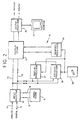
- Hitherto known editing systems vary from manufacturer to manufacturer but generally comprise the features shown in Figure 1 of the accompanying drawings. As shown in Figure 1 of the accompanying drawings a known editing system 1 comprises two
sources sources edit controller 5. The system 1 further comprises agraphics unit 6 such as the abovementioned system disclosed in our British patent GB-A-2 089 625 and aneffects unit 7 by which spatial transformations, such as those disclosed in our abovementioned British Patent GB-A-2 113 950, may be applied to video from one or both of thesources - The system 1 can be used to apply graphics and effects to video from one of the sources, for example the
source 2. In this mode of operation, a video clip is output a frame at a time from thesource 2 to the effects/graphics unit source 2 and the next frame in the clip is output to theunit monitor 8 so that the user can see the result of his modifications as they are made to the frame. - The system 1 can also be used to combine video clips from the two
sources edit controller 5 is made responsive to an edit decision list which identifies the location of each clip in the two sources by for example its start frame and end frame, the number of frames in the clip and where appropriate the frames between which a splice is to be made. A more sophisticated operation which may also be performed by the system 1 is that of combining two clips by dissolving between the two clips. In a dissolving operation the edit decision list includes data identifying the number of frames in a dissolve. In response thereto theedit controller 5 controls the mixer 4 to combine corresponding frames in the two clips, for example in a weighted summing of the frame data. During this mode of operation frames from thesource 2 may be modified by theeffects unit 7 before being passed to the vision mixer 4. - In all of the above discussed modes of operation the resulting video output from the mixer 4 may simply be displayed on the
monitor 8 or it may be stored to enable further work to be carried out subsequently. In the case where it is stored for subsequent work a further VTR (not shown) will be required to record the video output. A further VTR is necessary since both of thesource VTRs - The abovedescribed system 1 therefore may include a third VTR (not shown) which is used to record the combined clip output from the mixer 4. Such a system is known as a three machine edit suite, since it comprises three VTRs. A further VTR may be added to the system as a third source (not shown) to form a so-called four machine edit suite. During editing the third source is used to supply a moving black and white key, known as a "matte reel". The key is related to the image in a clip supplied by one of the
sources sources source 2 to the effects unit for combination with respective frames from thesource 3 by the vision mixer 4. - One drawback with the abovedescribed three and four machine edit suites is that often more than one operation is required to produce a desired result and this restricts artistic use of the system. Furthermore, it is impossible to create graphics dynamically, i.e. as the video clips are run and this prevents subtle integration of the graphics with the video resulting in a discernable difference between the live video and the off-line graphics. As a result, it is difficult to create first time around exactly what was intended and the creation process is therefore one of repeatedly working and reworking a piece until the desired result is achieved.
- Another drawback is related to the use of VTRs to supply and record video clips. VTRs are sequential access devices and cannot simultaneously playback and record different video clips. This means that a separate VTR is required as a source for each video clip to be worked on and at least one further VTR is required to record the video output from the mixer.
- We manufacture and sell an editing system under the trade mark "HARRY". In our HARRY system frames forming a video clip are digitally encoded and stored in disk stores. As is disclosed in our US Patent No. US-A-4 688 106, the video clips are read out of the disc stores in parallel. Whilst this arrangement provides greater flexibility by effectively allowing random access to the frames that constitute a clip, it nevertheless requires separate disc stores for each of the video clips.
- WO-A-91/14428 describes a data storage system having a local processor and a plurality of memory storage elements which is used for storing data from one or more external CPUs. The storage system includes a plurality of memory buffers, each coupled to a separate memory storage element. A data path control circuit is programmed by the local processor to control the transfer of data between the external CPUs and the memory buffers. Two interface circuits are coupled between the external CPUs and the memory buffers to provide two data paths for transferring data between the external CPUs and memory buffers (24). The data path control circuit contains two independent sequencing circuits for selecting memory buffers. This allows one data path to be used for reading or writing to a number of the memory buffers (24) while the other data path is simultaneously used for a different operation for the rest of the memory buffers (24).
- There is described in US-A-4 724 495 a real-time magnetic digital video disk recording system developed for applications in on-line digital imaging systems and off-line fast access image storage and retrieval buffers. The disk recorder uses high density recording technology and Winchester computer drive technology in a peripheral configuration which is fully synchronised to video system timing. The recorder includes two independent actuator and head assemblies for alternately recording successive video fields on separate tracks on separate zones A and B of a disk stack. Movement of one of the actuators and head assemblies is controlled and occurs within a field time to skip tracks containing media flaws to achieve real time digital video recording. The system bidirectionally receives and transmits data from buses of one size into buses of another size and formats the data into a recordable, compatible format, all under program control.
- The present invention in one of its aspects aims to overcome the above and associated problems by providing an electronic video store comprising:
- a store for storing digital data representing a multiplicity of different video frames which together form one or more video clips displayable on a monitor at a predetermined video frame data rate;
- two ports for receiving digital data for input to or output from the store, each port being operable simultaneously with the other to receive said digital data for input or output at the predetermined video frame data rate;
- an interface connected to said store and said two ports for transferring data therebetween; and wherein:
- said store comprises a plural number of disc storing units operable to transfer data at a disc data transfer rate, the number of disc storing units being sufficient to enable data to be transferred between said store and said interface at a total data transfer rate at least equal to the sum of the frame data rate for said ports, and
- said interface comprises a cache store for temporarily holding the video data to enable data from said two ports at said video frame data rate to be transferred to said number of disc storing units at said disc data transfer rate and to enable data from said number of disc storing units at said disc data transfer rate to be transferred to said ports at said video frame data rate.
-
- In an embodiment of the invention the interface enables random access to the stored video frames, so that one port might for example be used to read frames relating to one clip from the store whilst the other port is used simultaneously to read frames relating to a second clip from the store, thereby enabling simultaneous real-time processing and display of the two clips by the system.
- The combination of a random access store together with at least two input/output ports provides for a system of far greater flexibility than has hitherto been possible.
- In the practice of the invention each of the ports has sufficient bandwidth to enable at least one clip to be transmitted at video rate. Since there are at least two ports it is therefore possible to convey simultaneously frames relating to at least two video clips from the store for concurrent processing and/or display of the images represented thereby. Thus, the two ports enable a dissolve between two video clips to be made as the data is required, without the need to store the dissolve clip during its creation. This facilitates editing by allowing a dissolve to be previewed before the data therefor is committed to memory.
- The above and further features of the invention are set forth with particularity in the appended claims and together with advantages thereof will become clearer from consideration of the following detailed description of an exemplary embodiment of the invention given with reference to the accompanying drawings.
- In the drawings:
- Figure 1 is a schematic diagram of a prior art system as already described hereinabove;
- Figure 2 is a schematic diagram of a system embodying the invention;
- Figure 3 is a schematic diagram of a video store; and
- Figure 4 is an exemplary display of video frames generated by the system of Figure 2.
-
- Referring now to Figure 2 of the accompanying drawings there is shown an electronic
video processing system 10 in which video clip data is stored in avideo store 11. The video data is input to thevideo store 11 via aninput selector 12 which includes both ananalog input 13 and adigital input 14 to enable data to be input in either analog or digital format from an off-line bulk storage device or library (not shown) such as a VTR. The video clip data is stored in digital form in thevideo store 11 and the input selector therefore comprises a suitable converter for converting the incoming clip data into the required format. Theinput selector 12 is connected to thevideo store 11 via twobidirectional data paths video store 11. - The
video store 11 is shown in greater detail in Figure 3 of the accompanying drawings as comprising aconverter 17 which interfaces the twobidirectional paths buffers pack path disc pack video store 11 is therefore able to output in a frame period or store all the data for two full frames of video. - The
buffers compressor 17 to distribute data from the twobidirectional paths video store 11, and to combine data from the disc packs 20, 21 to thebidirectional paths store 11, the data relating to the two frames is read in one frame period from the disc packs 20, 21 via thebuffers compressor 17 where the data is reformed as two separate frames which are output separately, one on eachline compressor 17 frompaths buffers store 11 and the rest of thesystem 10, theconverter 17 and/or eachbuffer - The frame data may be distributed among the disc drives in any convenient order. For example one field of the frame may be delivered to buffer 18 and from there the chrominance of the field written to one disc drive in the
pack 20 and the luminance of the field written to the other disc drive in thesame pack 20. The other field of the frame would be delivered to theother disc pack 21 for storage therein in a similar manner. Thus, the elements of each frame are distributed among the four disc drives of the two disc packs 20, 21. - It will be appreciated from the foregoing that the video store is a truly random access frame store which thereby enables frames from different video clips to be accessed in a random order for output therefrom. The provision of two
bidirectional paths store 11 or for one frame to be written to while another is read from thestore 11. This enables asystem 10 of greater flexibility to be produced than has hitherto been possible. - Returning to Figure 2, the
system 10 further comprises adisplay store 22 which is connected via twobidirectional busses input selector 12. Thedisplay store 22 comprises a large scratch pad store for storing data relating to several frames of video and a display processor for processing the frame data therein to produce respective frames of reduced size for concurrent display at different portions of amonitor 25, as will be described in greater detail hereinafter. The store is able to output one piece of stored video simultaneously to several different places on the monitor. The display processor comprises two separate processing units for producing simultaneously images of reduced size from data supplied via the twobidirectional busses video store 11 and written directly to thedisplay store 22 at video rate for display on themonitor 25 either at full size or at half or quarter size. Alternatively video clips may be transferred from a bulk storage library (not shown) via theinput selector 12 to thedisplay store 22. Data from thedisplay store 22 is read by anoutput selector 26 and output to themonitor 25 for display. This enables the user to preview one or more video clips or to identify video clips stored off-line in a bulk store library (not shown) for transfer to thevideo store 11. Theoutput selector 26 also comprises both analog and digital outputs 26a, 26b, similar to the analog anddigital inputs input selector 12, to enable video clip data to be output in either analog or digital format to the bulk storage device for example. - In an editing mode of operation data relating to a plurality of video clips is read out from the video store 11 a frame at a time to the
video store 22 where the data is processed before being stored so as to enable several frames to be displayed simultaneously at different, overlapping, or shared, portions of themonitor 25, as will be described in greater detail hereinafter. The processed data is output from the display store in raster order for display on themonitor 25. The video store has associated with it avideo processor 27 and aneffects processor 28. Thevideo processor 27 is arranged to perform such operations as generating a keying signal, modifying colour, changing texture, and theeffects processor 28 generates spatial effects such as changes of size, position and spin to one or more frames of a video clip, which operations and effects all per se well known. Frames modified by thevideo processor 27 andeffects processor 28 are supplied or returned to thedisplay store 22 for display on themonitor 25. - Preferably the parameters controlling the operations executed by the
video processor 27 and theeffects processor 28 are variable from frame to frame. So-called key frames may be defined by the user and parameters for frames between key frames derived by interpolation. Alternatively the parameters controlling the operations of thevideo processor 27 can be fixed so that only parameters controlling the spin, position, size, etc. operations of theeffects processor 28 are variable. The use of key frames to define selected parameters is per se well known and is disclosed for example in our British Patent Application published as No. GB-A-2 223 910, the teachings of which are incorporated herein by reference. - The
display store 22 also has associated with it agraphics processor 29 which enables a user to paint into each frame as described in our abovementioned British Patent No. GB-A-2 089 625, and/or to create a key or stencil as described in our abovementioned British Patent No. 2,113,950. Thegraphics processor 29 is responsive to a user operable input device such as a stylus andtouch tablet combination 30, as indeed are thevideo processor 27 and theeffects processor 28. - During editing the video processor in the
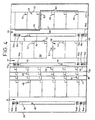
display store 22 is arranged to generate from the input video clips a display that represents an editing environment such as the display shown in Figure 4 of the accompanying drawings. As shown in Figure 4 of the drawings, the display is divided into three distinct workingareas area video clips 37 to 44. Of course more than three working areas could be displayed if so desired. A high definition television monitor for example has a wider aspect ratio (16 x 9) than normal broadcast television (4 x 3) and would be well suited to the display of four or even five reels. - Each
reel bar 34 to 36 includes amarker 45 to 47 which moves along the reel bar to provide an indication of the position of the displayed frames in relation to the clip as a whole and each displayed frame includes at its bottom right hand corner an information box, for example 48 to 56, to provide a further indication of the positions of the displayed frames in the video clips. The information in each box may for example be the number, i.e. position, of the frame in the clip or it may be time codes generated by a VTR when the frames were originally recorded. Each video clip can be worked on independently in each workingarea cursor 57 displayed on themonitor 8 as will be described in greater detail hereinafter. - The
cursor 57 is used to control many operations performed by thesystem 10. One function which thecursor 57 can be used to control is that of selecting which frames from a selected clip are displayed in the workingareas 31 to 33. The reel bars 34 to 36 each have associateddirection control icons 34a to d, 35a to e and 36a, to e. The reel bars, the control icons and the cursor are all generated by the processor within thedisplay store 22. Placing thecursor 57 over theicon 36a for example and pressing the stylus firmly on the touch tablet will cause the clip displayed inwork area 33 to scroll up whilst selectingicon 36b will cause the clip to scroll up to an event, such as a join, previously defined in the clip. Similar operations are performed by selection of the other icons as will be readily apparent to those possessed of the appropriate skills. When a scrolling icon is selected data relating to the appropriate video frames in the appropriate clip are read from thevideo store 11 to thevideo store 22. The data is processed to reduce the size of each frame and the processed data is then stored at locations in thestore 22 corresponding to the position of the reduced frame on themonitor 25. - Video clips to be edited are loaded from the bulk store (not shown) via the
input selector 12 to thevideo store 11. One of the bidirectional paths e.g. 15 is used to transfer the incoming video clip data to thevideo store 11 and this leaves the other path e.g. 16 free to transfer data relating to another video clip, for example a moving key associated with the first mentioned video clip. During the loading of clip data in thestore 11 the data is read simultaneously by thedisplay store 22 for display of the video on the monitor. Indeed, the video of both clips can be displayed at the same time either as two half size images duly processed by thedisplay store 22 on themonitor 25 or as full size images using two monitors. Selected frames of selected clips stored in thevideo store 11 can then be transferred to thevideo processor 27 andeffects processor 28 for processing and to thedisplay store 22 for display on themonitor 25. Since thevideo store 22 is effectively a random access frame store, the system can be made to display any frame from any clip or combination of frames and clips in any order and at any position on themonitor 25 without the need for the user to commit irretrievably to a particular displayed combination until such time as he is entirely happy with the result as displayed on the monitor. - Once the desired clip or clips have been loaded into the
video store 11 and selected frames therein displayed on themonitor 25 the user can edit the clips. Cut and insert editing, i.e. video splicing, is achieved for example by displaying frames of a first video clip to be inserted in say the workingarea 32, and frames of a second video clip, to be cut to receive the first clip, in the workingarea 33. The start of the first clip is identified by placing thecursor 57 between the first frame (forexample frame 58 in Figure 4) and its preceding frame and pressing the stylus down firmly on the touch tablet and thereafter moving the cursor rapidly to the right by corresponding rapid manipulation of the stylus on the touch tablet. This action is a cutting action known as swiping and is interpreted by theprocessor 27 as a command to cut the first video clip at the join betweenframe 58 and the preceding frame (indicated at 59 in Figure 4) to form an insert video clip (indicated at 42 in Figure 4). - The image of the
insert clip 42 can be attached to thecursor 57 by placing the cursor over thefirst frame 58 and pressing the stylus down on the touch tablet. Thereafter two dimensional movement of thecursor 57 on the monitor display results in corresponding movement of theinsert video clip 42 on the display. - The user is therefore free to move the
insert video clip 42 anywhere on the display screen and can for example move theinsert clip 42 into the workingarea 33 and position thefirst frame 58 thereof over aframe 60 of the second video clip displayed therein. With theinsert clip 42 so positioned, pressing the stylus down firmly on the touch tablet is interpreted by theprocessor 27 as a command to cut the second video clip at the join betweenframe 60 and the preceding frame (61 in Figure 4), and to join theinsert clip 42 onto the end of the second clip afterframe 61 thereof. - Once this operation has been performed by the processor a new clip is defined as a spliced combination of the frames of the second clip up to and including
frame 61 followed by all frames after and includingframe 58 of the first clip. A similar operation can be used to move a clip from one reel to another. If instead of placing thefirst frame 58 of the first clip over theframe 60 of the second clip, thefirst frame 58 is instead placed over the join between theframes frames - Since the cut and insert operation is performed in the
video processor 27 it therefore does not result in a corresponding change in the frame data in thevideo store 11. Accordingly,data defining frame 59 and the preceding frames in the first clip anddata defining frame 60 and subsequent frames in the second clip remain available for further processing if required. This availability of frames is indicated on the display by acontinuous line 62 which crosses the combined clip at the join between the first and second clips and connects between a pair oftails tail tail 64 indicates that the first two frames of the first clip do not form part of the combined clip and are available for further processing if required, and thetail 63 indicates that the last three frames of the second clip do not form part of the combined clip and are available for further processing if required. - Making frames available for further processing can be useful if the operator is not happy with the result obtained in the combined clip during preview when the clip is run and displayed as a video sequence. In order to facilitate user changes to the combined clip by changing the position of the join in the combined clip, the
processor 27 is made responsive to manipulation of the stylus and corresponding movement of thecursor 57 in the area of the join as represented by thecross bar 62. When the cursor is placed over thecross bar 62 and the stylus is pressed down firmly on the touch tablet, subsequent upward movement of thecursor 57 on the display screen causes the processor to insert in reverse order frames from the first clip and to remove in reverse order frames from the second clip. Thus, in Figure 4 upward movement of the cursor would causeframe 61 of the second clip to be replaced byframe 59 of the first clip. The length oftail 64 would decrease accordingly by one frame and the length oftail 63 would increase accordingly by one frame. Similar downward movement of thecursor 57 would result in the opposite change in frames occurring. Furthermore, hidden frames (i.e. frames represented by thetails 63, 64) in either clip can be displayed by placing thecursor 57 on thetail cursor 57 on the tail and swiping downwards along the tail. - The system is also arranged to facilitate replication of a clip or a portion of a clip. The clip or clip portion to be replicated is identified by placing the cursor over the first frame thereof, pressing the stylus down firmly on the touch tablet in order to connect the clip to the cursor and then pressing down again with the stylus to disconnect the cursor from the clip. The
display store 22 responds to this manipulation by replicating the identified frames in the store. The copy clip thus created is not displayed separately on the monitor but is conceptually held or displayed off-screen. The system is therefore arranged to enable the copy clip to be retrieved by swiping the cursor off one side of the screen. This causes the copy clip to be attached to the cursor and the copy can then be positioned as desired on the screen. - In addition to splicing two clips together, as discussed hereinabove, the
system 10 is able to dissolve between two clips over a selected number of frames. In a procedure similar to that already discussed hereinabove the first and last frames of two video clips are identified and the two clips are spliced together in one of the workingareas 31 to 33. A dissolve is then set over a selected number of frames, by placing thecursor 57 over thecross bar 62 at the join between the two clips and pressing down with the stylus. The system interprets this action as a command to create a dissolve. The command is acknowledged by thecrossbar 62 being displayed in a different colour. A menu is displayed on the monitor thereby enabling the user to enter data about the dissolve including its length and whether the dissolve starts at splice point as represented by thecrossbar 62, finishes at the splice point, or includes the splice point. Hidden frames that contribute to the dissolve are represented by respective portions of thetails video store 11 at this stage and the user is free to change the position of the join between the two clips as described hereinabove. - In some situations the user may wish to use only some of the hidden frames in the two clips, as represented by the
tails tails tails - Once a dissolve has been defined on the display screen, it can be previewed by running the combined clip containing the dissolve at video rate. A
further control icon 34e to 36e is displayed beneath respective reel bars 34 to 36 and enables the user to enter the preview mode. When theviewing control icon 34e to 36e is selected by use of the cursor the system responds by displaying at full size on the monitor the frame displayed nearest to the centre of the working space when the viewing icon was selected. A menu of functions (such as play, fast, forward, fast reverse, stop, etc.) is also displayed on the monitor and the selected clip can be previewed by the use by selection of the desired functions with the cursor. In this preview mode of operation frames comprising the first clip are read in order from one path e.g. 15 of thevideo store 11 and passed via thevideo processor 27 to thedisplay store 22 for display on themonitor 25. During the dissolve frames comprising the second clip are simultaneously read in order from thevideo store 11 via theother path 16 and are passed together with respective frames from the first clip to theprocessor 27. Respective frames from the first and second clip are combined in a weighted combination by thevideo processor 27 and the resulting combined frames are passed in order to thedisplay store 22 for display of the combined image on themonitor 25. - The above discussed previewing of a dissolve is made possible by the provision of a
video store 11 with twobidirectional paths video store 11 and this frees the user to experiment with different edits before making a commitment to a particular combination of clips. - The
system 10 also includes the facility to key together simultaneously several clips on a frame by frame basis. In the exemplary system described herein this keying facility is selected by moving thereel bar 35 to the right in Figure 4 thereby widening the workingarea 31 defined between reel bars 34 and 35. Video clips 37, 38, 39, 40 are each selected by use of the cursor and by manipulation of the stylus on the touch tablet as previously described. Selected clips are each brought into the workingarea 31 by further movement of the stylus and each new clip may be placed in front, behind, or between clips already displayed in the workingarea 31. Theclips 37 to 40 together form a stack and the position of eachclip 37 to 40 determines the rank or priority of the clip in the stack. Eachclip 37 to 40 can be manipulated independently or in combination with other clips in the stack. Thus, for example,clip 38 can be taken out of the stack by attaching thecursor 57 to the clip and moving it to workingarea 32. The clip can then be replicated or otherwise modified before being returned to its original position or another position in the stack. A clip can also be scrolled independently of other clips in the stack. Clips are connected to the cursor and moved sideways in the workingarea 31 until, for example,clip 38 does not overlap and is not overlapped by any of the other clips.Clip 38 can then be scrolled independently, as described hereinabove. - The system is arranged such that a group of coincident frames, corresponding ones from each of the clips in the stack, is available in the
display store 22 so that the composite result can be displayed on the monitor. This enables the user to preview the result before the clips are finally combined and committed to thevideo store 11, and to make corrections to individual clips so that the composite clip contains the desire result. For example, the colour correction in one clip can be adjusted so as to match the coloration in another of the clips while both clips or frames from both clips are displayed simultaneously. If desired one foreground clip,e.g. clip 37, can be viewed against the background clip,e.g. clip 40. - The
video processor 27 includes a keyer circuit (not shown) by which a blue screen key can be generated. Such a keyer circuit is disclosed in our US Patent No. US-A-4,667,221, the teachings of which are incorporated herein by reference. A user defined key or stencil may also be created by thegraphics processor 29 on a frame-by-frame basis for some or all frames in a selected clip. Previously defined key clips can be associated with respective video clips. Thedisplay store 22 is arranged to add data representing a black back-shadow to video clip data for which there is an associated key clip as the clip data is written to thedisplay store 22. The black backshadow (not shown) facilitates identification of a keyed clip when frames of the clip are displayed on themonitor 25. - When a stack is defined in the working
area 31 the key clips associated with the respective video clips are assigned a priority or rank such that when theclips 37 to 40 are combined, keyed features inclip 40 are seen in the foreground obscuring features in the other clips, whereas features in theclip 37 form the background and are obscured by keyed features in theother clips 38 to 40. - It should be noted that data relating to any clip displayed on the monitor can be transferred to the
effects processor 28 and/or thegraphics processor 29 for creation of a key, or indeed for modification by any of the other operations provided by the twoprocessors - Once the user is satisfied with the result of his editing, whether it be a simple cut and insert, a dissolve or a layered sequence of stacked clips with colour and texture changes to some of the clips therein, the resulting clip can be committed to memory. Clip data is read from the
video store 11 and combined frame by frame by theprocessors video store 11. - In the case of a simple cut and insert splice edit there is no combining as such to be performed by the
processors 27 to 29 and so the operation is simply one of re-indexing the frame data held in thestore 11. In the case of a dissolve edit it is necessary to combine two frames from different clips and so data for the two clips is read a frame at a time from thestore 11 along one of the paths,e.g. path 15, and the resulting combined frame data is written back to the store along the other of the paths,e.g. path 16. It will be appreciated that since each path only has sufficient bandwidth for one video channel the reading of frames for both clips viaonly path 15 will effectively halve the rate at which the two clips are read from thestore 11. However, this halving of the reading rate is unimportant since the combining operation corresponds to a final commitment by the user and can be performed without being displayed on themonitor 25. There will be a similar or greater reduction in speed when plural clips of a stack as abovedescribed are combined but again this reduction is unimportant to the working of the system. - Having thus described the present invention by reference to a preferred embodiment it is to be well understood that the embodiment in question is exemplary only and that modifications and variations such as will occur to those possessed of appropriate knowledge and skills may be made without departure from the scope of the invention as defined in the appended claims.
- For example, the four relatively high capacity disc drives in the video store could be replaced by a large number of smaller disc drives. An important consideration in the construction of the video store is that it should have sufficient bandwidth for at least two video clips, and more than two if so desired, to be transferred each at video rate. By increasing the number of disc drives comprising the
store 11 the complexity of transferring data will increase also. Random access to the frames stored in the discs can nevertheless be maintained by enlarging the cache stores in the buffers and/or the compressor, the size of the cache stores depending on the excess bandwidth and seek time of the discs, and on the number of clips to be transferred simultaneously at video rate. The video store may be used in a high definition television system simply by increasing the number of discs used and if necessary enlarging the cache stores.
Claims (6)
- An electronic video store comprising:and wherein:a store (20, 21) for storing digital data representing a multiplicity of different video frames which together form one or more video clips displayable on a monitor at a predetermined video frame data rate;two ports (15, 16) for receiving digital data for input to or output from the store, each port being operable simultaneously with the other to receive said digital data for input or output at the predetermined video frame data rate;an interface (17, 18, 19) connected to said store and said two ports (15, 16) for transferring data therebetween;said store comprises a plural number of disc storing units (20, 21) operable to transfer data at a disc data transfer rate, the number of disc storing units (20, 21) being sufficient to enable data to be transferred between said store and said interface (17, 18, 19) at a total data transfer rate at least equal to the sum of the frame data rate for said ports (15, 16), andsaid interface (17, 18, 19) comprises a cache store for temporarily holding the video data to enable data from said two ports (15, 16) at said video frame data rate to be transferred to said number of disc storing units (20, 21) at said disc data transfer rate and to enable data from said number of disc storing units (20, 21) at said disc data transfer rate to be transferred to said ports (15, 16) at said video frame data rate.
- A store as claimed in claim 1, comprising two disc storing units, and wherein each frame comprises two interleaved fields, and the interface (17, 18, 19) is arranged for transfer of data stored or to be stored in the disc storing units (20, 21) and arranged therein such that of each video frame, data representing one field is stored in one storing unit, and data representing the other field is stored in the other storing unit.
- A store as claimed in claim 2, wherein the interface (17, 18, 19) is arranged for transfer of data to or from each said storing unit (20, 21), said data being arranged such that each field is divided into chrominance and luminance data groups, which groups are stored in separate disc drives comprised in the respective disc storing unit.
- A store as claimed in any preceding claim, wherein the interface comprises at least two buffers (18, 19), equal in number to the number of disc storing units and respectively associated with the disc storing units for buffering data in transfer between each of the disc storing units (20, 21) and the two ports (15, 16).
- A store as claimed in claim 4, wherein the interface further comprises a converter (17) between the buffers (18, 19) and the two ports (15, 16), which converter (17) converts video data between a video format at said two ports (15, 16) and a storing format at said buffers (18, 19).
- A store as claimed in claim 4 or 5, wherein the buffers (18, 19) each comprise a cache store for accumulating a multiplicity of frames of data to facilitate the transfer of data between the two ports (15, 16) and the disc storing units (20, 21).
Applications Claiming Priority (3)
| Application Number | Priority Date | Filing Date | Title |
|---|---|---|---|
| GB9205503 | 1992-03-13 | ||
| GB9205503A GB2266037B (en) | 1992-03-13 | 1992-03-13 | An electronic video processing system |
| EP93301889A EP0560624B1 (en) | 1992-03-13 | 1993-03-12 | Electronic video system with simultaneous real-time processing |
Related Parent Applications (1)
| Application Number | Title | Priority Date | Filing Date |
|---|---|---|---|
| EP93301889A Division EP0560624B1 (en) | 1992-03-13 | 1993-03-12 | Electronic video system with simultaneous real-time processing |
Publications (3)
| Publication Number | Publication Date |
|---|---|
| EP0858216A2 EP0858216A2 (en) | 1998-08-12 |
| EP0858216A3 EP0858216A3 (en) | 1998-09-23 |
| EP0858216B1 true EP0858216B1 (en) | 2002-07-31 |
Family
ID=10712072
Family Applications (2)
| Application Number | Title | Priority Date | Filing Date |
|---|---|---|---|
| EP98200948A Expired - Lifetime EP0858216B1 (en) | 1992-03-13 | 1993-03-12 | An electronic video store |
| EP93301889A Expired - Lifetime EP0560624B1 (en) | 1992-03-13 | 1993-03-12 | Electronic video system with simultaneous real-time processing |
Family Applications After (1)
| Application Number | Title | Priority Date | Filing Date |
|---|---|---|---|
| EP93301889A Expired - Lifetime EP0560624B1 (en) | 1992-03-13 | 1993-03-12 | Electronic video system with simultaneous real-time processing |
Country Status (5)
| Country | Link |
|---|---|
| US (2) | US5808628A (en) |
| EP (2) | EP0858216B1 (en) |
| JP (1) | JP3492392B2 (en) |
| DE (2) | DE69332178T2 (en) |
| GB (1) | GB2266037B (en) |
Families Citing this family (80)
| Publication number | Priority date | Publication date | Assignee | Title |
|---|---|---|---|---|
| GB2266037B (en) * | 1992-03-13 | 1996-02-14 | Quantel Ltd | An electronic video processing system |
| CA2327070C (en) | 1992-07-01 | 2001-12-25 | Avid Technology, Inc. | Electronic film editing system using both film and videotape format |
| GB2273220B (en) * | 1992-12-07 | 1997-01-08 | Quantel Ltd | A video processing system |
| GB2300535B (en) * | 1995-04-10 | 2000-03-01 | Quantel Ltd | Electronic video processing system |
| US5982364A (en) * | 1993-03-12 | 1999-11-09 | Quantel, Ltd. | Video processing system including frame position indicators |
| US5440348A (en) * | 1993-04-16 | 1995-08-08 | Avid Technology, Inc. | Method and user interface for creating, specifying and adjusting motion picture transitions |
| JP3402659B2 (en) * | 1993-05-13 | 2003-05-06 | オリンパス光学工業株式会社 | Image handling equipment |
| US5727112A (en) * | 1994-01-07 | 1998-03-10 | Quantel Limited | Video processing apparatus and method |
| US5535137A (en) * | 1994-02-14 | 1996-07-09 | Sony Corporation Of Japan | Random access audio/video processor with compressed video resampling to allow higher bandwidth throughput |
| GB2287373B (en) * | 1994-03-04 | 1998-01-21 | Quantel Ltd | An image processing apparatus and method |
| AU685634B2 (en) * | 1994-07-05 | 1998-01-22 | Sega Enterprises, Ltd. | A video picture display apparatus and a game facility using it |
| DE69535330T2 (en) * | 1994-09-14 | 2007-05-31 | Intel Corporation, Santa Clara | Caching system with Explicit follow list |
| DE69616032D1 (en) * | 1995-02-23 | 2001-11-22 | Avid Technology Inc | SYSTEM FOR TAKING MOVING IMAGES USING NUMERICAL, NON-LINEAR MEDIA READABLE BY COMPUTER |
| US7623754B1 (en) | 1995-02-23 | 2009-11-24 | Avid Technology, Inc. | Motion picture recording device using digital, computer-readable non-linear media |
| US5673204A (en) * | 1995-07-06 | 1997-09-30 | Sun Microsystems, Inc. | Loopback video preview for a computer display |
| GB2306750B (en) * | 1995-10-23 | 1999-11-10 | Quantel Ltd | An audio editing system |
| GB2312139B (en) * | 1996-04-12 | 2000-09-20 | Sony Uk Ltd | Editing of recorded material |
| US6154601A (en) * | 1996-04-12 | 2000-11-28 | Hitachi Denshi Kabushiki Kaisha | Method for editing image information with aid of computer and editing system |
| GB2312138B (en) * | 1996-04-12 | 2000-09-20 | Sony Uk Ltd | Editing of recorded material |
| CA2201679A1 (en) * | 1996-04-15 | 1997-10-15 | Raju C. Bopardikar | Video data storage |
| US6154600A (en) * | 1996-08-06 | 2000-11-28 | Applied Magic, Inc. | Media editor for non-linear editing system |
| EP0843311A3 (en) * | 1996-11-15 | 2000-01-26 | Hitachi Denshi Kabushiki Kaisha | Method for editing image information with aid of computer and editing system |
| US6381741B1 (en) | 1998-05-18 | 2002-04-30 | Liberate Technologies | Secure data downloading, recovery and upgrading |
| US6604242B1 (en) | 1998-05-18 | 2003-08-05 | Liberate Technologies | Combining television broadcast and personalized/interactive information |
| US5991799A (en) | 1996-12-20 | 1999-11-23 | Liberate Technologies | Information retrieval system using an internet multiplexer to focus user selection |
| US6621524B1 (en) * | 1997-01-10 | 2003-09-16 | Casio Computer Co., Ltd. | Image pickup apparatus and method for processing images obtained by means of same |
| US6061462A (en) * | 1997-03-07 | 2000-05-09 | Phoenix Licensing, Inc. | Digital cartoon and animation process |
| GB2323734B (en) | 1997-03-27 | 2001-04-11 | Quantel Ltd | A video processing system |
| US6400371B1 (en) * | 1997-05-16 | 2002-06-04 | Liberate Technologies | Television signal chrominance adjustment |
| US6513116B1 (en) | 1997-05-16 | 2003-01-28 | Liberate Technologies | Security information acquisition |
| US7631188B2 (en) * | 1997-05-16 | 2009-12-08 | Tvworks, Llc | Hierarchical open security information delegation and acquisition |
| GB9715925D0 (en) * | 1997-07-29 | 1997-10-01 | Discreet Logic Inc | Video data transfer |
| GB9716033D0 (en) | 1997-07-30 | 1997-10-01 | Discreet Logic Inc | Processing edit decision list data |
| GB2330446A (en) * | 1997-08-01 | 1999-04-21 | Discreet Logic Inc | Editing image data |
| US6763523B1 (en) | 1998-04-03 | 2004-07-13 | Avid Technology, Inc. | Intelligent transfer of multimedia data files from an editing system to a playback device |
| US6577351B1 (en) | 1998-05-18 | 2003-06-10 | Liberate Technologies | Anti-aliasing television signals for display |
| WO2000004548A1 (en) * | 1998-07-14 | 2000-01-27 | Koninklijke Philips Electronics N.V. | Editing of digital video information signals |
| CN1867068A (en) | 1998-07-14 | 2006-11-22 | 联合视频制品公司 | Client-server based interactive television program guide system with remote server recording |
| TW465235B (en) | 1998-09-17 | 2001-11-21 | United Video Properties Inc | Electronic program guide with digital storage |
| US6766357B1 (en) | 1999-04-15 | 2004-07-20 | Avid Technology, Inc. | Apparatus and method for efficient transfer of multimedia data for playback |
| GB2349288B (en) * | 1999-04-16 | 2003-10-22 | Quantel Ltd | A video editing system |
| AU3712300A (en) | 1999-06-11 | 2001-01-02 | Liberate Technologies | Hierarchical open security information delegation and acquisition |
| US6473094B1 (en) * | 1999-08-06 | 2002-10-29 | Avid Technology, Inc. | Method and system for editing digital information using a comparison buffer |
| US8434113B1 (en) | 1999-10-06 | 2013-04-30 | Tvworks, Llc | Electronic commerce using streaming media |
| US7085995B2 (en) * | 2000-01-26 | 2006-08-01 | Sony Corporation | Information processing apparatus and processing method and program storage medium |
| WO2001056281A1 (en) * | 2000-01-26 | 2001-08-02 | Sony Corporation | Information processing device and processing method and program storing medium |
| US7441014B1 (en) | 2000-02-09 | 2008-10-21 | Tvworks, Llc | Broadcast distribution using low-level objects and locator tables |
| US7237197B2 (en) * | 2000-04-25 | 2007-06-26 | Microsoft Corporation | Method and system for presenting a video stream of a video streaming device |
| US6430582B1 (en) * | 2000-04-28 | 2002-08-06 | D4 Media, Inc. | Goal seeking engine and method for generating custom media presentations |
| JP3494127B2 (en) * | 2000-05-30 | 2004-02-03 | 日本電気株式会社 | Video display device |
| DE60135567D1 (en) | 2000-10-11 | 2008-10-09 | United Video Properties Inc | SYSTEMS AND METHOD FOR PROVISION OF DATA STORAGE IN SERVER IN A MEDIA-ON-REQUEST DELIVERY SYSTEM |
| US6964023B2 (en) * | 2001-02-05 | 2005-11-08 | International Business Machines Corporation | System and method for multi-modal focus detection, referential ambiguity resolution and mood classification using multi-modal input |
| CN1212731C (en) * | 2001-03-26 | 2005-07-27 | 松下电器产业株式会社 | Video signal processor and video camera |
| WO2002082379A1 (en) * | 2001-04-05 | 2002-10-17 | Fujitsu Limited | Information processing device, information processing method, medium, and program |
| GB2374747A (en) * | 2001-04-19 | 2002-10-23 | Quantel Ltd | An electronic editing system providing tactile feedback to a user |
| US6791788B2 (en) | 2001-06-29 | 2004-09-14 | Storage Technology Corporation | Segmented power strip for an automated robotic device and method for joining same |
| US6798612B2 (en) | 2001-06-29 | 2004-09-28 | Storage Technology Corporation | Power strip distribution system and method for an automated robotic device in a data storage system |
| US6668991B2 (en) | 2001-06-29 | 2003-12-30 | Sebastian Canaday | Redundant power supply system and method for an automated robotic device in a data storage system |
| US6751048B2 (en) | 2001-06-29 | 2004-06-15 | Storage Technology Corporation | Power rail distribution system and method for an automated robotic device in a data storage system |
| US6760644B2 (en) * | 2001-06-29 | 2004-07-06 | Storage Technology Corporation | System and method for transmitting communication signals to an automated robotic device in a data storage system |
| US6751040B2 (en) | 2001-06-29 | 2004-06-15 | Storagetechnology Corporation | Method for exchanging tape cartridges between automated tape cartridge libraries |
| US7161615B2 (en) * | 2001-11-30 | 2007-01-09 | Pelco | System and method for tracking objects and obscuring fields of view under video surveillance |
| US6600967B2 (en) * | 2001-12-20 | 2003-07-29 | Storage Technology Corporation | Automated physical disk storage and management |
| US7493646B2 (en) | 2003-01-30 | 2009-02-17 | United Video Properties, Inc. | Interactive television systems with digital video recording and adjustable reminders |
| KR20040071945A (en) * | 2003-02-07 | 2004-08-16 | 엘지전자 주식회사 | Image display device capable of controlling a subpicture and method thereof |
| US7496272B2 (en) * | 2003-03-14 | 2009-02-24 | Pelco, Inc. | Rule-based digital video recorder |
| JP2004355767A (en) * | 2003-05-30 | 2004-12-16 | Canon Inc | Reproducing device |
| US7471871B2 (en) * | 2003-08-25 | 2008-12-30 | Hewlett-Packard Development Company, L.P. | Index validation system and method |
| US20050275760A1 (en) * | 2004-03-02 | 2005-12-15 | Nvidia Corporation | Modifying a rasterized surface, such as by trimming |
| US7554538B2 (en) * | 2004-04-02 | 2009-06-30 | Nvidia Corporation | Video processing, such as for hidden surface reduction or removal |
| US8250034B2 (en) * | 2004-04-14 | 2012-08-21 | Verisign, Inc. | Method and apparatus to provide visual editing |
| CN101091175B (en) * | 2004-09-16 | 2012-03-14 | 辉达公司 | Load balancing |
| US7852353B1 (en) * | 2005-03-31 | 2010-12-14 | Apple Inc. | Encoding a transparency (alpha) channel in a video bitstream |
| EP2100440A4 (en) * | 2006-11-22 | 2010-06-02 | Staffan Soelve | A method for combining video sequences and an apparatus thereof |
| US20080301169A1 (en) * | 2007-05-29 | 2008-12-04 | Tadanori Hagihara | Electronic apparatus of playing and editing multimedia data |
| US10063934B2 (en) | 2008-11-25 | 2018-08-28 | Rovi Technologies Corporation | Reducing unicast session duration with restart TV |
| US8805418B2 (en) | 2011-12-23 | 2014-08-12 | United Video Properties, Inc. | Methods and systems for performing actions based on location-based rules |
| US9081491B2 (en) * | 2012-03-30 | 2015-07-14 | Corel Corporation | Controlling and editing media files with touch gestures over a media viewing area using a touch sensitive device |
| US8884906B2 (en) * | 2012-12-21 | 2014-11-11 | Intel Corporation | Offloading touch processing to a graphics processor |
| US11653072B2 (en) | 2018-09-12 | 2023-05-16 | Zuma Beach Ip Pty Ltd | Method and system for generating interactive media content |
Family Cites Families (27)
| Publication number | Priority date | Publication date | Assignee | Title |
|---|---|---|---|---|
| US4514818A (en) * | 1980-12-04 | 1985-04-30 | Quantel Limited | Video image creation system which simulates drafting tool |
| GB2113950B (en) * | 1982-01-15 | 1986-10-01 | Quantel Ltd | Image composition system |
| US4602286A (en) * | 1982-01-15 | 1986-07-22 | Quantel Limited | Video processing for composite images |
| US4724495A (en) * | 1982-11-15 | 1988-02-09 | Hedberg David J | Digital formatter, controller, and head assembly for video disk recording system, and method |
| GB8408113D0 (en) * | 1984-03-29 | 1984-05-10 | Quantel Ltd | Video editing/viewing systems |
| GB8420890D0 (en) * | 1984-08-16 | 1984-09-19 | Quantel Ltd | Video editing systems |
| KR910000365B1 (en) * | 1984-10-05 | 1991-01-24 | 가부시기가이샤 히다찌세이사꾸쇼 | Memory circuit |
| US4903227A (en) * | 1984-10-17 | 1990-02-20 | Mitsubishi Denki Kabushiki Kaisha | Processor for digitized video having common bus for real time transfer of input and output video data |
| US5175625A (en) * | 1985-04-20 | 1992-12-29 | Quantel Limited | Video image creation systems combining overlapping stamps in a frame period before modifying the image |
| GB8521563D0 (en) * | 1985-08-30 | 1985-10-02 | Quantel Ltd | Video signal processing systems |
| US4747047A (en) * | 1985-12-06 | 1988-05-24 | Unisys Corporation | Data transfer system using two peripheral controllers to access dual-ported data storage units |
| JP2523715B2 (en) * | 1987-11-27 | 1996-08-14 | 株式会社日立製作所 | Magnetic disk drive |
| GB8815182D0 (en) * | 1988-06-25 | 1988-08-03 | Quantel Ltd | Manipulating video image signals |
| JP2748562B2 (en) * | 1988-07-13 | 1998-05-06 | セイコーエプソン株式会社 | Image processing device |
| GB8822062D0 (en) * | 1988-09-20 | 1988-10-19 | Quantel Ltd | Video processing |
| US4972396A (en) * | 1988-10-24 | 1990-11-20 | Honeywell Inc. | Multiple independently positionable recording-reading head disk system |
| GB8910380D0 (en) * | 1989-05-05 | 1989-06-21 | Quantel Ltd | Video processing |
| GB8913638D0 (en) * | 1989-06-14 | 1989-08-02 | Quantel Ltd | Electronic image composition systems |
| GB2235856B (en) * | 1989-09-01 | 1993-11-17 | Quantel Ltd | Improvements in or relating to electronic graphic systems |
| JP3216810B2 (en) * | 1989-10-05 | 2001-10-09 | 富士ゼロックス株式会社 | Video data display system |
| US5185876A (en) * | 1990-03-14 | 1993-02-09 | Micro Technology, Inc. | Buffering system for dynamically providing data to multiple storage elements |
| US5237648A (en) * | 1990-06-08 | 1993-08-17 | Apple Computer, Inc. | Apparatus and method for editing a video recording by selecting and displaying video clips |
| GB2248362A (en) * | 1990-07-05 | 1992-04-01 | Rank Cintel Ltd | Multi-path digital video architecture |
| JP2698695B2 (en) * | 1990-09-07 | 1998-01-19 | 富士通株式会社 | Video editing device |
| JPH04129481A (en) * | 1990-09-20 | 1992-04-30 | Sony Corp | Special effect video image forming method |
| US5283560A (en) * | 1991-06-25 | 1994-02-01 | Digital Equipment Corporation | Computer system and method for displaying images with superimposed partially transparent menus |
| GB2266037B (en) * | 1992-03-13 | 1996-02-14 | Quantel Ltd | An electronic video processing system |
-
1992
- 1992-03-13 GB GB9205503A patent/GB2266037B/en not_active Expired - Lifetime
-
1993
- 1993-03-12 EP EP98200948A patent/EP0858216B1/en not_active Expired - Lifetime
- 1993-03-12 DE DE69332178T patent/DE69332178T2/en not_active Expired - Lifetime
- 1993-03-12 DE DE69332053T patent/DE69332053T2/en not_active Expired - Lifetime
- 1993-03-12 EP EP93301889A patent/EP0560624B1/en not_active Expired - Lifetime
- 1993-03-15 JP JP05378693A patent/JP3492392B2/en not_active Expired - Lifetime
-
1995
- 1995-06-06 US US08/467,755 patent/US5808628A/en not_active Expired - Lifetime
-
1998
- 1998-02-27 US US09/032,108 patent/US6144391A/en not_active Expired - Lifetime
Also Published As
| Publication number | Publication date |
|---|---|
| EP0560624A2 (en) | 1993-09-15 |
| EP0560624A3 (en) | 1994-01-05 |
| GB2266037B (en) | 1996-02-14 |
| GB9205503D0 (en) | 1992-04-29 |
| EP0858216A2 (en) | 1998-08-12 |
| DE69332053T2 (en) | 2002-10-17 |
| EP0858216A3 (en) | 1998-09-23 |
| US6144391A (en) | 2000-11-07 |
| EP0560624B1 (en) | 2002-06-26 |
| GB2266037A (en) | 1993-10-13 |
| JP3492392B2 (en) | 2004-02-03 |
| DE69332178D1 (en) | 2002-09-05 |
| DE69332053D1 (en) | 2002-08-01 |
| US5808628A (en) | 1998-09-15 |
| DE69332178T2 (en) | 2002-11-21 |
| JPH06121269A (en) | 1994-04-28 |
Similar Documents
| Publication | Publication Date | Title |
|---|---|---|
| EP0858216B1 (en) | An electronic video store | |
| EP0601749B1 (en) | A video processing system | |
| US6314231B1 (en) | Editing apparatus | |
| US6744968B1 (en) | Method and system for processing clips | |
| EP0737978A2 (en) | An electronic video processing system | |
| US6445874B1 (en) | Video processing system | |
| Brenneis | Final Cut Pro 3 for Macintosh | |
| US5982364A (en) | Video processing system including frame position indicators | |
| JP3773229B2 (en) | Moving image display method and apparatus | |
| US5175622A (en) | Apparatus and method for generating special effects by processing video signals from three sources | |
| GB2274223A (en) | A video editing system | |
| US20040136688A1 (en) | Video processing system | |
| JP2773370B2 (en) | Image display device | |
| JP5050424B2 (en) | Effect switcher and control method of video playback device in effect switcher | |
| Turner | SMPTE Tutorial: SMPTE Tutorial: 1,001 Questions to Ask before Deciding on a Nonlinear Video Editing System | |
| JPH0377710B2 (en) | ||
| JP3292509B2 (en) | Moving image reproducing apparatus and apparatus using the same | |
| Turner | 1,001 Questions to Ask before Buying a Non-Linear Editing System | |
| NL8100263A (en) | INTERACTIVE VIDEO PRODUCTION DEVICE AND METHOD. | |
| JP2000100128A (en) | Editing system and method | |
| JPH09102027A (en) | Medical picture display device | |
| JP2000100132A (en) | System and method for editing | |
| JPH05268603A (en) | Electronic conference device | |
| JP2000100130A (en) | System and method for editing | |
| JP2000100131A (en) | System and method for editing |
Legal Events
| Date | Code | Title | Description |
|---|---|---|---|
| PUAI | Public reference made under article 153(3) epc to a published international application that has entered the european phase |
Free format text: ORIGINAL CODE: 0009012 |
|
| PUAL | Search report despatched |
Free format text: ORIGINAL CODE: 0009013 |
|
| AC | Divisional application: reference to earlier application |
Ref document number: 560624 Country of ref document: EP |
|
| AK | Designated contracting states |
Kind code of ref document: A2 Designated state(s): DE FR GB |
|
| AK | Designated contracting states |
Kind code of ref document: A3 Designated state(s): DE FR GB |
|
| 17P | Request for examination filed |
Effective date: 19990316 |
|
| 17Q | First examination report despatched |
Effective date: 19991129 |
|
| RTI1 | Title (correction) |
Free format text: AN ELECTRONIC VIDEO STORE |
|
| GRAG | Despatch of communication of intention to grant |
Free format text: ORIGINAL CODE: EPIDOS AGRA |
|
| RTI1 | Title (correction) |
Free format text: AN ELECTRONIC VIDEO STORE |
|
| GRAG | Despatch of communication of intention to grant |
Free format text: ORIGINAL CODE: EPIDOS AGRA |
|
| GRAH | Despatch of communication of intention to grant a patent |
Free format text: ORIGINAL CODE: EPIDOS IGRA |
|
| GRAH | Despatch of communication of intention to grant a patent |
Free format text: ORIGINAL CODE: EPIDOS IGRA |
|
| GRAA | (expected) grant |
Free format text: ORIGINAL CODE: 0009210 |
|
| AC | Divisional application: reference to earlier application |
Ref document number: 560624 Country of ref document: EP |
|
| AK | Designated contracting states |
Kind code of ref document: B1 Designated state(s): DE FR GB |
|
| REG | Reference to a national code |
Ref country code: GB Ref legal event code: FG4D |
|
| REF | Corresponds to: |
Ref document number: 69332178 Country of ref document: DE Date of ref document: 20020905 |
|
| ET | Fr: translation filed | ||
| PLBE | No opposition filed within time limit |
Free format text: ORIGINAL CODE: 0009261 |
|
| STAA | Information on the status of an ep patent application or granted ep patent |
Free format text: STATUS: NO OPPOSITION FILED WITHIN TIME LIMIT |
|
| 26N | No opposition filed |
Effective date: 20030506 |
|
| PGFP | Annual fee paid to national office [announced via postgrant information from national office to epo] |
Ref country code: FR Payment date: 20120319 Year of fee payment: 20 |
|
| PGFP | Annual fee paid to national office [announced via postgrant information from national office to epo] |
Ref country code: GB Payment date: 20120307 Year of fee payment: 20 |
|
| PGFP | Annual fee paid to national office [announced via postgrant information from national office to epo] |
Ref country code: DE Payment date: 20120411 Year of fee payment: 20 |
|
| REG | Reference to a national code |
Ref country code: DE Ref legal event code: R071 Ref document number: 69332178 Country of ref document: DE |
|
| REG | Reference to a national code |
Ref country code: GB Ref legal event code: PE20 Expiry date: 20130311 |
|
| PG25 | Lapsed in a contracting state [announced via postgrant information from national office to epo] |
Ref country code: DE Free format text: LAPSE BECAUSE OF EXPIRATION OF PROTECTION Effective date: 20130313 Ref country code: GB Free format text: LAPSE BECAUSE OF EXPIRATION OF PROTECTION Effective date: 20130311 |