FIELD OF THE INVENTION
The present invention relates to optical data recording. More
particularly, the present invention relates to utilizing a signal generated during
recording and indicative of mark formation effectiveness to control the position of a
recording spot relative to a tracking structure on a recording medium.
BACKGROUND OF THE INVENTION
In optical data recording, an optical source, typically a laser or laser
diode, generates an incident write signal in the form of a radiation beam. The beam is
applied to an optical medium to record data thereon as optically-detectable marks. To
facilitate proper application of the beam to the medium, certain types of media, such as
compact disk recordable (CD-R) media, include a preformed spiral tracking structure
typically referred to as a groove or pregroove. The spiral groove may be "wobbled" in
a radial direction of the disk about an average groove centerline in order to provide
rotational velocity and beam position information in a well-known manner. The
dimensions and shape of the groove can vary depending upon the medium, but an
exemplary groove width is on the order of 0.4 micron in the radial direction, with
adjacent grooves in the spiral separated by about 1.6 microns in the radial direction. In
CD-R media, the groove corresponds to a data track on which marks are recorded.
The quality of recorded data in many optical recording systems is
generally very sensitive to the cross-track position of the recording spot on the
medium. In a CD-R system, for example, data quality rapidly deteriorates when the
recording spot deviates from the centerline of the disk groove. A commonly-used
technique for maintaining a recording spot on-track is referred to as push-pull tracking.
This technique involves measuring an interference pattern caused by the interaction of
the recording spot with the groove or other suitable tracking structure on the recording
medium to generate a push-pull tracking signal. A tracking servo adjusts the position
of the recording spot to keep the push-pull signal at a predetermined optimum value
generally referred to as a "tracking offset" or an on-track value. The tracking offset is
intended to compensate for static errors such as detector misalignment and optical axis
tilt. Prior art techniques typically determine the tracking offset during a calibration
period before data recording. One common approach is to make a series of trial
recordings.
US-A-5,440,534, assigned to the present assignee and incorporated by
reference herein, discloses a technique for determining the tracking offset in an optical
recorder by correlating a mark formation effectiveness (MFE) signal generated during
one or more trial recordings with a corresponding push-pull tracking signal. This
technique recognizes and makes use of the fact that certain characteristics of the
reflected write signal vary with cross-track position of the recording spot, thereby
providing a number of advantages over other techniques. For example, the tracking
offset can be determined in a single recording pass, as compared to separate record and
read passes required by two-pass techniques. In addition, the resulting tracking offset
is optimized for recording rather than for reading. With this method, "on-track" is
defined as the cross-track position with the highest MFE signal.
The mark formation effectiveness signals described in US-A-5,440,534
are hereafter termed "density-based" methods. These methods are based on a single
reflected write signal which is generated from light received in substantially all of the
return aperture. The above-referenced commonly-assigned U.S. patents describe
techniques for measuring mark formation effectiveness that are fundamentally different
from prior art "density-based" methods. These new techniques, hereafter referred to as
"diffraction-based" methods, are based on reflected write signals generated from light
received in different zones of the return aperture. A mark formation effectiveness
signal is derived by comparing these reflected write signals. Diffraction-based methods
can also be combined with the prior art density-based techniques for improved
measurement signal-to-noise and more accurate prediction of the resulting written
mark quality.
The push-pull tracking method described above is referred to as a
"single spot" technique in that the spot that records and reads data also generates the
tracking signal. This reduces system cost and complexity when compared with
multi-spot tracking techniques. However, push-pull tracking also suffers from a
number of problems. For example, the tracking offset can vary with conditions such as
media tilt, lens decenter, optical spot aberrations, and groove asymmetry. These
conditions can change from disk to disk and from point to point on a given disk. The
tracking offset determined during a calibration period may therefore be unable to keep
the recording beam sufficiently on-track in the presence of the changing conditions that
can arise during actual data recording. Although the push-pull technique is used as an
example, it should be understood that other tracking methods, both "single spot" and
"multiple spot" are vulnerable to tracking errors from these effects as well.
As is apparent from the above, a need exists for a dynamic tracking
technique in which a recording beam is maintained on-track using mark formation
effectiveness information generated during actual data recording.
US-A-4,118,735 (Wilkinson) and US-A-4,322,837 (Mickelson et. al.)
describe a dynamic tracking technique in which a read-back beam is continuously
moved back and forth or "dithered" in a cross-track direction. This repetitive cross-track
motion is correlated with any resulting variation in the intensity of the light
reflected by the medium. When there is no correlation between cross-track motion and
reflected light variations, the read-back beam is considered to be "on-track". This
cross-track position corresponds to a minimum of the reflected light intensity for a
"burn dark" medium (burn dark being defined as a medium where written marks are
less reflective than unwritten lands). When there is any correlation between cross-track
motion and reflected light variation, the relative phase (positive or negative) of
the two signals is an indication of which side of "on-track" the read-back beam is
located.
US-A-Patent 5,434,834 (Shinoda et. al.) describes a similar method to
keep a light beam on-track. It differs from US-A-4,118,735 and US-A-4,322,837 in
that repetitive cross track motion is no longer achieved by dithering the illuminating
beam. Rather, it is produced by the periodic side-to-side wobble of a pre-groove, such
as found in recordable compact disk (CD-R) media. This relative cross-track motion
between illuminating beam and recording medium is detected using well known
methods such as push-pull techniques described above. As with US-A-4,118,735 and
US-A-4,322,837, a tracking signal is derived by correlating this cross-track motion
with variations in the reflected light intensity. Also, as with US-A-4,118,735 and US-A-4,322,837,
"on-track" is defined as a minimum in reflected light intensity.
Mark formation effectiveness measurement is preferable to detecting
reflected light intensity for a number of reasons. For example, the reflected light
intensity depends directly on the specific write pulse pattern being recorded. Such data
dependent fluctuations reduce measurement signal-to-noise as compared with an MFE
signal, which is a specific measured characteristic of reflected write pulses and is much
less dependent on data pattern. Also, the maximum MFE signal may not occur at the
same cross-track position as the minimum reflected light intensity.
With certain recording systems, however, there is relatively little change
is total reflected light intensity during mark formation. With these systems, density-based
DRDW techniques will produce low signal-to-noise MFE signals.
SUMMARY OF THE INVENTION
The present invention generates a tracking error signal (TES) during
actual data recording by correlating a diffraction-based mark formation effectiveness
(MFE) signal with a position signal indicative of relative cross-track movement
between a recording spot and a tracking structure on a recording medium. The TES is
used by a tracking servo in an optical recording system to keep the recording spot
on-track. The tracking servo may use the TES of the present invention either alone or
in conjunction with a conventional tracking signal such as a push-pull signal. The
diffraction-based MFE signal corresponds to a monitored characteristic of a reflected
optical recording beam, and provides an indication of whether marks have been
properly formed on the medium. Diffraction-based MFE techniques compare reflected
write signals received in different zones of the return aperture. They differ from prior
art density-based MFE methods which determine a characteristic of a single reflected
write signal received in substantially all of the return beam aperture. It is to be
understood that in the current invention diffraction-based methods include techniques
that are combinations of density-based and diffraction-based methods. The present
invention is applicable to any optical recording medium in which a diffraction-based
MFE signal generated during recording varies with the cross-track position of the
recording spot.
In accordance with one aspect of the invention, an apparatus is
provided for use in an optical recording system in which an incident beam records data
on a medium in the form of marks. A diffraction-based MFE signal is generated by
monitoring reflected write signals received in different zones of the return aperture and
is indicative of a characteristic of the marks formed on the medium. A position signal
is generated to provide an indication of a cross-track movement of the incident beam
relative to a tracking structure such as a wobbled groove on an optical disk recording
medium. Variations in the diffraction-based MFE and position signals are then
correlated to provide a dynamic TES. The diffraction-based MFE and position signals
are first band pass filtered and then correlated by, for example, using a multiplier
circuit to multiply the two signals together. Another approach is to use the position
signal to control application of the band-pass filtered diffraction-based MFE signal to
particular inputs of a signal difference circuit.
The position signal in accordance with the present invention can be
generated using a number of different techniques. The position signal is generally
indicative of relative cross-track motion between the incident beam recording spot and
a desired on-track position which may correspond to, for example, a centerline of a
tracking structure on the medium. The relative cross-track motion can be provided by,
for example, moving the recording spot in a predetermined cross-track pattern using a
drive signal applied to a tracking actuator. In such an embodiment, the position signal
may correspond to the drive signal applied to move the actuator or to a detected push-pull
signal indicative of the motion of the recording spot. Alternatively, relative
cross-track motion of the tracking structure beneath the recording spot can be detected
to provide a position signal. This type of relative cross-track motion may be provided,
for example, by the wobbled groove tracking structure of a recordable compact disk
(CD-R) medium. The present invention provides a dynamic TES using a diffraction-based
MFE signal measured during actual data recording and a position signal
corresponding to, for example, the time-varying AC component of a detected push-pull
position signal. Offset errors of the prior art associated with the DC component of the
push-pull signal are thereby avoided. This provides improved correction for static
errors such as detector misalignment or optical axis tilt. In addition, the TES of the
present invention adapts more accurately than prior art push-pull signals to changing
conditions such as media tilt, lens decenter, optical spot aberrations, and groove
asymmetry. Furthermore, the dynamic tracking of the present invention does not
require generation of an offset value or set of offset values during a calibration period.
The present invention is superior to prior art techniques which correlate changes in a
cross-track position signal with changes in the intensity of light reflected by the
recording medium. By extracting a characteristic from the reflected write signal that is
indicative of mark formation effectiveness, the present invention provides higher
measurement signal-to-noise and a more accurate indication of optimum cross-track
position. The diffraction-based MFE techniques of the current invention allow the
dynamic tracking method to be applied to recording systems which have inadequate
density-based MFE signals.
Further features of the invention, its nature and various advantages will
become more apparent from the accompanying drawings and following detailed
description of the invention.
BRIEF DESCRIPTION OF THE DRAWINGS
FIG. 1 is a block diagram of an optical recording system in which the
dynamic tracking control of the present invention may be implemented;
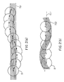
FIG. 2a illustrates cross-track motion of a recording spot relative to a
non-wobbled tracking structure of a recording medium;
FIG. 2b illustrates a cross-track motion of a wobbled groove tracking
structure relative to a recording spot;
FIG. 3 is a side sectional view of a groove structure of a recordable
compact disk (CD-R) medium;
FIG. 4 is a plot of diffraction-based mark formation effectiveness
(MFE) signal variations during recording as a function of the cross-track position of
the groove relative to the recording spot;
FIG. 5 illustrates an exemplary diffraction-based MFE technique that
may be used to generate a dynamic tracking signal in accordance with the present
invention;
FIG. 6 illustrates three exemplary sample recording spot positions
relative to a wobbled groove of a CD-R medium;
FIG. 7 is a plot of diffraction-based MFE signal variations during
recording for the three different recording spot positions shown in FIG. 6;
FIGS. 8a and 8b show plots of relative cross-track motion and
diffraction-based MFE signal variations, respectively;
FIG. 9 is a block diagram of an exemplary tracking error signal (TES)
generator in accordance with the present invention; and
FIG. 10 is a block diagram of another exemplary TES generator in
accordance with the present invention.
DETAILED DESCRIPTION OF THE PREFERRED EMBODIMENTS
FIG. 1 shows an optical recording system 10 in accordance with the
invention. The recording system 10 includes an optical source 11 for generating an
incident optical write signal. The optical source 11 may be, for example, a laser, laser
diode or LED. The optical source 11 is intensity-modulated by a stream of recording
data, such as digital audio, video or other information, suitably encoded to facilitate
recording on the optical medium. A data source (not shown) supplies the encoded
recording data, generally in the form of a stream of pulses, to optical source 11. An
exemplary data encoding technique well-known in the art is the eight-to-fourteen bit
modulation (EFM) code typically used in CD-R recording. The incident optical signal
typically includes a series of incident write pulses, each corresponding to a portion of
the recording data.
The incident optical signal passes through beam shaping optics 12 and
is reflected by a beam-directing surface of beam splitter 13 toward an optical recording
medium 14. Although particularly well-suited for tracking on a CD-R disk with a
wobbled groove, the invention is more broadly applicable to any recordable medium
which includes an optically-detectable tracking structure. The term "wobbled groove"
as used herein should therefore be understood to include any optically-detectable
structures arranged on a surface of a medium and suitable for generating relative cross-track
motion in accordance with the invention.
The incident beam is applied to medium 14 via an objective lens 15
mounted on a focus actuator FA. Focus actuator FA is designed to move objective
lens 15 in a direction perpendicular to the surface of medium 14 in order to change the
focus of the recording spot on the medium. A tracking actuator TA is operative to
move those parts of the system which are within or part of a housing 16, such as the
objective lens 15, beam splitters 13, 18, and photodetector assemblies 19, 20, in
response to a control signal from a servo control system 17. Tracking actuator TA
thereby moves the incident recording beam laterally across medium 14 in order to
maintain the beam in an on-track position with respect to the tracking structure of
medium 14. Alternatively, the tracking function may be accomplished by moving only
objective lens 15 in a lateral direction. Tracking and focus actuators TA and FA may
include, for example, various well-known arrangements of coils and electro-magnets
(not shown) controlled by servo control system 17 in a conventional manner. The
servo control system 17 operates the tracking actuator in response to the dynamic
tracking error signal (TES) of the present invention generated in a manner to be
described in greater detail below. The servo control system 17 may also receive a
conventional push-pull tracking signal directly from a position signal generator 25 as
shown in FIG. 1. In such an embodiment, the tracking servo utilizes both the dynamic
TES of the present invention and a conventional push-pull tracking signal.
A return beam reflected and diffracted from the recording medium 14 is
used for various functions such as tracking and focus detection and mark formation
effectiveness (MFE) measurement. The exemplary return beam path of Figure 1 shows
one of many possible ways to accomplish these functions. In this example, the return
beam passes through the lens 15 and the first beam splitter 13 and is applied to a
second beam splitter 18. The return beam is separated by beam splitter 18 into two
components. A first component is applied to a detector array 19 which includes, in
this example four elements: D1, D2, D3, and D4. The detector elements D1, D2, D3,
and D4 generate detected signals d1, d2, d3, and d4, respectively. Detector array 19
provides signals for tracking detection and MFE measurements. A second component
of the return beam is directed to a focus photodetector assembly 20 via a collimating
lens 22 and a limiting aperture 21. The focus photodetector assembly 20 is used to
generate a focus error signal for controlling the position of the objective lens 15.
The four detected signals d1, d2, d3, and d4 are applied to position
signal generator 25 and mark formation effectiveness (MFE) signal generator 23.
The position signal generator 25 receives the four detected signals d1,
d2, d3, and d4 from detector array 19 and generates a conventional push-pull signal
therefrom. Signal generator 25 will typically add detected signals d1 and d3 to form a
signal representing light received in one side of the return aperture. Similarly, detected
signals d2 and d4 will be added to form a sum signal representing light received in the
other side of the return aperture. The return aperture is thus effectively divided into
two halves in the cross-track direction. The sum signals from each half of the aperture
are then used to form a conventional push-pull signal by, for example, taking their
difference. In an alternative embodiment in a system utilizing a wobbled-groove
medium, the position signal generator output may also be sent to an absolute-time-in-pregroove
(ATIP) detection circuit (not shown). Other alternative embodiments of the
invention may utilize a position signal generator that does not receive detected signals
dl and d2 and instead generates a signal suitable for driving a tracking actuator to
thereby provide relative cross-track motion.
For the diffraction-based MFE signal of this example, the return
aperture is effectively divided into two halves in the in-track direction. The MFE
signal generator 23 in this embodiment will typically add detected signals d1 and d2 to
form a signal representing light received in one half of the return aperture. Similarly,
detected signals d3 and d4 will be added to form a sum signal representing light
received in the other half of the return aperture. The sum signals from the front and
rear of the aperture are then used to form a diffraction-based MFE signal by, for
example, taking their ratio. It should be noted that this is only one exemplary way of
generating a diffraction-based MFE signal.
The present invention utilizes a relative cross-track position signal and a
diffraction-based MFE signal to provide dynamic tracking error detection and tracking
position control in the optical recording system of FIG. 1. The cross-track position
signal is generated by providing relative cross-track motion between the recording spot
and the tracking structure of the recording medium. A tracking error signal is then
generated by detecting the resulting variations in the diffraction-based MFE signal, and
correlating the diffraction-based MFE signal variations to variations in the position
signal.
FIGS. 2a and 2b illustrate two exemplary techniques for generating the
cross-track position signal of the present invention. The views shown are looking
down on an optical disk in a direction normal to its laser-incident surface. In FIG. 2a,
a recording spot S1 is focused on a non-wobbled tracking structure TS1. The spot S1
typically has a width of greater than 0.5 microns and less than 2.0 microns, but can of
course vary depending upon the application. The tracking structure shown may
correspond to a pre-formed groove in which marks are recorded during the recording
process. A disk which includes the data track corresponding to tracking structure TS1
is rotated past the stationary recording beam at a desired velocity, such that S1 moves
relative to the disk. Movement of spot S1 back and forth across the tracking structure
TS2 is shown in FIG. 2a as a series of subsequent overlapping spots. An arrow in the
center of each spot indicates the direction of movement of the recording beam relative
to the recording medium. This relative cross-track motion could be provided by, for
example, supplying an appropriate drive signal to the tracking actuator in the system of
FIG. 1. In such an embodiment, the position signal can therefore be obtained from
tracking actuator drive circuitry acting as a position signal generator. Although the
cross-track motion of the recording spot shown in FIG. 2a is substantially sinusoidal, it
should be noted that the present invention may utilize any of a number of other
repetitive patterns to provide suitable cross-track motion.
FIG. 2b illustrates generation of relative cross-track motion by variation
in the tracking structure relative to a focused recording spot. The recording spot S1 is
focused on tracking structure TS2 which in this example corresponds to a wobbled
groove. As in FIG. 2a, the movement of spot S1 relative to TS2 is indicated by a
series of subsequent overlapping spots, and each overlapping spot has an arrow in its
center indicating the direction of movement of the recording beam relative to the
medium. In this example, the groove wobble provides relative cross-track movement
between the spot and the tracking structure. Again, although a wobbled groove
tracking structure is usually substantially sinusoidal as shown in FIG. 2b, other
repetitive variations in the tracking structure could be used to provide the desired
relative cross-track motion.
The wobbled groove tracking structure will now be described in greater
detail. As noted above, CD-R media typically include a wobbled groove such as that
shown in FIG. 2b. The wobbled groove corresponds to a data track on which marks
are intended to be recorded. The dimensions and shape of the groove can vary
depending upon the medium, but a typical groove width is on the order of 0.4 micron
in the radial direction of the disk, with adjacent grooves in the spiral separated by
about 1.6 microns in the radial direction. It should be noted that the amount of groove
wobble is exaggerated in FIG. 2b for illustrative purposes. The deviation of the
wobbled groove from a groove centerline CL1 is referred to as the wobble amplitude.
The wobble amplitude for CD-R media is typically on the order of 60 nm peak-to-peak,
and the average spatial wavelength of the groove is on the order of 60 microns.
The groove wobble is generally used to provide rotational velocity and
beam position information. When a wobbled-groove disk is rotated at, for example, a
constant linear velocity of 1.4 meters/second, the wobble amplitude variation will
modulate a push-pull tracking signal at a predetermined frequency. For CD-R media in
systems operating at a write speed of 1X or 4.32 Mbits/sec, the wobble frequency is
22.05 kHz. The wobble frequency is scaled upward for systems operating at higher
speeds such that, for example, a system operating at a 6X write speed will have a
wobble frequency six times higher than that of a 1X system, or 132.30 kHz. A servo
loop can then provide the desired disk rotational velocity by controlling the disk motor
to maintain the tracking signal modulation at the wobble frequency.
The beam position on the surface of a wobbled-groove disk is provided
by frequency-modulating the wobble. The modulation of the push-pull signal will then
vary about the wobble frequency in accordance with the frequency modulation applied
thereto. In CD-R systems, the frequency modulation of the groove wobble may be, for
example, on the order of plus and minus five percent. The information frequency-modulated
onto the groove wobble is often referred to as absolute-time-in-pregroove
(ATIP) information. The ATIP information typically includes binary data indicating
the amount of time the beam would have spent in the spiral groove to reach a given
position on the disk surface by following the groove from its beginning at the inner
disk diameter. The time may be represented in minutes, seconds and frames, with a
frame corresponding to, for example, 1/75 of a second at a write speed of 1X. The
ATIP modulation may also include other information such as a disk identifier,
synchronization marks and the expected optimum recording power. ATIP is described
in greater detail in U.S. Patent No. 5,363,360, which is assigned to the present
assignee and incorporated herein by reference.
When the tracking structure varies relative to the spot, as in the
wobbled groove example of FIG. 2b, the relative cross-track motion is detected to
provide a position signal. CD-R systems typically detect the groove wobble and any
modulation thereon using a technique similar to that used to provide a conventional
push-pull tracking signal. The resulting detected signal may be an ATIP wobble signal
used to provide rotational velocity control and beam position information as described
above. It should be noted that both ATIP detection and the dynamic tracking of the
present invention generally utilize the time-varying component of the detected groove
wobble, hereinafter referred to as the AC component. Information on the absolute
position of the tracking structure relative to the recording spot is usually not needed
and, in view of the tracking offset problems described previously, may be unreliable
under certain system operating conditions.
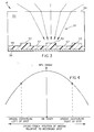
FIG. 3 illustrates a partial side sectional view of an exemplary CD-R
medium 14. The medium 14 includes a transparent polycarbonate substrate 50 having
an upper surface 54. A recording beam 52 is incident on the surface 54 of the
substrate 50 and is focused onto a groove 53. Substrate 50 overlies an absorptive dye
recording layer 55 and a gold reflective layer 56. As noted above, data is recorded in
the dye layer 55 by beam 52 in the form of optically-detectable marks within groove
53. The gold reflective layer 56 provides the high reflectivity required for reading back
the recorded data. It can be seen from FIG. 3 that the dye layer 55 is thicker in the
grooves 53 than it is in the areas 57 between the grooves. This is one factor which can
produce detectable variations in a diffraction-based MFE signal at a constant write
power level as the recording beam moves from an on-track to an off-track position.
FIG. 4 is a plot of diffraction-based MFE signal variation during
recording as a function of the cross-track position of the groove relative to the
recording spot. It can be seen that the diffraction-based MFE signal during recording
is at a maximum when the recording beam spot is on-track, that is, centered on the
wobbled groove. As the beam moves off-track to either side of the groove centerline,
the diffraction-based MFE signal decreases in magnitude as shown. The present
invention utilizes these diffraction-based MFE signal variations to provide a dynamic
tracking error signal in a manner to be described below.
FIG. 5 illustrates the generation of an exemplary diffraction-based MFE
signal suitable for use with the present invention. As discussed above, a diffraction-based
MFE measurement involves detecting reflected write signals in different zones of
the return aperture. For the example of Figure 5, reflected write signals will be
generated using the detector configuration shown in Figure 1. The two sum signals J
and K represent reflected write signals from light received in the front and rear of the
return aperture. These two signals are sampled at a time ΔT after the start of the
write pulse. The ratio of these sampled signals, JΔT/KΔT is one exemplary way to
generate a diffraction-based MFE signal. It should be understood that this exemplary
diffraction-based MFE signal is only one of many possible ways to measure mark
formation effectiveness using the present invention. Other examples of diffraction-based
MFE signal generation include:
- different sampling times such as after the end of the reflected write pulse
- different schemes for partitioning the return aperture
- different ways of signal processing such as averaging signals over a time
interval instead of sampling at a discrete time
- unequal weighting when combining signals from different zones of the
return aperture
- using a single reflected write signal from only a portion of the return
aperture
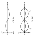
FIGS. 6, 7, 8a and 8b illustrate the operation of an exemplary
embodiment of the present invention in which relative cross-track motion is provided
by a wobbled groove of a CD-R medium. FIG. 6 shows a portion of the wobbled
groove tracking structure TS2 with recording spot S1 in three different positions A, B
and C relative to groove centerline CL1. In position A, the groove centerline CL1 is
to the left of the recording spot S1. In position B, the spot is centered on the groove
centerline CL1 and will generally track along CL1 since the wobble frequency is too
high for the recording spot to follow instantaneously. In position C, CL1 is to the
right of the spot.
FIG. 7 is a plot of the resulting diffraction-based MFE signal variations
for each of the recording spot positions A, B and C of FIG. 6. The relative cross-track
motion for each of the spot positions is provided by the wobbled groove and is shown
as DX on the horizontal axis. In this embodiment, the position signal corresponds to
the detected groove motion at the wobble frequency and is generally the same for each
of the three spot positions A, B and C. The corresponding diffraction-based MFE
signal variations, however, are different for each spot position and are shown as DYA,
DYB and DYC for the spot positions A, B and C, respectively. The present invention
utilizes these differences in diffraction-based MFE signal variation to provide a
dynamic tracking error signal (TES).
FIGS. 8a and 8b show in greater detail the position signal variation DX
and diffraction-based MFE signal variation DY, respectively, for each of the spot
positions A, B and C of FIG. 6 over one cycle of the groove wobble. The diffraction-based
MFE signals variations DYA and DYC are measured relative to diffraction-based
MFE signal values YA1 and YC1, respectively, as shown in FIG. 7, which are
the diffraction-based MFE values for positions A and C, respectively, when the
position signal DX is at its average value corresponding to the groove centerline. For
spot position B, which corresponds to the desired on-track position, the diffraction-based
MFE signal variation DYB is the same when the groove moves to the left
relative to the spot as it is when the groove moves to the right relative to the spot. For
spot position A, the diffraction-based MFE signal variation DYA is negative when the
groove moves to the left (farther from the spot) and positive when the groove moves
to the right (closer to the spot). For spot position C, the diffraction-based MFE signal
variation DYC is positive when the groove moves to the left and negative when the
groove moves to the right. The present invention correlates the position signal
variations DX, in this embodiment representing the movement of the groove relative to
the recording spot, with the diffraction-based MFE signal variations DY. The
correlation of DX and DY provides a dynamic TES which can be used to maintain the
recording spot on-track relative to the groove centerline.
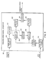
FIG. 9 is an exemplary embodiment of a TES generator 30 which
implements the correlation of position signal variations DX and diffraction-based MFE
signal variations DY. The position signal X is supplied from position signal generator
25 of FIG. 1 and may be, for example, a conventional push-pull signal. Alternatively,
the position signal X may correspond to an actuator drive signal generated by a
tracking servo for application to a tracking actuator. The position signal X is filtered
in band pass filter (BPF) 150 and then digitized in digitizer 152. For a CD-R system,
the BPF 150 may be centered at the fundamental groove wobble frequency and may
have a passband suitable for passing any FM modulation of the wobble frequency. The
position signal after digitization may be, for example, a binary signal having a logic
level "1" when the wobbled groove has moved to the left of the centerline and a logic
level "0" when the wobbled groove has moved to the right of the centerline. The
digitized position signal operates switch 154 and an inverted version of the digitized
position signal from inverter 160 operates switch 156.
The diffraction-based MFE signal Y is supplied to a second BPF 170
and thereafter to a phase adjust element 172. The BPFs 150 and 170 serve to AC
couple the position and diffraction-based MFE signals, respectively, to the TES
generator 30 such that only the AC components thereof, representing instantaneous
deviations of these signals from their average values, are processed. BPFs 150, 170
also eliminate unwanted noise outside the bandwidth of interest. In addition, because
filters often cause a significant time delay, applying similar filtering to both the position
and diffraction-based MFE signals helps to keep them in phase. BPF 170 may
therefore also be centered at the groove wobble frequency and have a passband
suitable for passing any modulation thereon. Phase adjust element 172 is used to
compensate for any remaining phase difference between the filtered position and
diffraction-based MFE signals.
The digitized position signal controls switches 154 and 156 to gate the
diffraction-based MFE signal. Switch 154 is closed and switch 156 is open when the
digitized position signal is at a logic "1" level. Switch 154 is open and switch 156 is
closed when the digitized position signal is at a logic "0" level. Low pass filters 180,
182 connected in the signal path after switches 154, 156 serve to average out the
diffraction-based MFE signal Y over several gating cycles. Suitable cut-off
frequencies for low pass filters 180, 182 depend, for example, on the recording speed
and the highest frequency at which the tracking actuator (TA in FIG. 1) can be driven.
Typical cut-off frequencies at 1X would be in the range of about 40 Hz to 4kHz, but it
should be understood that cut-off frequencies need not be limited to this range. The
resulting filtered diffraction-based MFE signals are subtracted in a difference circuit
184 which may be a differential amplifier. If the resulting difference is zero, the
recording beam is on-track relative to the groove centerline. If the difference is
non-zero, its sign indicates whether the recording beam is off-track to the right or to
the left. The magnitude of the difference increases as the recording beam moves
farther off-track in either direction. The output of difference circuit 184 thus
represents a dynamic TES which can be utilized in a conventional tracking servo
control system to adjust a tracking actuator to keep the recording beam on-track.
It should be noted that the dynamic TES of the present invention may
be utilized in conjunction with a conventional push-pull tracking signal. For example,
both the dynamic TES from TES generator 30 and a push-pull signal from position
signal generator 25 could be applied to a servo control system as shown in FIG. 1.
This would allow the servo to utilize desired properties of both signals. For example,
although the push-pull signal generally has an unreliable DC content, its AC content is
more reliable and extends to relatively high frequencies. The dynamic TES of the
present invention exhibits reliable DC and AC content, but the upper end of its AC
frequency range may be limited by filters such as low pass filters 180, 182 in the TES
generator 30 of FIG. 9. One possible technique for combining the dynamic TES of the
present invention with a conventional push-pull signal is to use the dynamic TES to
update the tracking offset value of the push-pull signal. This could be accomplished
by, for example, integrating the dynamic TES, multiplying the integral by a
predetermined scaling factor, and then adding the result to the previously-determined
push-pull offset value. Numerous alternative approaches may be used to combine the
dynamic TES of the present invention with push-pull or other conventional tracking
signals.
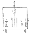
FIG. 10 shows an alternative TES generator in accordance with the
present invention. The position signal X is bandpass filtered in BPF 150. The
diffraction-based MFE signal Y is bandpass filtered in BPF 170 and phase adjusted in
phase adjust element 172. The signals X and Y are then multiplied together in a
multiplier 200 and the result is filtered in low-pass filter 180 to provide a dynamic
TES. When the signals X and Y are in phase, corresponding to a groove centerline to
the right of the recording spot, the TES will be positive in sign. When the signals X
and Y are out of phase, corresponding to a groove centerline to the left of the
recording spot, the TES will be negative in sign. The magnitude of the TES will
increase as the recording beam moves farther off-track in either direction. When the
recording beam is on-track, the TES will be substantially zero. Again, the dynamic
TES can be utilized in a conventional tracking servo control system to keep the
recording beam on-track. The dynamic TES may be used alone or in conjunction with
a push-pull signal or other conventional tracking signal.
Although not shown in FIG. 1, the recording system 10 could include a
computer, microprocessor, application-specific integrated circuit (ASIC) or other
digital data processor suitable for directing the signal processing operations described
above. The system 10 may also include a system memory capable of storing, for
example, various measured signal values. Furthermore, it should be noted that the
signal processing operations may be completely or partially implemented in software or
firmware.
It should be emphasized that the embodiments described above are
exemplary only. Many variations may be made in the arrangements shown, including,
for example, the type of diffraction-based MFE and position signals used, and the
manner in which the diffraction-based MFE and position signals are correlated to
provide a dynamic tracking error signal.
PARTS LIST
- 10
- optical recording system
- 11
- optical source
- 12
- beam-shaping optics
- 13
- beam splitter
- 14
- optical recording medium
- 15
- objective lens
- 16
- housing
- 17
- servo control system
- 18
- beam splitter
- 19
- detector array
- 20
- focus detector
- 21
- optical aperture
- 22
- focusing lens
- 23
- diffraction-based MFE signal generator
- 25
- position signal generator
- 30
- tracking error signal generator
- 50
- polycarbonate substrate
- 52
- incident recording beam
- 53
- groove
- 54
- substrate surface
- 55
- dye recording layer
- 56
- gold reflective layer
- 57
- area between grooves
- 100
- reflected write pulse
- 105
- integrated area
- 110
- reflected pulse falling edge
- 150
- band pass filter
- 152
- digitizer
Parts List cont'd
- 154
- switch
- 156
- switch
- 160
- inverter
- 170
- band pass filter
- 172
- phase adjust element
- 180
- low pass filter
- 182
- low pass filter
- 184
- difference circuit
- 200
- multiplier
- A, B, C
- beam spot positions
- CL1
- groove centerline
- D1, D2, D3, D4
- detector elements
- d1, d2, d3, d4
- detected signals
- FA
- focus actuator
- S1
- recording spot
- TA
- tracking actuator
- TS1, TS2
- tracking structures
- T0
- reflected pulse rising edge time
- ΔT
- predetermined time interval
- J
- Signal generated from a first defined zone of the return beam aperture
- K
- Signal generated from a second defined zone of the return beam
aperture
- JΔT
- Sample of signal J at predetermine time interval
- KΔT
- Sample of signal K at predetermine time interval
- X
- position signal
- ΔX
- position signal variation
- Y, YA1, YC1
- diffraction-based MFE signals
Parts List cont'd
- ΔYA, ΔYB, ΔYC
- diffraction-based MFE signal variation