EP0854360B1 - Optical fiber monitor using optical time domain reflectometer and monitoring method - Google Patents
Optical fiber monitor using optical time domain reflectometer and monitoring method Download PDFInfo
- Publication number
- EP0854360B1 EP0854360B1 EP97954851A EP97954851A EP0854360B1 EP 0854360 B1 EP0854360 B1 EP 0854360B1 EP 97954851 A EP97954851 A EP 97954851A EP 97954851 A EP97954851 A EP 97954851A EP 0854360 B1 EP0854360 B1 EP 0854360B1
- Authority
- EP
- European Patent Office
- Prior art keywords
- optical fiber
- otdr
- optical
- measurement signal
- drift amount
- Prior art date
- Legal status (The legal status is an assumption and is not a legal conclusion. Google has not performed a legal analysis and makes no representation as to the accuracy of the status listed.)
- Expired - Lifetime
Links
- 239000013307 optical fiber Substances 0.000 title claims description 258
- 230000003287 optical effect Effects 0.000 title claims description 82
- 238000012544 monitoring process Methods 0.000 title claims description 59
- 238000000034 method Methods 0.000 title claims description 29
- 238000005259 measurement Methods 0.000 claims description 65
- 230000015654 memory Effects 0.000 claims description 48
- 238000012935 Averaging Methods 0.000 claims description 9
- 230000005540 biological transmission Effects 0.000 claims description 5
- 238000000253 optical time-domain reflectometry Methods 0.000 claims 27
- 230000007547 defect Effects 0.000 description 17
- 230000005856 abnormality Effects 0.000 description 15
- 238000004891 communication Methods 0.000 description 9
- 239000000835 fiber Substances 0.000 description 8
- 238000012360 testing method Methods 0.000 description 7
- 238000012545 processing Methods 0.000 description 5
- 230000006866 deterioration Effects 0.000 description 4
- 230000003321 amplification Effects 0.000 description 3
- 238000003199 nucleic acid amplification method Methods 0.000 description 3
- 230000015556 catabolic process Effects 0.000 description 2
- 238000010276 construction Methods 0.000 description 2
- 238000006731 degradation reaction Methods 0.000 description 2
- 238000010586 diagram Methods 0.000 description 2
- 238000011161 development Methods 0.000 description 1
- 230000018109 developmental process Effects 0.000 description 1
- 230000006870 function Effects 0.000 description 1
- 238000004519 manufacturing process Methods 0.000 description 1
- 230000006386 memory function Effects 0.000 description 1
- 230000000630 rising effect Effects 0.000 description 1
Images
Classifications
-
- G—PHYSICS
- G01—MEASURING; TESTING
- G01M—TESTING STATIC OR DYNAMIC BALANCE OF MACHINES OR STRUCTURES; TESTING OF STRUCTURES OR APPARATUS, NOT OTHERWISE PROVIDED FOR
- G01M11/00—Testing of optical apparatus; Testing structures by optical methods not otherwise provided for
- G01M11/30—Testing of optical devices, constituted by fibre optics or optical waveguides
- G01M11/31—Testing of optical devices, constituted by fibre optics or optical waveguides with a light emitter and a light receiver being disposed at the same side of a fibre or waveguide end-face, e.g. reflectometers
- G01M11/3109—Reflectometers detecting the back-scattered light in the time-domain, e.g. OTDR
- G01M11/3145—Details of the optoelectronics or data analysis
Definitions
- the present invention relates generally to an optical fiber monitoring apparatus and method, and more particularly to an optical fiber monitoring apparatus and method using an optical time domain reflectometer (OTDR) which supplies a light pulse into an optical fiber for use in a communication cable, etc., receives light returning from the optical fiber, and detects a defect, etc. of the optical fiber on the basis of the received signal, thereby preventing a deterioration of the precision in detecting the defect, which deterioration occurs due to a variation in performance of the OTDR itself resulting from a change in ambience.
- OTDR optical time domain reflectometer
- the present invention relates to an optical fiber monitoring apparatus as defined in the preamble of claim 1 and an optical fiber monitoring method as defined in the pre-amble of claim 17.
- an apparatus and method are known from EP-A-0 453 816.
- An optical pulse test device called an optical time domain reflectometer (OTDR) has generally been used in the prior art to detect a defect, etc. of an optical fiber used as a communication cable, etc.
- ODR optical time domain reflectometer
- FIG. 8 shows a structure of a conventional optical time domain reflectometer (OTDR) 10 for testing the optical fiber, as described above.
- OTDR optical time domain reflectometer
- the optical time domain reflectometer (OTDR) 10 comprises a light pulse generator 11 for outputting pulse-like light, a light receiver 12, and an optical coupler 14 for guiding a light pulse output from the light pulse generator 11 to an optical fiber 1 to be tested via an optical connector 13 and also guiding to the receiver 12 the light (backward scattering light or Fresnel reflection light) returning from the optical fiber 1 toward the optical connector 13.
- an output signal from the light receiver 12 which has been obtained in a predetermined time period since the light pulse was output from the light pulse generator 11, is processed to generate a measurement signal corresponding to transmission characteristics of the optical fiber 1 in the distance direction of the fiber.
- a waveform level of the measurement signal is plotted on a time axis (a distance axis) on a monitor screen.
- the user compares the waveform displayed on the monitor screen and a waveform measured in advance when the optical fiber was laid out and thus finds a position on the optical fiber where abnormality has occurred. Thus, the defect of the optical fiber is detected and repaired.
- the user is unable to distinguish a loss increased due to only abnormality on the optical fiber side from a signal level variation on the OTDR body side due to a change in ambience, for example, a drift due to characteristics of the OTDR itself, such as a signal level variation resulting from an output variation of the pulse generator or an amplification degree variation of the light receiver. Consequently, the user may erroneously determine a defect of the optical fiber.
- the user compares the waveform displayed on the monitor screen and a waveform measured in advance when the optical fiber was laid out and thus finds a position on the optical fiber where abnormality has occurred. Thus, the defect of the optical fiber is detected.
- this optical time domain reflectometer (OTDR) alone, it is not possible to perform an automatic monitor operation aiming at detecting a defect, etc. of the optical fiber.
- the document EP-A-0 453 816 discloses an optical time domain reflector (OTDR) which comprises a reference fiber interposed between an optical coupler and a front panel connector for acquiring a reference backscatter level that is independent from a fiber under test.
- the reference level is used to determine the quality of the front panel connection between the OTDR and the fiber under test, and for verifying and adjusting a transmitter and receiver circuitry in the OTDR.
- the reference fiber also allows the acquisition of front panel connector reflection data when a Bragg cell is used as the optical coupler.
- the document EP-A-0 453 816 also discloses a method of inspecting the condition of a connection between an optical fiber to be tested and the optical time domain reflectometer (OTDR) by comparing backward scattering light data from the reference optical fiber and that from the optical fiber to be tested.
- OTDR optical time domain reflectometer
- the document EP-A-0 318 043 discloses a previous device of the applicant and comprises a light pulse testing device which measures the light loss of a fiber to be measured and detects a defect or the like. Also, that document discloses a method of automatically detecting a defect producing a loss which is higher than a predetermined value, namely by comparing a predetermined threshold value and the difference between the light receiving amount in a rising portion of a peak in the waveform data which are measured by the light pulse testing device, and the light receiving amount in a falling portion of the waveform data, wherein a peak corresponds to Fresnel reflection light occurring at a break point.
- An object of the present invention is to solve the above problems and to provide an optical fiber monitoring apparatus using an OTDR for detecting a defect, etc. of an optical fiber and being capable of exactly performing an automatic monitoring operation for an optical fiber to be monitored, even if there is a drift due to characteristics of the OTDR itself, such as a signal level variation on the OTDR body side due to a change in ambience.
- an optical fiber monitoring apparatus comprising:
- an optical fiber monitoring method comprising the following steps:
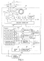
- FIG. 1 shows a structure of an optical fiber monitoring apparatus 20 according to an embodiment of the present invention.
- the optical fiber monitoring apparatus 20 cooperates with a center apparatus 42 connected thereto via a telephone line 5, thereby constituting an optical fiber monitoring system for monitoring a number of optical fibers in a centralized manner.
- the optical fiber monitoring apparatus 20 receives schedule information from the center apparatus 42 and, according to the schedule information, automatically performs monitoring and measuring of the optical fibers. Thus, the optical fiber monitoring apparatus 20 detects a breakage or a defect of the optical fibers, and sends the detected result to the center apparatus 42.
- the optical fiber monitoring apparatus 20 generally comprises an optical fiber connection change-over section 201, an OTDR section 202, a storage/arithmetic section 203, and a communication section 204.
- the optical fiber connection change-over section 201 of the optical fiber monitoring apparatus 20 is provided with three connectors 20a, 20b and 20c for connection with external optical fibers 1 to be monitored.
- the connectors 20a to 20c are connected to a one-to-four optical switch 21.
- Predetermined non-used or in-service optical fibers in optical fiber cables each comprising optical fibers laid out as communication lines are connected, as optical fibers 1 to be monitored, to the connectors 20a to 20c via optical filters (not shown).
- the optical switch 21 comprises four connection terminals 21a to 21d and one change-over terminal 21e.
- a change-over signal is supplied from a measuring control unit 30 (described later) to the optical switch 21 to optically connect one of the connection terminals 21a to 21d to the change-over terminal 21e.
- the three connection terminals 21a to 21c of the optical switch 21 are connected to the connectors 20a to 20c by means of optical fibers.
- connection terminal 21d of the optical switch 21 is connected to one end of a reference optical fiber 22 having a predetermined length (e.g. 50 m) and already known attenuation characteristics, etc.
- the other end of the reference optical fiber 22 is opened within the optical fiber monitoring apparatus 20.
- the change-over terminal 21e of the optical switch 21 is connected to an optical pulse generator 24 and a light receiver 25 via an optical coupler 23 constituting a part of the OTDR section 202.
- the optical coupler 23 outputs an optical pulse, which is output from the optical pulse generator 24, to the change-over terminal 21e of the optical switch 21 and also supplies the light, which returns to the optical coupler 23 from the change-over terminal 21e, to the light receiver 25.
- the light receiver 25 outputs a light reception signal, which corresponds to the intensity of the received light, to an analog/digital (A/D) converter 26.
- A/D analog/digital
- the A/D converter 26 converts the light reception signal output from the light receiver 25 to a digital signal and outputs the digital signal to an averaging circuit 27.
- the averaging circuit 26 averages a series of light reception signal data which is obtained at each time, based on the predetermined number of times, and outputs the averaged result to the measuring control unit 30.
- a series of light reception signal data which is output from the A/D converter 26 during a time period from the output timing of the first optical pulse to the end of a predetermined time, is stored in an internal memory (not shown) in the order of addresses.
- light reception signal data associated with the second optical pulse is added to the previous light reception signal data stored in the internal memory.
- the averaging circuit 27 completes a predetermined number of times of this operation, the data accumulated in the internal memory is averaged by dividing the data by a value corresponding to the predetermined number of times.
- the averaged light reception data is output to the measuring control unit 30 as a result of measurement of the optical fiber by the OTDR.
- the measuring control unit 30 controls, according to schedule information delivered from the center apparatus 42, the optical switch 21, the optical pulse generator 24, the A/D converter 26 and the averaging circuit 27.
- the measuring control unit 30 enables the OTDR section 202 to perform, for example, periodically, the measurement of the reference optical fiber 22 and the to-be-monitored optical fibers 1 connected to the respective connection terminals of the optical switch 21.
- the measuring control unit 30 enables the memory 31 to store the light reception signal data averaged by the averaging circuit 27 in association with the respective connection terminals.
- the measuring control unit 30 may, according to an operational instruction from an operation unit (not shown), enable the OTDR section 202 to perform the measurement of the reference optical fiber 22 and a chosen to-be-monitored optical fiber 1 and enable the memory 31 to store the measured result as initial data.
- the measuring control unit 30 may be built in the optical fiber monitoring apparatus 20 as a microprocessor (CPU) or may be replaced with a personal computer (PC) connected outside the optical fiber monitoring apparatus 20.
- CPU microprocessor
- PC personal computer
- the measuring control unit 30 may execute the above-described control functions with use of software.
- the memory 31 comprises a first initial data memory 31a for prestoring, as initial data, light reception signal data of the reference optical fiber 22, which was initially measured at the time of the manufacture of the optical fiber monitoring apparatus according to the present embodiment; second to fourth initial data memories 31b to 31d for storing, as initial data, light reception signal data of the to-be-monitored fibers 1, which were initially measured at the time of connection of the to-be-measured optical fibers 1; a first measured data memory 31e for storing light reception signal data of the reference optical fiber 22 which is newly measured for the purpose of monitoring; and a second measured data memory 31f for storing light reception signal data of the to-be-monitored optical fibers 1 which are newly measured for the purpose of monitoring.
- a determination unit 32 connected to the memory 31 comprises a first arithmetic unit 33, a second arithmetic unit 34, a third arithmetic unit 35 and a waveform comparator 36.
- the determination unit 32 determines the presence/absence of breakage or deterioration of each to-be-monitored optical fiber 1 based on the light reception signal data stored in the memories 31a to 31f of the memory 31.
- the first arithmetic unit 33 finds as a drift amount ⁇ a level difference between the light reception signal data stored in the first measured data memory 31e and the initial data stored in the first initial data memory 31a
- the level difference representing the drift amount ⁇ is a difference between those data items among the data stored in both memories 31a and 31e, which have the same address corresponding to the position where the influence of connector reflection of the reference optical fiber 22 is small.
- the drift amount ⁇ is considered to occur mainly due to variations in characteristics of the inside of the OTDR section 202, for example, a level variation in output light from the optical pulse generator 24, a variation in amplification degree of the light receiver 25, and degradation by loss at the input side including the optical switch 21.
- the drift amount ⁇ is substantially defined to be a first drift amount representing a variation in characteristics of the inside of the OTDR section 202.
- the second arithmetic unit 34 finds a level difference ⁇ between the light reception signal data of the to-be-monitored optical fiber 1, which was measured for the purpose of monitoring and stored in the second measured data memory 31f, and the initial data corresponding to the to-be-monitored optical fiber 1 among the initial data stored in the second to fourth initial data memories 31b to 31d.
- This level difference is a difference between data items at the same address corresponding to the position where there is no influence of connector reflection of the to-be-monitored optical fiber 1.
- the level difference ⁇ and the above-mentioned drift amount ⁇ are not limited to a level difference of a specific address value, but may be an average value of level differences of a plurality of address values.
- the level difference ⁇ is substantially defined to be a second drift amount representing a variation in characteristics of the inside of the OTDR section 202 and characteristics of the to-be-monitored optical fiber 1.
- the third arithmetic unit 35 subtracts the drift amount ⁇ found by the first arithmetic unit 33 from the level difference ⁇ found by the second arithmetic unit 34 and outputs the subtracted result as a real level difference ⁇ .
- the real level difference ⁇ is substantially defined to be a third drift amount representing a variation in characteristics of the to-be-monitored optical fiber 1.
- the waveform comparator 36 performs waveform comparison between the light reception signal data of the to-be-monitored optical fiber 1, which was measured for the purpose of monitoring and stored in the second measured data memory 31f, and the initial data of the to-be-monitored optical fiber 1 which is stored in any one of the second to fourth initial data memories 31b to 31d, based on the real level difference ⁇ obtained by the third arithmetic unit 35, i.e. the third drift amount representing the variation in characteristics of the to-be-monitored optical fiber 1.
- the waveform comparator 36 thus detects the presence/absence of an abnormality of the to-be-monitored optical fiber 1.
- the waveform comparator 36 detects the presence/absence of an abnormality of the to-be-monitored optical fiber 1 by finding, as difference data at each address, a difference between the light reception signal data of the to-be-monitored optical fiber 1, which is stored in the second measured data memory 31f, and the initial data of the to-be-monitored optical fiber 1, and determining whether this difference data falls outside an allowable range ⁇ ⁇ L set for the real level difference ⁇ , i.e. the third drift amount representing the variation in characteristics of the to-be-monitored optical fiber 1.
- the waveform comparator 36 finds the address position of the difference data and finds the position of the defect of the to-be-monitored optical fiber 1 from this address position.
- a communication control unit 40 which is a part of the communication section 204, delivers the determination result of the determination unit 32 to the center apparatus 42 via a MODEM unit 41, and also sets the schedule information sent from the center apparatus 42 in the measuring control unit 30.
- the center apparatus 42 is connected to a plurality of optical fiber monitoring apparatuses 20 over telephone lines, and receives abnormality position information, etc. of to-be-monitored optical fibers 1 from the optical fiber monitoring apparatuses 20. Thus, the center apparatus 42 instructs repairing processes to proper organizations.
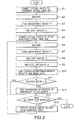
- FIG. 2 is a flow chart illustrating an example of the processing procedure of the optical fiber monitoring apparatus 20 and monitoring method.
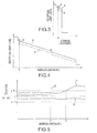
- the first initial data memory 31a prestores initial data of the reference optical fiber 22, as indicated by R in FIG. 3.
- the second initial data memory 31b for example, of the second to fourth initial data memories 31b to 31d prestores initial data of the to-be-monitored optical fiber 1, as indicated by P in FIG. 4.
- the optical switch 21 is connected to the reference optical fiber 22.
- the OTDR section 202 performs measurement of the reference optical fiber 22 (steps S1 and S2).
- the light reception signal data R' is stored in the first measured data memory 31e (step S3).
- a difference between the reception light signal data R' at a specific address position A and the initial data R at address position A stored in the first initial data memory 31a is calculated by the first arithmetic unit 33 as a drift amount ⁇ , i.e. the first drift amount representing a variation in characteristics of the inside of the OTDR section 202 (step S4).
- the drift amount ⁇ can be considered to occur mainly due to variations in characteristics of the inside of the OTDR section 202, for example, a level variation in output light from the optical pulse generator 24, a variation in amplification degree of the light receiver 25, and degradation by loss at the input side including the optical switch 21.
- the optical switch 21 is then connected to the connection terminal 20a, and the OTDR section 202 performs measurement of the to-be-monitored optical fiber 1 connected to the connection terminal 20a (steps S5 and S6).
- the light reception signal data P' is stored in the second measured data memory 31b (step S7).
- a difference between the reception light signal data R' at a specific address position B and the initial data R at address position B stored in the first initial data memory 31a is calculated by the second arithmetic unit 34 as a level difference ⁇ , i.e. the second drift amount representing a variation in characteristics of the inside of the OTDR section 202 itself and characteristics of the to-be-monitored optical fiber 1 (step S8).
- the third arithmetic unit 35 subtracts the first drift amount ( ⁇ ) representing the variation in characteristics of the OTDR 202 itself from the level difference ( ⁇ ), i. e. the second drift amount ( ⁇ ) representing the variation in characteristics of the OTDR section 202 itself and characteristics of the to-be-monitored optical fiber 1.
- the third arithmetic unit 35 calculates a real level difference ⁇ representing a variation in characteristics of the to-be-monitored optical fiber 1, i.e.
- the waveform comparator 36 finds, as difference data, a difference at each address between the light reception signal data P' and the initial data P in the second initial data memory 31b and determines whether this difference data falls outside an allowable range ⁇ ⁇ L set for the third drift amount ( ⁇ ) representing the variation in characteristics of the to-be-monitored optical fiber 1 (steps S10 and S11).
- the information on the position of the defect in the to-be-monitored optical fiber 1 is obtained and the obtained information is sent to the center apparatus 42 via the communication control unit 40 and MODEM unit 41 (step S12).
- steps S1 to S14 are repeated, if necessary.
- the above-described processing procedure is based on the schedule information from the center apparatus 42.
- the processing procedure is not limited to this.
- the reference optical fiber 22 After the reference optical fiber 22 has been measured, all the to-be-monitored optical fibers 1 are measured and the measured data is stored. Then, an abnormality may be determined.
- the measurement of the reference optical fiber 22 may be conducted, for example, once per day. Based on the first drift amount ( ⁇ ) obtained by the measurement, the second drift amount ( ⁇ ) and third drift amount ( ⁇ ) are found. These amounts are used for the determination the occurrence of defects in to-be-monitored optical fibers 1 which is to be performed in the same day.
- the presence/absence of an abnormality of the to-be-monitored optical fiber 1 is determined based on the third drift amount ( ⁇ ) representing the variation in characteristics of the to-be-monitored optical fiber 1, which is obtained by subtracting the first drift amount ( ⁇ ) representing the variation in characteristics of the OTDR 202 itself, which is obtained by measuring the reference optical fiber 22, from the second drift amount ( ⁇ ) representing the variation in characteristics of the OTDR section 202 itself and characteristics of the to-be-monitored optical fiber 1.
- the optical fiber monitoring apparatus can exactly monitor the to-be-monitored optical fiber 1, without erroneously determining abnormality of the to-be-monitored optical fiber 1 even if there is a drift of signal level variation, etc. due to the internal characteristics of the OTDR section resulting from an ambient change, etc.
- the optical fiber monitoring apparatus performs the measurement of the reference optical fiber 22 and to-be-monitored optical fibers 1 and the determination of an abnormality according to the schedule information from the center apparatus 42. Then, the result is sent to the center apparatus 42.
- the present invention is not limited to this structure.
- the present invention can be applied to an optical fiber monitoring apparatus including an OTDR which can be singly used and includes an operation section for setting measurement conditions, etc. and a display for displaying a measurement result and determination result.
- an optical fiber monitoring apparatus including an OTDR which can be singly used and includes an operation section for setting measurement conditions, etc. and a display for displaying a measurement result and determination result.
- the reference optical fiber 22 is provided separately from the to-be-monitored optical fibers 1, and the measurement for the reference optical fiber 22 and the measurement for the to-be-monitored optical fibers 1 are performed at different timings.
- the invention is not limited to this structure.
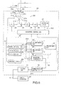
- reference optical fibers 22a to 22c are connected in series to to-be-monitored optical fibers 1, and the measurement for the reference optical fibers 22a to 22c and that for the to-be-monitored optical fibers 1 are performed at the same timing.
- connection terminals 21a to 21c of the optical switch 21 and the connectors 20a to 20c are connected by means of the reference optical fibers 22a to 22c each having a predetermined length (e.g. 50 m).
- First to third initial data memories 45a, 45b and 45c of the memory 31' store, as initial data, data Qa, Qb and Qc which are initially measured in the state in which the to-be-monitored optical fibers 1 are connected to the connectors 20a to 20c.
- the parts common to those of the optical fiber monitoring apparatus 20 according to the embodiment shown in FIG. 1 are denoted by like reference numerals with dash ('), and a description thereof is omitted.
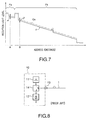
- the optical switch 21 was connected to, for example, the connection terminal 21a to measure the to-be-monitored optical fiber 1, and light reception signal data F as shown in FIG. 7 was stored in a measured data memory 45d.
- the first arithmetic unit 33' finds a level difference at an address A between the light reception signal data F and the initial data Qa stored in the initial data memory 45a, i.e. a level difference of measured data portion Fa due to reflection of the reference optical fiber 22a as shown in FIG. 7, as a drift amount ⁇ , i.e. a first drift amount representing a variation in characteristics of the OTDR section 202 itself.
- the second arithmetic unit 34' finds a level difference at an address B between the light reception data F and the initial data Qa stored in the initial data memory 45a, i.e. a level difference ⁇ of measured data portion Fb due to reflection of the to-be-monitored optical fiber 1 connected to the connector 20a as shown in FIG. 7, which is a second drift amount representing a variation in characteristics of the OTDR section 202 itself and characteristics of the to-be-monitored optical fiber 1.
- the third arithmetic unit 35' finds a real level variation amount ⁇ representing a variation in characteristics of the to-be-monitored optical fiber 1 by subtracting the drift amount ⁇ from the level difference ⁇ , that is, a third drift amount representing a variation in characteristics of the to-be-monitored optical fiber 1 which is obtained by subtracting the first drift amount representing the variation in characteristics of the OTDR section 202 itself from the second drift amount representing a variation in characteristics of the OTDR section 202 itself and characteristics of the to-be-monitored optical fiber 1.
- the waveform comparator 36' determines whether deviation data between the light reception signal data F and the initial data Qa in the initial data memory 45a in the measured data portion Fb due to reflection of the to-be-monitored optical fiber 1 falls outside an allowable range ⁇ ⁇ L set for the real variation amount ⁇ due to the variation in characteristics of to-be-monitored optical fiber 1, i.e. the second drift amount ⁇ representing the variation in characteristics of the OTDR section 202 itself and characteristics of the to-be-monitored optical fiber 1.
- the waveform comparator 36' determines the presence/absence of an abnormality of the to-be-monitored optical fiber 1 and sends the determination result to the center apparatus 42 via the communication section 204, like the optical fiber monitoring apparatus 20 according to the embodiment shown in FIG. 1.
- the optical switch 21 can be connected to the to-be-monitored fibers 1 and there is no need to use the optical switch 21 in the case where the number of to-be-monitored optical fibers 1 is one.
- the optical fiber monitoring apparatus 20' of the other embodiment shown in FIG. 6 no time is required to measure the reference optical fibers 22a to 22c independently. Even if the number of to-be-monitored optical fibers 1 is large, the to-be-monitored optical fibers 1 can be efficiently measured.
- memories 31a to 31f, 45a to 45d are independently provided within the memory 31, 31'.
- this invention is not limited to this structure. If memory functions are provided, where necessary, in the arithmetic units 33 to 36, 33' to 36' in the determination unit 32, 32', some of the memories 31a to 31f, 45a to 45d may be dispensed with.
- a reference optical fiber having a predetermined length is provided and the OTDR device finds, as a drift amount of the OTDR device itself, a difference between a signal obtained by previously measuring the reference optical fiber and a signal newly obtained.
- the OTDR device corrects, based on this drift amount, a difference between a signal obtained by previously measuring a to-be-monitored optical fiber and a signal obtained by newly measuring it. Based on the corrected signal, the presence/absence of an abnormality of the to-be-monitored optical fiber is detected.
- the optical fiber monitoring apparatus and method when the presence/absence of an abnormality of the to-be-monitored optical fiber is to be detected by using the OTDR device, the abnormality of the to-be-monitored optical fiber is not erroneously detected even if there is a signal level variation on the OTDR device side due to an ambient change, etc.
- the to-be-monitored optical fiber can be exactly monitored.
- the present invention can solve the problems of the prior art and can provide an optical fiber monitoring apparatus and method using an OTDR for detecting a defect, etc. of an optical fiber and being capable of exactly performing an automatic monitoring operation for an optical fiber to be monitored, even if there is a drift due to characteristics of the OTDR itself, such as a signal level variation on the OTDR body side due to a change in ambience.
Description
- The present invention relates generally to an optical fiber monitoring apparatus and method, and more particularly to an optical fiber monitoring apparatus and method using an optical time domain reflectometer (OTDR) which supplies a light pulse into an optical fiber for use in a communication cable, etc., receives light returning from the optical fiber, and detects a defect, etc. of the optical fiber on the basis of the received signal, thereby preventing a deterioration of the precision in detecting the defect, which deterioration occurs due to a variation in performance of the OTDR itself resulting from a change in ambience.
- In particular, the present invention relates to an optical fiber monitoring apparatus as defined in the preamble of
claim 1 and an optical fiber monitoring method as defined in the pre-amble of claim 17. Such an apparatus and method are known from EP-A-0 453 816. - An optical pulse test device called an optical time domain reflectometer (OTDR) has generally been used in the prior art to detect a defect, etc. of an optical fiber used as a communication cable, etc.
- FIG. 8 shows a structure of a conventional optical time domain reflectometer (OTDR) 10 for testing the optical fiber, as described above.
- The optical time domain reflectometer (OTDR) 10 comprises a
light pulse generator 11 for outputting pulse-like light, alight receiver 12, and anoptical coupler 14 for guiding a light pulse output from thelight pulse generator 11 to anoptical fiber 1 to be tested via anoptical connector 13 and also guiding to thereceiver 12 the light (backward scattering light or Fresnel reflection light) returning from theoptical fiber 1 toward theoptical connector 13. - In the optical time domain reflectometer (OTDR) 10, an output signal from the
light receiver 12, which has been obtained in a predetermined time period since the light pulse was output from thelight pulse generator 11, is processed to generate a measurement signal corresponding to transmission characteristics of theoptical fiber 1 in the distance direction of the fiber. A waveform level of the measurement signal is plotted on a time axis (a distance axis) on a monitor screen. - The user compares the waveform displayed on the monitor screen and a waveform measured in advance when the optical fiber was laid out and thus finds a position on the optical fiber where abnormality has occurred. Thus, the defect of the optical fiber is detected and repaired.
- In the above-described conventional optical time domain reflectometer (OTDR) 10, however, the user is unable to distinguish a loss increased due to only abnormality on the optical fiber side from a signal level variation on the OTDR body side due to a change in ambience, for example, a drift due to characteristics of the OTDR itself, such as a signal level variation resulting from an output variation of the pulse generator or an amplification degree variation of the light receiver. Consequently, the user may erroneously determine a defect of the optical fiber.
- Besides, in the above-described optical time domain reflectometer (OTDR), the user compares the waveform displayed on the monitor screen and a waveform measured in advance when the optical fiber was laid out and thus finds a position on the optical fiber where abnormality has occurred. Thus, the defect of the optical fiber is detected. With this optical time domain reflectometer (OTDR) alone, it is not possible to perform an automatic monitor operation aiming at detecting a defect, etc. of the optical fiber.
- The document EP-A-0 453 816 discloses an optical time domain reflector (OTDR) which comprises a reference fiber interposed between an optical coupler and a front panel connector for acquiring a reference backscatter level that is independent from a fiber under test. In that conventional device, the reference level is used to determine the quality of the front panel connection between the OTDR and the fiber under test, and for verifying and adjusting a transmitter and receiver circuitry in the OTDR. The reference fiber also allows the acquisition of front panel connector reflection data when a Bragg cell is used as the optical coupler.
- The document EP-A-0 453 816 also discloses a method of inspecting the condition of a connection between an optical fiber to be tested and the optical time domain reflectometer (OTDR) by comparing backward scattering light data from the reference optical fiber and that from the optical fiber to be tested.
- The document EP-A-0 318 043 discloses a previous device of the applicant and comprises a light pulse testing device which measures the light loss of a fiber to be measured and detects a defect or the like. Also, that document discloses a method of automatically detecting a defect producing a loss which is higher than a predetermined value, namely by comparing a predetermined threshold value and the difference between the light receiving amount in a rising portion of a peak in the waveform data which are measured by the light pulse testing device, and the light receiving amount in a falling portion of the waveform data, wherein a peak corresponds to Fresnel reflection light occurring at a break point.
- An object of the present invention is to solve the above problems and to provide an optical fiber monitoring apparatus using an OTDR for detecting a defect, etc. of an optical fiber and being capable of exactly performing an automatic monitoring operation for an optical fiber to be monitored, even if there is a drift due to characteristics of the OTDR itself, such as a signal level variation on the OTDR body side due to a change in ambience.
- According to the present invention, there is provided an optical fiber monitoring apparatus comprising:
- an optical time domain reflectometer (OTDR) for delivering an optical pulse to an optical fiber and outputting a measurement signal corresponding to transmission characteristics of the optical fiber in a distance direction, based on a light reception output of return light from the optical fiber;
- arithmetic means for finding in advance a drift amount due to a variation in characteristics of the optical fiber, which is included in the measurement signal output from the OTDR; and
- determination means for determining whether a difference between an initial measurement signal of the optical fiber measured by the OTDR and an actual measurement signal of the optical fiber falls within a predetermined allowable range with reference to the drift amount found by the arithmetic means, and is characterized in that the arithmetic means include:
- first arithmetic means for finding a first drift amount due to a variation in characteristics of the OTDR itself included in the measurement signal output in advance from the OTDR;
- second arithmetic means for finding a second drift amount due to a variation in characteristics of the OTDR itself included in the measurement signal output in advance from the OTDR and a variation in characteristics of the optical fiber; and
- third arithmetic means for finding a third drift amount as the drift amount found by the arithmetic means due to a variation in characteristics of the optical fiber based on the first and second drift amounts found by the first and second arithmetic means.
- Further developments of the optical fiber monitoring apparatus according to the invention are defined in the sub-claims.
- According to the invention, there is also provided an optical fiber monitoring method comprising the following steps:
- delivering optical pulses to an optical fiber and outputting a measurement signal corresponding to transmission characteristics of the optical fiber in a distance direction, based on a light reception output of return light from the optical fiber, by using an optical time domain reflectometer (OTDR);
- finding in advance a drift amount due to a variation in characteristics of the optical fiber, which is included in the measurement signal output from the OTDR; and
- determining as to whether a difference between an initial measurement signal of the optical fiber measured by the OTDR and an actual measurement signal of the optical fiber falls within a predetermined allowable range with reference to the drift amount found by the finding step,
- first finding a first drift amount due to a variation in characteristics of the OTDR itself included in the measurement signal output in advance from the OTDR,
- second finding a second drift amount due to a variation in characteristics of the OTDR itself included in the measurement signal output in advance from the OTDR and a variation in characteristics of the optical fiber, and
- third finding a third drift amount as the drift amount found by the finding due to a variation in characteristics of the optical fiber based on the first and second drift amounts found by the first and second finding steps.
-
- FIG. 1 is a block diagram showing a construction of an embodiment of an optical fiber monitoring apparatus and method according to the present invention;
- FIG. 2 is a flow chart illustrating a processing procedure of the optical fiber monitoring apparatus and method according to the embodiment of the invention;
- FIG. 3 shows an example of a measured result of a reference optical fiber, which was obtained by the optical fiber monitoring apparatus and method according to the embodiment of the invention;
- FIG. 4 shows an example of a measured result of an optical fiber to be monitored, which was obtained by the optical fiber monitoring apparatus and method according to the embodiment of the invention;
- FIG. 5 shows an example of deviation data obtained by the optical fiber monitoring apparatus and method according to the embodiment of the invention;
- FIG. 6 is a block diagram showing a construction of another embodiment of an optical fiber monitoring apparatus and method according to the present invention;
- FIG. 7 shows an example of a measured result according to the embodiment of the invention as shown in FIG. 6; and
- FIG. 8 shows a structure of a conventional optical time domain reflectometer apparatus (OTDR).
- An embodiment of an optical fiber monitoring apparatus and method according to the present invention will now be described with reference to the accompanying drawings.
- FIG. 1 shows a structure of an optical
fiber monitoring apparatus 20 according to an embodiment of the present invention. - The optical
fiber monitoring apparatus 20 cooperates with acenter apparatus 42 connected thereto via atelephone line 5, thereby constituting an optical fiber monitoring system for monitoring a number of optical fibers in a centralized manner. - The optical
fiber monitoring apparatus 20 receives schedule information from thecenter apparatus 42 and, according to the schedule information, automatically performs monitoring and measuring of the optical fibers. Thus, the opticalfiber monitoring apparatus 20 detects a breakage or a defect of the optical fibers, and sends the detected result to thecenter apparatus 42. - The optical
fiber monitoring apparatus 20 generally comprises an optical fiber connection change-oversection 201, anOTDR section 202, a storage/arithmetic section 203, and acommunication section 204. - The optical fiber connection change-over
section 201 of the opticalfiber monitoring apparatus 20 is provided with threeconnectors optical fibers 1 to be monitored. - The
connectors 20a to 20c are connected to a one-to-fouroptical switch 21. - Predetermined non-used or in-service optical fibers in optical fiber cables each comprising optical fibers laid out as communication lines are connected, as
optical fibers 1 to be monitored, to theconnectors 20a to 20c via optical filters (not shown). - The technique for connecting in-service optical fibers as to-be-monitored
optical fibers 1 with use of optical filters is described in detail in "In-service Optical Line Characteristics Testing Method Using Optical Pulse Tester", Papers of the Institute of Electronics, Information and Communications Engineering, B-1, Vol. J75-B-1, No. 3, pp. 311-320. - The
optical switch 21 comprises fourconnection terminals 21a to 21d and one change-overterminal 21e. A change-over signal is supplied from a measuring control unit 30 (described later) to theoptical switch 21 to optically connect one of theconnection terminals 21a to 21d to the change-overterminal 21e. The threeconnection terminals 21a to 21c of theoptical switch 21 are connected to theconnectors 20a to 20c by means of optical fibers. - The
connection terminal 21d of theoptical switch 21 is connected to one end of a referenceoptical fiber 22 having a predetermined length (e.g. 50 m) and already known attenuation characteristics, etc. The other end of the referenceoptical fiber 22 is opened within the opticalfiber monitoring apparatus 20. - The change-over terminal 21e of the
optical switch 21 is connected to anoptical pulse generator 24 and alight receiver 25 via anoptical coupler 23 constituting a part of theOTDR section 202. - The
optical coupler 23 outputs an optical pulse, which is output from theoptical pulse generator 24, to the change-over terminal 21e of theoptical switch 21 and also supplies the light, which returns to theoptical coupler 23 from the change-over terminal 21e, to thelight receiver 25. - The
light receiver 25 outputs a light reception signal, which corresponds to the intensity of the received light, to an analog/digital (A/D)converter 26. - The A/
D converter 26 converts the light reception signal output from thelight receiver 25 to a digital signal and outputs the digital signal to an averagingcircuit 27. - When an optical pulse is output by a predetermined number of times (e.g. 10 times) to one optical fiber connected to the
optical switch 21, the averagingcircuit 26 averages a series of light reception signal data which is obtained at each time, based on the predetermined number of times, and outputs the averaged result to the measuringcontrol unit 30. - Specifically, in the averaging
circuit 27, a series of light reception signal data, which is output from the A/D converter 26 during a time period from the output timing of the first optical pulse to the end of a predetermined time, is stored in an internal memory (not shown) in the order of addresses. In addition, light reception signal data associated with the second optical pulse is added to the previous light reception signal data stored in the internal memory. - If the averaging
circuit 27 completes a predetermined number of times of this operation, the data accumulated in the internal memory is averaged by dividing the data by a value corresponding to the predetermined number of times. The averaged light reception data is output to the measuringcontrol unit 30 as a result of measurement of the optical fiber by the OTDR. - The measuring
control unit 30, along with a memory 31 (described later) of the storage/arithmetic section 203, constitutes first to fourth memory means according to this embodiment. - Specifically, the measuring
control unit 30 controls, according to schedule information delivered from thecenter apparatus 42, theoptical switch 21, theoptical pulse generator 24, the A/D converter 26 and the averagingcircuit 27. Thereby, the measuringcontrol unit 30 enables theOTDR section 202 to perform, for example, periodically, the measurement of the referenceoptical fiber 22 and the to-be-monitoredoptical fibers 1 connected to the respective connection terminals of theoptical switch 21. In addition, the measuringcontrol unit 30 enables thememory 31 to store the light reception signal data averaged by the averagingcircuit 27 in association with the respective connection terminals. - The measuring
control unit 30 may, according to an operational instruction from an operation unit (not shown), enable theOTDR section 202 to perform the measurement of the referenceoptical fiber 22 and a chosen to-be-monitoredoptical fiber 1 and enable thememory 31 to store the measured result as initial data. - Moreover, the measuring
control unit 30 may be built in the opticalfiber monitoring apparatus 20 as a microprocessor (CPU) or may be replaced with a personal computer (PC) connected outside the opticalfiber monitoring apparatus 20. - In other words, the measuring
control unit 30 may execute the above-described control functions with use of software. - The
memory 31 comprises a firstinitial data memory 31a for prestoring, as initial data, light reception signal data of the referenceoptical fiber 22, which was initially measured at the time of the manufacture of the optical fiber monitoring apparatus according to the present embodiment; second to fourthinitial data memories 31b to 31d for storing, as initial data, light reception signal data of the to-be-monitored fibers 1, which were initially measured at the time of connection of the to-be-measuredoptical fibers 1; a first measureddata memory 31e for storing light reception signal data of the referenceoptical fiber 22 which is newly measured for the purpose of monitoring; and a second measureddata memory 31f for storing light reception signal data of the to-be-monitoredoptical fibers 1 which are newly measured for the purpose of monitoring. - A
determination unit 32 connected to thememory 31 comprises a firstarithmetic unit 33, a secondarithmetic unit 34, a thirdarithmetic unit 35 and awaveform comparator 36. - The
determination unit 32 determines the presence/absence of breakage or deterioration of each to-be-monitoredoptical fiber 1 based on the light reception signal data stored in thememories 31a to 31f of thememory 31. - The first
arithmetic unit 33 finds as a drift amount α a level difference between the light reception signal data stored in the first measureddata memory 31e and the initial data stored in the firstinitial data memory 31a - The level difference representing the drift amount α is a difference between those data items among the data stored in both
memories optical fiber 22 is small. - The drift amount α, as described later, is considered to occur mainly due to variations in characteristics of the inside of the
OTDR section 202, for example, a level variation in output light from theoptical pulse generator 24, a variation in amplification degree of thelight receiver 25, and degradation by loss at the input side including theoptical switch 21. - Thus, the drift amount α is substantially defined to be a first drift amount representing a variation in characteristics of the inside of the
OTDR section 202. - The second
arithmetic unit 34 finds a level difference β between the light reception signal data of the to-be-monitoredoptical fiber 1, which was measured for the purpose of monitoring and stored in the second measureddata memory 31f, and the initial data corresponding to the to-be-monitoredoptical fiber 1 among the initial data stored in the second to fourthinitial data memories 31b to 31d. - This level difference is a difference between data items at the same address corresponding to the position where there is no influence of connector reflection of the to-be-monitored
optical fiber 1. - The level difference β and the above-mentioned drift amount α are not limited to a level difference of a specific address value, but may be an average value of level differences of a plurality of address values.
- The level difference β is substantially defined to be a second drift amount representing a variation in characteristics of the inside of the
OTDR section 202 and characteristics of the to-be-monitoredoptical fiber 1. - The third
arithmetic unit 35 subtracts the drift amount α found by the firstarithmetic unit 33 from the level difference β found by the secondarithmetic unit 34 and outputs the subtracted result as a real level difference γ. - The real level difference γ is substantially defined to be a third drift amount representing a variation in characteristics of the to-be-monitored
optical fiber 1. - The
waveform comparator 36 performs waveform comparison between the light reception signal data of the to-be-monitoredoptical fiber 1, which was measured for the purpose of monitoring and stored in the second measureddata memory 31f, and the initial data of the to-be-monitoredoptical fiber 1 which is stored in any one of the second to fourthinitial data memories 31b to 31d, based on the real level difference γ obtained by the thirdarithmetic unit 35, i.e. the third drift amount representing the variation in characteristics of the to-be-monitoredoptical fiber 1. Thewaveform comparator 36 thus detects the presence/absence of an abnormality of the to-be-monitoredoptical fiber 1. - Specifically, the
waveform comparator 36 detects the presence/absence of an abnormality of the to-be-monitoredoptical fiber 1 by finding, as difference data at each address, a difference between the light reception signal data of the to-be-monitoredoptical fiber 1, which is stored in the second measureddata memory 31f, and the initial data of the to-be-monitoredoptical fiber 1, and determining whether this difference data falls outside an allowable range γ ± L set for the real level difference γ, i.e. the third drift amount representing the variation in characteristics of the to-be-monitoredoptical fiber 1. - When this difference data falls outside the allowable range γ ± L set for the real level difference γ, i.e. the third drift amount representing the variation in characteristics of the to-be-monitored
optical fiber 1, thewaveform comparator 36 finds the address position of the difference data and finds the position of the defect of the to-be-monitoredoptical fiber 1 from this address position. - On the other hand, a
communication control unit 40, which is a part of thecommunication section 204, delivers the determination result of thedetermination unit 32 to thecenter apparatus 42 via aMODEM unit 41, and also sets the schedule information sent from thecenter apparatus 42 in the measuringcontrol unit 30. - The
center apparatus 42 is connected to a plurality of opticalfiber monitoring apparatuses 20 over telephone lines, and receives abnormality position information, etc. of to-be-monitoredoptical fibers 1 from the opticalfiber monitoring apparatuses 20. Thus, thecenter apparatus 42 instructs repairing processes to proper organizations. - FIG. 2 is a flow chart illustrating an example of the processing procedure of the optical
fiber monitoring apparatus 20 and monitoring method. - With reference to this flow chart, the operation of the optical
fiber monitoring apparatus 20 and monitoring method will now be described according to the processing procedure. - Suppose that the first
initial data memory 31a prestores initial data of the referenceoptical fiber 22, as indicated by R in FIG. 3. - In addition, suppose that the second
initial data memory 31b, for example, of the second to fourthinitial data memories 31b to 31d prestores initial data of the to-be-monitoredoptical fiber 1, as indicated by P in FIG. 4. - At first, the
optical switch 21 is connected to the referenceoptical fiber 22. Thus, theOTDR section 202 performs measurement of the reference optical fiber 22 (steps S1 and S2). - If light reception signal data, as indicated by R' in FIG. 3, is obtained by the measurement, the light reception signal data R' is stored in the first measured
data memory 31e (step S3). - Then, a difference between the reception light signal data R' at a specific address position A and the initial data R at address position A stored in the first
initial data memory 31a is calculated by the firstarithmetic unit 33 as a drift amount α , i.e. the first drift amount representing a variation in characteristics of the inside of the OTDR section 202 (step S4). - Since a time-basis variation of characteristics of the reference
optical fiber 22 disposed within the apparatus is ignorably small, the drift amount α can be considered to occur mainly due to variations in characteristics of the inside of theOTDR section 202, for example, a level variation in output light from theoptical pulse generator 24, a variation in amplification degree of thelight receiver 25, and degradation by loss at the input side including theoptical switch 21. - It is considered that the influence of the first drift amount (α) due to the characteristics of the
OTDR section 202 itself is included in the measured result of each to-be-monitoredoptical fiber 1. - The
optical switch 21 is then connected to theconnection terminal 20a, and theOTDR section 202 performs measurement of the to-be-monitoredoptical fiber 1 connected to theconnection terminal 20a (steps S5 and S6). - If light reception signal data, as indicated by P' in FIG. 4, is obtained by the measurement, the light reception signal data P' is stored in the second measured
data memory 31b (step S7). - Then, a difference between the reception light signal data R' at a specific address position B and the initial data R at address position B stored in the first
initial data memory 31a is calculated by the secondarithmetic unit 34 as a level difference β, i.e. the second drift amount representing a variation in characteristics of the inside of theOTDR section 202 itself and characteristics of the to-be-monitored optical fiber 1 (step S8). - The third
arithmetic unit 35 subtracts the first drift amount (α) representing the variation in characteristics of theOTDR 202 itself from the level difference (β), i. e. the second drift amount (β) representing the variation in characteristics of theOTDR section 202 itself and characteristics of the to-be-monitoredoptical fiber 1. Thus, the thirdarithmetic unit 35 calculates a real level difference γ representing a variation in characteristics of the to-be-monitoredoptical fiber 1, i.e. the third drift amount (γ) representing the variation in characteristics of the to-be-monitoredoptical fiber 1, which is obtained by subtracting the first drift amount (α) representing the variation in characteristics of theOTDR 202 itself from the second drift amount (β) representing the variation in characteristics of theOTDR section 202 itself and characteristics of the to-be-monitored optical fiber 1 (step S9). - The
waveform comparator 36 finds, as difference data, a difference at each address between the light reception signal data P' and the initial data P in the secondinitial data memory 31b and determines whether this difference data falls outside an allowable range γ ± L set for the third drift amount (γ) representing the variation in characteristics of the to-be-monitored optical fiber 1 (steps S10 and S11). - For example, if the difference data between the light reception signal data P' and initial data P is within the allowable range γ ± L, as indicated by D in FIG. 5, it is determined that there is no defect in the to-be-monitored
optical fiber 1. - If the difference data between the light reception signal data P' and initial data P sharply falls outside the allowable range γ ± L at an address C, as indicated by D' in FIG. 5, it is determined that there is a breakage in the to-be-monitored
optical fiber 1 at the position corresponding to the address C. - If the difference data between the light reception signal data P' and initial data P varies gently and falls outside the allowable range γ ± L at an address C', as indicated by D'' in FIG. 5, it is determined that there is a deterioration in the to-be-monitored
optical fiber 1 near the position corresponding to the address C'. - When the occurrence of the defect in the to-be-monitored
optical fiber 1 has thus been detected by thewaveform comparator 36, the information on the position of the defect in the to-be-monitoredoptical fiber 1 is obtained and the obtained information is sent to thecenter apparatus 42 via thecommunication control unit 40 and MODEM unit 41 (step S12). - The measurement and determination for the other to-be-monitored
optical fibers 1 will be performed similarly (steps S13 and S14). - For example, after a predetermined time period from the completion of the measurement and determination for all the to-be-monitored
optical fibers 1, the process of steps S1 to S14 is repeated, if necessary. - The above-described processing procedure is based on the schedule information from the
center apparatus 42. However, the processing procedure is not limited to this. - For example, after the reference
optical fiber 22 has been measured, all the to-be-monitoredoptical fibers 1 are measured and the measured data is stored. Then, an abnormality may be determined. - Alternatively, the measurement of the reference
optical fiber 22 may be conducted, for example, once per day. Based on the first drift amount (α) obtained by the measurement, the second drift amount (β) and third drift amount (γ) are found. These amounts are used for the determination the occurrence of defects in to-be-monitoredoptical fibers 1 which is to be performed in the same day. - As has been described above, in the optical
fiber monitoring apparatus 20 according to this embodiment, the presence/absence of an abnormality of the to-be-monitoredoptical fiber 1 is determined based on the third drift amount (γ) representing the variation in characteristics of the to-be-monitoredoptical fiber 1, which is obtained by subtracting the first drift amount (α) representing the variation in characteristics of theOTDR 202 itself, which is obtained by measuring the referenceoptical fiber 22, from the second drift amount (β) representing the variation in characteristics of theOTDR section 202 itself and characteristics of the to-be-monitoredoptical fiber 1. That is, the presence/absence of an abnormality is determined based on the third drift amount (γ) which is obtained by correcting, by the first drift amount (α), the second drift amount (β) representing the level variation amount of the measured data of the to-be-monitoredoptical fiber 1. - Thereby, the optical fiber monitoring apparatus according to this embodiment can exactly monitor the to-be-monitored
optical fiber 1, without erroneously determining abnormality of the to-be-monitoredoptical fiber 1 even if there is a drift of signal level variation, etc. due to the internal characteristics of the OTDR section resulting from an ambient change, etc. - The optical fiber monitoring apparatus according to this embodiment performs the measurement of the reference
optical fiber 22 and to-be-monitoredoptical fibers 1 and the determination of an abnormality according to the schedule information from thecenter apparatus 42. Then, the result is sent to thecenter apparatus 42. However, the present invention is not limited to this structure. - For example, the present invention can be applied to an optical fiber monitoring apparatus including an OTDR which can be singly used and includes an operation section for setting measurement conditions, etc. and a display for displaying a measurement result and determination result.
- In the above embodiment, the reference
optical fiber 22 is provided separately from the to-be-monitoredoptical fibers 1, and the measurement for the referenceoptical fiber 22 and the measurement for the to-be-monitoredoptical fibers 1 are performed at different timings. However, the invention is not limited to this structure. - For example, in an optical fiber monitoring apparatus 20' according to another embodiment as shown in FIG. 6, reference
optical fibers 22a to 22c are connected in series to to-be-monitoredoptical fibers 1, and the measurement for the referenceoptical fibers 22a to 22c and that for the to-be-monitoredoptical fibers 1 are performed at the same timing. - Specifically, in the optical fiber monitoring apparatus 20' the
connection terminals 21a to 21c of theoptical switch 21 and theconnectors 20a to 20c are connected by means of the referenceoptical fibers 22a to 22c each having a predetermined length (e.g. 50 m). - First to third
initial data memories optical fibers 1 are connected to theconnectors 20a to 20c. - In the optical fiber monitoring apparatus 20' according to the other embodiment shown in FIG. 6, the parts common to those of the optical
fiber monitoring apparatus 20 according to the embodiment shown in FIG. 1 are denoted by like reference numerals with dash ('), and a description thereof is omitted. - Suppose that in the above-described initialized state the
optical switch 21 was connected to, for example, theconnection terminal 21a to measure the to-be-monitoredoptical fiber 1, and light reception signal data F as shown in FIG. 7 was stored in a measureddata memory 45d. - In this case, the first arithmetic unit 33' finds a level difference at an address A between the light reception signal data F and the initial data Qa stored in the
initial data memory 45a, i.e. a level difference of measured data portion Fa due to reflection of the referenceoptical fiber 22a as shown in FIG. 7, as a drift amount α, i.e. a first drift amount representing a variation in characteristics of theOTDR section 202 itself. - The second arithmetic unit 34' finds a level difference at an address B between the light reception data F and the initial data Qa stored in the
initial data memory 45a, i.e. a level difference β of measured data portion Fb due to reflection of the to-be-monitoredoptical fiber 1 connected to theconnector 20a as shown in FIG. 7, which is a second drift amount representing a variation in characteristics of theOTDR section 202 itself and characteristics of the to-be-monitoredoptical fiber 1. - The third arithmetic unit 35' finds a real level variation amount γ representing a variation in characteristics of the to-be-monitored
optical fiber 1 by subtracting the drift amount α from the level difference β, that is, a third drift amount representing a variation in characteristics of the to-be-monitoredoptical fiber 1 which is obtained by subtracting the first drift amount representing the variation in characteristics of theOTDR section 202 itself from the second drift amount representing a variation in characteristics of theOTDR section 202 itself and characteristics of the to-be-monitoredoptical fiber 1. - The waveform comparator 36' determines whether deviation data between the light reception signal data F and the initial data Qa in the
initial data memory 45a in the measured data portion Fb due to reflection of the to-be-monitoredoptical fiber 1 falls outside an allowable range γ ± L set for the real variation amount γ due to the variation in characteristics of to-be-monitoredoptical fiber 1, i.e. the second drift amount γ representing the variation in characteristics of theOTDR section 202 itself and characteristics of the to-be-monitoredoptical fiber 1. Thereby, the waveform comparator 36' determines the presence/absence of an abnormality of the to-be-monitoredoptical fiber 1 and sends the determination result to thecenter apparatus 42 via thecommunication section 204, like the opticalfiber monitoring apparatus 20 according to the embodiment shown in FIG. 1. - Like the optical fiber monitoring apparatus 20' according to the other embodiment shown in FIG. 6, if the reference
optical fibers 22a to 22c are connected in series to the to-be-monitoredoptical fibers 1 for measurement, all the terminals of theoptical switch 21 can be connected to the to-be-monitored fibers 1 and there is no need to use theoptical switch 21 in the case where the number of to-be-monitoredoptical fibers 1 is one. - Moreover, according to the structure of the optical fiber monitoring apparatus 20' of the other embodiment shown in FIG. 6, no time is required to measure the reference
optical fibers 22a to 22c independently. Even if the number of to-be-monitoredoptical fibers 1 is large, the to-be-monitoredoptical fibers 1 can be efficiently measured. - For example, in the above embodiments,
memories 31a to 31f, 45a to 45d are independently provided within thememory 31, 31'. However, this invention is not limited to this structure. If memory functions are provided, where necessary, in thearithmetic units 33 to 36, 33' to 36' in thedetermination unit 32, 32', some of thememories 31a to 31f, 45a to 45d may be dispensed with. - As has been described above, in the optical fiber monitoring apparatus and method according to the embodiments of the invention, a reference optical fiber having a predetermined length is provided and the OTDR device finds, as a drift amount of the OTDR device itself, a difference between a signal obtained by previously measuring the reference optical fiber and a signal newly obtained. The OTDR device corrects, based on this drift amount, a difference between a signal obtained by previously measuring a to-be-monitored optical fiber and a signal obtained by newly measuring it. Based on the corrected signal, the presence/absence of an abnormality of the to-be-monitored optical fiber is detected.
- Thus, in the optical fiber monitoring apparatus and method according to the embodiments of the invention, when the presence/absence of an abnormality of the to-be-monitored optical fiber is to be detected by using the OTDR device, the abnormality of the to-be-monitored optical fiber is not erroneously detected even if there is a signal level variation on the OTDR device side due to an ambient change, etc. The to-be-monitored optical fiber can be exactly monitored.
- Accordingly, as has been described in detail, the present invention can solve the problems of the prior art and can provide an optical fiber monitoring apparatus and method using an OTDR for detecting a defect, etc. of an optical fiber and being capable of exactly performing an automatic monitoring operation for an optical fiber to be monitored, even if there is a drift due to characteristics of the OTDR itself, such as a signal level variation on the OTDR body side due to a change in ambience.
Claims (17)
- An optical fiber monitoring apparatus, comprising:- an optical time domain reflectometer OTDR, (202) for delivering an optical pulse to an optical fiber (22, 1) and outputting a measurement signal corresponding to transmission characteristics of the optical fiber (22, 1) in a distance direction, based on a light reception output of return light from the optical fiber (22, 1);- arithmetic means (203) for finding in advance a drift amount due to a variation in characteristics of the optical fiber (22, 1), which is included in the measurement signal output from the OTDR (202); and- determination means (32) for determining as to whether a difference between an initial measurement signal of the optical fiber (22, 1) measured by the OTDR (202) and an actual measurement signal of the optical fiber (22, 1) falls within a predetermined allowable range with reference to the drift amount found by the arithmetic means (203),characterized in that the arithmetic means (203) include:- first arithmetic means (33) for finding a first drift amount due to a variation in characteristics of the OTDR (202) itself included in the measurement signal output in advance from the OTDR (202);- second arithmetic means (34) for finding a second drift amount due to a variation in characteristics of the OTDR (202) itself included in the measurement signal output in advance from the OTDR (202) and a variation in characteristics of the optical fiber (22, 1); and- third arithmetic means (35) for finding a third drift amount as the drift amount found by the arithmetic means (203) due to a variation in characteristics of the optical fiber (22, 1) based on the first and second drift amounts found by the first and second arithmetic means (33, 34).
- The apparatus according to claim 1,
characterized in that the first arithmetic means (33) are adapted to find the first drift amount based on a measurement signal due to a light reception output of return light from a reference optical fiber (22) having a predetermined length as the optical fiber (22, 1) connected to the OTDR (202). - The apparatus according to claim 1,
characterized in that the first arithmetic means (33) are adapted to find the first drift amount based on a difference between the initial measurement signal due to a light reception output of return light from a reference optical fiber (22) having a predetermined length as the optical fiber (22, 1) connected to the OTDR (202) and the actual measurement signal of the reference optical fiber (22). - The apparatus according to claim 1,
characterized in that the second arithmetic means (34) are adapted to find the second drift amount based on a difference between the initial measurement signal due to a light reception output of return light from a to-be-monitored optical fiber (1) used as the optical fiber (22, 1) connected to the OTDR (202) and the actual measurement signal of the to-be-monitored optical fiber (1). - The apparatus according to claim 1,
characterized in that the first arithmetic means (33) are adapted to find the first drift amount based on a difference between the initial measurement signal due to a light reception output of return light from a reference optical fiber (22) having a predetermined length as the optical fiber (22, 1) connected to the OTDR (202) and the actual measurement signal of the reference optical fiber (22),
and in that the second arithmetic means (34) are adapted to find the second drift amount based on a difference between the initial measurement signal due to a light reception output of return light from a to-be-monitored optical fiber (1) used as the optical fiber (22, 1) connected to the OTDR (202) and the actual measurement signal of the to-be-monitored optical fiber (1). - The apparatus according to any of claims 1 to 5,
characterized in that the determination means (32) include waveform comparison means (36) for finding the difference based on a difference between the initial measurement signal due to a light reception output of return light from a to-be-monitored optical fiber (1) used as the optical fiber (22, 1) connected to the OTDR (202) and the actual measurement signal of the to-be-monitored optical fiber (1). - The apparatus according to any of claims 1 to 6,
characterized in that a reference optical fiber (22) having a predetermined length and a to-be-monitored optical fiber (1) are connected in series as the optical fiber (22, 1) connected to the OTDR (202). - The apparatus according to any of claims 1 to 7,
characterized in that the arithmetic means (203) include memory means (31) for storing the initial measurement signal of the optical fiber (22, 1) measured by the OTDR (202) and the actual measurement signal of the optical fiber (22, 1). - The apparatus according to any of claims 2, 3, 5 and 7,
characterized in that the arithmetic means (203) include memory means (31) for storing the initial measurement signal due to a light reception output of return light from the reference optical fiber measured by the OTDR (202) and the actual measurement signal of the reference optical fiber (22). - The apparatus according to any of claims 4 to 7,
characterized in that the arithmetic means (203) include memory means (31) for storing the initial measurement signal due to a light reception output of return light from the to-be-monitored optical fiber (1) measured by the OTDR (202) and the actual measurement signal of the to-be-monitored optical fiber (1). - The apparatus according to claim 5,
characterized in that the OTDR (202) comprises:- an optical pulse generator (24) for delivering optical pulses to the reference optical fiber (22) and the to-be-monitored optical fiber (1),- a light receiver (25) for receiving light returning from the reference optical fiber (22) and the to-be-monitored optical fiber (1) to which the optical pulses have been delivered from the optical pulse generator (24); and- an optical coupler (23) for delivering the optical pulses from the optical pulse generator (24) to the reference optical fiber (22) and the to-be-monitored optical fiber (1), and enabling the light receiver (25) to receive the light returning from the reference optical fiber (22) and the to-be-monitored optical fiber (1). - The apparatus according to claim 11,
characterized in that the OTDR (202) further comprises:- an A/D converter (26) for converting a light reception output from the light receiver (25) to a digital signal;- an averaging circuit (27) for averaging the digital signal from the A/D converter (26); and- a measuring control unit (30) for controlling the optical pulse generator (24), the A/D converter (26) and the averaging circuit (27). - The apparatus according to claim 12,
characterized in that the OTDR (202) further comprises an optical switch (21) for delivering the optical pulses from the optical pulse generator (24) to the reference optical fiber (22) and the to-be-monitored optical fiber (11) in a switching manner. - The apparatus according to claim 13,
characterized in that the optical switch (21) is adapted to be switch-controlled by the measuring control unit (30). - The apparatus according to any of claims 11 to 14,
characterized in that the first arithmetic means (33) are adapted to find a drift amount of the optical fiber monitoring apparatus (20) by using each of the respective reference signals output from the light receiver (25) for receiving the returning light from the reference optical fiber (22) to which the optical pulses have been delivered from the optical pulse generator (24) at different times;
in that the second and third arithmetic means (34, 35) are adapted to correct, with use of the drift amount found by the first arithmetic means(33), a difference between measurement signals output from the light receiver (25) for receiving the returning light from the to-be-monitored optical fiber (1) to which the optical pulses have been delivered from the optical pulse generator (24) at different times; and
in that the determination means (32) are adapted to monitor as to whether the difference between the measurement signals then output from the light receiver (25) for receiving the returning light from the to-be-monitored optical fiber (1), to which the optical pulses have been delivered from the optical pulse generator (24) at different times, falls within a predetermined allowable range determined with reference to the drift amount corrected by the second and third arithmetic means (34, 35). - The apparatus according to claim 15,
characterized in that the apparatus further comprises:- first and second memory means (31 a, 31 e) for storing the reference signals output from the light receiver (25) for receiving the returning light from the reference optical fiber (22) to which the optical pulses have been delivered from the optical pulse generator (24) at different times, and- third and fourth memory means (31b, 31f) for storing the measurement signals output from the light receiver (25) for receiving the returning light from the to-be-monitored optical fiber (1) to which the optical pulses have been delivered from the optical pulse generator (24) at different times,- wherein the first arithmetic means (33) are adapted to find the drift amount of the optical fiber monitoring apparatus (20) by using the signals stored in the first and second memory means (31a, 31e),- wherein the second and third arithmetic means (34, 35) are adapted to correct, with use of the drift amount found by the first arithmetic means (33), the difference between the signals stored in the third and fourth memory means (31b, 31f), and- wherein the determination means (32) are adapted to monitor as to whether the difference between the measurement signals then stored in the third and fourth memory means (31 b, 31f) falls within the predetermined allowable range determined with reference to the drift amount corrected by the second and third arithmetic means (34, 35). - An optical fiber monitoring method,
comprising the following steps:- delivering optical pulses to an optical fiber (22, 1) and outputting a measurement signal corresponding to transmission characteristics of the optical fiber in a distance direction, based on a light reception output of return light from the optical fiber, by using an optical time domain reflectometer, OTDR (202);- finding in advance a drift amount due to a variation in characteristics of the optical fiber (22, 1), which is included in the measurement signal output from the OTDR (202); and- determining as to whether a difference between an initial measurement signal of the optical fiber (22, 1) measured by the OTDR (202) and an actual measurement signal of the optical fiber (22, 1) falls within a predetermined allowable range with reference to the drift amount found by the finding step,characterized in that the finding step includes:- first finding a first drift amount due to a variation in characteristics of the OTDR (202) itself included in the measurement signal output in advance from the OTDR (202),- second finding a second drift amount due to a variation in characteristics of the OTDR (202) itself included in the measurement signal output in advance from the OTDR (202) and a variation in characteristics of the optical fiber (22, 1), and- third finding a third drift amount as the drift amount found by the finding due to a variation in characteristics of the optical fiber (22, 1) based on the first and second drift amounts found by the first and second finding steps.
Applications Claiming Priority (3)
| Application Number | Priority Date | Filing Date | Title |
|---|---|---|---|
| JP21433096 | 1996-07-25 | ||
| JP214330/96 | 1996-07-25 | ||
| PCT/JP1997/002556 WO1998004895A1 (en) | 1996-07-25 | 1997-07-24 | Optical fiber monitor using optical time domain reflectometer and monitoring method |
Publications (3)
| Publication Number | Publication Date |
|---|---|
| EP0854360A1 EP0854360A1 (en) | 1998-07-22 |
| EP0854360A4 EP0854360A4 (en) | 2000-06-21 |
| EP0854360B1 true EP0854360B1 (en) | 2006-12-27 |
Family
ID=16653974
Family Applications (1)
| Application Number | Title | Priority Date | Filing Date |
|---|---|---|---|
| EP97954851A Expired - Lifetime EP0854360B1 (en) | 1996-07-25 | 1997-07-24 | Optical fiber monitor using optical time domain reflectometer and monitoring method |
Country Status (4)
| Country | Link |
|---|---|
| US (1) | US5943123A (en) |
| EP (1) | EP0854360B1 (en) |
| DE (1) | DE69737139T2 (en) |
| WO (1) | WO1998004895A1 (en) |
Families Citing this family (16)
| Publication number | Priority date | Publication date | Assignee | Title |
|---|---|---|---|---|
| US7249108B1 (en) * | 1997-07-15 | 2007-07-24 | Silverbrook Research Pty Ltd | Validation protocol and system |
| EP0905490B1 (en) * | 1998-04-21 | 2001-01-17 | Hewlett-Packard Company | Optical component tester |
| US6816968B1 (en) * | 1998-07-10 | 2004-11-09 | Silverbrook Research Pty Ltd | Consumable authentication protocol and system |
| JP2001021451A (en) * | 1999-07-12 | 2001-01-26 | Anritsu Corp | Optical pulse tester |
| US6614514B2 (en) * | 2001-07-16 | 2003-09-02 | Fujikura Ltd. | Distortion measuring apparatus and distortion measuring method using this apparatus |
| US6677591B1 (en) * | 2002-01-30 | 2004-01-13 | Ciena Corporation | Method and system for inspecting optical devices |
| US20050123293A1 (en) * | 2002-07-23 | 2005-06-09 | Fujitsu Limited | Optical transmission method and system |
| JP4559795B2 (en) * | 2004-08-04 | 2010-10-13 | 株式会社日立製作所 | Optical fiber cable monitoring device and monitoring method |
| EP1980834A4 (en) * | 2006-02-03 | 2015-05-27 | Fujikura Ltd | Light beam path monitoring device and light beam path monitoring method |
| US8280253B2 (en) * | 2006-06-30 | 2012-10-02 | France Telecom | Optical telecommunications network terminal, an installation including the terminal, and a method of detecting a break in optical transmission means |
| CN102025416B (en) * | 2009-09-22 | 2013-12-04 | 华为技术有限公司 | Method, repeater and communication system for positioning submarine cable failure |
| JP5837357B2 (en) * | 2011-08-12 | 2015-12-24 | 横河電機株式会社 | Optical pulse tester |
| KR101869503B1 (en) * | 2014-06-27 | 2018-06-20 | 주식회사 쏠리드 | Apparatus and method for monitoring optical communication line |
| WO2017068170A1 (en) * | 2015-10-23 | 2017-04-27 | CommScope Connectivity Belgium BVBA | Integrated optical switching and splitting for troubleshooting in optical networks |
| WO2019230720A1 (en) * | 2018-05-29 | 2019-12-05 | 住友電気工業株式会社 | Method for measuring transmission loss of optical fiber, and otdr measurement device |
| WO2023032091A1 (en) * | 2021-09-01 | 2023-03-09 | 日本電気株式会社 | Detection system, detection device, and detection method |
Family Cites Families (8)
| Publication number | Priority date | Publication date | Assignee | Title |
|---|---|---|---|---|
| JPH01141331A (en) * | 1987-11-27 | 1989-06-02 | Anritsu Corp | Optical pulse tester |
| JP2722551B2 (en) * | 1988-11-10 | 1998-03-04 | 住友電気工業株式会社 | Optical line monitoring device |
| JP2674659B2 (en) * | 1988-11-14 | 1997-11-12 | 住友電気工業株式会社 | Optical line monitoring method |
| US5062704A (en) * | 1990-04-25 | 1991-11-05 | Tektronix, Inc. | Optical time domain reflectometer having pre and post front panel connector testing capabilities |
| US5202745A (en) * | 1990-11-07 | 1993-04-13 | Hewlett-Packard Company | Polarization independent optical coherence-domain reflectometry |
| JP2914217B2 (en) * | 1995-04-28 | 1999-06-28 | 安藤電気株式会社 | Optical line test apparatus and method |
| JP3354759B2 (en) * | 1995-07-24 | 2002-12-09 | 株式会社アドバンテスト | Back Brillouin scattered light OTDR device, measurement method therefor, and optical communication line system using this device |
| US5790285A (en) * | 1996-05-21 | 1998-08-04 | Lucent Technologies Inc. | Lightwave communication monitoring system |
-
1997
- 1997-07-24 EP EP97954851A patent/EP0854360B1/en not_active Expired - Lifetime
- 1997-07-24 US US09/029,232 patent/US5943123A/en not_active Expired - Lifetime
- 1997-07-24 DE DE69737139T patent/DE69737139T2/en not_active Expired - Fee Related
- 1997-07-24 WO PCT/JP1997/002556 patent/WO1998004895A1/en active IP Right Grant
Also Published As
| Publication number | Publication date |
|---|---|
| DE69737139D1 (en) | 2007-02-08 |
| EP0854360A4 (en) | 2000-06-21 |
| EP0854360A1 (en) | 1998-07-22 |
| WO1998004895A1 (en) | 1998-02-05 |
| DE69737139T2 (en) | 2007-10-04 |
| US5943123A (en) | 1999-08-24 |
Similar Documents
| Publication | Publication Date | Title |
|---|---|---|
| EP0854360B1 (en) | Optical fiber monitor using optical time domain reflectometer and monitoring method | |
| EP2274595B1 (en) | Optical time-domain reflectometer | |
| US5093568A (en) | Monitoring system for fiber optic cables utilizing an OTDR for detection of signal loss and automatic location of faults in the cable | |
| US5155439A (en) | Method of detecting and characterizing anomalies in a propagative medium | |
| EP2577890B1 (en) | Multiple-acquisition otdr method and device | |
| US8270828B2 (en) | Optical line monitoring apparatus and optical line monitoring method | |
| US5552881A (en) | Method and apparatus for scanning a fiber optic network | |
| US5936719A (en) | Test unit and method for simultaneous testing of multiple optical fibers | |
| EP0318043B1 (en) | Optical time domain reflectometer with automatic measuring function of optical fiber defects | |
| JPH04230825A (en) | Optical time domain reflectometer | |
| JPH0762642B2 (en) | Optical pulse tester | |
| EP0908715B1 (en) | Optical fiber characteristic evaluation system and computer-readable recording medium on which computer program used for the system is recorded | |
| US11169051B2 (en) | Optical testing devices and related methods | |
| US7167236B2 (en) | Method for automatic testing of optical fibres in multibranch networks | |
| CN111487034B (en) | Optical time domain reflectometer and optical pulse testing method | |
| US5453826A (en) | Optical time domain reflectometer employing synchronizing signals to synchronize the sampling and manipulation of data representing fibers optic characteristics | |
| JP3025022B2 (en) | Optical fiber monitoring device and method using optical time domain reflectometer | |
| US7317518B2 (en) | Determination of an optical property of a DUT by OTDR measurement | |
| JP3023594B2 (en) | Optical line monitoring system | |
| JPH10336106A (en) | Otdr measurement instrument | |
| JP3599693B2 (en) | Optical pulse test equipment | |
| JPH09292309A (en) | Optical pulse tester | |
| CA2187132C (en) | Optical time domain reflectometer with internal reference reflector | |
| JP2674659B2 (en) | Optical line monitoring method | |
| JPH0799482A (en) | Discrimination device for optical communication system and terminal equipment for optical communication equipment |
Legal Events
| Date | Code | Title | Description |
|---|---|---|---|
| PUAI | Public reference made under article 153(3) epc to a published international application that has entered the european phase |
Free format text: ORIGINAL CODE: 0009012 |
|
| 17P | Request for examination filed |
Effective date: 19980407 |
|
| AK | Designated contracting states |
Kind code of ref document: A1 Designated state(s): DE FR GB IT |
|
| A4 | Supplementary search report drawn up and despatched |
Effective date: 20000508 |
|
| AK | Designated contracting states |
Kind code of ref document: A4 Designated state(s): DE FR GB IT |
|
| 17Q | First examination report despatched |
Effective date: 20040506 |
|
| GRAP | Despatch of communication of intention to grant a patent |
Free format text: ORIGINAL CODE: EPIDOSNIGR1 |
|
| GRAS | Grant fee paid |
Free format text: ORIGINAL CODE: EPIDOSNIGR3 |
|
| GRAA | (expected) grant |
Free format text: ORIGINAL CODE: 0009210 |
|
| RAP1 | Party data changed (applicant data changed or rights of an application transferred) |
Owner name: ANRITSU CORPORATION |
|
| AK | Designated contracting states |
Kind code of ref document: B1 Designated state(s): DE FR GB IT |
|
| REG | Reference to a national code |
Ref country code: GB Ref legal event code: FG4D |
|
| REF | Corresponds to: |
Ref document number: 69737139 Country of ref document: DE Date of ref document: 20070208 Kind code of ref document: P |
|
| ET | Fr: translation filed | ||
| PLBE | No opposition filed within time limit |
Free format text: ORIGINAL CODE: 0009261 |
|
| STAA | Information on the status of an ep patent application or granted ep patent |
Free format text: STATUS: NO OPPOSITION FILED WITHIN TIME LIMIT |
|
| 26N | No opposition filed |
Effective date: 20070928 |
|
| PGFP | Annual fee paid to national office [announced via postgrant information from national office to epo] |
Ref country code: FR Payment date: 20090710 Year of fee payment: 13 |
|
| PGFP | Annual fee paid to national office [announced via postgrant information from national office to epo] |
Ref country code: GB Payment date: 20090722 Year of fee payment: 13 Ref country code: DE Payment date: 20090716 Year of fee payment: 13 |
|
| PGFP | Annual fee paid to national office [announced via postgrant information from national office to epo] |
Ref country code: IT Payment date: 20090724 Year of fee payment: 13 |
|
| GBPC | Gb: european patent ceased through non-payment of renewal fee |
Effective date: 20100724 |
|
| REG | Reference to a national code |
Ref country code: FR Ref legal event code: ST Effective date: 20110331 |
|
| PG25 | Lapsed in a contracting state [announced via postgrant information from national office to epo] |
Ref country code: DE Free format text: LAPSE BECAUSE OF NON-PAYMENT OF DUE FEES Effective date: 20110201 |
|
| REG | Reference to a national code |
Ref country code: DE Ref legal event code: R119 Ref document number: 69737139 Country of ref document: DE Effective date: 20110201 |
|
| PG25 | Lapsed in a contracting state [announced via postgrant information from national office to epo] |
Ref country code: FR Free format text: LAPSE BECAUSE OF NON-PAYMENT OF DUE FEES Effective date: 20100802 Ref country code: IT Free format text: LAPSE BECAUSE OF NON-PAYMENT OF DUE FEES Effective date: 20100724 |
|
| PG25 | Lapsed in a contracting state [announced via postgrant information from national office to epo] |
Ref country code: GB Free format text: LAPSE BECAUSE OF NON-PAYMENT OF DUE FEES Effective date: 20100724 |