EP0854004A1 - Process for manufacturing sealing faces on complementary form tools - Google Patents
Process for manufacturing sealing faces on complementary form tools Download PDFInfo
- Publication number
- EP0854004A1 EP0854004A1 EP98103286A EP98103286A EP0854004A1 EP 0854004 A1 EP0854004 A1 EP 0854004A1 EP 98103286 A EP98103286 A EP 98103286A EP 98103286 A EP98103286 A EP 98103286A EP 0854004 A1 EP0854004 A1 EP 0854004A1
- Authority
- EP
- European Patent Office
- Prior art keywords
- partial sealing
- sealing surfaces
- complementary
- laser
- measuring device
- Prior art date
- Legal status (The legal status is an assumption and is not a legal conclusion. Google has not performed a legal analysis and makes no representation as to the accuracy of the status listed.)
- Granted
Links
Images


Classifications
-
- G—PHYSICS
- G05—CONTROLLING; REGULATING
- G05B—CONTROL OR REGULATING SYSTEMS IN GENERAL; FUNCTIONAL ELEMENTS OF SUCH SYSTEMS; MONITORING OR TESTING ARRANGEMENTS FOR SUCH SYSTEMS OR ELEMENTS
- G05B19/00—Programme-control systems
- G05B19/02—Programme-control systems electric
- G05B19/42—Recording and playback systems, i.e. in which the programme is recorded from a cycle of operations, e.g. the cycle of operations being manually controlled, after which this record is played back on the same machine
- G05B19/4202—Recording and playback systems, i.e. in which the programme is recorded from a cycle of operations, e.g. the cycle of operations being manually controlled, after which this record is played back on the same machine preparation of the programme medium using a drawing, a model
- G05B19/4207—Recording and playback systems, i.e. in which the programme is recorded from a cycle of operations, e.g. the cycle of operations being manually controlled, after which this record is played back on the same machine preparation of the programme medium using a drawing, a model in which a model is traced or scanned and corresponding data recorded
-
- B—PERFORMING OPERATIONS; TRANSPORTING
- B23—MACHINE TOOLS; METAL-WORKING NOT OTHERWISE PROVIDED FOR
- B23K—SOLDERING OR UNSOLDERING; WELDING; CLADDING OR PLATING BY SOLDERING OR WELDING; CUTTING BY APPLYING HEAT LOCALLY, e.g. FLAME CUTTING; WORKING BY LASER BEAM
- B23K26/00—Working by laser beam, e.g. welding, cutting or boring
- B23K26/02—Positioning or observing the workpiece, e.g. with respect to the point of impact; Aligning, aiming or focusing the laser beam
- B23K26/03—Observing, e.g. monitoring, the workpiece
- B23K26/032—Observing, e.g. monitoring, the workpiece using optical means
-
- B—PERFORMING OPERATIONS; TRANSPORTING
- B23—MACHINE TOOLS; METAL-WORKING NOT OTHERWISE PROVIDED FOR
- B23K—SOLDERING OR UNSOLDERING; WELDING; CLADDING OR PLATING BY SOLDERING OR WELDING; CUTTING BY APPLYING HEAT LOCALLY, e.g. FLAME CUTTING; WORKING BY LASER BEAM
- B23K26/00—Working by laser beam, e.g. welding, cutting or boring
- B23K26/02—Positioning or observing the workpiece, e.g. with respect to the point of impact; Aligning, aiming or focusing the laser beam
- B23K26/04—Automatically aligning, aiming or focusing the laser beam, e.g. using the back-scattered light
-
- B—PERFORMING OPERATIONS; TRANSPORTING
- B23—MACHINE TOOLS; METAL-WORKING NOT OTHERWISE PROVIDED FOR
- B23K—SOLDERING OR UNSOLDERING; WELDING; CLADDING OR PLATING BY SOLDERING OR WELDING; CUTTING BY APPLYING HEAT LOCALLY, e.g. FLAME CUTTING; WORKING BY LASER BEAM
- B23K26/00—Working by laser beam, e.g. welding, cutting or boring
- B23K26/02—Positioning or observing the workpiece, e.g. with respect to the point of impact; Aligning, aiming or focusing the laser beam
- B23K26/06—Shaping the laser beam, e.g. by masks or multi-focusing
- B23K26/0665—Shaping the laser beam, e.g. by masks or multi-focusing by beam condensation on the workpiece, e.g. for focusing
-
- B—PERFORMING OPERATIONS; TRANSPORTING
- B23—MACHINE TOOLS; METAL-WORKING NOT OTHERWISE PROVIDED FOR
- B23K—SOLDERING OR UNSOLDERING; WELDING; CLADDING OR PLATING BY SOLDERING OR WELDING; CUTTING BY APPLYING HEAT LOCALLY, e.g. FLAME CUTTING; WORKING BY LASER BEAM
- B23K26/00—Working by laser beam, e.g. welding, cutting or boring
- B23K26/08—Devices involving relative movement between laser beam and workpiece
- B23K26/10—Devices involving relative movement between laser beam and workpiece using a fixed support, i.e. involving moving the laser beam
-
- B—PERFORMING OPERATIONS; TRANSPORTING
- B23—MACHINE TOOLS; METAL-WORKING NOT OTHERWISE PROVIDED FOR
- B23K—SOLDERING OR UNSOLDERING; WELDING; CLADDING OR PLATING BY SOLDERING OR WELDING; CUTTING BY APPLYING HEAT LOCALLY, e.g. FLAME CUTTING; WORKING BY LASER BEAM
- B23K26/00—Working by laser beam, e.g. welding, cutting or boring
- B23K26/352—Working by laser beam, e.g. welding, cutting or boring for surface treatment
- B23K26/355—Texturing
-
- B—PERFORMING OPERATIONS; TRANSPORTING
- B23—MACHINE TOOLS; METAL-WORKING NOT OTHERWISE PROVIDED FOR
- B23K—SOLDERING OR UNSOLDERING; WELDING; CLADDING OR PLATING BY SOLDERING OR WELDING; CUTTING BY APPLYING HEAT LOCALLY, e.g. FLAME CUTTING; WORKING BY LASER BEAM
- B23K26/00—Working by laser beam, e.g. welding, cutting or boring
- B23K26/352—Working by laser beam, e.g. welding, cutting or boring for surface treatment
- B23K26/3568—Modifying rugosity
- B23K26/3576—Diminishing rugosity, e.g. grinding; Polishing; Smoothing
-
- G—PHYSICS
- G05—CONTROLLING; REGULATING
- G05B—CONTROL OR REGULATING SYSTEMS IN GENERAL; FUNCTIONAL ELEMENTS OF SUCH SYSTEMS; MONITORING OR TESTING ARRANGEMENTS FOR SUCH SYSTEMS OR ELEMENTS
- G05B19/00—Programme-control systems
- G05B19/02—Programme-control systems electric
- G05B19/18—Numerical control [NC], i.e. automatically operating machines, in particular machine tools, e.g. in a manufacturing environment, so as to execute positioning, movement or co-ordinated operations by means of programme data in numerical form
- G05B19/4097—Numerical control [NC], i.e. automatically operating machines, in particular machine tools, e.g. in a manufacturing environment, so as to execute positioning, movement or co-ordinated operations by means of programme data in numerical form characterised by using design data to control NC machines, e.g. CAD/CAM
- G05B19/4099—Surface or curve machining, making 3D objects, e.g. desktop manufacturing
-
- G—PHYSICS
- G05—CONTROLLING; REGULATING
- G05B—CONTROL OR REGULATING SYSTEMS IN GENERAL; FUNCTIONAL ELEMENTS OF SUCH SYSTEMS; MONITORING OR TESTING ARRANGEMENTS FOR SUCH SYSTEMS OR ELEMENTS
- G05B2219/00—Program-control systems
- G05B2219/30—Nc systems
- G05B2219/35—Nc in input of data, input till input file format
- G05B2219/35062—Derive mating, complementary, mirror part from computer model data
-
- G—PHYSICS
- G05—CONTROLLING; REGULATING
- G05B—CONTROL OR REGULATING SYSTEMS IN GENERAL; FUNCTIONAL ELEMENTS OF SUCH SYSTEMS; MONITORING OR TESTING ARRANGEMENTS FOR SUCH SYSTEMS OR ELEMENTS
- G05B2219/00—Program-control systems
- G05B2219/30—Nc systems
- G05B2219/45—Nc applications
- G05B2219/45165—Laser machining
-
- G—PHYSICS
- G05—CONTROLLING; REGULATING
- G05B—CONTROL OR REGULATING SYSTEMS IN GENERAL; FUNCTIONAL ELEMENTS OF SUCH SYSTEMS; MONITORING OR TESTING ARRANGEMENTS FOR SUCH SYSTEMS OR ELEMENTS
- G05B2219/00—Program-control systems
- G05B2219/30—Nc systems
- G05B2219/49—Nc machine tool, till multiple
- G05B2219/49008—Making 3-D object with model in computer memory
-
- G—PHYSICS
- G05—CONTROLLING; REGULATING
- G05B—CONTROL OR REGULATING SYSTEMS IN GENERAL; FUNCTIONAL ELEMENTS OF SUCH SYSTEMS; MONITORING OR TESTING ARRANGEMENTS FOR SUCH SYSTEMS OR ELEMENTS
- G05B2219/00—Program-control systems
- G05B2219/30—Nc systems
- G05B2219/50—Machine tool, machine tool null till machine tool work handling
- G05B2219/50063—Probe, measure, verify workpiece, feedback measured values
-
- G—PHYSICS
- G05—CONTROLLING; REGULATING
- G05B—CONTROL OR REGULATING SYSTEMS IN GENERAL; FUNCTIONAL ELEMENTS OF SUCH SYSTEMS; MONITORING OR TESTING ARRANGEMENTS FOR SUCH SYSTEMS OR ELEMENTS
- G05B2219/00—Program-control systems
- G05B2219/30—Nc systems
- G05B2219/50—Machine tool, machine tool null till machine tool work handling
- G05B2219/50071—Store actual surface in memory before machining, compare with reference surface
Definitions
- the present invention relates to a method and a Device for processing, in particular for polishing and Structuring of any 3D shape surfaces or free-form surfaces using a laser and applying this Process for the production of complementary sealing surfaces on complementary molds.
- DE-OS-42 17 530, DE-OS-39 22 377, EP-A-0 419 999 and US-A-4,825,035 are methods and devices for hardening highly stressed metallic Surfaces such as B. piston treads known.
- DE-OS 41 06 008 is an automatic welding robot known, where the quality of the welds online via optical monitoring of the weld seams or the Welding spatter is monitored.
- DE-OS-37 11 470 describes a method for manufacturing a three-dimensional model known from a Variety of disks is composed which the Have model contours and made of plate material material-removing processing made by laser will. This will last at a certain point Material removed until the TARGET value is reached.
- DE-OS-42 19 809 describes a method and a device for the controlled removal of layers of known a surface by means of laser. To control to simplify or regulate the deduction, that successively machined partial areas always have a constant area.
- the jet or Laser processing methods and devices have the Disadvantage that only known in advance essentially Shapes can be edited with it. An industrial one Use and editing of any, complicated 3D shaped surfaces are not possible.
- JP-A-63101092 is a processing device known from 3D shaped surfaces in which the to be machined Area is measured immediately before processing. Based on the measurement data and the desired shape suitable processing parameters are calculated and converted into a appropriate material processing implemented.
- the complementary Partial sealing surface pairs processed only one half and the updated actual form determined after processing is used as the TARGET form for the second half of the Partial sealing surface pairs used. This eliminates errors or Deviations in the first half of the partial sealing surface pairs of the TARGET shape when machining the second half the partial sealing surface pairs balanced or neutralized.
- the complementary partial sealing surfaces at a constant distance between the complementary partial sealing surfaces. This means that two can be created with just one set of target data Machining adjacent, complementary sealing surfaces or produce.
- the laser in the Areas with a flat rise are operated as there are minor Fluence fluctuations hardly affect the material removal impact so that there are smooth, even surfaces surrender.
- the present application is a divisional application to EP 96909025.7 (parent registration).
- the one in the parent application Device for laser polishing is suitable especially for the implementation of the invention Procedure.
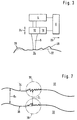
- the exemplary device shown in FIG Implementation of the present invention comprises Laser device 2 consisting of a laser head 3 and a laser beam generating device 4 with associated Control device 6, through which processing parameters, such as B. pulse frequency, pulse duration, degree of focus, Adjust feed, etc. of the working or laser beam 5 and let it be controlled.
- the Laser beam generating device 4 is via a light guide cable 7 connected to the laser head 3.
- the laser head 3 is attached to a laser head mount 8, which is part of a XYZ positioning device 10.
- the laser head 3 comprises also an imaging optics or focusing device 12, through which the laser beam 5 emerging from the laser head 3 on the surface of a workpiece 14 to be machined is focused. In this way, the laser head 3 and thus the laser beam 5 emerging from the laser head 3 move in all three spatial directions X, Y and Z and position.
- Measuring sensors 16 are also connected to the laser head 3, by means of which the contour of the surface of the machining workpiece 14, for example by triangulation, immediately before scanning the laser beam 5 and immediately after painting the Laser beam 5 can be determined. This way it becomes immediate the result of the editing during editing checked with the laser beam 5 and the number of The laser beam 5 can sweep over the 3D shaped surface optimized according to the desired work result will.
- the entire system is controlled by the control device 6, through which both the laser device 2, consisting of laser head 3 and laser beam generating device 4, as well as the positioning device 10 and Measuring sensors 16 are controlled and regulated.
- the control device 6 forms a together with the measuring sensors 16 2D or 3D contour measuring device 18.
- At the control device 6 is, for example, a microcomputer with a mass storage device. In these Storage device can, for example, CNC data of the machining workpiece 14 are stored. With the Contour measuring device 18 can thus the target-actual deviation be recorded and the number of processing steps and the same applies to the laser beam characteristics can be set.
- FIG. 3 shows a schematic illustration of that in FIG. 1 shown device with the laser beam generating device 4, the control device 6 and the imaging optics 12 from which the laser beam 5 emerges and on the surface of the workpiece 14 to be machined occurs, which is shown as contour line 20 (actual shape).
- the contour measuring device 18 is here in the imaging optics 12 integrated and the working beam 5 is simultaneously as Measuring beam used for the contour measuring device 18.
- the control device 6 can not be closer by means Actuators shown the distance between Imaging optics 12 and the workpiece surface 20 vary, which is indicated by a double arrow 24.
- Actuators are also the feed with respect to the workpiece 14 causes and controls. This is by an arrow 26 shown.
- the No transition from the current form 20 to the target form 22 necessarily with a single sweep of the Laser beam 5 reached. In the one already painted Area 28 is still a discrepancy between TARGET and Can be seen.
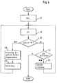
- Fig. 4 shows a flow chart for explaining essential Sub-steps of the inventive method with which Surface of a workpiece 14 from the actual shape in the SHOULD form is transferred.
- a step S1 is first the desired TARGET shape in a reference coordinate system fixed.
- the TARGET shape can be, for example, in the form of CNC or CAD data are available.
- a step S2 then the actual form of the still unprocessed or pre-machined workpiece 14 determined and in coordinates of the reference coordinate system.
- Step S3 is queried whether the actual value at the machining partial surface of the workpiece 14 already with the SHOULD value match or not. If it does asked in a step S4 whether all partial areas already exist edited or not. If so, it is Processing finished. Are not all partial areas processed, the transition to next partial area and the processing starts again at Step S2.
- Step S6 branches in which, based on the comparison of TARGET and ACTUAL data, based on external entries about the machining material, etc. the machining parameters for the Laser 2 and the strategy of machining is determined.
- step S7 the laser processing of the respective partial area corresponding to that in step S6 determined parameters executed. Then it will go back branches to step S2.
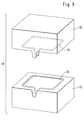
- Fig. 5 shows schematically a molding tool 30, which consists of two complementary parts 32 and 33.
- the two parts 32 and 33 can be put together and then by them enclosed cavity is then complemented by two Partial sealing surfaces 34 and 36 sealed.
- the Partial sealing surfaces 34 and 36 can have almost any shape be.
- Fig. 6 shows a flow chart for explaining the manufacture the sealing surfaces 34 and 36 with the method according to of the present invention.
- a step S1 first the target shape of only one of the two partial sealing surfaces, for example the partial sealing surface 34, fixed. Then the processing takes place according to the Steps S2 to S7 according to Fig. 4. Is the first partial sealing surface 34 completely processed, so in one Step S8 is the current form of processing after processing first partial sealing surface 34 as a target shape for the second Partial sealing surface 36 fixed. Processing the second Partial sealing surface 36 is then again analogous to that Steps S2 to S7 according to FIG. 4.
- FIG. 7 schematically shows a section through a part of the parts 32 and 33 of the molding tool 30 or a section through a part of the part sealing surfaces 34 and 36, areas 38 and 39 being shown enlarged.
- the two parts 32 and 33 more precisely their partial sealing surfaces 34 and 36, are arranged at a distance D from one another. Due to the roughness of the pre-machined partial sealing surfaces 34 and 36, the actual distance D i (actual distance) varies between opposing surface elements of the partial sealing surfaces 34 and 36.
- the two mold parts 32 and 33 are spatially fixed at a fixed distance from one another and the actual distance D i between opposing surface elements of the partial sealing surfaces 34 and 36 is measured.
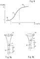
- FIG. 8 shows the material removal A caused by the laser beam 5 in ⁇ m as a function of the laser fluence (power density times irradiation time) in J / cm 2 .
- the result is a curve in the form of an elongated S with a flat curve in the area of low laser fluence, reference numeral 40, and in the area of high laser fluence, reference numeral 42, and a steep curve in the area of medium laser fluence, reference numeral 41.
- Those indicated in FIG. 8 Values apply to a copper vapor laser system as is known from DE-OS 44 12 443 and to which reference is made in full here.
- the region 40 or region 41 ends at approximately 1 J / cm 2 and the end of region 41 or the beginning of region 42 is approximately 250 J / cm 2 .
- the aluminum removal is in the range of 1 ⁇ m, region 40, and in region 42 with a laser fluence above 250 J / cm 2 , the aluminum removal is approximately 80 ⁇ m.
- the laser 2 is, according to the invention, in the areas 40 and 42 operated with a flat curve, since there is little Fluence fluctuations, such as those caused by variations the distance between the laser head 3 and to be machined Area due to vibration occur, hardly affect the size of the material removal. Hence is controlled and precise shaping easier. Of the Area 40 with low laser intensity is special advantageous when laser polishing, because a laser polishing large material removal is not desired.
- a focusing device or a Imaging optics 12 used which have a large Rayleigh length, preferably have SSge $$ 300 ⁇ m. It is known that real optical systems the focus B is not an ideal one mathematical point, but a spatial area.
- the Rayleigh length is a measure of the variation of the Cross section of the beam in the area of the geometric Focus. The smaller the Rayleigh length, the more the real beam matches the geometric one Beam path.
- 9a shows an optic 12 with a large Rayleigh length and 9b an optics 12 'with a small Rayleigh length. Varies in both cases the distance between imaging optics 12, 12 'and the area to be machined around the focal point B by ⁇ D, so fluctuates with a small Rayleigh length - Fig. 9b - Cross-sectional area F of the beam in the area between + ⁇ D and - ⁇ D and thus the laser intensity considerably more than with a large Rayleigh length - Fig. 9a.
- a Laser device 2 with an imaging optics 12 with a large Rayleigh length is therefore less sensitive to Vibration fluctuations.
Abstract
Description
Die vorliegende Erfindung betrifft ein Verfahren und eine Vorrichtung zum Bearbeiten, insbesondere zum Polieren und Strukturieren von beliebigen 3D-Formflächen bzw. Freiformflächen mittels eines Laser und die Anwendung dieses Verfahrens zur Herstellung von komplementären Dichtflächen an komplementären Formwerkzeugen.The present invention relates to a method and a Device for processing, in particular for polishing and Structuring of any 3D shape surfaces or free-form surfaces using a laser and applying this Process for the production of complementary sealing surfaces on complementary molds.
Aus der DE-OS 42 41 527 ist es bekannt, Laserstrahlen, insbesondere gepulste Excimer-Laser zum Glätten von Metalloberflächen zu verwenden. Durch die gepulste Beaufschlagung mit Energiedichten im Bereich von 5 × 10⁷ Watt/cm2 wird die Oberfläche des Metalls aufgeschmolzen. Durch die Verwendung eines UV- bzw. Excimer-Lasers geschieht dies nur in den obersten Randbereichen des Metalls bis zu einer Tiefe von 1 bis 2 µm, so daß keinerlei Verformungen oder Risse entstehen und die Metalloberfläche geglättet wird.From DE-OS 42 41 527 it is known to use laser beams, in particular pulsed excimer lasers for smoothing metal surfaces. The surface of the metal is melted by the pulsed exposure to energy densities in the range of 5 × 10 7 watts / cm 2 . By using a UV or excimer laser, this happens only in the uppermost edge areas of the metal to a depth of 1 to 2 µm, so that no deformations or cracks occur and the metal surface is smoothed.
Aus der DE-OS-42 17 530, der DE-OS-39 22 377, der EP-A-0 419 999 und der US-A-4,825,035 sind Verfahren und Vorrichtungen zum Härten von hochbeanspruchten metallischen Oberflächen, wie z. B. Kolbenlaufflächen, bekannt.From DE-OS-42 17 530, DE-OS-39 22 377, EP-A-0 419 999 and US-A-4,825,035 are methods and devices for hardening highly stressed metallic Surfaces such as B. piston treads known.
Aus der DE-OS 41 33 620 ist es bekannt, metallische Oberflächen mittels Laserstrahl zu strukturieren. Hierbei durchläuft der Laserstrahl Bahnkurven auf der Metalloberfläche, deren Form der gewünschten Strukturierung entspricht.From DE-OS 41 33 620 it is known metallic surfaces to structure using a laser beam. Here the laser beam travels along the metal surface, whose shape corresponds to the desired structuring.
Aus der DE-OS 44 01 597 ist eine Laserbearbeitungs- bzw. Laserschneidvorrichtung bekannt, bei der die zu erzeugende Schnittform in Form von CAD-Daten eingegeben werden kann. From DE-OS 44 01 597 a laser processing or Laser cutting device known in which the to be generated Cutting shape in the form of CAD data can be entered.
Aus der DE-OS 41 06 008 ist ein automatischer Schweißroboter bekannt, bei dem die Qualität der Schweißnähte online über optische Überwachung der Schweißnähte bzw. der Schweißspritzer überwacht wird.DE-OS 41 06 008 is an automatic welding robot known, where the quality of the welds online via optical monitoring of the weld seams or the Welding spatter is monitored.
Aus der DE-OS-37 11 470 ist ein Verfahren zum Herstellen eins dreidimensionalen Modells bekannt, das aus einer Vielzahl von Scheiben zusammengesetzt ist, die die Modellkonturen aufweisen und aus Plattenwerkstoff durch materialabtragende Bearbeitung mittels Laser hergestellt werden. Hierbei wird an einer bestimmten Stelle solange Material abgetragen, bis der SOLL-Wert erreicht ist.DE-OS-37 11 470 describes a method for manufacturing a three-dimensional model known from a Variety of disks is composed which the Have model contours and made of plate material material-removing processing made by laser will. This will last at a certain point Material removed until the TARGET value is reached.
Aus der DE-OS-42 19 809 ist ein Verfahren und eine Vorrichtung zum kontrollierten Abtragen von Schichten von einer Oberfläche mittels Laser bekannt. Um die Steuerung bzw. Regelung der Abtragung zu vereinfachen wird gewährleistet, daß aufeinanderfolgend bearbeitete Teilflächen immer eine konstante Fläche aufweisen.DE-OS-42 19 809 describes a method and a device for the controlled removal of layers of known a surface by means of laser. To control to simplify or regulate the deduction, that successively machined partial areas always have a constant area.
Die aus dem Stand der Technik bekannten Strahl- bzw. Laserbearbeitungsverfahren und -vorrichtungen weisen den Nachteil auf, daß im wesentlichen nur im voraus bekannte Formen damit bearbeitet werden können. Ein großtechnischer Einsatz und das Bearbeiten von beliebigen, kompliziert geformten 3D-Formflächen ist damit jedoch nicht möglich.The jet or Laser processing methods and devices have the Disadvantage that only known in advance essentially Shapes can be edited with it. An industrial one Use and editing of any, complicated 3D shaped surfaces are not possible.
Aus der US-A-4,986,664 ist ein Verfahren und eine Vorrichtung zum kontrollierten Materialabtrag. Hierbei wird die zu bearbeitende Oberfläche unmittelbar vor der Bearbeitung vermessen und auf der Basis dieser Meßdaten werden geeignete Bearbeitungsparameter gewählt.From US-A-4,986,664 is a method and a Device for controlled material removal. Here will the surface to be processed immediately before Measure machining and based on this measurement data suitable machining parameters are selected.
Aus der JP-A-63101092 ist eine Vorrichtung zum Bearbeiten von 3D-Formflächen bekannt, bei der die zu bearbeitenden Fläche unmittelbar vor der Bearbeitung vermessen wird. Anhand der Meßdaten und der gewünschten Form werden geeignete Bearbeitungsparameter errechnet und in eine entsprechende Materialbearbeitung umgesetzt.From JP-A-63101092 is a processing device known from 3D shaped surfaces in which the to be machined Area is measured immediately before processing. Based on the measurement data and the desired shape suitable processing parameters are calculated and converted into a appropriate material processing implemented.
Es ist Aufgabe der Erfindung ein Verfahren zum Herstellen von komplementären Dichtflächen and komplementären Formwerkzeugen bereitzustellen.It is the object of the invention to produce a method of complementary sealing surfaces and complementary To provide molds.
Die Lösung dieser Aufgabe erfolgt durch die Merkmale des
Anspruchs 1 bzw. 2.This problem is solved by the features of
Mit dem erfindungsgemäßen Verfahren lassen sich auf einfache Weise beliebig geformte, komplementäre Dichtflächen an komplementären Formwerkzeugen herstellen. Durch die hohe Genauigkeit des erfindungsgemäßen Verfahrens wird erreicht, daß die aufeinander zu liegen kommenden komplementären Dichtflächen sehr gut zueinander passen und damit sehr gut abdichten.With the method according to the invention, simple, arbitrarily shaped, complementary Create sealing surfaces on complementary molds. Due to the high accuracy of the method according to the invention is achieved that the coming to lie on each other complementary sealing surfaces fit together very well and seal very well with it.
Bei einer ersten Variante wird zunächst von den komplementären Teildichtflächenpaaren nur eine Hälfte bearbeitet und die nach der Bearbeitung ermittelte aktualisierte IST-Form wird als SOLL-Form für die zweite Hälfte der Teildichtflächenpaare verwendet. Dadurch werden Fehler bzw. Abweichungen der ersten Hälfte der Teildichtflächenpaare von der SOLL-Form bei der Bearbeitung der zweiten Hälfte der Teildichtflächenpaare ausgeglichen bzw. neutralisiert.In a first variant, the complementary Partial sealing surface pairs processed only one half and the updated actual form determined after processing is used as the TARGET form for the second half of the Partial sealing surface pairs used. This eliminates errors or Deviations in the first half of the partial sealing surface pairs of the TARGET shape when machining the second half the partial sealing surface pairs balanced or neutralized.
Bei einer zweiten Variante erfolgt die Bearbeitung der komplementären Teildichtflächen auf einen konstanten Abstand zwischen den komplementären Teildichtflächen hin. Damit lassen sich mit nur einem Satz von SOLL-Daten zwei benachbarte, komplementäre Dichtflächen bearbeiten bzw. herstellen.In a second variant, the complementary partial sealing surfaces at a constant distance between the complementary partial sealing surfaces. This means that two can be created with just one set of target data Machining adjacent, complementary sealing surfaces or produce.
Trägt man den durch einen Laserstrahl verursachten Materialabtrag als Funktion der Laserfluenz auf der zu bearbeitenden Fläche auf, so ergibt sich bei Konstanthaltung anderer Bearbeitungsparameter eine Kurve, die im Bereich niedriger Laserfluenz flach ansteigt, im Bereich mittlerer Laserfluenz stark ansteigt und im Bereich hoher Laserfluenz wieder flacher ansteigt. Gemäß einer bevorzugten Ausführungsform der Erfindung wird der Laser in den Bereichen mit flachem Anstieg betrieben, da sich dort geringfügige Fluenzschwankungen kaum auf den Materialabtrag auswirken, so daß sich glatte, gleichmäßige Oberflächen ergeben.One carries the material removal caused by a laser beam as a function of the laser fluence on the one to be processed Surface on, this results in keeping constant other machining parameters a curve that is in the range low laser fluence rises flat, in the medium range Laser fluence rises sharply and in the area of high laser fluence rises more gently again. According to a preferred Embodiment of the invention is the laser in the Areas with a flat rise are operated as there are minor Fluence fluctuations hardly affect the material removal impact so that there are smooth, even surfaces surrender.
Beim Laserpolieren von Werkstücken wird vorzugsweise der flache Bereich der Kurve bei niedriger Laserfluenz genutzt, da beim Laserpolieren kein Abtrag erwünscht ist.When laser polishing workpieces, the flat area of the curve used at low laser fluence, because no removal is desired when laser polishing.
Die übrigen Unteransprüche beziehen sich auf weitere vorteilhafte Ausgestaltungen der Erfindung.The remaining sub-claims relate to further advantageous Embodiments of the invention.
Die vorliegende Anmeldung ist eine Teilanmeldung zu EP 96909025.7 (Stammanmeldung). Die in der Stammanmeldung beschrieben Vorrichtung zum Laserpolieren eignet sich besonders für die Durchführung des erfindungsgemäßen Verfahrens.The present application is a divisional application to EP 96909025.7 (parent registration). The one in the parent application Device for laser polishing is suitable especially for the implementation of the invention Procedure.
Weitere Merkmale, Einzelheiten und Vorteile der Erfindung ergeben sich aus der nachfolgenden Beschreibung einer beispielhaften Ausführungsform anhand der Zeichnung. Es zeigt:
- Fig. 1
- eine schematische Darstellung einer beispielhaften Vorrichtung zur Ausführung des erfindungsgemäßen Verfahrens,
- Fig. 2
- ein Detail der Vorrichtung nach Fig. 1,
- Fig. 3
- eine schematische Darstellung zur Erläuterung der Arbeitsweise der Vorrichtung nach Fig. 1 und 2,
- Fig. 4
- ein Flußdiagramm zur Veranschaulichung wesentlicher Teilschritte des erfinderischen Verfahrens,
- Fig. 5
- eine schematische Darstellung eines Formwerkzeuges mit zwei komplementären Teilen,
- Fig. 6
- ein Flußdiagramm zur Erläuterung einer ersten Ausführungsform des Verfahrens zur Herstellung von Dichtflächen gemäß der vorliegenden Erfindung,
- Fig. 7
- eine schematische Darstellung zur Erläuterung einer zweiten Ausführungsform des Verfahrens zur Herstellung von Dichtflächen,
- Fig. 8
- eine qualitative Darstellung des Materialabtrags als Funktion der Laserfluenz, und
- Fig. 9a und 9b
- Abbildungsoptiken mit großer und kleiner Rayleighlänge.
- Fig. 1
- 2 shows a schematic representation of an exemplary device for carrying out the method according to the invention,
- Fig. 2
- 2 shows a detail of the device according to FIG. 1,
- Fig. 3
- 2 shows a schematic illustration to explain the mode of operation of the device according to FIGS. 1 and 2,
- Fig. 4
- 2 shows a flowchart to illustrate essential sub-steps of the inventive method,
- Fig. 5
- 1 shows a schematic illustration of a molding tool with two complementary parts,
- Fig. 6
- 2 shows a flowchart to explain a first embodiment of the method for producing sealing surfaces according to the present invention,
- Fig. 7
- 1 shows a schematic illustration to explain a second embodiment of the method for producing sealing surfaces,
- Fig. 8
- a qualitative representation of material removal as a function of laser fluence, and
- 9a and 9b
- Imaging optics with large and small Rayleigh lengths.
Die in Fig. 1 gezeigte beispielhafte Vorrichtung zur
Durchführung der vorliegenden Erfindung umfaßt eine
Lasereinrichtung 2 bestehend aus einem Laserkopf 3 und
einer Laserstrahlerzeugungseinrichtung 4 mit zugehöriger
Steuereinrichtung 6, durch die sich Bearbeitungsparameter,
wie z. B. Pulsfrequenz, Pulsdauer, Fokkussierungsgrad,
Vorschub, etc. des Arbeits- bzw. Laserstrahls 5 einstellen
und steuern bzw. regeln lassen. Die
Laserstrahlerzeugungseinrichtung 4 ist über ein Lichtleitkabel
7 mit dem Laserkopf 3 verbunden. Der Laserkopf 3 ist
an einer Laserkopfhalterung 8 befestigt, die Teil einer
XYZ-Positioniereinrichtung 10 ist. Der Laserkopf 3 umfaßt
auch eine Abbildungsoptik bzw. Fokussiereinrichtung 12,
durch die der aus dem Laserkopf 3 austretende Laserstrahl 5
auf der zu bearbeitenden Oberfläche eines Werkstücks 14
fokussiert wird. Auf diese Weise läßt sich der Laserkopf 3
und damit der aus dem Laserkopf 3 austretende Laserstrahl 5
in allen drei Raumrichtungen X, Y und Z bewegen und
positionieren.The exemplary device shown in FIG
Implementation of the present invention comprises
Mit dem Laserkopf 3 verbunden sind auch Meßsensoren 16,
mittels denen sich die die Kontur der Oberfläche des zu
bearbeitenden Werkstücks 14, beispielsweise durch Triangulation,
unmittelbar vor dem Überstreichen des Laserstrahls
5 und unmittelbar nach dem Überstreichen des
Laserstrahls 5 ermitteln läßt. Auf diese Weise wird unmittelbar
während der Bearbeitung das Ergebnis der Bearbeitung
mit dem Laserstrahl 5 überprüft und die Anzahl des
Überstreichens der 3D-Formfläche mit dem Laserstrahl 5 kann
entsprechend dem gewünschten Arbeitsergebnis optimiert
werden.Measuring
Die Steuerung der gesamten Anlage erfolgt durch die Steuereinrichtung
6, durch die sowohl die Lasereinrichtung 2,
bestehend aus Laserkopf 3 und Laserstrahlerzeugungseinrichtung
4, als auch die Positioniereinrichtung 10 und
Meßsensoren 16 gesteuert und geregelt werden. Die Steuereinrichtung
6 bildet zusammen mit den Meßsensoren 16 eine
2D- bzw. 3D-Konturmeßeinrichtung 18. Bei der Steuereinrichtung
6 handelt es sich beispielsweise um einen Mikrocomputer
mit einer Massenspeichereinrichtung. In diese
Speichereinrichtung können beispielsweise CNC-Daten des zu
bearbeitenden Werkstücks 14 eingespeichert werden. Mit der
Konturmeßeinrichtung 18 kann damit die Soll-Ist-Abweichung
erfaßt werden und die Anzahl der Bearbeitungsschritte und
ebenso die Laserstrahlcharakteristiken entsprechend
eingestellt werden.The entire system is controlled by the
Fig. 3 zeigt eine schematische Darstellung der in Fig. 1
dargestellten Vorrichtung mit der Laserstrahlerzeugungseinrichtung
4, der Steuereinrichtung 6 und der Abbildungsoptik
12 aus der der Laserstrahl 5 austritt und auf
die zu bearbeitende Oberfläche des Werkstücks 14 auftritt,
das als Konturlinie 20 (IST-Form) dargestellt ist. FIG. 3 shows a schematic illustration of that in FIG. 1
shown device with the laser
Strichliert ist die SOLL-Form 22 dargestellt. Die Konturmeßeinrichtung
18 ist hier in die Abbildungsoptik 12
integriert und der Arbeitsstrahl 5 wird gleichzeitig als
Meßstrahl für die Konturmeßeinrichtung 18 verwendet. Durch
die Steuereinrichtung 6 läßt sich mittels nicht näher
dargestellter Stellantriebe der Abstand zwischen
Abbildungsoptik 12 und der Werkstückoberfläche 20 variieren,
was durch einen Doppelpfeil 24 angedeutet ist. Ebenfalls
mit der Steuereinrichtung 6 und entsprechender
Stellantriebe wird auch der Vorschub bezüglich des Werkstücks
14 bewirkt und gesteuert. Dies ist durch einen Pfeil
26 dargestellt. Wie aus Fig. 3 zu ersehen ist, wird der
Übergang von der IST-Form 20 zur SOLL-Form 22 nicht
notwendigerweise mit einem einmaligen Überstreichen des
Laserstrahls 5 erreicht. In dem bereits überstrichenen
Bereich 28 ist immer noch eine Abweichung zwischen SOLL-und
IST zu sehen.SHOULD shape 22 is shown in dashed lines. The
Um die Materialbearbeitung unempfindlicher gegenüber Vibrationen und zittern zu machen wird der Bearbeitungsstrahl mit einer Rayleighlänge von 300 µm und größer erzeugt. Details hierzu sind in Verbindung mit Fig. 9 erläutert.To make the material processing less sensitive to It will make vibrations and tremors Processing beam with a Rayleigh length of 300 µm and generated larger. Details can be found in connection with Fig. 9 explained.
Fig. 4 zeigt eine Flußdiagramm zur Erläuterung wesentlicher
Teilschritte des erfindungsgemäßen Verfahrens mit dem die
Oberfläche eines Werkstücks 14 von der IST-Form in die
SOLL-Form überführt wird. In einem Schritt S1 wird zunächst
in einem Referenzkoordinatensystem die gewünschte SOLL-Form
festgelegt. Die SOLL-Form kann beispielsweise in Form von
CNC- oder CAD-Daten vorliegen. In einem Schritt S2 wird
dann die IST-Form des noch unbearbeiteten oder
vorbearbeiteten Werkstücks 14 ermittelt und in Koordinaten
des Referenzkoordinatensystems dargestellt. In einem
Schritt S3 wird abgefragt, ob der IST-Wert an der zu
bearbeitenden Teilfläche des Werkstücks 14 bereits mit dem
SOLL-Wert übereinstimmt oder nicht. Ist dies der Fall wird
in einem Schritt S4 abgefragt, ob bereits alle Teilflächen
bearbeitet sind oder nicht. Ist dies der Fall, ist die
Bearbeitung beendet. Sind noch nicht alle Teilflächen
bearbeitet, so erfolgt in einem Schritt S5 der Übergang zur
nächsten Teilfläche und die Bearbeitung beginnt wieder bei
Schritt S2.Fig. 4 shows a flow chart for explaining essential
Sub-steps of the inventive method with which
Surface of a workpiece 14 from the actual shape in the
SHOULD form is transferred. In a step S1 is first
the desired TARGET shape in a reference coordinate system
fixed. The TARGET shape can be, for example, in the form of
CNC or CAD data are available. In a step S2
then the actual form of the still unprocessed or
Ergibt die Abfrage in Schritt S3 ein NEIN, so wird zu einem
Schritt S6 verzweigt, in dem aufgrund des Vergleichs von
SOLL- und IST-Daten, aufgrund externer Eingaben über das zu
bearbeitende Material, etc. die Bearbeitungsparamer für den
Laser 2 und die Strategie der Bearbeitung ermittelt wird.
In einem Schritt S7 wird dann die Laserbearbeitung der
jeweiligen Teilfläche entsprechend den in Schritt S6
ermittelten Parametern ausgeführt. Anschließend wird zurück
zu dem Schritt S2 verzweigt.If the query in step S3 yields a NO, it becomes a
Step S6 branches in which, based on the comparison of
TARGET and ACTUAL data, based on external entries about the
machining material, etc. the machining parameters for the
Fig. 5 zeigt schematisch ein Formwerkzeug 30, das aus zwei
komplementären Teilen 32 und 33 besteht. Die beiden Teile
32 und 33 lassen sich zusammenfügen und der von ihnen dann
umschlossene Hohlraum wird dann durch zwei komplementäre
Teildichtflächen 34 und 36 abgedichtet. Die
Teildichtflächen 34 und 36 können nahezu beliebig geformt
sein.Fig. 5 shows schematically a
Fig. 6 zeigt ein Flußdiagramm zur Erläuterung der Herstellung
der Dichtflächen 34 und 36 mit dem Verfahren gemäß
der vorliegenden Erfindung. In einem Schritt S1' wird
zunächst die SOLL-Form von nur einer der beiden Teildichtflächen,
beispielsweise der Teildichtfläche 34,
festgelegt. Anschließend erfolgt die Bearbeitung gemäß den
Schritten S2 bis S7 nach Fig. 4. Ist die erste Teildichtfläche
34 vollständig bearbeitet, so wird in einem
Schritt S8 die nach Bearbeitung vorliegende IST-Form der
ersten Teildichtfläche 34 als SOLL-Form für die zweite
Teildichtfläche 36 festegelegt. Die Bearbeitung der zweiten
Teildichtfläche 36 erfolgt dann wiederum analog den
Schritten S2 bis S7 gemäß Fig. 4.Fig. 6 shows a flow chart for explaining the manufacture
the sealing surfaces 34 and 36 with the method according to
of the present invention. In a step S1 '
first the target shape of only one of the two partial sealing surfaces,
for example the
Fig. 7 zeigt schematisch einen Schnitt durch einen Teil der
Teile 32 und 33 des Formwerkzeugs 30 bzw. einen Schnitt
durch einen Teil der Teildichtflächen 34 und 36, wobei
Bereiche 38 und 39 vergrößert dargestellt sind. Die beiden
Teile 32 und 33, genauer deren Teildichtflächen 34 und 36
sind mit einem Abstand D voneinander entfernt angeordnet.
Aufgrund der Rauhigkeit der vorbearbeiteten
Teildichtflächen 34 und 36 variiert der tatsächliche Abstand
Di (IST-Abstand) zwischen einander gegenüberliegenden
Flächenelementen der Teildichtflächen 34 und 36. Die beiden
Formwerkzeugteile 32 und 33 werden in festem Abstand
zueinander räumlich fixiert und der IST-Abstand Di zwischen
einander gegebüberliegenden Flächenelementen der
Teildichtflächen 34 und 36 wird gemessen. Anschließend wird
der SOLL-Abstand Ds festgelegt und die beiden Teildichtflächen
34 und 36 werden mit dem Laser derart bearbeitet,
daß innerhalb der Toleranzen
In Fig. 8 ist der durch den Laserstrahl 5 verursachte
Materialabtrag A in µm als Funktion der Laserfluenz
(Leistungsdichte mal Bestrahlungszeit) in J/cm2 aufgetragen.
Es ergibt sich ein Kurvenverlauf in der Form eines
langgezogenen S mit einem flachen Kurvenverlauf im Bereich
geringer Laserfluenz, Bezugszeichen 40, und im Bereich
hoher Laserfluenz, Bezugszeichen 42, und einem steilen
Kurvenverlauf im Bereich mittlerer Laserfluenz,
Bezugszeichen 41. Die in Fig. 8 angegebenen Werte gelten
für einen Kupferdampflasersystem, wie er aus der DE-OS
44 12 443 bekannt ist und auf die hier vollinhaltlich
bezug genommen wird. Für einen solchen Kupferdampflaser und
Aluminium als zu bearbeitendem Material endet der Bereich
40 bzw. beginnt der Bereich 41 bei ca. 1 J/cm2 und das Ende
des Bereichs 41 bzw. der Beginn des Bereichs 42 liegt bei
ca. 250 J/cm2. Bis zu einer Laserfluenz von ungefähr
1 J/cm2 liegt der Aluminiumabtrag im Bereich von 1 µm,
Bereich 40, und im Bereich 42 mit einer Laserfluenz über
250 J/cm2 liegt der Aluminiumabtrag bei ca. 80 µm.8 shows the material removal A caused by the
Der Laser 2 wird erfindungsgemäß in den Bereichen 40 und 42
mit flachem Kurvenverlauf betrieben, da dort geringe
Fluenzschwankungen, wie sie beispielsweise durch Variationen
des Abstands zwischen Laserkopf 3 und zu bearbeitender
Fläche aufgrund von Vibrationen auftreten, sich kaum
auf die Größe des Materialabtrags auswirken. Folglich ist
eine kontrollierte und genaue Formgebung einfacher. Der
Bereich 40 mit niedriger Laserintensität ist insbesondere
beim Laserpolieren vorteilhaft, da beim Laserpolieren ein
großer Materialabtrag nicht gewünscht ist.The
Eine weitere Maßnahme, um die Lasereinrichtung 2 unempfindlicher
gegenüber Lage- bzw. Positionsschwankungen zu
machen, wie sie bei Roboterarmen unweigerlich auftreten,
wird anhand von Fig. 9a und 9b erläutert. Hierzu wird in
der Lasereinrichtung 2 eine Fokussiervorrichtung bzw. eine
Abbildungsoptik 12 verwendet, die eine große Rayleighlänge,
vorzugsweise SSge$$ 300 µm aufweisen. Bekanntlich ist bei realen
optischen Systemen der Brennpunkt B kein idealer
mathematischer Punkt, sondern ein Raumbereich. Die
Rayleighlänge ist ein Maß für die Variation des
Querschnitts des Strahlenbündels im Bereich des geometrischen
Brennpunkts. Je kleiner die Rayleighlänge ist,
desto mehr stimmt das reale Strahlenbündel mit dem geometrischen
Strahlengang überein.Another measure to make the
Fig. 9a zeigt eine Optik 12 mit großer Rayleighlänge und
Fig. 9b eine Optik 12' mit kleiner Rayleighlänge. Variiert
in beiden Fällen der Abstand zwischen Abbildungsoptik 12,
12' und zu bearbeitender Fläche um den Brennpunkt B um ΔD,
so schwankt bei kleiner Rayleighlänge - Fig. 9b - die
Querschnittsfläche F des Strahlenbündels im Bereich
zwischen +ΔD und -ΔD und damit die Laserintensität
erheblich mehr als bei großer Rayleighlänge - Fig. 9a. Eine
Lasereinrichtung 2 mit einer Abbildungsoptik 12 mit großer
Rayleighlänge ist daher unempfindlicher gegenüber
Vibrationsschwankungen.9a shows an optic 12 with a large Rayleigh length and
9b an optics 12 'with a small Rayleigh length. Varies
in both cases the distance between
Claims (11)
Applications Claiming Priority (3)
| Application Number | Priority Date | Filing Date | Title |
|---|---|---|---|
| DE29505985U DE29505985U1 (en) | 1995-04-06 | 1995-04-06 | Device for processing, in particular for polishing and structuring any 3D shape surfaces by means of a laser beam |
| DE29505985U | 1995-04-06 | ||
| EP96909025A EP0819036B1 (en) | 1995-04-06 | 1996-04-09 | Process and device for laser machining of any 3d surface |
Related Parent Applications (2)
| Application Number | Title | Priority Date | Filing Date |
|---|---|---|---|
| EP96909025A Division EP0819036B1 (en) | 1995-04-06 | 1996-04-09 | Process and device for laser machining of any 3d surface |
| EP96909025.7 Division | 1996-10-10 |
Publications (2)
| Publication Number | Publication Date |
|---|---|
| EP0854004A1 true EP0854004A1 (en) | 1998-07-22 |
| EP0854004B1 EP0854004B1 (en) | 2001-10-04 |
Family
ID=8006554
Family Applications (2)
| Application Number | Title | Priority Date | Filing Date |
|---|---|---|---|
| EP96909025A Expired - Lifetime EP0819036B1 (en) | 1995-04-06 | 1996-04-09 | Process and device for laser machining of any 3d surface |
| EP98103286A Expired - Lifetime EP0854004B1 (en) | 1995-04-06 | 1996-04-09 | Process for manufacturing sealing faces on complementary form tools |
Family Applications Before (1)
| Application Number | Title | Priority Date | Filing Date |
|---|---|---|---|
| EP96909025A Expired - Lifetime EP0819036B1 (en) | 1995-04-06 | 1996-04-09 | Process and device for laser machining of any 3d surface |
Country Status (13)
| Country | Link |
|---|---|
| US (1) | US6043452A (en) |
| EP (2) | EP0819036B1 (en) |
| JP (1) | JP3258331B2 (en) |
| KR (1) | KR100311839B1 (en) |
| AT (2) | ATE179107T1 (en) |
| AU (1) | AU5269496A (en) |
| BR (1) | BR9604851A (en) |
| CA (1) | CA2217372C (en) |
| DE (3) | DE29505985U1 (en) |
| DK (2) | DK0819036T3 (en) |
| ES (2) | ES2162356T3 (en) |
| PT (1) | PT854004E (en) |
| WO (1) | WO1996031315A1 (en) |
Cited By (3)
| Publication number | Priority date | Publication date | Assignee | Title |
|---|---|---|---|---|
| DE102012111797A1 (en) * | 2012-12-05 | 2014-06-18 | Reinhard Caliebe | Device, useful for processing workpiece, comprises holder in which workpiece is clamped, laser device emitting first laser beam on to jet of water, drive unit, and control unit, where laser device is positioned at different positions |
| DE102012111796A1 (en) * | 2012-12-05 | 2014-06-18 | Reinhard Caliebe | Processing device useful for workpiece, comprises workpiece holder for clamping workpiece, first laser device for emitting first laser beam guided in water jet, and for eroding material from workpiece, drive device, and control device |
| DE102018209929A1 (en) * | 2018-06-20 | 2019-12-24 | Bayerische Motoren Werke Aktiengesellschaft | Method for processing a component of a motor vehicle |
Families Citing this family (77)
| Publication number | Priority date | Publication date | Assignee | Title |
|---|---|---|---|---|
| GB2328636A (en) * | 1997-08-29 | 1999-03-03 | Rye Machinery Ltd | A support for a laser tool |
| PT1119448E (en) * | 1998-10-05 | 2003-10-31 | Mystix Ltd | SIMILAR ARTICLE FOR LITHOGRAPH AND MANUFACTURING METHOD |
| KR100628438B1 (en) * | 1998-12-04 | 2006-12-05 | 삼성전자주식회사 | Manufacturing method of liquid crystal display panel |
| DE29904489U1 (en) * | 1999-03-11 | 1999-05-27 | Precitec Gmbh | Working head for processing a workpiece using a laser beam |
| US6300595B1 (en) * | 1999-06-03 | 2001-10-09 | High Tech Polishing, Inc. | Method of three dimensional laser engraving |
| US6552301B2 (en) | 2000-01-25 | 2003-04-22 | Peter R. Herman | Burst-ultrafast laser machining method |
| KR100364195B1 (en) * | 2000-06-12 | 2002-12-11 | 한국기계연구원 | Method for making a minute parts using excimer laser beam |
| US6492615B1 (en) * | 2000-10-12 | 2002-12-10 | Scimed Life Systems, Inc. | Laser polishing of medical devices |
| US7767928B2 (en) | 2001-09-05 | 2010-08-03 | Lasertec Gmbh | Depth measurement and depth control or automatic depth control for a hollow to be produced by a laser processing device |
| DE10228743B4 (en) * | 2002-06-27 | 2005-05-04 | Fraunhofer-Gesellschaft zur Förderung der angewandten Forschung e.V. | Method for smoothing and polishing surfaces by machining with laser radiation |
| DE10317579B4 (en) * | 2003-04-16 | 2016-04-14 | Lasertec Gmbh | Method and device for producing a die in a workpiece |
| DE10324439B4 (en) * | 2003-05-28 | 2008-01-31 | Lasertec Gmbh | Method and device for producing a die |
| DE10342750B4 (en) * | 2003-09-16 | 2008-06-19 | Fraunhofer-Gesellschaft zur Förderung der angewandten Forschung e.V. | Method for smoothing and polishing or structuring surfaces with laser radiation |
| DE10345081A1 (en) * | 2003-09-26 | 2005-05-19 | Peguform Gmbh & Co. Kg | Method for processing a three-dimensional surface |
| JP5013699B2 (en) * | 2005-10-21 | 2012-08-29 | 株式会社キーエンス | Three-dimensional machining data setting device, three-dimensional machining data setting method, three-dimensional machining data setting program, computer-readable recording medium, recorded device, and laser machining device |
| US7449699B1 (en) | 2006-04-20 | 2008-11-11 | Sandia Corporation | Method and apparatus for creating a topography at a surface |
| US20070279969A1 (en) * | 2006-06-02 | 2007-12-06 | Raytheon Company | Intrusion detection apparatus and method |
| JP5132900B2 (en) * | 2006-06-28 | 2013-01-30 | 株式会社キーエンス | Laser processing condition setting device, laser processing device, laser processing condition setting method, laser processing condition setting program |
| JP4958489B2 (en) * | 2006-06-30 | 2012-06-20 | 株式会社キーエンス | Laser processing device, laser processing condition setting device, laser processing condition setting method, laser processing condition setting program |
| JP4795886B2 (en) | 2006-07-27 | 2011-10-19 | 株式会社キーエンス | Laser processing device, laser processing condition setting device, laser processing condition setting method, laser processing condition setting program |
| JP4956107B2 (en) * | 2006-09-15 | 2012-06-20 | 株式会社キーエンス | Laser processing data generation apparatus, laser processing data generation method, computer program, and laser marking system |
| KR100784939B1 (en) | 2006-12-22 | 2007-12-13 | 주식회사 아스트 | the synchronous control method for equipment of airplane body using shape data of three dimensions |
| US8674259B2 (en) * | 2008-05-28 | 2014-03-18 | Caterpillar Inc. | Manufacturing system for producing reverse-tapered orifice |
| US20110087457A1 (en) * | 2009-10-09 | 2011-04-14 | Furmanite Worldwide, Inc. | Surface measurement, selection, and machining |
| US20110087363A1 (en) * | 2009-10-09 | 2011-04-14 | Furmanite Worldwide, Inc. | Surface measurement, selection, and machining |
| US20110085175A1 (en) * | 2009-10-09 | 2011-04-14 | Furmanite Worldwide, Inc. | Surface measurement, selection, and machining |
| US9056584B2 (en) | 2010-07-08 | 2015-06-16 | Gentex Corporation | Rearview assembly for a vehicle |
| DE102010033053B4 (en) * | 2010-08-02 | 2013-03-07 | Fraunhofer-Gesellschaft zur Förderung der angewandten Forschung e.V. | Process for the shaping remelting of workpieces |
| DE102011103793A1 (en) * | 2011-03-10 | 2012-09-27 | Fraunhofer-Gesellschaft zur Förderung der angewandten Forschung e.V. | Process for manufacturing optical elements by machining with energetic radiation |
| JP5459255B2 (en) * | 2011-04-08 | 2014-04-02 | 株式会社安川電機 | Robot system |
| EP2511656A1 (en) * | 2011-04-14 | 2012-10-17 | Hexagon Technology Center GmbH | Measuring system for determining the 3D coordinates of an object surface |
| FR2974746B1 (en) * | 2011-05-02 | 2014-07-18 | Snecma | METHOD FOR CLEANING AND REMOVING A TURBOMOTOR BLADE BY MEANS OF AN IMPULSE LASER |
| DE102011078825B4 (en) * | 2011-07-07 | 2018-07-19 | Sauer Gmbh Lasertec | Method and laser processing machine for processing a workpiece |
| DE112012003797B4 (en) | 2011-12-14 | 2016-12-15 | Panasonic Intellectual Property Management Co., Ltd. | Processing means determining method for a combined ultraprecision processing apparatus and combined ultra-precision processing apparatus |
| WO2013089279A1 (en) | 2011-12-14 | 2013-06-20 | パナソニック株式会社 | Machining data generation method for ultraprecise combined machining device, and ultraprecise combined machining device |
| US9874437B2 (en) * | 2011-12-28 | 2018-01-23 | Femtonics Kft. | Method for the 3-dimensional measurement of a sample with a measuring system comprising a laser scanning microscope and such measuring system |
| US9316347B2 (en) | 2012-01-24 | 2016-04-19 | Gentex Corporation | Rearview assembly with interchangeable rearward viewing device |
| US8879139B2 (en) | 2012-04-24 | 2014-11-04 | Gentex Corporation | Display mirror assembly |
| DE102012107827A1 (en) * | 2012-08-24 | 2014-02-27 | Sandvik Surface Solutions Division Of Sandvik Materials Technology Deutschland Gmbh | Method for producing gloss effects on pressing tools |
| WO2014032042A1 (en) | 2012-08-24 | 2014-02-27 | Gentex Corporation | Shaped rearview mirror assembly |
| US9327648B2 (en) | 2013-01-04 | 2016-05-03 | Gentex Corporation | Rearview assembly with exposed carrier plate |
| WO2014110124A1 (en) | 2013-01-09 | 2014-07-17 | Gentex Corporation | Printed appliqué and method thereof |
| FI20135385L (en) | 2013-04-18 | 2014-10-19 | Cajo Tech Oy | Color marking of metal surfaces |
| KR101470175B1 (en) * | 2013-06-26 | 2014-12-08 | 현대자동차주식회사 | Method for laser cutting for appearance of mold |
| CN105555612B (en) | 2013-09-24 | 2018-06-01 | 金泰克斯公司 | Show mirror assembly |
| WO2016044746A1 (en) | 2014-09-19 | 2016-03-24 | Gentex Corporation | Rearview assembly |
| WO2016073848A1 (en) | 2014-11-07 | 2016-05-12 | Gentex Corporation | Full display mirror actuator |
| WO2016077583A1 (en) | 2014-11-13 | 2016-05-19 | Gentex Corporation | Rearview mirror system with a display |
| WO2016090126A2 (en) | 2014-12-03 | 2016-06-09 | Gentex Corporation | Display mirror assembly |
| USD746744S1 (en) | 2014-12-05 | 2016-01-05 | Gentex Corporation | Rearview device |
| CN104759753B (en) * | 2015-03-30 | 2016-08-31 | 江苏大学 | The co-ordination of multisystem automatization improves the method for induced with laser cavitation reinforcement |
| US9995854B2 (en) | 2015-04-20 | 2018-06-12 | Gentex Corporation | Rearview assembly with applique |
| EP3297870B1 (en) | 2015-05-18 | 2020-02-05 | Gentex Corporation | Full display rearview device |
| US10029330B2 (en) * | 2015-06-17 | 2018-07-24 | The Boeing Company | Hybrid laser machining of multi-material stack-ups |
| US9994156B2 (en) | 2015-10-30 | 2018-06-12 | Gentex Corporation | Rearview device |
| EP3368374B1 (en) | 2015-10-30 | 2023-12-27 | Gentex Corporation | Toggle paddle |
| USD845851S1 (en) | 2016-03-31 | 2019-04-16 | Gentex Corporation | Rearview device |
| USD817238S1 (en) | 2016-04-29 | 2018-05-08 | Gentex Corporation | Rearview device |
| US10025138B2 (en) | 2016-06-06 | 2018-07-17 | Gentex Corporation | Illuminating display with light gathering structure |
| JP6348149B2 (en) * | 2016-07-08 | 2018-06-27 | ファナック株式会社 | Laser processing robot system that performs laser processing using a robot |
| USD809984S1 (en) | 2016-12-07 | 2018-02-13 | Gentex Corporation | Rearview assembly |
| DE102017002986B4 (en) | 2016-12-13 | 2019-08-29 | AIXLens GmbH | Method for producing a transmission optical system and intraocular lens |
| DE102017007219A1 (en) | 2016-12-13 | 2018-06-14 | Fraunhofer-Gesellschaft zur Förderung der angewandten Forschung e.V. | Method for producing a transmitive or reflective optic and lens |
| USD854473S1 (en) | 2016-12-16 | 2019-07-23 | Gentex Corporation | Rearview assembly |
| CN108393579A (en) * | 2017-02-07 | 2018-08-14 | 京东方科技集团股份有限公司 | Laser processing device and laser processing |
| JP6464213B2 (en) * | 2017-02-09 | 2019-02-06 | ファナック株式会社 | Laser processing system having laser processing head and imaging device |
| EP3406389A1 (en) * | 2017-05-23 | 2018-11-28 | Siemens Aktiengesellschaft | Method for detecting and processing defined contours in the cutting of a solid body by means of a high energy beam |
| DE102017113804B4 (en) * | 2017-06-22 | 2020-08-06 | Rolf Rascher | Method and device for monitoring a laser polishing process |
| US10744539B2 (en) * | 2017-10-27 | 2020-08-18 | The Boeing Company | Optimized-coverage selective laser ablation systems and methods |
| WO2019116452A1 (en) * | 2017-12-12 | 2019-06-20 | 株式会社ニコン | Treatment device and treatment method, processing method, and shaping device and shaping method |
| DE102018102108B4 (en) * | 2018-01-31 | 2019-10-10 | Acsys Lasertechnik Gmbh | Method for laser-based generation of a structure on a rake face of a cutting tool |
| DE102018106362A1 (en) * | 2018-03-19 | 2019-09-19 | Technische Universität Hamburg | DEVICES AND METHOD FOR PROCESSING METALLIC OBJECTS |
| DE102018108145A1 (en) * | 2018-04-06 | 2019-10-10 | Volkswagen Ag | Method for processing surfaces of components produced by means of 3D printing, and such a machined component |
| DE102018122605A1 (en) | 2018-09-14 | 2020-03-19 | Fraunhofer-Gesellschaft zur Förderung der angewandten Forschung e.V. | Method for smoothing a component surface area |
| JP6902175B1 (en) * | 2019-08-23 | 2021-07-14 | トーカロ株式会社 | Surface treatment method |
| CN112756777B (en) * | 2020-12-29 | 2022-12-02 | 华中科技大学 | Laser blackening treatment method for metal surface |
| CN114959691A (en) * | 2022-06-10 | 2022-08-30 | 北京工商大学 | Surface modification equipment for 3D printing of titanium alloy and surface modification method thereof |
Citations (1)
| Publication number | Priority date | Publication date | Assignee | Title |
|---|---|---|---|---|
| US4986664A (en) * | 1984-02-07 | 1991-01-22 | International Technical Associates | System and process for controlled removal of material to produce a desired surface contour |
Family Cites Families (14)
| Publication number | Priority date | Publication date | Assignee | Title |
|---|---|---|---|---|
| DE2624121A1 (en) * | 1976-05-28 | 1977-12-15 | Siemens Ag | METHOD FOR EXACTLY PROCESSING A WORKPIECE ARRANGED IN THE WORKING FIELD OF A PROCESSING LASER AND DEVICE FOR EXECUTING THE PROCESS |
| US4469930A (en) * | 1981-07-17 | 1984-09-04 | Fuji Tool & Die Co., Ltd. | Three-dimensional laser cutting system by a playback method |
| US4752668A (en) * | 1986-04-28 | 1988-06-21 | Rosenfield Michael G | System for laser removal of excess material from a semiconductor wafer |
| US4825035A (en) * | 1986-09-20 | 1989-04-25 | Mitsubishi Denki Kabushiki Kaisha | Control apparatus for energy beam hardening |
| JPS63101092A (en) * | 1986-10-18 | 1988-05-06 | Toshiba Corp | Laser beam machine |
| US4977512A (en) * | 1987-02-05 | 1990-12-11 | Shibuya Kogyo Co., Ltd. | Three dimensional simultaneous machining and measuring system |
| DE3711470A1 (en) * | 1987-04-04 | 1988-10-27 | Fraunhofer Ges Forschung | Method of producing a three-dimensional model |
| DD263447A1 (en) * | 1987-09-02 | 1989-01-04 | Zeiss Jena Veb Carl | ARRANGEMENT FOR THE OPERATIONAL TREATMENT OF THE EYEBERRY SKIN |
| US4915757A (en) * | 1988-05-05 | 1990-04-10 | Spectra-Physics, Inc. | Creation of three dimensional objects |
| US4914270A (en) * | 1988-11-08 | 1990-04-03 | University Of Southern California | Method and apparatus for shaping articles using a laser beam |
| US5057184A (en) * | 1990-04-06 | 1991-10-15 | International Business Machines Corporation | Laser etching of materials in liquids |
| US5475197A (en) * | 1992-06-17 | 1995-12-12 | Carl-Zeiss-Stiftung | Process and apparatus for the ablation of a surface |
| DE4333501C2 (en) * | 1993-10-01 | 1998-04-09 | Univ Stuttgart Strahlwerkzeuge | Method for determining the instantaneous penetration depth of a machining laser beam into a workpiece and device for carrying out this method |
| US5656186A (en) * | 1994-04-08 | 1997-08-12 | The Regents Of The University Of Michigan | Method for controlling configuration of laser induced breakdown and ablation |
-
1995
- 1995-04-06 DE DE29505985U patent/DE29505985U1/en not_active Expired - Lifetime
-
1996
- 1996-04-09 ES ES98103286T patent/ES2162356T3/en not_active Expired - Lifetime
- 1996-04-09 AU AU52694/96A patent/AU5269496A/en not_active Abandoned
- 1996-04-09 AT AT96909025T patent/ATE179107T1/en not_active IP Right Cessation
- 1996-04-09 DE DE59607842T patent/DE59607842D1/en not_active Expired - Lifetime
- 1996-04-09 DK DK96909025T patent/DK0819036T3/en active
- 1996-04-09 ES ES96909025T patent/ES2130808T3/en not_active Expired - Lifetime
- 1996-04-09 CA CA002217372A patent/CA2217372C/en not_active Expired - Fee Related
- 1996-04-09 PT PT98103286T patent/PT854004E/en unknown
- 1996-04-09 DE DE59601716T patent/DE59601716D1/en not_active Expired - Lifetime
- 1996-04-09 BR BR9604851-4A patent/BR9604851A/en not_active Application Discontinuation
- 1996-04-09 AT AT98103286T patent/ATE206340T1/en not_active IP Right Cessation
- 1996-04-09 WO PCT/DE1996/000621 patent/WO1996031315A1/en active IP Right Grant
- 1996-04-09 JP JP52986296A patent/JP3258331B2/en not_active Expired - Fee Related
- 1996-04-09 US US08/930,429 patent/US6043452A/en not_active Expired - Fee Related
- 1996-04-09 EP EP96909025A patent/EP0819036B1/en not_active Expired - Lifetime
- 1996-04-09 DK DK98103286T patent/DK0854004T3/en active
- 1996-04-09 EP EP98103286A patent/EP0854004B1/en not_active Expired - Lifetime
- 1996-04-09 KR KR1019970707004A patent/KR100311839B1/en not_active IP Right Cessation
Patent Citations (1)
| Publication number | Priority date | Publication date | Assignee | Title |
|---|---|---|---|---|
| US4986664A (en) * | 1984-02-07 | 1991-01-22 | International Technical Associates | System and process for controlled removal of material to produce a desired surface contour |
Cited By (5)
| Publication number | Priority date | Publication date | Assignee | Title |
|---|---|---|---|---|
| DE102012111797A1 (en) * | 2012-12-05 | 2014-06-18 | Reinhard Caliebe | Device, useful for processing workpiece, comprises holder in which workpiece is clamped, laser device emitting first laser beam on to jet of water, drive unit, and control unit, where laser device is positioned at different positions |
| DE102012111796A1 (en) * | 2012-12-05 | 2014-06-18 | Reinhard Caliebe | Processing device useful for workpiece, comprises workpiece holder for clamping workpiece, first laser device for emitting first laser beam guided in water jet, and for eroding material from workpiece, drive device, and control device |
| DE102012111796B4 (en) * | 2012-12-05 | 2017-04-20 | Reinhard Caliebe | Machining device for a workpiece |
| DE102012111797B4 (en) * | 2012-12-05 | 2017-04-20 | Reinhard Caliebe | Machining device for a workpiece |
| DE102018209929A1 (en) * | 2018-06-20 | 2019-12-24 | Bayerische Motoren Werke Aktiengesellschaft | Method for processing a component of a motor vehicle |
Also Published As
| Publication number | Publication date |
|---|---|
| DK0819036T3 (en) | 1999-10-25 |
| DE59601716D1 (en) | 1999-05-27 |
| WO1996031315A1 (en) | 1996-10-10 |
| EP0819036A1 (en) | 1998-01-21 |
| ES2162356T3 (en) | 2001-12-16 |
| CA2217372C (en) | 2001-10-02 |
| US6043452A (en) | 2000-03-28 |
| ES2130808T3 (en) | 1999-07-01 |
| DK0854004T3 (en) | 2002-01-07 |
| EP0854004B1 (en) | 2001-10-04 |
| ATE179107T1 (en) | 1999-05-15 |
| CA2217372A1 (en) | 1996-10-10 |
| KR100311839B1 (en) | 2002-11-18 |
| BR9604851A (en) | 1999-11-30 |
| PT854004E (en) | 2002-02-28 |
| KR19980703605A (en) | 1998-12-05 |
| DE59607842D1 (en) | 2001-11-08 |
| JP3258331B2 (en) | 2002-02-18 |
| DE29505985U1 (en) | 1995-07-20 |
| JPH10508256A (en) | 1998-08-18 |
| ATE206340T1 (en) | 2001-10-15 |
| EP0819036B1 (en) | 1999-04-21 |
| AU5269496A (en) | 1996-10-23 |
Similar Documents
| Publication | Publication Date | Title |
|---|---|---|
| EP0854004B1 (en) | Process for manufacturing sealing faces on complementary form tools | |
| EP0790875B1 (en) | Process and device for making metal workpieces | |
| DE102017202725B3 (en) | Apparatus and method for calibrating an irradiation system used to manufacture a three-dimensional workpiece | |
| DE3934587C2 (en) | Process for producing high-precision through holes in workpieces generated by laser radiation | |
| DE19935274C1 (en) | Apparatus for producing components made of a material combination has a suction and blowing device for removing material from the processing surface, and a feed device for a further material | |
| DE3711470C2 (en) | ||
| DE102016111455B4 (en) | Method for determining a reference focus position and machine tool | |
| EP3771551A1 (en) | Method for calibrating a device for generating a three-dimensional object | |
| DE102015216858A1 (en) | Laser processing device | |
| CH656568A5 (en) | METHOD AND DEVICE FOR DETECTING THE FOCUS OF A LASER BEAM IN A LASER MACHINE. | |
| DE102015109593B4 (en) | Scanner device for a laser beam for laser material processing, machine tool with the scanner device and method for controlling the machine tool with the scanner device | |
| DE102021103206A1 (en) | Method for optimizing a processing time of a laser machining process, method for performing a laser machining process on a workpiece and a laser machining system set up to perform the same | |
| DE102018133083A1 (en) | Device and method for the controlled machining of a workpiece with machining radiation | |
| DE19804577C2 (en) | Method and device for eliminating shape deviations on metallic components | |
| EP3388171A1 (en) | Method and production device for production of a shaped article defined by geometric data built up in layers | |
| DE19855962C5 (en) | Process for producing an intermediate model in negative form | |
| DE102005017294A1 (en) | Laser beam processing device and method for processing by means of laser beam | |
| DE102010040931A1 (en) | Device useful for post-processing of two components, preferably for accurate joining, comprises a drift, which is detected between a target contour and an actual contour using a laser head | |
| DE4213106A1 (en) | Three=dimensional structuring of workpiece surface using UV laser beam - with flexible pattern prodn. device made of movable reflector rods or discs with openings cut into their circumferences | |
| DE10355051B4 (en) | Method and apparatus for laser beam welding with reduced marking | |
| DE19623148C2 (en) | Process and plant for the production or refurbishment of three-dimensional, metallic hollow molds | |
| DE102019105079B4 (en) | Method for determining a movement path of an additively or subtractively acting tool, method for removing machining of a workpiece by means of a laser beam and system therefor | |
| DE102018125436A1 (en) | Process for material-removing laser processing of a workpiece | |
| EP0754523B1 (en) | Process of measuring an approximately longitudinal boundary | |
| DE102018124208A1 (en) | Method and device for monitoring a machining process of a workpiece by means of a laser beam |
Legal Events
| Date | Code | Title | Description |
|---|---|---|---|
| PUAI | Public reference made under article 153(3) epc to a published international application that has entered the european phase |
Free format text: ORIGINAL CODE: 0009012 |
|
| 17P | Request for examination filed |
Effective date: 19980323 |
|
| AC | Divisional application: reference to earlier application |
Ref document number: 819036 Country of ref document: EP |
|
| AK | Designated contracting states |
Kind code of ref document: A1 Designated state(s): AT BE CH DE DK ES FR GB IE IT LI NL PT SE |
|
| RAP1 | Party data changed (applicant data changed or rights of an application transferred) |
Owner name: LFC LASER FINSHING CENTER AG |
|
| GRAG | Despatch of communication of intention to grant |
Free format text: ORIGINAL CODE: EPIDOS AGRA |
|
| 17Q | First examination report despatched |
Effective date: 20010417 |
|
| DAX | Request for extension of the european patent (deleted) | ||
| GRAG | Despatch of communication of intention to grant |
Free format text: ORIGINAL CODE: EPIDOS AGRA |
|
| GRAH | Despatch of communication of intention to grant a patent |
Free format text: ORIGINAL CODE: EPIDOS IGRA |
|
| GRAH | Despatch of communication of intention to grant a patent |
Free format text: ORIGINAL CODE: EPIDOS IGRA |
|
| GRAA | (expected) grant |
Free format text: ORIGINAL CODE: 0009210 |
|
| AC | Divisional application: reference to earlier application |
Ref document number: 819036 Country of ref document: EP |
|
| AK | Designated contracting states |
Kind code of ref document: B1 Designated state(s): AT BE CH DE DK ES FR GB IE IT LI NL PT SE |
|
| REF | Corresponds to: |
Ref document number: 206340 Country of ref document: AT Date of ref document: 20011015 Kind code of ref document: T |
|
| REG | Reference to a national code |
Ref country code: CH Ref legal event code: NV Representative=s name: ISLER & PEDRAZZINI AG Ref country code: CH Ref legal event code: EP |
|
| GBT | Gb: translation of ep patent filed (gb section 77(6)(a)/1977) |
Effective date: 20011004 |
|
| REF | Corresponds to: |
Ref document number: 59607842 Country of ref document: DE Date of ref document: 20011108 |
|
| REG | Reference to a national code |
Ref country code: IE Ref legal event code: FG4D Free format text: GERMAN |
|
| REG | Reference to a national code |
Ref country code: ES Ref legal event code: FG2A Ref document number: 2162356 Country of ref document: ES Kind code of ref document: T3 |
|
| REG | Reference to a national code |
Ref country code: GB Ref legal event code: IF02 |
|
| REG | Reference to a national code |
Ref country code: DK Ref legal event code: T3 |
|
| ET | Fr: translation filed | ||
| REG | Reference to a national code |
Ref country code: PT Ref legal event code: SC4A Free format text: AVAILABILITY OF NATIONAL TRANSLATION Effective date: 20011115 |
|
| PGFP | Annual fee paid to national office [announced via postgrant information from national office to epo] |
Ref country code: ES Payment date: 20020422 Year of fee payment: 7 Ref country code: DK Payment date: 20020422 Year of fee payment: 7 |
|
| PGFP | Annual fee paid to national office [announced via postgrant information from national office to epo] |
Ref country code: AT Payment date: 20020423 Year of fee payment: 7 Ref country code: CH Payment date: 20020423 Year of fee payment: 7 |
|
| PGFP | Annual fee paid to national office [announced via postgrant information from national office to epo] |
Ref country code: SE Payment date: 20020424 Year of fee payment: 7 Ref country code: GB Payment date: 20020424 Year of fee payment: 7 |
|
| PGFP | Annual fee paid to national office [announced via postgrant information from national office to epo] |
Ref country code: PT Payment date: 20020426 Year of fee payment: 7 |
|
| PGFP | Annual fee paid to national office [announced via postgrant information from national office to epo] |
Ref country code: IE Payment date: 20020429 Year of fee payment: 7 |
|
| PG25 | Lapsed in a contracting state [announced via postgrant information from national office to epo] |
Ref country code: FR Free format text: LAPSE BECAUSE OF NON-PAYMENT OF DUE FEES Effective date: 20020430 |
|
| PGFP | Annual fee paid to national office [announced via postgrant information from national office to epo] |
Ref country code: NL Payment date: 20020430 Year of fee payment: 7 |
|
| PGFP | Annual fee paid to national office [announced via postgrant information from national office to epo] |
Ref country code: BE Payment date: 20020508 Year of fee payment: 7 |
|
| PLBE | No opposition filed within time limit |
Free format text: ORIGINAL CODE: 0009261 |
|
| STAA | Information on the status of an ep patent application or granted ep patent |
Free format text: STATUS: NO OPPOSITION FILED WITHIN TIME LIMIT |
|
| 26N | No opposition filed | ||
| PG25 | Lapsed in a contracting state [announced via postgrant information from national office to epo] |
Ref country code: IE Free format text: LAPSE BECAUSE OF NON-PAYMENT OF DUE FEES Effective date: 20030409 Ref country code: GB Free format text: LAPSE BECAUSE OF NON-PAYMENT OF DUE FEES Effective date: 20030409 Ref country code: AT Free format text: LAPSE BECAUSE OF NON-PAYMENT OF DUE FEES Effective date: 20030409 |
|
| PG25 | Lapsed in a contracting state [announced via postgrant information from national office to epo] |
Ref country code: SE Free format text: LAPSE BECAUSE OF NON-PAYMENT OF DUE FEES Effective date: 20030410 Ref country code: ES Free format text: LAPSE BECAUSE OF NON-PAYMENT OF DUE FEES Effective date: 20030410 |
|
| PG25 | Lapsed in a contracting state [announced via postgrant information from national office to epo] |
Ref country code: LI Free format text: LAPSE BECAUSE OF NON-PAYMENT OF DUE FEES Effective date: 20030430 Ref country code: DK Free format text: LAPSE BECAUSE OF NON-PAYMENT OF DUE FEES Effective date: 20030430 Ref country code: CH Free format text: LAPSE BECAUSE OF NON-PAYMENT OF DUE FEES Effective date: 20030430 Ref country code: BE Free format text: LAPSE BECAUSE OF NON-PAYMENT OF DUE FEES Effective date: 20030430 |
|
| BERE | Be: lapsed |
Owner name: LASER FINISHING CENTER A.G. *LFC Effective date: 20030430 |
|
| PG25 | Lapsed in a contracting state [announced via postgrant information from national office to epo] |
Ref country code: PT Free format text: LAPSE BECAUSE OF NON-PAYMENT OF DUE FEES Effective date: 20031031 |
|
| PG25 | Lapsed in a contracting state [announced via postgrant information from national office to epo] |
Ref country code: NL Free format text: LAPSE BECAUSE OF NON-PAYMENT OF DUE FEES Effective date: 20031101 |
|
| GBPC | Gb: european patent ceased through non-payment of renewal fee |
Effective date: 20030409 |
|
| NLV4 | Nl: lapsed or anulled due to non-payment of the annual fee |
Effective date: 20031101 |
|
| EUG | Se: european patent has lapsed | ||
| REG | Reference to a national code |
Ref country code: DK Ref legal event code: EBP |
|
| REG | Reference to a national code |
Ref country code: CH Ref legal event code: PL |
|
| REG | Reference to a national code |
Ref country code: PT Ref legal event code: MM4A Free format text: LAPSE DUE TO NON-PAYMENT OF FEES Effective date: 20031031 |
|
| REG | Reference to a national code |
Ref country code: IE Ref legal event code: MM4A |
|
| REG | Reference to a national code |
Ref country code: ES Ref legal event code: FD2A Effective date: 20030410 |
|
| REG | Reference to a national code |
Ref country code: FR Ref legal event code: ST |
|
| PG25 | Lapsed in a contracting state [announced via postgrant information from national office to epo] |
Ref country code: IT Free format text: LAPSE BECAUSE OF NON-PAYMENT OF DUE FEES;WARNING: LAPSES OF ITALIAN PATENTS WITH EFFECTIVE DATE BEFORE 2007 MAY HAVE OCCURRED AT ANY TIME BEFORE 2007. THE CORRECT EFFECTIVE DATE MAY BE DIFFERENT FROM THE ONE RECORDED. Effective date: 20050409 |
|
| PGFP | Annual fee paid to national office [announced via postgrant information from national office to epo] |
Ref country code: DE Payment date: 20120419 Year of fee payment: 17 |
|
| PG25 | Lapsed in a contracting state [announced via postgrant information from national office to epo] |
Ref country code: DE Free format text: LAPSE BECAUSE OF NON-PAYMENT OF DUE FEES Effective date: 20131101 |
|
| REG | Reference to a national code |
Ref country code: DE Ref legal event code: R119 Ref document number: 59607842 Country of ref document: DE Effective date: 20131101 |