BACKGROUND OF THE INVENTION
Field of the Invention
The present invention relates to an image stripping
member for reproducing an image recording medium with ease by
stripping an image forming material from the image recording
medium used in a thermal transfer system or an
electrophotographic system or the like, and to an image
stripping apparatus and an image stripping method using the
image stripping member.
Description of the Related Art
Currently, the most commonly-used image recording medium
is paper. In recent years, the importance of conservation of
forest resources has been recognized because of global
environmental issues, and it has become important to decrease
the use of wood as the raw material of paper. As one approach
to decrease the use of wood, waste paper (used paper) is not
burned, but is again used as recycled paper. In the utilization
of waste paper as recycled paper, however, there are still many
problems to be solved.
For example, there exist the following problems in
recycling waste paper: leakage of secret documents and secret
data of enterprises and the like; time, labor, and
transportation involved in classification and collection and
the like; and storage space and management for collected waste
paper and the like.
Moreover, in the recycling of waste paper, there arise
other problems such as the following: fibers of pulp are
shortened and the quality of recycled paper is thereby
deteriorated since waste paper is decomposed to pulp and a
deinking apparatus is required to remove unnecessary ink and
the like in images, when virgin pulp is used and the like. There
is a further problem that paper manufacturing systems for
manufacturing paper from pulp are large-scale, complex and
expensive. Therefore, reproduction of waste paper cannot be
carried out in offices and homes with ease.
If collection by type of paper, transportation, storage,
reproduction and the like are not performed efficiently, a large
amount of energy is consumed in these steps, resulting in a large
amount of CO2. Consequently, global warming, which is one global
environmental problem, may be further accelerated.
On the other hand, from the viewpoint of decreasing the
use of petroleum resources, it is important to recycle plastics
and the like. Examples of recording members which use plastics
as a raw material include films for OHPs (overhead projectors)
used in lectures, readings of papers, conference presentations,
and the like. In OHP films, a thin image receiving layer is
provided on a surface of a transparent film to firmly fix an
image forming material thereon. At present, it is difficult to
remove only the image forming material from the OHP film without
damaging the image receiving layer, so that many sheets of used
OHP films are discarded as waste after the film is used only
once.
In order to solve such problems, there have been proposed
various methods and apparatuses for stripping images from image
recording media such as papers, plastic films or the like which
have only been used once, by use of an image stripping member
and reproducing an image recording medium. Examples of methods
and apparatuses in which an image on an image recording medium
is removed by a physical means are disclosed in the publications
described below.
Japanese Patent Application Laid-Open (JP-A) Nos. 1-297294,
2-55195, 4-64472 and the like disclose the following.
An image recording medium and an image stripping member are used.
The image recording medium is formed of a material into which
the image forming material does not penetrate, or is
surface-treated with a releasing material. The image stripping
member has a surface which is formed of a thermoplastic resin,
e.g., the same resin as the resin of the image forming material,
or has a surface on which is applied an adhesive exhibiting
adhesiveness at lower temperatures than these resins. The image
recording medium on which an image is formed is heated, and the
heated image recording medium and the image stripping member
are brought into contact with each other so that the fused image
forming material is transferred to the image stripping member.
The image forming material is removed from the image stripping
member after the image forming material has cooled. However,
there are problems in that operation must be suspended until
the image forming material is cooled in order to peel off the
image forming material from the image stripping member, or plain
papers for general use and OHP films which are not surface-treated
with a releasing material cannot be used in order to
prevent an image stripping apparatus becoming inoperable due
to strong adhesion of the image recording medium to the image
stripping member, with an adhesive or a fused resin on the
surface of the image stripping member, such that the image
recording material and the image stripping member cannot be
separated by a finger or the like.
An image stripping method is disclosed in Japanese Patent
Application Laid-Open (JP-A) No. 5-232737 in which a felt roller
such as stainless wool is used as an image stripping member,
an image forming material on a sheet of paper coated with a
releasing agent is softened by heating, and thereafter, the
sheet of paper and the image stripping member are brought into
contact with each other and the image forming material is
removed from the sheet of paper with the help of friction.
However, since friction is employed, the image forming material
is adhered by rubbing the image forming member against the sheet
of paper during stripping. The image forming material adhered
by rubbing to the paper remains on the paper, and the reproduced
paper thus obtained cannot be put into practical use.
An image stripping method is disclosed in Japanese Patent
Application Laid-Open (JP-A) No. 6-219068 in which an image
forming material on a sheet of paper, which is surface-treated
with a thermally modified material having releasability, is
softened by heating and removed by an image stripping member
whose surface is made of an adhesive material. However, as is
described in Japanese Patent Application Laid-Open (JP-A) No.
1-267294, plain paper and OHP films cannot be used and the image
forming material transferred to the image stripping member
cannot sufficiently be removed from the image stripping member,
so that image peelability markedly deteriorates by repeated
usage.
An image stripping method is disclosed in Japanese Patent
Application Laid-Open (JP-A) No. 6-208318 in which a sheet of
paper on which an image is recorded is immersed in a solution
containing a deinking agent such as a surfactant and the like
to weaken adhesiveness between the paper and the image forming
material. Thereafter, a rotary brush made of polymer fibers such
as nylon, acrylic resin, polyester or the like, a textile belt
(web), or a blade is pushed on the paper in the solution or a
deinking agent is jetted on the sheet through a high pressure
nozzle, so that the image is peeled from the paper. There is
a further problem, however, in that a long time is required for
the solution to penetrate into the paper and for the
adhesiveness between the paper and the image forming material
to thereby be sufficiently weakened. Further, the image forming
material stripped in the solution is again adhered to the paper.
Image stripping methods are disclosed in Japanese Patent
Application Laid-Open (JP-A) Nos. 6-250569, 6-250570, 6-266264,
6-273966, 6-289643 and 7-13383, in which an image recording
medium is immersed in a solution containing a surfactant.
Thereafter, an image stripping member having an outermost layer
made of the same resin as that of the image forming material,
or an image stripping member made of a resin having a solubility
parameter (SP) the same as or similar to that of the resin of
the image forming material, or an image stripping member whose
outermost layer is made of a pressure sensitive adhesive or an
adhesive, or a variety of adhesive tapes, is adhered to the paper
while being heated, so that the image forming material is
stripped.
In any of these methods, however, there is a problem in
that image forming materials which have firmly adhered to
receiving members, and image forming materials which have
penetrated into the recesses and projections (surface
irregularities) of receiving members, and color images with
high image densities cause difficulty in that, even if a large
quantity of a surfactant is used, it is difficult for the
surfactant to sufficiently penetrate between the receiving
member and the image forming material, and the surfactant
accumulates on the image stripping member by repeated use.
Adhesiveness between the image stripping member and the image
forming material is thereby weakened, and image peelability is
reduced. If an image stripping member with a strong adhesive
layer is used or the process of immersing an image recording
medium in a solution is omitted in order to prevent such a
problem, it is hard to remove (clean) an image forming material
from an image stripping member or the image forming material
adheres to the image stripping member, so that there arises
another problem in that the image stripping apparatus is
inoperable.
A method is proposed in Japanese Patent Application
Laid-Open (JP-A) No. 8-262937, in which a solution of a
surfactant and the like is held on a receiving member on which
an image has been recorded for the purpose of achieving both
peelability and cleanability, and there is used a stripping
material having portions with respectively different adhesive
forces to an image forming material in regions corresponding
to sizes of images.
However, in actual use, there arise problems in that it
is hard to manufacture an image stripping member having portions
with different adhesive forces in a controlled manner, and an
image forming material adhered to a region of low adhesive force
to the image forming material does not have a sufficient fixing
property so that image stability deteriorates.
SUMMARY OF THE INVENTION
The present invention has been made in light of the above,
and an object thereof is to provide an image stripping member
which enables easy reproduction of an image recording medium
in an office or home, which maintains good image peelability
over a long time, and which is applicable to general image
recording media, and to an image stripping apparatus and an
image stripping method using the image stripping member.
As a result of intensive research on image stripping
members with which image recording media can be reproduced with
ease, the present inventors have found that the above-mentioned
object can be achieved by using an image stripping member having
both properties of affinity and releasability with respect to
an image forming material, and by using an image stripping
apparatus and an image stripping method using the image
stripping member, and have achieved the present invention based
on these findings.
The present invention provides an image stripping member,
which is used for stripping an image forming material from an
image recording medium by contacting the image forming material
on the image recording medium, wherein a material forming a
surface layer of the image stripping member has affinity and
releasability with respect to the image recording material.
The material forming the surface layer may contain a
releasing material and an affinitive material, or may contain
a material having both releasability and affinity. When the
surface layer contains a releasing material, the content
thereof is preferably in a range of 5 to 80 % by weight.
The image stripping member may be structured such that
a plurality of holes each having a bottom may formed in the
surface layer of the image stripping member, and a material
having releasability with respect to the image recording
material or a material having both releasability and affinity
with respect to the image recording material may be filled in
the holes.
The affinitive material may be a pressure sensitive
adhesive or a thermally-fusible material. The melting point of
the thermally-fusible material preferably is in the range from
a temperature which is 20°C lower than the melting point of the
image forming material to a temperature which is 50°C higher
than the melting point of the image forming material. More
preferably, the thermally-fusible material is the same resin
as the resin included in the image forming material.
Further, the thermally-fusible material is preferably
mixed with a releasing material homogeneously, and for the
purpose of homogeneous mixing, a compatibilizing agent, which
improves the compatibility between the thermally-fusible
material and the releasing material, or a plasticizer, can be
included in the material forming the surface layer.
The material forming the surface layer can contain a
material having both releasability and affinity, which material
preferably is a resin containing a component for imparting
releasability. The content of the component for imparting
releasability is preferably in the range of 7 to 25 % by mol.
In order to improve contact between an image forming
material and an image stripping member in conformity with the
irregularity of the surface of the image recording medium,
formed by the image forming material, fine particles can be
included in the surface layer, or an elastic layer made of
silicone rubber or the like can be inserted between a substrate
of the image stripping member and the surface layer. Releasing
materials used preferably are a silicon compound such as an
organic silicon compound, silicone rubber, silicone resin,
silicone oil or a mixture thereof.
The present invention also provides an image stripping
apparatus comprising: an image stripping member having a
surface layer having affinity and releasability with respect
to an image recording material; an image stripping means for
stripping the image forming material from an image recording
medium by making the image stripping member contact the image
forming material on the image recording medium and heating the
image recording medium; and a removing means for removing, from
said image stripping member, the image forming material which
has been transferred to the image stripping member from the
image recording medium.
The above image stripping apparatus may comprise reducing
means for reducing adhesiveness between the image recording
medium and the image forming material, and/or second applying
means for applying a releasing material on the surface of the
image recording medium.
The present invention also provides an image stripping
method comprising the steps of: stripping an image forming
material from an image recording medium by making an image
stripping member contact the image forming material on the image
recording medium and heating the image recording medium, the
image stripping member having a surface layer having affinity
and releasability with respect to an image recording material;
and removing, from the image stripping member, the image forming
material which has been transferred to the image stripping
member from the image recording medium.
The image stripping method can further comprise the step
of reducing adhesiveness between the image recording medium and
the image forming material before the step of bringing the image
stripping member into contact with the image forming material
on the image recording medium.
In the step of reducing the adhesiveness, the
adhesiveness between the image recording medium and the image
forming material can be reduced by heating the image forming
material on the image recording medium.
In addition, in the step of stripping, the image forming
material on the image recording medium may be heated.
In an image stripping method of the present invention,
a well known image recording medium can be used, but an image
recording medium made of a material whose surface layer has
releasability with respect to an image recording material is
preferably used.
The following description uses an electrophotographic
method as an example. In general, an electrostatic charge is
uniformly applied to a surface of an electrophotographic
photoreceptor, and thereafter the surface is subjected to
exposure on the basis of image information obtained from an
original to form an electrostatic latent image. Then, an image
forming material (toner) is supplied to the electrostatic
latent image of the photoreceptor from a developing device to
make the electrostatic latent image a visible image. The
visible image is transferred to an image recording medium, and
finally, the image forming material is fixed on the image
recording medium by heat, pressure or the like.
Therefore, it can easily be understood that, in the case
where an image is fixed by heat on an image recording medium,
the image forming material is fused by heating the image
recording medium again and adhesiveness between the image
recording medium and the image forming material is reduced, so
that the image forming material is easily peeled off from the
image recording medium. However, if plain paper is used as an
image recording medium, an amount of image forming material
remains on the surface of the paper only by the heating treatment,
to the extent that characters or images can be recognized or
identified by the human eye. This is because the image forming
material is made of a material with high affinity with paper
fibers for the purpose of improving fixability.
If an image stripping member made of a material having
high affinity with an image forming material, for example, an
image stripping member made of the same type of resin as that
of the image forming material, is brought into contact with
an image forming material on an image recording medium under
a condition that the image forming material is fused, the image
forming material is transferred to the image stripping member
from the image recording medium, and the image recording
material can thereby be removed from the image recording medium.
However, in a conventional image stripping member, an
image forming material, which is transferred to an image
stripping member from an image recording medium, is difficult
to be stripped from an image stripping member having high
affinity to the image forming material and the image forming
material is heterogeneously overlaid on the image stripping
member due to use over a long period of time, so that peelability
is greatly reduced. On the other hand, according to the present
invention, since the surface layer of the image stripping member
is made of a material having affinity and releasability with
respect to the image recording material, even an image forming
material, which is transferred to the image stripping member
from the image recording medium, is easily removed from the
image stripping member. Therefore, the peelability of the
initial stages can be maintained over a long period of time.
The material forming the surface layer of the image
stripping member of the present invention is obtained by
combining an affinitive material having a large adhesive force
with respect to an image forming material and a releasing
material having a small adhesive force with respect to the image
forming material, the mixing ratio being arbitrarily changeable.
In this way, the adhesive force with respect to the image forming
material can be controlled with ease, and even the adhesive
force with respect to plain paper or OHP films, which have large
adhesive forces with respect to the image stripping member, can
also be controlled. Therefore, even if plain paper or a
generally used OHP film is fed to the image stripping apparatus
of the present invention, unsatisfactory winding of a paper
sheet or an OHP film to the stripping member, which has
conventionally been problematic, is prevented, so that there
is no need for distinguishing plain paper from recycled paper.
BRIEF DESCRIPTION OF THE DRAWINGS
Fig. 1 is a schematic view showing a structure of an image
stripping apparatus according to a first embodiment of the
present invention, in which an image recording medium is
inserted into the image stripping apparatus.
Fig. 2 is an operational view showing a state in which
an image forming material is stripped from the image recording
medium in the image stripping apparatus of Fig. 1.
Fig. 3 is a schematic view showing a structure of an image
stripping apparatus according to a second embodiment of the
present invention.
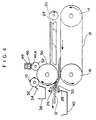
Fig. 4 is a schematic view showing a structure of an image
stripping apparatus according to a third embodiment of the
present invention.
Fig. 5 is a schematic view showing a structure of an image
forming and stripping apparatus according to a fourth
embodiment of the present invention.
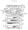
Fig. 6 is a schematic view showing a structure of an image
forming and stripping apparatus according to a fifth embodiment
of the present invention.
Fig. 7 is a schematic view of a structure of a fixing and
stripping unit used in the image forming and stripping apparatus
of Fig. 5 or 6, and illustrates a state in which a fixing mode
is selected.
Fig. 8 is an operational view showing a state of a fixing
and stripping unit of Fig. 7 at a time when a stripping mode
has been selected.
Fig. 9 is a schematic view of a structure of a fixing and
stripping unit according to a sixth embodiment and used in the
image forming and stripping apparatus of Fig. 5 or 6, and
illustrates a state in which a stripping mode has been selected.
Fig. 10 is a schematic view of a structure of a fixing
and stripping unit according to a seventh embodiment and used
in the image forming and stripping apparatus of Fig. 5 or 6,
and illustrates a state in which a stripping mode is selected.
Fig. 11 is a schematic view showing a structure of an image
forming and stripping apparatus according to a eighth
embodiment in which a stripping liquid applying unit is
provided.
Fig. 12 is a schematic view showing the stripping liquid
applying unit used in the image forming and stripping apparatus
of Fig. 11, at a time when a fixing mode has been selected.
Fig. 13 is an operational view showing a state of the
stripping liquid applying unit of Fig. 12, at a time when a
stripping mode has been selected.
DESCRIPTION OF THE PREFERRED EMBODIMENTS
The present invention will be described in detail
hereinafter.
An image stripping member of the present invention is not
specifically limited and can be any material in so far as it
has a layer on a substrate, and a material forming the surface
layer of the layer has affinity and releasability with respect
to an image forming material or an image recording material of
an image recording medium, and in regard to the affinity and
releasability with respect to the image recording material, the
affinity may independently be imparted by an affinitive
material and the releasability may independently be imparted
by a releasing material or the affinity and releasability may
be imparted by a material having both properties.
From the viewpoint of ease of material designing, the
material forming the surface layer preferably contains a
releasing material and an affinitive material, but if
homogeneous mixing of the releasing material and the affinitive
material is difficult, a material having both affinity and
releasability is preferably contained.
Examples of substrates for the image stripping member of
the present invention include: various kinds of heat resistant
metals, such as aluminum, nickel, platinum, zinc, copper, iron,
stainless steel and the like; alloys of these metals and these
metals with the surfaces thereof subjected to an oxidation
treatment; and sintered products of aluminum oxide, titanium
oxide, zirconium oxide, calcium phosphate, barium titanate or
the like. Heat resistant resin films such as of polyimide,
polyamide, polycarbonate, polyphenylene sulfide, polyethylene
phthalate and the like can also be effectively used.
The material forming the surface layer of the image
stripping member may be either a liquid material or a solid
material, but a solid material is more preferably used in
consideration of being able to be used without mobility in a
stable manner. The liquid material and the solid material can
be used together in combination.
A releasing material used in the surface layer of an image
stripping member of the present invention is not specifically
limited and may be any material in so as far as it has
releasability with respect to an image forming material and an
image recording material. More specifically, examples include:
a fluorine compound, wax, a silicon compound and the like, and
they may be used alone or in combination.
Among these materials, silicon compounds are preferable
in consideration of compatibility with affinitive materials and
safety.
Examples of fluorine compounds include: fluorine-based
polymers, fluorine-based oils and the like.
Specific examples of fluorine-based polymers include:
a polymer and a copolymer synthesized from a fluorine
containing-monomer such as vinylidene fluoride,
trifluoroethylene, chlorotrifluroethylene,
tetrafluoroethylene, pentafluoropropylene,
hexafluoropropylene or the like; a copolymer synthesized from
the above fluorine-containing monomer and ethylene,
(perfluoro)alkenyl vinyl ether or acrylic resin; and a polymer
having a perfluoroaliphatic ring structure such as a polymer
produced by cyclic polermerization of perfluoroalkenyl vinyl
ether or the like. Moreover, a material which is manufactured
as an elastomer (rubber) from the above mentioned polymer, a
fluorine-based oil or the like can be used as well.
Examples of fluorine-based oils include:
perfluoropolyethers represented by X-CF2(OC2F4)p(OCH2)qOCF2-X;
and more specifically, an isocyanate-modified
perfluoropolyether in which X is OCN-C6H3(CH3)NHCO-, a
carboxyl-modified perfluoropolyether in which X is -COOH, an
alcohol-modified perfluoropolyether in which X is -CH2OH or
-CF2CH2(OCH2CH2)nOH, and a ester-modified perfluoropolyether in
which X is -COOR and the like.
Examples of waxes include: a polyethylene wax with a low
molecular weight, an oxygen convertible polyethylene wax with
a low molecular weight, a polypropylene wax with a low molecular
weight, an oxygen convertible polypropylene wax with a low
molecular weight, a higher fatty acid wax, a higher fatty acid
ester wax, sazole wax, carbauna wax, bees wax, montan wax, a
paraffin wax, a micro-crystalline wax and the like.
Examples of silicon compounds include: organic silicon
compounds, silicone rubbers, silicone resins, silicone oils and
the like. Examples of organic silicon compounds include:
silane compounds, fluorine-containing silane compounds, and
isocyanate silane compounds.
Examples of silane compounds include: alkoxy silanes,
such as Si(OCH3)4, CH3Si(OCH3)3, (2H3)2Si(OCH3)2, C6H5Si(OCH3)3,
Si(OC2H5)4, CH3Si(OC2H3)3, (CH3)2Si(OC2H5)2, C6H5Si(OC2H5)3,
(CH3)2CHCH2Si(OCH3)2, silazanes such as (CH3)3SiNHSi(CH3)2,
special silylating agents, such as ((CH3)SiNH)2CO, tert-C4H9(CH3)2SiCl
and the like, silane coupling agents, silane
compounds, such as HSC3H6Si(OCH)3, and hydrolysates and partial
condensates of the above mentioned compounds. Examples of
silane coupling agents include: vinylsilanes such as
vinyltrichlorosilane, vinyltris(β-methoxyethoxy)silane,
vinyltriethoxysilane, vinyltrimethoxysilane and the like;
acrylic silanes, such as
γ-methacryloxypropyltrimethoxysilane; epoxysilane, such as
β-(3, 4-epoxycyclohexyl)ethyltrimethoxysilane,
γ-glycidoxypropyltrimethoxysilane,
γ-glycidoxypropylmethyldiethoxysilane and the like; and
aminosilanes, such as N-β-(aminoethyl) γ-aminopropylmethoxysilane,
N-β-(aminoethyl) γ-aminopropylmethyldimethoxysilane,
γ-aminopropyltriethoxysilane, N-phenyl-γ-aminopropyltrimetoxysilane
and the like.
As fluorine-containing silane compounds, fluorine-containing
silicon compounds containing a perfluoroalkyl group
are preferably used in order to improve releasability, and
specific examples thereof include: C6F13C2H4Si(OCH3)3,
C7F15CONH(CH2)3Si(OC2H5)3, C8F17C2H4Si(OCH3)3, C8F17C2H4SiCH3(OCH3)2,
C8F17C2H4Si(ON=C(CH3)(C2H5))3, C9F19C2H4Si(OCH3)3,
C9F19C2H4Si(NCO)3, (NCO)3SiC2H4C6F12C2H4Si(NCO)3,
C9F19C2H4Si(C2H5)(OCH3)2, (CH3O)3SiC2H4C8F16C2H4Si(OCH3)3,
(CH3O)2(CH3)SiC9F18C2H4Si(CH3)(CH3O)2 and the like; and
hydrolysates and partial condensates and the like.
Examples of isocyanate silane compounds include:
(CH3)3SiNCO, (CH3)2Si(NCO)2, CH3Si(NCO)3,
vinylsilyltriisocyanate, C6H5Si(NCO)3, Si(NCO)4, C2H5OSi(NCO)3,
C8H17Si(NCO)3, C18H37Si(NCO)3, (NCO)3SiC2H4Si(NCO)3 and the like.
Silicone rubber can be classified into a mirrorable type
and a liquid type. Mirrorable type silicon rubbers include
silicone rubbers which are produced in such a manner that a
linear polyorganosiloxane with a high degree of polymerization,
such as a dimethyl type, a methylvinyl type, a methylphenylvinyl
type, a methylfluoroalkyl type or the like is used as the main
material, and reinforcing filler and a variety of other
additives are mixed thereinto, and the thus prepared composites
are cured by heating after addition of a vulcanizing agent.
Types of liquid silicone rubbers include: a condensation type
silicone rubber which is cured at room temperature, an addition
type silicone rubber which is cured by heating in the presence
of a platinum type catalyst, an ultraviolet curable type
silicone rubber, and the like. Further, another example is a
silicone rubber which is produced as an elastomer from the above
mentioned silane compound.
Types of silicone resins include: a silicone resin
produced by polymerization of the above silane compound, a
curable type silicone resin, and the like. A curable silicone
resin can be synthesized by condensation of silanols obtained
by hydrolysis of a chlorosilane having three or more functional
groups or a mixture thereof with a chlorosilane having one or
two functional groups to form a polysiloxane, and a condensation
reaction (curing reaction) is further carried out by use of a
metal salt of an organic acid or an amine as a catalyst to obtain
the curable type silicone resin. From the viewpoint of the
curing reaction, a silicone resin, which is curable upon
exposure to humidity or heat or an energy ray such as light,
an electron beam or the like, is preferred.
Examples of silicone oils include: silicone oils of a
dimethylpolysiloxane or methylphenylpolysiloxane type; a
methylhydrogensilicone oil; and a reactive silicone oil into
which a reactive group is introduced. Examples of reactive
silicone oils include: amino-modified silicone oils, epoxy-modified
silicone oils, carboxyl-modified silicone oils,
carbinol-modified silicone oils, methacrylic-modified
silicone oils, mercapto-modified silicone oils, phenol-modified
silicone oils, fluorine-modified silicone oils and the
like. If these silicone oils are used in a mixture with an above
mentioned silane compound, releasability of an image stripping
member is markedly improved.
While the content ratio of the releasing material in the
surface layer of the image stripping member is dependent on the
types of releasing materials and the types of affinitive
materials used together with the releasing material, it is
preferably in the range of 5 to 80 % by weight, or more preferably
in the range of 25 to 70 % by weight. If the content ratio of
the releasing material in the surface layer is less than 5 %
by weight, the action of the adhesive agent is stronger and the
image recording medium is thereby adhered in a winding manner
to the image stripping member, so that an image forming material
transferred to the image stripping member cannot be removed from
the image stripping member and the image forming material is
accumulated on the surface of the image stripping member and
thus the original releasability cannot be maintained, even
though the winding manner can be avoided. On the other hand,
if the content ratio exceeds 80 % by weight, the releasability
is stronger, and thus the image forming material cannot be
removed from the image recording medium.
The releasing materials of the present invention may be
used singly or in combination.
If the releasing material as described above is
incorporated into a material forming the surface layer of the
image stripping member, the adhesion of the image recording
medium on the image stripping member can be greatly improved.
The affinitive material used in the surface layer of the
image stripping member of the present invention is not
specifically limited and can be any material having affinity
and compatibility with the image forming material of the image
recording medium and the like. For example, color toners
fundamentally comprise yellow, magenta and cyan, i.e., the
three primary colors, and a variety of colors is reproduced by
using the three types of toners. For this reason, in general,
when three types of toners are used, toner layers equivalent
to two more colors are overlapped and built up more than the
black toner. In order to fix the color toner layers, it is
necessary that either a temperature of a heating heater is
raised or a fusing temperature of the toners is lowered. However,
in the former case, there are problems with regard to safety
and in that there is an increase in energy consumption.
Therefore, the physical properties of a color toner, such as
thermal responsiveness and the like, are made to vary in
accordance with types of image forming materials, for example,
in such a manner that the color toner is made of a material which
is fusible at a lower temperature, compared with that of a black
toner used in a regular monochromatic copier. Thus, an
affinitive material suitable for peeling respective image
recording materials must be selected.
Affinity and compatibility with an image forming material
can be evaluated by, for example, a solubility parameter (SP
value), which is derived from a partial structural unit of a
chemical structural formula. As SP values of materials are
closer to each other, that is, as chemical structures are more
similar to each other, the materials have higher affinity and
compatibility.
Therefore, as an affinitive material of the present
invention, an affinitive material having an SP value within the
range of ± 1.0 of an SP value of the image forming material to
be used can suitably be used. More specifically, an affinitive
material having an SP value in the range of 8.0 to 12.0
(cal/cm3)1/2 can suitably be used.
As an affinitive material of the present invention, a
material which exhibits a thermal fusing property similar to
the image forming material is preferred. A thermally-fusible
material having a fusing temperature in the range from a
temperature which is 20°C lower than the fusing point of the
image forming material to a temperature which is 50°C higher
than the fusing temperature thereof is more preferable. Among
materials showing such a property, the same resin as a resin
used in the image forming material is particularly preferable.
Specifically, the affinitive materials include:
styrene-based resins such as a polymer or copolymer of styrene
or parachlorostyrene or the like; vinyl-based resins such as
a polymer or copolymer of methyacrylate, methyl methacrylate
or the like; olefin-based resins, such as a polymer or copolymer
of ethylene or propylene; thermoplastic resins such as epoxy
resins; polyester resins; polyurethane resins, polyamide
resins, polyether resins, polyacetal resins, polycarbonate
resins, cellulose resins and the like.
The thermally-fusible material of the present invention
is preferably homogeneously mixed with a releasing material.
In order to mix homogeneously, a compatibilizing agent for the
thermally-fusible material and the releasing material, or a
plasticizer, can be added.
As a compatibilizing agent for the thermally-fusible
material and the releasing material, known compatibilizing
agents can be used. A copolymer of the monomer forming the
thermally-fusible material and the monomer forming the
releasing material can preferably be used, or a copolymer of
the monomer forming the thermally-fusible material, the monomer
forming the releasing material, and a monomer having good
compatibility therewith can preferably used. A material which
is obtained by allowing the monomer forming the releasing
material or a reactive releasing material to react with the
thermally-fusible material or by allowing the monomer forming
the thermally-fusible material to react with a releasing
material or the like is also preferred.
A blending ratio of the compatibilizing agent is not
specifically restricted, in so far as affinity, compatibility,
releasability and the like between the image stripping member
and the image forming material do not change the surface
characteristics of the image stripping member, but the ratio
is preferably in the range of 1% by weight to 30% by weight with
respect to the total amount of the thermally-fusible material
and the releasing material.
As a plasticizer of the present invention, known
plasticizers can be used. Examples of plasticizers include:
di-ester phthalate, such as dioctyl phthalate, di-(2-ethylhexyl)phthalate,
dinonylphthalate, dilaurylphthalate,
dibutyllaurylphthalate, dibutylbenzylphthalate; aliphatic
dibasic acid esters, such as di(2-ethylhexyl) adipate, di
(2-ethylhexyl) sebacate and the like; triester phosphates, such
as tricresylphosphate, tri(2-ethylhexyl)phosphate and the
like; polyethyleneglycol; epoxy aliphatic acid esters and the
like.
The blending ratio of the plasticizer is not specifically
restricted provided that affinity, compatibility,
releasability and the like between the image stripping member
and the image forming material do not change the surface
characteristics of the image stripping member, but the ratio
is preferably in the range of 1% by weight to 30% by weight with
respect to the total amount of the thermally-fusible material
and the releasing material.
However, in light of operability and the like of the image
stripping apparatus, it is preferred that one or several kinds
of image stripping members are used for both color toners for
color copiers and black toner for monochromatic copiers. Taking
into account the melting point of a toner, it is preferable that
affinity and compatibility with an image forming material is
maintained over a wide range of temperatures. Such affinitive
materials include pressure sensitive adhesives.
Examples of pressure sensitive adhesives include a
rubber-based adhesive, an acrylic-based adhesive, a vinyl ether
polymer based-adhesive, and a silicone adhesive. Among these,
a silicone adhesive is preferable, because it has a heat
resistance such that it can be used at a temperature at which
an image forming material is fused by heating, it has good
compatibility with a silicone compound as a releasing material,
and peelability and releasability can be maintained over a long
period of time in repeated use.
Other affinitive materials which can be effectively used
include, for example, a variety of metals, resins and the like
having a sufficient heat resistance for use as a substrate for
an image stripping member.
Affinitive materials of the present invention may be used
singly or in combination.
Materials having releasability and affinity used in the
surface layer of the image stripping member of the present
invention are not specifically limited provided that each is
a single material and has affinity and releasability with
respect to the image forming material and the image recording
material of the image recording medium. For example, a resin
containing a component which imparts releasability can be used.
As components which impart releasability in the present
invention, the above-described releasing material can be used.
An alkyl succinic acid, an anhydride thereof or an ester thereof,
or an alkenyl succinic acid, an anhydride thereof or an ester
thereof can preferably be used since these compounds can
synthesize a copolymer with a resin material having high
affinity with an image forming material.
Resins containing a component which imparts
releasability of the present invention are resins which are
obtained by polymerizing the above components which impart
releasability. The resins comprise a block copolymer and a graft
copolymer.
Preferred examples of resins containing a component
imparting releasability of the present invention include:
resins containing in their structures a component imparting
releasability, the resins being exemplified by affinitive
materials, such as styrene base copolymers, ethylene base
copolymers, polyester base copolymers, acrylic base copolymers
or the like. Especially preferable among such resins are
polyester base resins which exhibit good adhesiveness with,
especially, image forming materials and contain in the
structure thereof a component imparting releasability.
When a resin which contains a releasability-imparting
component is used, singly or in combination, as the material
forming the surface layer, the content ratio of the
releasability-imparting component is in the range of 7 to 25%
by mol of the total quantity of the monomer. If the content is
less than 7% by mol, it is difficult for the releasability effect
to be exhibited. If the content is more than 25% by mol, the
melting point of the polyester resin is too low and adhesiveness
is exhibited when the releasing material is heated and used,
so that the releasability effect with an image recording medium
is lost. In this case, while a releasing solid material can
further be added in order to suppress loss of the releasability
effect, the image stripping function, which is originally
sought, deteriorates.
The surface layer of the image stripping member of the
present invention is formed by applying onto a substrate the
above mentioned material as a solution or a dispersion in a
liquid state. The following are examples of generally-used
methods for applying or permeating the solution or the like:
a blade coating method, a wire bar coating method, a spray
coating method, a dip coating method, a bead coating method,
an air-knife coating method, a curtain coating method, a roll
coating method and the like.
The coated film may be dried by air. However, if drying
by heat is carried out, the releasability with respect to the
image forming material increases even more. The reason for this
is not known for certain, but is suspected to be due to the
arranging or orienting of the components reacting with the
substrate. Any of known methods, such as placing the coated
image stripping member into an oven, passing the image stripping
member through an oven, or the like may be used as the method
for heat drying.
In the image stripping member of the present invention,
instead of providing the surface layer containing the releasing
material, a plurality of holes may be formed uniformly in the
surface layer formed of the affinitive material, and the
releasing material may be filled in the holes.
There are surface irregularities (depressions and
protrusions) of the recording member which are formed by the
image forming material. The maximum size is in the range of 20
to 30 µm. When the image stripping member and the image recording
medium are brought into contact with one another, the surface
layer of the image stripping member can be made to closely
contact the image forming material if the surface layer has
fluidity. However, there is sometimes a microscopically small
amount of air between the surface of the image stripping member
and the image forming material, resulting in insufficient
contact. In order to improve the degree of closeness in contact
by formation of local pressure, there preferably are surface
irregularities of several µm on the surface of the image
stripping member. Fine particles are added in the surface layer
for this reason.
The shapes of the fine particles are not particularly
limited, and, for example, a sphere, a thin plate having an
elliptical shape in plan view, a doughnut-like shape, a cube,
an irregular shape, or the like may be used. The particle size
is preferably in the range of 0.5µm to 50µm in diameter or a
length in a longitudinal direction, and more preferably in the
range of 1µm to 30µm.
Examples of materials used for the fine particles
include: titanium oxide, aluminum oxide, aluminum sulfate,
zirconium oxide, barium titanate, silica, talc, clay (kaolin),
calcium carbonate, silicone resin, acrylic resin, styrene resin,
styrene-acrylic resin, melamine resin, benzoguanamine resin,
melamine-benzoguanamine resin, polyolefin resin and the like.
In particular, fine particles of silicone resin, acrylic resin
or styrene resin are preferred.
If a resin material is used for the surface layer of the
image stripping member, there is the chance that, although the
surface layer works elastically, the elastic function will not
be sufficiently exhibited depending on the properties of the
resin or the thickness of the layer, and thus the image stripping
member cannot follow the surface irregularities of the image
recording medium. In such a case, to make the image stripping
member closely contact the surface irregularities of the image
recording medium, an elastic material is used as the substrate
of the image stripping member or an elastic layer is inserted
between the substrate and the surface layer. In consideration
of a case in which the image stripping member is used as a heating
medium, it is preferable that the material of the elastic layer
is heat resistant, and thus, silicone rubber, Teflon rubber or
the like is preferably used.
In the image stripping apparatus and the image stripping
method of the present invention, a known image recording medium,
in which a recording layer is formed on a substrate made of plain
paper, coated paper, metal, ceramic, a plastic film such as an
OHP film, or the like can be used. For example, image recording
media such as those described below can be used.
Examples of materials used for the substrate of the image
recording medium include: paper, metal (aluminum and the like),
plastics, and ceramics (alumina and the like). The shape of the
substrate is not particularly limited, but it is preferable that
the substrate is film-shaped.
In the case where paper is used as the substrate of the
image recording medium, examples of pulp which is a raw material
for paper are virgin bleached chemical pulps manufactured by
chemically treating wood and other fibrous raw materials and
being subjected to a bleaching step, the raw material being,
for example, hard wood bleached craft pulp, hard wood unbleached
craft pulp, hard wood bleached sulfite pulp, soft wood bleached
craft pulp, soft wood unbleached craft pulp, soft wood bleached
sulfite pulp and soda pulp and the like. Among these, pulp having
a higher whiteness is preferred as a raw material for the
substrate. Examples of waste paper pulp include waste paper
pulp obtained by dissociating unprinted papers of the most
whiteness, special whiteness or medium whiteness, and other
unprinted waste paper discarded at a book-binding and printing
factories and cutting shops; and waste paper pulp obtained by
dissociating various kinds of waste paper and deinking them with
respectively proper methods, the waste paper being high quality
paper, high quality coated paper, medium quality paper, medium
quality coated paper, ground wood paper and the like printed
by planographic, letterpress, or intaglio printings, or
electrophotographic, thermal sensitive, thermal transfer,
pressure sensitive, ink jet recording systems, carbon paper or
the like and paper hand-written with water soluble or oily ink,
or pencil, or newspaper and the like. Among such pulp, waste
paper pulp having high whiteness and a low amount of mixed
foreign matter is preferred.
As the image recording medium, preferred is an image
recording medium whose surface layer is made of a material
having releasability with respect to an image recording
material. For example, it is also preferred that a releasing
material having good releasability with respect to an image
forming material is applied on or made to penetrate into the
pulp fiber surface of an image recording paper or, if paper is
coated, the surface of coated paper, to impart releasability
to the substrate surface.
Examples of releasing materials include fluorine-based
compounds such as fluorine-based oils, silicon compounds, waxes
and the like. However, in consideration of releasability with
respect to an image forming material, transferability to
members or materials in the apparatus from the substrate surface,
traveling of paper and the like, materials which directly bond
with pulp fibers by reacting with the pulp fibers are preferred.
As releasing materials which directly bond with pulp fibers by
reacting with them, silicon compounds are preferred.
The above mentioned compounds can be used as the silicon
compounds. These silicon compounds can be used singly or in
combination. Other silicon compounds which may be used are
silica gel and the like. Among the above mentioned silicon
compounds, the following compounds are preferred: fluorine-containing
silicon compounds, isocyanate silane compounds,
modified silicone oils having a reactive group in the molecule,
or mixtures thereof. These silicon compounds are coated on the
substrate of the image recording medium or the substrate is
dipped in a solution thereof and thereafter dried, so that a
coated film having releasability is formed.
When paper is used as the substrate for the image
recording medium, in order to improve the fixability to the
image forming material, it is preferable that a proper degree
of surface irregularity is imparted to the surface of the image
recording medium by further adding fine particles to the image
recording medium. Thus, since a sufficient fixing force can
be obtained merely by allowing an image forming material to
stick to substrate fibers or to stick to substrate fibers by
enveloping them, the amount of resin used in the image forming
material can be reduced. Examples of fine particles include:
talc, clay (kaolin), calcium carbonate, titanium oxide,
aluminum oxide, aluminum sulfate, zirconium oxide, barium
titanate, silica, silicone resin, acrylic resin, styrene resin,
styrene-acrylic resin, melamine resin, benzoguanamine resin,
melamine-benzoguanamine resin and the like. If a fluorine-containing
silicon compound, an isocyanate silane compound, a
modified silicone oil or the like, which are highly reactive
with these fine particles, is used as the releasing material,
the releasing material is hardened together with pulp fibers,
so that a function of fixing fine particles in the substrate
is also exhibited.
An aluminum compound, a titanium compound or a zirconium
compound can be added to the coating composition for coating
the releasing material on the substrate of the image recording
medium in an amount such that the releasing effect thereof does
not deteriorate. Examples of such compounds include: aluminum
isopropylate, aluminum sec-butylate, aluminum tert-butylate,
tetraisopropyl titanate, tetra n-butyl titanate,
tetraisobutyl titanate, tetra sec-butyl titanate, tetra
tert-butyl titanate, tetra n-pentyl titanate, tetraisopentyl
titanate, tetra n-hexyl titanate, tetra n-heptyl titanate,
tetra n-octyl titanate, tetraisooctyl titanate, tetra n-nonyl
titanate, tetramethyl zirconate, tetraethyl zirconate,
tetraisopropyl zirconate, tetra n-propyl zirconate, tetra
n-butyl zirconate, tetraisobutyl zirconate, tetra tert-butyl
zirconate, mono sec-buthoxy aluminum di-isopropylate,
ethylacetoacetate aluminum di-isopropylate, di-n-butoxy
aluminum monoethylacetoacetate, aluminum di-n-butoxide
methylacetoacetate, aluminum di-isobutoxide
monomethylacetoacetate, aluminum di-sec-butoxide
monoethylacetoacetate, aluminum di-isopropoxide
monoethylacetoacetate, aluminum tris-acetyl acetoacetate,
aluminum di-isopropoxide monoacetylacetonate, aluminum
monoacetylacetonate bis(ethylacetoacetate), aluminum tris-(ethylacetoacetate),
cyclic aluminum oxide acylate, di-isopropoxy
titan bis(acetylacetonate), di-n-butoxy titan-bis-(acetylacetonate),
tetraoctylene glycol titanate,
tetrakisacetylacetone zirconium and the like.
Examples of light transmissive plastic films which can
be used as a substrate for an OHP film are: an acetate film,
a cellulose triacetate film, a nylon film, a polyester film,
a polycarbonate film, a polystyrene film, a polyphenylene
sulfide film, a polypropylene film, a polyimide film,
cellophane and the like. Currently, a polyester film,
particularly, a biaxially stretched polyethylene
terephthalate film is often used from the comprehensive
viewpoint of mechanical, electrical, physical, chemical
properties, processability, and the like.
It is preferable to provide the surface of the above
mentioned plastic film with releasability, as in the case of
the paper substrate. It is preferable to use the
previously-described releasing materials as the releasing
material for this purpose, although the releasing material in
this case as well is not limited to those described previously.
The following generally used methods are used as methods
for applying or permeating the solution or the like: a blade
coating method, a wire bar coating method, a spray coating
method, a dip coating method, a bead coating method, an
air-knife coating method, a curtain coating method, a roll
coating method and the like.
The coated film may be dried by air drying, but heat drying
has an advantage in that the releasability with respect to the
image forming material is increased. Although the exact reason
is unknown, it is believed that a component which reacts with
a substrate is arranged or oriented. Any of well-known methods
may be used as the heat drying method, such as the coated image
recording medium being inserted in or made to pass through an
oven, the coated image recording medium being made to contact
a heated roller, or the like.
The image stripping method using the above-described
image stripping member comprises the steps of: stripping an
image forming material from an image recording medium by making
an image stripping member contact the image forming material
on the image recording medium and heating the image recording
medium, the image stripping member having a surface layer having
affinity and releasability with respect to an image recording
material; and removing, from the image stripping member, the
image forming material which has been transferred to the image
stripping member from the image recording medium.
The method can further comprise the step of reducing
adhesiveness with respect to the image recording medium and
image forming material, before contacting the image stripping
member with the image forming material on the image recording
medium. In the step of reducing the adhesiveness, it is
preferred that the image forming material on the image recording
medium is fused. To this end, the image forming material can
be heated or exposed to infrared radiation or the like. As an
alternative, the image recording medium on which the image
forming material is held may be dipped in a solution containing
a surfactant or the like. From the viewpoint of maintaining
releasability of the image stripping member, the surfactant
should not be accumulated on the image stripping member.
Therefore, adoption of a method for reducing adhesiveness by
means of heating or infrared irradiation is preferable.
Heating of the image forming material can be conducted
in the stripping step.
An image stripping apparatus according to the first
embodiment, to which the above image stripping member and image
stripping method are applied, is shown in Figs. 1 and 2.
The image stripping apparatus of Figs. 1 and 2 used for
stripping an image forming material 10 from an image recording
medium 12 comprises a conveying roller 14 and a pressure roller
16, both of which are substantially the same size and disposed
horizontally. A conveying belt 18 is trained about the conveying
roller 14 and pressure roller 16. A second conveying roller
20 is disposed directly above the first conveying roller 14 so
as to be spaced apart from the first conveying roller 14 by a
predetermined distance. A stripping roller 22 is disposed
directly above the pressure roller 16 so as to be spaced apart
from the pressure roller 16 by a predetermined distance. The
stripping roller 22 serves as an image stripping member whose
surface layer is made of a material having affinity and
releasability with respect to an image recording material. When
the image recording medium 12 passes a nip section between the
pressure roller 16 and the stripping roller 22, pressure is
applied to the image recording medium 12. A heater 24 is
disposed at a position which is between the second conveying
roller 20 and the stripping roller 22 and which is above and
along the conveying belt 18.
A pair of conveying rollers 26, 28 each having a small
diameter are disposed, one above the other, on the side of the
stripping roller 22 opposite the side at which the conveying
roller 20 is disposed. A strip finger 30 is disposed between
the upper conveying roller 26 and the stripping roller 22, and
is used for stripping the image forming material 10 in a fused
state from the image recording medium 12. The strip finger 30
is substantially plate-shaped. An end portion of the strip
finger 30 at the stripping roller 22 side thereof becomes
thinner toward the tip end thereof. This tip end of the strip
finger 30 is disposed at a position which is higher than the
lowest part of the stripping roller 22 and which is spaced apart
from the outer periphery of the stripping roller 22 with slight
gap therebetween. The other end of the strip finger 30 is
disposed at a position in the vicinity of the nip section between
the rollers 26, 28.
On the conveying roller 20 side of the highest part of
the stripping roller 22, a cleaning roller 32, which has a
surface layer formed by a material having high affinity with
the image forming material 10, is disposed so as to contact the
stripping roller 22. Moreover, a cleaning blade 34 is disposed
on the conveying roller 20 side of the cleaning roller 32. The
cleaning blade 34 is plate-shaped, and an end thereof contacts
the outer periphery of the cleaning roller 32 along an axial
direction thereof. The other end of the cleaning blade 34 is
upwardly disposed in an oblique manner.
Under the cleaning blade 34, a recovery box 36 for
recovering the image forming material 10 is disposed. A thermal
insulator 38 which is plate-shaped is interposed between the
recovery box 36 and the heater 24 for intercepting heat from
the heater 24.
A recovery tray 40, for recovering the image recording
medium 12 from which the image forming material 10 has been
removed, is disposed at a position lower than the conveying
rollers 26, 28 at the side thereof opposite the stripping roller
22.
In the image stripping apparatus, the first conveying
roller 14 and pressure roller 16 are driven to be rotated in
a counterclockwise direction at the same circumferential speed.
The second conveying roller 20 and the stripping roller 22 are
both driven to be rotated in the forward direction relative to
the rotational direction of the conveying roller 14 and pressure
roller 16, that is, in the clockwise direction. The conveying
roller 28 is driven to be rotated in counterclockwise direction,
and the conveying roller 26 is driven to be rotated in a forward
direction relative to the rotational direction of the conveying
roller 28, that is, in a clockwise direction.
Operation of the image stripping apparatus will be
described hereinafter.
As shown in Fig. 1, the image recording medium 12 is guided
to the nip section between the first and second conveying
rollers 14, 20 in a state in which the surface of the image
recording medium 12 on which the image forming material 10 is
held faces upward. The image recording medium 12 is moved toward
the pressure roller 16 by movement of the conveying belt 18
caused by rotation of the conveying rollers 14, 20, the
conveying roller 14, and the pressure roller 16. The image
forming material 10 on the image recording medium 12 is fused
by heat radiated from the heater 24 which is disposed above the
conveying belt 18 and heated in advance.
As shown in Fig. 2, the image recording medium 12 is guided
to the nip section between the pressure roller 16 and the
stripping roller 22 and moved in accordance with the rotation
of these rollers, and the stripping roller 22 and the image
forming material 10 on the upper surface of the image recording
medium 12 contact each other. At this time, since the image
forming material 10 is in a fused state and the surface layer
of the stripping roller 22 contains a material having high
affinity with respect to the image forming material 10, the
image forming material 10 adheres to the stripping roller 22,
and the image recording medium 12 adheres to the stripping
roller 22 with the image forming material 10 being interposed
therebetween.
Here, since the image forming material 10 is generally
held in at image region other than edge portions of the image
recording medium 12 and is not held at the leading end portion
of the image recording medium 12 which is a non-image region,
the leading end portion does not adhere to the stripping roller
22. For this reason, a gap is formed between the leading end
portion of the image recording medium 12 and the outer periphery
of the stripping roller 22 as the stripping roller 22 is rotated
in the clockwise direction, after the leading end portion of
the image recording medium 12 passes the lowest point of the
stripping roller 22. The leading end portion of the image
recording medium 12 abuts the lower surface of the strip finger
30. The image recording medium 12 is guided along the lower
surface of the strip finger 30 to the nip section between the
rollers 26, 28. Since a material having high affinity with
respect to the image forming material 10 is contained in the
surface layer of the stripping roller 22, the image forming
material 10 is left behind on the outer periphery of the
stripping roller 22 and stripped from the image recording medium
12 when the image recording medium 12 is separated from the
stripping roller 22.
Since a gap is formed between the strip finger 30 and the
stripping roller 22, the image forming material 10 transferred
to the stripping roller 22 from the image recording medium 12
does not remain at the tip end of the strip finger 30, and as
the stripping roller 22 rotates, the image recording material
10 passes through the gap, reaches the nip section between the
stripping roller 22 and the cleaning roller 32, and contacts
the cleaning roller 32 so as to adhere thereto.
A material having high affinity with respect to the image
forming material 10 is contained in the surface layer of the
cleaning roller 32, and the material forming the surface layer
of the stripping roller 22 has not only affinity but also
releaseability with respect to the image recording material.
Therefore, the image forming material 10 is transferred to the
cleaning roller 32 from the stripping roller 22 as the stripping
roller 22 and the cleaning roller 32 rotate. In this way, since
the image forming material 10 transferred to the stripping
roller 22 is stripped with ease from the stripping roller 22,
the stripping roller 22 maintains the same level of
releasability as it had at the initial stages.
The image forming material 10 transferred to the cleaning
roller 32 reaches the lower surface of the end portion of the
cleaning blade 34 in contact with the outer periphery of the
cleaning roller 32 by rotation of the cleaning roller 32 in a
counterclockwise direction in accordance with the rotation of
the stripping roller 22. The image forming material 10 is
stripped from the cleaning roller 32 by the cleaning blade 34.
The stripped image forming material 10 falls downward of
the cleaning blade 34 to be accumulated in the recovery box 36.
Since the recovery box 36 is shielded from heat radiated from
the heater 24 by the thermal insulator 38, the image forming
material 10 is cooled in the recovery box 36 and solidified,
or the image forming material 10 before recovery in the recovery
box 36 is prevented from being fused again.
The image recording medium 12 from which the image forming
material 10 has been removed is moved in accordance with the
rotation of the conveying rollers 26, 28 and is recovered in
the recovery tray 40.
In the first embodiment, if there is the concern that the
image forming material 10 will solidify before being
transferred to the cleaning roller 32, the stripping roller 22
is preferably heated.
In Fig. 3, a second embodiment of the image stripping
apparatus of the present invention is shown. The same
structures as those of the first embodiment are indicated by
the same reference numerals, and description thereof is
omitted.
An image stripping apparatus according to the second
embodiment comprises a pair of rollers 42, 44, which are
disposed one above the other at the side of the conveying roller
14 opposite the side at which the stripping roller 22 is disposed,
and a tank 46 disposed above an upper roller 42. The roller
42 is driven to be rotated in the clockwise direction. The tank
46 is in the shape of a box, and a length thereof along a direction
parallel to the axial direction of the roller 42 is
substantially the same as that of the roller 42. A slit (not
shown) is formed in the bottom wall of the tank 46 along a
direction parallel to the axial direction of the roller 42. A
sponge 46A is placed in the slit, and the lower surface of the
sponge 46A contacts the outer periphery of the roller 42. The
tank 46 contains a releasing material 48. The image stripping
apparatus does not include the cleaning roller 32. An end of
the cleaning blade 34 contacts the outer periphery of the
stripping roller 22 along the axial direction of the stripping
roller 22 at the conveying roller 20 side of the uppermost part
of the stripping roller 22. The other end of the cleaning blade
34 is disposed so as to incline downwardly.
In the image stripping apparatus, the releasing material
48 in the tank 46 is transferred to the outer periphery of the
roller 42 through the sponge 46A, and then made to adhere to
the image forming material 10 held on the image recording medium
12 guided to the nip section between the rollers 42, 44 in
accordance with the rotation of the rollers 42, 44. In the image
stripping apparatus, the image forming material 10 transferred
to the stripping roller 22 from the image recording medium 12
reaches the upper surface of the end portion of the cleaning
blade 34 which contacts the outer periphery of the stripping
roller 22, and is stripped from the stripping roller 22 by the
cleaning blade 34. The stripped image forming material 10 is
moved downward along the slope of the cleaning blade 34 to be
recovered in the recovery box 36.
It suffices for a roller which makes the releasing
material adhere to the image forming material 10 to only be
disposed at the side of the image recording medium 12 on which
the image forming material 10 is held. Therefore, it is possible
to provide a guide plate for guiding the image recording medium
12 to the nip section between the conveying rollers 14, 20
instead of the roller 44 which is omitted and bears no function
for the adhesion. In the present embodiment, while the releasing
material 48 is made to adhere to only one side of the image
recording medium 12, another tank may be provided on the roller
44 side and the releasing material 48 may thereby be made to
adhere to both sides of the image recording medium 12.
In Fig. 4, an image stripping apparatus of the present
invention according to the third embodiment is shown. The same
structures as those of the first and second embodiments are
indicated by the same reference numerals, and description
thereof is omitted.
Instead of the stripping roller 22 according to the first
embodiment, the image stripping apparatus according to the
third embodiment comprises a stripping roller 50 which is formed
of an aluminum with an anodic oxidation coat and whose surface
layer does not contain a material having releasability. Further,
the image stripping apparatus in accordance with the third
embodiment comprises no insulating material 38. In the image
stripping apparatus according to the third embodiment, the
cleaning roller 32 is disposed so that it contacts the stripping
roller 50 on the side of the uppermost part of the stripping
roller 50 opposite the side at which the conveying roller 20
is disposed. The cleaning blade 34 is disposed at the side of
the cleaning roller 32 opposite the side at which the conveying
roller 20 is disposed, in such a manner that an end of the
cleaning blade 34 contacts the outer periphery of the cleaning
roller 32 along the axial direction of the cleaning roller 32.
The other end of the cleaning blade 34 is inclined downwardly.
The recovery box 36 is disposed under the cleaning blade 34.
A roller 52 is disposed so that contacts the stripping roller
50 on the conveying roller 20 side of the uppermost portion of
the stripping roller 50. The tank 46 is disposed directly above
the roller 52 so that the sponge 46A embedded in the bottom wall
of the tank 46 contacts the outer periphery of the roller 52.
In this image stripping apparatus, the releasing material
48 is transferred to the outer periphery of the roller 52 via
the sponge 46A, then transferred to the outer periphery of the
roller 50, so that it is made to adhere to the image forming
material 10 held on the image recording medium 12 guided to the
nip section between the stripping roller 50 and pressure roller
16.
Since this image stripping apparatus can use an image
stripping member whose surface layer does not contain a material
having releasability, the apparatus can also be applied to cases
where the releasing material cannot homogeneously be dispersed
in the surface layer due to its poor compatibility with the
material having high affinity with respect to the image forming
material 10. In this case, the same effects are achieved as those
in the case where an image stripping member containing a
material having releasability in the surface layer is used.
The image stripping apparatus described above may be used
alone, or may be built into an electrophotographic image forming
apparatus or the like. As an example of such a case, Fig. 5
is a schematic view of an image forming and stripping apparatus
according to the fourth embodiment.
As illustrated in Fig. 5, the image forming and stripping
apparatus comprises a substantially box-shaped housing 60 and
a cover 62. A rectangular opening is formed in an upper wall
60A of the housing 60. A rectangular, transparent platen glass
(not shown) is fit into the opening. The cover 62 is rectangular,
is larger than the platen glass, is disposed so as to cover the
platen glass, and an end thereof is fixed by a hinge to the upper
wall 60A. The cover 62 can thereby be opened or closed. When
the cover 62 is closed, the cover covers the platen glass.
A photoreceptor 64 having a cylindrical shape, which is
driven to be rotatable in the clockwise direction, is disposed
in the housing 60. A charger 66, an exposing section 68, a
developing unit 70, a transfer belt 72, and a cleaner 76 are
disposed in the vicinity of the photoreceptor 64. The charger
66 is used for charging the photoreceptor 64. The exposing
section 68 for forming an electrostatic latent image by exposing
the photoreceptor 64 is disposed at a position downstream of
the charger 66 in the direction of rotation of the photoreceptor
64. The developing unit 70 for full color development, which
forms a visible image of respective colors by adhering the
image forming material on the electrostatic latent image on the
photoreceptor 64, is disposed at a position downstream of the
exposing section 68 in the rotational direction. The transfer
belt 72, which is cylindrical and transfers the visualized
latent image on the photoreceptor 64 onto the image recording
medium, is disposed downstream of the developing unit 70 in the
rotational direction. The cleaner 76 for removing residual
charge and residual image forming material on the photoreceptor
64 is disposed downstream of the transfer belt 72 in the
rotational direction.
An optical system control section 78 is provided in the
housing 60. The optical system control section 78 is provided
with an image reading section, which forms image data of each
color from an original, and one ROS (raster scanning device).
A laser beam 80 having a predetermined spot diameter is
illuminated toward the exposing section 68 in accordance with
the image data of the respective colors which image data is
output from the image reading section.
The developing unit 70 comprises a housing 82 in the shape
of a cylinder, and four slits (not shown) are formed on the outer
peripheral surface of the housing along the axial direction at
intervals of 90 degrees. A partition plate 84, having a shape
of a cross as viewed along a radial direction of the housing
82, is disposed so as to contact the inner wall of the housing
82 at a substantially central portion between adjacent slits.
The inner space of the housing 82 is divided into four equal
sections. A developing sleeve 86 having a cylindrical shape is
disposed in the vicinity of the slit of each partitioned inner
space. In each partitioned inner space, an image forming
material feeder and a stirring machine (both not shown) are
disposed. Moreover, image forming materials of black, cyan,
magenta and yellow are supplied to the partitioned inner spaces,
respectively. The developing unit 70 is intermittently driven
to be rotated and temporarily stopped at positions where the
respective slits are opposed to the photoreceptor 64, such that
the electrostatic latent image on the photoreceptor 64 is
developed with the image forming materials of the respective
colors.
The following members are disposed in the lower part of
the housing 60: a first tray 88 containing unused image
recording media; a second tray 90 containing image recording
media on which image forming materials are held; and a plurality
of pairs of rollers 92 for conveying the image recording media
from the first tray 88 and the second tray 90 to the transfer
belt 72.
The transfer belt 72 is driven to be rotated in the
counterclockwise direction. A transfer unit 94, which is used
for transferring an image forming material on the image
recording medium, is disposed at a position opposing to the
photoreceptor 64 and inside the transfer belt 72. A charger
96, which is used to charge the image recording medium and
facilitate separation of the image recording medium from the
transfer belt 72, is disposed downstream of the transfer unit
94 of the transfer belt 72 in a rotational direction. A finger
98 is disposed such that an end thereof contacts the transfer
belt 72 downstream of the charger 96 of the transfer belt 72.
A guide plate (not shown) for guiding the image recording medium
along the outer periphery of the transfer belt 72 is disposed
at the outer periphery of the transfer belt 72.
A conveying belt 100, for conveying an image recording
medium separated from the transfer belt 72, is disposed in a
vicinity of the finger 98. A pair of rollers 102 is disposed
at the side of the conveying belt 100 opposite the finger 98.
A slit is formed along a horizontal direction on a side wall
60B of the housing 60. A pair of rollers 104 are disposed in
the housing 60 in the vicinity of the slit. A third tray 106
extends upwardly from a lower position than the slit formed in
the side wall 60B. A fixing and stripping unit 108 is disposed
between the rollers 102, 104.
The image forming and stripping apparatus is controlled
by a control section (not shown) having a CPU and a memory. An
operation panel (not shown) for switching between fixing and
stripping modes is provided on the upper surface of the housing
60.
When a fixing mode is selected, the photoreceptor 64 is
charged in a uniform manner, is exposed in accordance with the
image data of the respective colors, and a latent image is
developed with an image forming material corresponding to image
data of one color to form a visible image of the one color. The
visible image is transferred onto an image recording medium
conveyed by the rollers 92 and the transfer belt 72 from the
first tray 88. Residual charge and residual image forming
material 10 on the photoreceptor 64 are removed by the cleaner
76. The above mentioned process is repeated for each color so
that a multi-color image is formed on the image recording medium.
Thereafter, the image recording medium is conveyed to the fixing
and stripping unit 108 by way of the transfer belt 100 and the
rollers 102, and the multi-color image is fixed on the image
recording medium. The image recording medium, on which the
multi-color image is fixed, is conveyed to the third tray 106
by the rollers 104.
On the other hand, when a stripping mode is selected, an
image recording medium holding an image forming material is
conveyed from the second tray 90 to the fixing and stripping
unit 108 by way of the rollers 92, the transfer belt 72, the
conveying belt 100, and the rollers 102, and the image forming
material is stripped from the image recording medium in this
unit. The image recording medium from which the image forming
material is stripped is further conveyed by the rollers 104 to
the third tray 106.
Fig. 6 shows an image forming and stripping apparatus for
a monochromatic or two color image. The same structures as
those of the fourth embodiment are respectively indicated by
the same reference numerals, and descriptions thereof are
omitted.
The image forming and stripping apparatus for a
monochromatic or two color image according to the fifth
embodiment comprises: instead of the optical system control
section 78, an optical system control section 110 including an
image reading section and two units of ROS for forming image
data for each color from an original; instead of the developing
unit 709, developing units 120, 122 equipped with developing
sleeves 116, 118 which each can develop only one color; and
instead of the transfer belt 72, the transfer unit 94 and the
charger 96, a transfer unit 124 disposed at a position between
the developing unit 122 and the transfer belt 100. Exposure can
therefore be conducted at two locations: at an exposing section
112 upstream of the developing unit 120 in the rotational
direction, and at an exposing section 114 at a position between
the developing units 120, 122.
In the image forming and stripping apparatus for a
monochromatic or two-color image, when a fixing mode is selected,
the photoreceptor 64 is charged in a uniform manner, is
subjected to exposure according to image data, and is developed
to form a monochromatic visible image on the photoreceptor 64.
When a two-color image is formed, the photoreceptor 64 is
further subjected to exposure according to another image data,
and is developed to form a two-color visible image on the
photoreceptor 64. The visible image is transferred to the
image recording medium conveyed from the first tray 88 by the
rollers 92. Residual electric charge and residual image
forming material 10 on the photoreceptor 64 are removed by the
cleaner 76. The transferred image recording medium is conveyed
to the fixing and stripping unit 108 by way of the conveying
belt 100 and the rollers 102 to fix a monochromatic or two-color
image on the image recording medium. The image recording
medium on which an image is fixed is conveyed to the third tray
106 by the rollers 104.
On the other hand, when a stripping mode is selected, the
image recording medium holding the image forming material is
conveyed to the fixing and stripping unit 108 from the second
tray 90 by way of the rollers 92, the conveying belt 100 and
the rollers 102, and the image forming material is stripped from
the image recording medium in this unit. The image recording
medium from which the image forming material is stripped is
further conveyed to the third tray 106 by the rollers 104.
Figs. 7 and 8 are schematic views of structures of a fixing
and stripping unit 108 used for the image forming and stripping
material according to the fourth and fifth embodiments. On the
roller 102 (Fig. 5 or 6) side of the fixing and stripping unit
108, a heat roller 126 is disposed and a pressure roller 128
is disposed under the heat roller 126. The heat roller 126 and
pressure roller 128 are connected to roller moving means (not
shown). When a fixing mode is selected, both rollers are set
in a state in which they contact each other, as shown in Fig.
7, and on the other hand, when a stripping mode is selected,
the rollers are separated from each other, as shown in Fig. 8.
On the roller 104 side (see Fig. 5 or 6) of the heat roller 126
is disposed a stripping roller 130 whose surface layer is made
of a material having affinity and releasability with respect
to the image recording material and which is equipped with a
heater (not shown). A pressure roller 132 is disposed under the
stripping roller 130. The stripping roller 130 and the
pressure roller 132 are connected to roller moving means (not
shown). When a stripping mode is selected, both rollers are set
in a state in which they contact each other as shown in Fig.
8, and on the other hand, when a fixing mode is selected, the
rollers are separated from each other as shown in Fig. 7.
The heat roller 126 and stripping roller 130 are driven
to be rotated in the clockwise direction, and the pressure
rollers 128, 132 are driven to be rotated in the
counterclockwise direction.
On the roller 104 (see Fig. 5 or 6) side of the stripping
roller 130, a strip finger 134 is disposed. The strip finger
134 is substantially plate-shaped. An end of the strip finger
134 is located at a position higher than the lowest portion of
the stripping roller 130, such that a gap is formed between the
end of the strip finger 134 and the outer periphery of the
stripping roller 130. The other end of the strip finger 134 is
disposed so as to be directed toward the roller 104.
Rollers 136, 138 are respectively disposed in the
vicinity of the uppermost portion of the stripping roller 130
at the heat roller 126 side of the uppermost portion, so as to
be spaced apart from the outer periphery of the stripping roller
130 by a predetermined distance. A cleaning belt 140, whose
surface layer contains a material having high affinity with the
image forming material 10, is trained about the rollers 136,
138. A portion of the cleaning belt 140 thereby contacts a
portion of the outer periphery of the stripping roller 130 so
as to move along with the rotation of the stripping roller 130.
A cleaning blade 142 is disposed at the cleaning belt 140
just before the position where the cleaning belt 140 and the
stripping roller 130 contact each other. The cleaning blade
142 is plate-shaped, and an end thereof contacts the outer
periphery of the cleaning belt 140 along the axial direction
of the rollers 136, 138. The other end of the cleaning blade
142 is disposed so as to be inclined downwardly.
The rollers 136, 138, the strip finger 134 and the
cleaning blade 142 are connected to the unillustrated roller
moving means to which the stripping roller 130 is connected,
so as to move integrally with the stripping roller 130.
A recovery box 144, which is used for recovering image
forming materials, is disposed under the cleaning blade 142.
In the fixing and stripping unit 108, when a fixing mode
is selected, as shown in Fig. 7, the heat roller 126 heated in
advance and the pressure roller 128 are in a state where they
contact each other, and the stripping roller 130 and the
pressure roller 132 are in a state where they are spaced apart
from each other. The image recording medium, on which an image
is recorded and which is conveyed from the rollers 102, is guided
to the nip section between the heat roller 126 and pressure
roller 128 and is heated there under pressure, so that the image
forming material is fused. As the heat roller 126 and the
pressure roller 128 rotate, the image recording medium passes
between the stripping roller 130 and pressure roller 132 which
are separated from each other, is guided to the nip section of
the rollers 104, and is further conveyed to the third tray 106,
so that the image forming material is cooled while being
conveyed and is fixed to the image recording medium.
On the other hand, when a stripping mode is selected, as
shown in Fig. 8, the heat roller 126 and pressure roller 128
are in a state where they are spaced apart from each other, and
the stripping roller 130 heated in advance and the pressure
roller 132 are in a state where they contact each other. The
image recording medium, which is conveyed from the rollers 102
and on which an image forming material is held, passes between
the heat roller 126 and pressure roller 128 which are spaced
apart from each other, is guided into the nip section between
the stripping roller 130 and pressure roller 132, and is heated
under pressure. The image forming material is thereby fused
and adheres to the stripping roller 130. The image recording
medium is further moved as the stripping roller 130 and pressure
roller 132 rotate. The leading end portion of the image
recording medium contacts the lower surface of the strip finger
134, and the image recording medium is guided to the nip section
of the rollers 104 along the strip finger 134.
Since the surface layer of the stripping roller 130
contains a material having high affinity with the image forming
material, when the image recording medium is separated from the
stripping roller 130, the image forming material is left behind
on the outer periphery of the stripping roller 130 and is
stripped from the image recording medium.
As the stripping roller 130 rotates, the image forming
material transferred from the image recording medium to the
stripping roller 130 passes through the gap between the strip
finger 134 and stripping roller 130, reaches the section of
contact between the cleaning belt 140 and the stripping roller
130, and comes into contact with the cleaning belt 140 so as
to adhere thereto.
The image forming material is moved as the stripping
roller 130 and cleaning belt 140 rotate. When the stripping
roller 130 and cleaning belt 140 are separated from each other,
the image forming material moves from the stripping roller 130
to the cleaning belt 140 which does not contain a material having
releasability.
Due to counterclockwise direction rotation of the
cleaning belt 140 accompanying rotation of the stripping roller
130, the image forming material which has moved to the cleaning
belt 140 reaches the upper surface of the tip end portion of
the cleaning blade 142 which contacts the outer periphery of
the cleaning belt 140. The image forming material is stripped
from the cleaning belt 140 by the cleaning blade 142.
The stripped image forming material moves downwardly
along the incline of the cleaning blade 142 so as to be
accumulated in the recovery box 144.
In the above-described image forming and stripping
apparatus, it is possible to omit the rollers 136, 138 and the
cleaning belt 140, such that the cleaning blade 142 directly
removes the image forming material from the stripping roller
130.
Fig. 9 is an example of another embodiment of the fixing
and stripping unit. Structures which are the same as those of
the fourth embodiment are denoted by the same reference numerals,
and description thereof is omitted.
In place of the stripping roller 130 of the fourth
embodiment, a fixing and stripping unit 146 of the present sixth
embodiment has a stripping roller 148 which is formed of
aluminum with an anodic oxidation coat and whose surface layer
does not contain a material having releasability. Further, the
fixing and stripping unit 146 does not include the rollers 136,
138 and the cleaning belt 140. Moreover, in the fixing and
stripping unit 146, the end of the cleaning blade 142 at the
rollers 104 side of the outer periphery of the stripping roller
148 contacts the outer periphery of the stripping roller 148
along the axial direction of the stripping roller 148. The other
end of the cleaning blade 142 is inclined upwardly. A roller
150 is disposed at the heat roller 126 side of the uppermost
portion of the stripping roller 148 so as to contact the
stripping roller 148. A roller 152 is disposed upstream of the
stripping roller 148 in the rotational direction so as to
contact the roller 150.
A tank 154 is disposed beneath the roller 152. The upper
side of the tank 154 is open such that the lower portion of the
roller 152 is accommodated within the tank 154. A releasing
substance 156 is provided in the tank 154 so as to contact the
lower portion of the roller 152. The releasing substance 156
is applied to the image forming material on the image recording
medium via the roller 152, the roller 150 and the stripping
roller 148.
Fig. 10 illustrates a fixing and peeling unit according
to a seventh embodiment. Structures which are the same as those
of the sixth embodiment are denoted by the same reference
numerals, and description thereof is omitted.
In the fixing and stripping unit 158 relating to the
seventh embodiment, a cleaning roller 160 is disposed between
the roller 150 and the pressure roller 132 at the outer periphery
of the stripping roller 148, so as to contact the stripping
roller 148. The end of the cleaning blade 142 at the rollers
104 (see Figs. 5 and 6) side of the outer periphery of the
cleaning roller 160 contacts the outer periphery of the cleaning
roller 160 along the axial direction of the cleaning roller 160.
The other end of the cleaning blade 142 is inclined downward.
In the fixing and stripping unit 158, the image forming
material which has moved onto the stripping roller 148 moves
from the stripping roller 148 onto the cleaning roller 160, is
stripped from the cleaning roller 160 by the cleaning blade 142,
and is recovered in the recovery box 144.
Fig. 11 illustrates an image forming and stripping
apparatus according to an eighth embodiment. In this apparatus,
a stripping liquid applying unit 162 for decreasing the adhesion
between the image recording medium and the image forming
material is disposed between the rollers 102 and the conveying
belt 100. Structures which are the same as those of the fourth
through seventh embodiments are denoted by the same reference
numerals, and description thereof is omitted.
Figs. 12 and 13 illustrate the schematic structure of
the stripping liquid applying unit 162. The stripping liquid
applying unit 162 includes a pair of applying rollers 164,166
between which is formed a conveying path of the image recording
medium conveyed from the conveying belt 100. The applying
rollers 164, 166 are connected to an unillustrated roller moving
means. When the fixing mode is selected, as illustrated in Fig.
12, the rollers are disposed in a state of being separated from
each other. When the stripping mode is selected, as illustrated
in Fig. 13, the rollers are disposed in a state of contacting
each other. The applying rollers 164, 166 are driven to rotate
such that the upper applying roller 164 rotates clockwise while
the lower applying roller 166 rotates counterclockwise.
A roller 168 is disposed in a vicinity of the outer
periphery of the applying roller 164. A roller 170 is disposed
at the side of the applying roller 164 opposite the side at which
the roller 168 is disposed, and is provided at a lower position
than the roller 168. A solution supplying belt 172 formed by
an elastic member is trained about the rollers 168, 170. A roller
174, which is driven to rotate in the counterclockwise direction,
is disposed directly beneath the lower applying roller 166 so
as to be spaced apart from the lower applying roller 166 by a
predetermined distance.
A moving roller 176 is provided between the applying
roller 166 and the roller 174. The moving roller 176 is connected
to an unillustrated roller moving means. When the fixing mode
is selected, as illustrated in Fig. 12, the moving roller 176
is disposed obliquely below the applying roller 166. When the
stripping mode is selected, as illustrated in Fig. 13, the
moving roller 176 is disposed between the applying roller 166
and the roller 174 such that the applying roller 166, the moving
roller 176, and the roller 174 are disposed on the same line,
and the moving roller 176 transmits the rotation of the applying
roller 166 to the roller 174.
A tank 178 is provided beneath the roller 170, and a tank
180 is provided beneath the roller 174. The upper sides of the
tanks 178, 180 are open, and the lower portions of the rollers
170, 174 are accommodated within the tanks 178, 180,
respectively. Stripping liquid 182 is disposed within the tanks
178, 180.
The stripping liquid applying unit 162 is provided with
a pair of partitioning plates 184, 186. The partitioning plates
184, 186 are connected to an unillustrated partitioning plate
moving means. In this way, when the fixing mode is selected,
as illustrated in Fig. 12, the partitioning plate 184 is
disposed directly beneath the applying roller 164. When the
stripping mode is selected, as illustrated in Fig. 13, the
partitioning plate 184 is disposed at the rollers 102 (see Fig.
11) side of the applying roller 164. Further, when the fixing
mode is selected, the partitioning plate 186 is disposed between
the applying roller 166 and the partitioning plate 184 as
illustrated in Fig. 12. When the stripping mode is selected,
the partitioning plate 186 is disposed at the conveying belt
100 (see Fig. 11) side of the applying roller 166 as illustrated
in Fig. 13.
At the stripping liquid applying unit 162, when the
fixing mode is selected, as illustrated in Fig. 12, the applying
rollers 164, 166 are set in a state in which they are separated
from one another. The partitioning plates 184, 186 are disposed
between the applying rollers 164,166, and the moving roller 176
is disposed obliquely below the applying roller 166. The image
recording medium, on which an image has been transferred and
which is conveyed from the conveying belt 100, passes between
the partitioning plates 184, 186, and is conveyed to the rollers
102.
On the other hand, when the stripping mode is selected,
as illustrated in Fig. 13, the applying rollers 164, 166 are
disposed in a state of contacting one another. The partitioning
plate 184 is disposed at the rollers 102 side of the applying
roller 164, and the partitioning plate 186 is disposed at the
conveying belt 100 side of the applying roller 166. The moving
roller 176 is disposed directly beneath the applying roller 166.
The image recording medium, on which the image forming material
is held and which is conveyed from the conveying belt 100, is
guided to the nip portion of the applying rollers 164, 166. Here,
the stripping liquid 182 in the tank 178 is applied to the
applying roller 164 via the solution supplying belt 172 which
moves as the roller 168 rotates. The stripping liquid 182 within
the tank 180 is applied to the applying roller 166 via the roller
174 and the moving roller 176. The stripping liquid 182 is
applied to both surfaces of the image recording medium from the
applying rollers 164, 166. Then, the image recording medium is
conveyed to the rollers 102 as the applying rollers 164, 166
rotate.
In the eighth embodiment, the stripping liquid is applied
to both surfaces of the image recording medium. However, the
rollers 168, 170, the solution supplying belt 172, and the tank
178 may be omitted, or the roller 174, the moving roller 176
and the tank 180 may be omitted.
As described above, in the present invention, a means
for switching between a fixing mode and a stripping mode is
provided in an ordinary image forming apparatus. By merely
changing an ordinary fixing unit into the above-described
fixing and stripping unit or by merely adding the stripping
liquid applying unit, a device in which both copying and
reproduction are possible can be manufactured, and reproduction
of an image recording medium at the office or at home is made
possible. Further, a large increase in cost associated with
reproduction by use of a member for both copying and
reproduction is prevented, and no great amount of space is
required.
It is preferable that the releasing substance in the
above-described embodiments can easily form a uniform thin film.
In this regard, oil materials are optimal. Further, a heating
means for fusing the releasing substance may be provided, and
a hard wax or the like may be used as the releasing substance.
In the above-described embodiments, a (donor) roller or
a belt is used for supplying the releasing substance and the
stripping liquid. However, another supplying method such as
dripping the solution, a blade, a wiper bar, a brush, spraying,
or the like may be used. In a case in which the image recording
medium is paper, the supplied amount of the releasing substance
which is ultimately applied to the surface of the image
recording medium is, for one sheet of A4 size paper, preferably
1 mg to 50 mg, and more preferably 2 mg to 20 mg, although it
depends on the type of paper. If the supplied amount is less
than 1 mg, the image recording medium is strongly adhered to
the image stripping member in a winding manner, and the image
forming material transferred to the image stripping member
cannot be stripped from the image stripping member. If the
supplied amount exceeds 50 mg, the image forming material cannot
be stripped and removed from the image recording medium because
the releasability is strong, and a sticky sensation on the
surface of the image recording medium is caused due to the
releasing substance.
Water, surfactant-containing aqueous solutions, various
types of solvents, and the like can be used as the stripping
liquid. Further, in a case in which an ordinary fixing unit not
having a stripping function is used, the releasing substance
may be applied instead of the stripping liquid at the stripping
liquid applying unit 162. In this case, it is possible to apply
the releasing substance to only the image recording surface side
of the image recording medium, or to apply the releasing
substance to both surfaces of the image recording medium.
It is preferable to apply the present invention to an
image forming apparatus in accordance with an
electrophotographic method as described above. However, the
image stripping apparatus and image stripping method of the
present invention may be applied to an image forming apparatus
using a method other than an electrophotographic method.
Further, the image stripping apparatus and the image stripping
method of the present invention may be applied not only to
multi-color image formation, but also to image forming
apparatuses used exclusively for monochromatic images as well.
EXAMPLES
Hereinafter, the present invention will be described by
way of Examples in a concrete manner. It should be understood,
however, that the present invention is not limited to the scope
of the description of these Examples. In the following
description, the term "parts by weight" is simply expressed as
"parts".
Example 1
Synthesis of resin (1)
The following starting compounds were placed in a 2 liter
4-necked glass flask at which were set a stirring rod, a
condenser, an inlet pipe for nitrogen gas and a thermometer,
and the flask was placed in a mantle heater.
| polyoxyethylene (2, 2)-2, 2-bis(4-hydroxyphenyl)propane | 410 parts |
| polyoxypropylene (2, 2)-2, 2-bis(4-hydroxyphenyl)propane | 340 parts |
| terephthalic acid | 380 parts |
After the interior of reaction vessel was replaced with
nitrogen gas, 1.0 part of dibutyl tin oxide was added to the
mixture. A reaction took place under normal pressure at a
temperature of about 150°C for the first half and at 220°C under
reduced pressure for the second half, while the mixture was
heated in a nitrogen steam by the mantle heater. The degree
of polymerization was traced by the softening point in
accordance with ASTM E28-51T, and when the softening point
reached 120°C, the reaction was terminated, and the resultant
substance was cooled to room temperature to obtain the resin
(1). Tg of the obtained resin (1) was 57°C.
Preparation of Stripping Roller
Sixty parts of the resin (1) as the affinitive material
was added to 400 parts of ethyl acetate, and the mixture was
stirred to dissolve. Forty parts of thermoplastic silicone
resin powder (trade name "XR39-B1676" manufactured by Toshiba
Silicone Co.) as the releasing material was added to 100 parts
of ethyl acetate, and the mixture was stirred to dissolve.
These two solutions were further mixed with each other while
each solution was stirred to obtain a coating liquid. The
coating liquid was applied by dipping a roller which was
prepared in such a manner that a silicone rubber layer of 0.6
mm was provided on the peripheral surface of a stainless steel
substrate pipe of 40 mm in diameter and 2 mm in thickness. The
roller to which the coating liquid was applied was subjected
to a heat treatment at 115°C for 15 min, so that a stripping
roller having a surface layer of 25µm thickness thereon was
obtained.
Evaluation of Stripping Roller
The thus obtained stripping roller was installed in an
image stripping apparatus as a stripping roller, as shown in
Fig. 1. An aluminum roller whose surface was treated by an anodic
oxidation treatment was used as the cleaning roller. A metal
cleaning blade was disposed in such a manner that an end of the
cleaning blade contacted the outer periphery of the aluminum
roller. A heater was heated in advance to 100°C. A black and
white image and a color image, each comprising a character and
a solid image, were fixed on a 100 µm thick biaxially stretched
PET film, serving as the image recording medium, by use of a
color copier "A color 935" manufactured by Fuji Xerox Co.
When the biaxially stretched PET film was inserted into
the above mentioned image stripping apparatus, the film was
discharged without adhering to the stripping roller in a winding
manner. Toner was cleanly removed from the surface of the
discharged film. The above mentioned steps were repeated using
the same biaxially stretched PET film ten times. Some marks
formed by the rubber rollers or the like used in the image
stripping apparatus were observed on the backside the film.
However, by repeating these steps, the biaxially stretched PET
film could be reproduced without any problems and without the
toner fixability and light transmissivity deteriorating from
their original levels.
Example 2
Preparation of Stripping Roller and Evaluation Thereof
Seven hundred fifty parts of a silicone adhesive (trade
name "TSR1520A" manufactured by Toshiba Silicone Co.) as the
affinitive material and 7.5 parts of a crosslinking agent
thereof (trade name "TSR1520B" manufactured by Toshiba Silicone
Co.)were added to 1030 parts of toluene, and mixed together by
stirring. Two hundred and twenty parts of a thermoplastic
silicone resin powder (trade name "XR39-B1676" manufactured by
Toshiba Silicone Co.) serving as the releasing material was
added to the mixture and dissolved therein to obtain a coating
liquid. The coating liquid was applied by dipping a roller
which was prepared in such a manner that a silicone rubber layer
of 0.6 mm was provided on the peripheral surface of a stainless
steel substrate pipe of 40 mm in diameter and 2 mm in thickness.
The roller to which the coating liquid was applied was heated
at 120°C for 15 min, and a stripping roller having the surface
layer of 30µm in thickness was thereby obtained.
The thus obtained stripping roller was installed in the
image stripping apparatus used in Example 1. The performance
was evaluated in the same was as in Example 1, and similar
results to those of Example 1 were obtained.
Comparative Example 1
A roller was prepared in the same way as in Example 1 except
that the material forming the surface layer did not contain a
releasing material. The roller was installed in the image
stripping apparatus used in Example 1. When reproduction of
a biaxially stretched PET film was tested under the same
conditions as in Example 1, the film was wound around the roller
so as to strongly adhere thereto, such that the film could not
be reused. Moreover, the roller also could not be used again.
Example 3
The roller prepared in Comparative Example 1 was
installed in the image stripping apparatus shown in Fig. 4. An
aluminum roller, whose surface was treated by an anodic
oxidation treatment, was used as the cleaning roller. A
silicone oil (trade name "KF968" manufactured by Shin-Etsu
Chemical Industry Co.) was used as the releasing material, and
a small amount of the silicone oil was applied on the stripping
roller. Similar results to those in Example 1 were obtained
when the performance was evaluated in the same way as in Example
1.
Comparative Example 2
Reproduction of a biaxially stretched PET film was tested
in the same way as in Example 2 except that silicone oil, which
was the releasing material, was not applied to the surface of
the stripping roller. Similar results to those in Comparative
Example 1 were obtained.
Example 4
Synthesis of resin (2)
The following starting compounds were reacted, in
accordance with a method similar to that used for resin (1),
until the softening point reached 115°C, and the resin (2) was
obtained. Tg of the obtained resin (2) was 59°C.
| polyoxyethylene (2, 2)-2, 2-bis(4-hydroxyphenyl)propane | 380 parts |
| cyclohexane di-methanol | 142 parts |
| terephthalic acid | 380 parts |
The surface of an aluminum roller having a diameter of
40 mm and a thickness of 3 mm was subjected to an anodic oxidation
treatment. A plurality of holes, each having a bottom and a depth
of approximately 25 µm, were formed in a uniform distribution
over the entire surface of the roller. The holes were filled
and sealed with the resin (2), which was the affinitive material,
so that a stripping roller was obtained. The obtained
stripping roller was installed in the apparatus shown in Fig.
3. A silicone oil (trade name "KF54" manufactured by Shin-Etsu
Chemical Industry Co.) was used as the releasing material,
and a small amount thereof was applied on a biaxially stretched
PET film which was the image recording medium. Similar results
as those in Example 1 were obtained when the performance was
evaluated in the same way as in Example 1.
Example 5
The surface of an aluminum roller having a diameter of
40 mm and a thickness of 3 mm was treated by an anodic oxidation
treatment. A plurality of holes, each having a bottom and a depth
of approximately 20 µm, were formed in a uniform distribution
over the entire surface of the roller. A mixture of 220 parts
of a thermoplastic silicone resin powder (trade name "XR39-B1676"
manufactured by Toshiba Silicone Co.), which was the
releasing material, and a silicone adhesive agent (trade name
"TSR1511" made by Toshiba Silicone Co.), which was the
affinitive material, at a weight ratio of 5 : 95 was used for
sealing the holes on the surface of the roller, and the stripping
roller was obtained. The obtained stripping roller was
installed in the apparatus shown in Fig. 3. A silicone oil
(trade name "KF54" made by Shin-Etsu Chemical Industry Co.) was
used as the releasing material, and a small amount of the
silicone oil was applied on a biaxially stretched PET film which
was an image recording medium. Similar results as those in
Example 1 were obtained when the performance was evaluated in
the same way as in Example 1.
Example 6
Five hundred parts of a silicone adhesive agent (trade
name "TSR1510A" manufactured by Toshiba Silicone Co.) as an
affinitive material and 5.0 parts of a crosslinking agent
thereof (trade name "TSR1510B" manufactured by Toshiba Silicone
Co.) were added to 1000 parts of toluene, and mixed together
by stirring. Then, 150 parts of the same polyester resin as
the resin of the toner to be used (a toner for the color copier
"A color 935") and 50 parts of a silicone oil (trade name
"TSF451" manufactured by Toshiba Silicone Co.) as a releasing
material were further added, and the mixture was again mixed
by stirring to obtain a coating liquid. The coating liquid was
applied by dipping a roller which was prepared in such a manner
that a silicone rubber layer of 1.0 mm was provided on the
peripheral surface of an aluminum substrate pipe of 40 mm in
diameter and 2 mm in thickness. The roller to which the coating
liquid was applied was heated at 120°C for 15 min, and a stripping
roller having a surface layer of 25µm in thickness was thereby
obtained. The thus obtained stripping roller was installed in
the image stripping apparatus used in Example 1. The
performance was evaluated in the same way as in Example 1, and
similar results to those of Example 1 were obtained.
Example 7
Synthesis of resin (3)
The following starting compounds were reacted, in
accordance with a method similar to that used for resin (1),
until the softening point reached 120°C, and resin (3) was
obtained. Tg of the obtained resin (3) was 57°C.
| polyoxyethylene (2, 2)-2, 2-bis(4-hydroxyphenyl)propane | 345 parts |
| fumaric acid | 120 parts |
Sixty parts of the resin (3) as the affinitive material
was added to 600 parts of methylene chloride, and the mixture
was stirred to dissolve. Another mixture was prepared by adding
25 parts of a solution silicone rubber (trade name "YSR3022"
manufactured by Toshiba Silicone Co.) as a releasing agent and
1 part of a curing catalyst thereof (trade name "YC6843"
manufactured by Toshiba Silicone Co.) to toluene, and the
mixture was stirred to dissolve. Both solutions were mixed
together by stirring to obtain a coating liquid. The coating
liquid was applied by dipping a roller which was prepared in
such a manner that a silicone rubber layer of 0.6 mm was provided
on the peripheral surface of an aluminum substrate pipe of 40
mm in diameter and 2 mm in thickness. The roller to which the
coating liquid was applied was heated at 115°C for 15 min, and
a stripping roller having a surface layer of 20µm in thickness
was thereby obtained. The thus obtained stripping roller was
installed in the image stripping apparatus used in Example 1.
The performance was evaluated in the same way as in Example 1,
and similar results to those of Example 1 were obtained.
Example 8
Seven hundred and fifty parts of a silicone adhesive agent
(trade name "TSR1515A" manufactured by Toshiba Silicone Co.)
as an affinitive material and 7.5 parts of a crosslinking agent
therefor (trade name "TSR1515B" manufactured by Toshiba
Silicone Co.) were added to 950 parts of toluene and mixed by
stirring. Then, 250 parts of a solution silicone rubber (trade
name "YSR3022" manufactured by Toshiba Silicone Co.) and 10
parts of a curing catalyst therefor (trade name "YS6843"
manufactured by Toshiba Silicone Co.) were further added, and
the resultant mixture was mixed and stirred to obtain a coating
liquid. The coating liquid was applied by dipping a roller
which was prepared in such a manner that a silicone rubber layer
of 2.0 mm was provided on the peripheral surface of a stainless
steel substrate pipe of 40 mm in diameter and 2 mm in thickness.
The roller to which the coating liquid was applied was heated
at 120°C for 15 min, and a stripping roller having a surface
layer of 20µm in thickness was thereby obtained. The thus
obtained stripping roller was installed in the image stripping
apparatus used in Example 1. The performance was evaluated in
the same way as in Example 1, and similar results to those of
Example 1 were obtained.
Example 9
Sixty parts of resin (2) as the affinitive material was
added to 300 parts of ethyl acetate, and the mixture was stirred
and dissolved. Another mixture was prepared by adding 2 parts
of a paraffin wax (trade name "HNP-0190" manufactured by Nihon
Seiro Co.) to 100 parts of cyclohexane, and the mixture was
stirred and dispersed. Both solutions were mixed together and
stirred to obtain a coating liquid. The coating liquid was
applied by dipping a roller which was prepared in such a manner
that a silicone rubber layer of 0.6 mm was provided on the
peripheral surface of a stainless steel substrate pipe of 40
mm in diameter and 2 mm in thickness. The roller to which the
coating liquid was applied was heated at 115°C for 15 min, and
a stripping roller having a surface layer of 25µm in thickness
was thereby obtained. The thus obtained stripping roller was
installed in the image stripping apparatus used in Example 1.
The performance was evaluated in the same way as in Example 1,
and similar results to those of Example 1 were obtained.
Example 10
Eighty parts of resin (3) as the affinitive material was
added to 300 parts of methylethyl ketone, and the mixture was
stirred to dissolve. Another mixture was prepared by adding
1 part of fine particles of ethylene tetrafluoride (trade name
"Lubron L-2" manufactured by Daikin Industry Co.) as a releasing
material to 79 parts of cyclohexanone, and the mixture was
stirred to disperse. Both solutions were mixed together by
stirring to obtain a coating liquid. The coating liquid was
applied by dipping a roller which was prepared in such a manner
that a silicone rubber layer of 1.2 mm was provided on the
peripheral surface of a stainless steel substrate pipe of 40
mm in diameter and 2 mm in thickness. The roller to which the
coating liquid was applied was heated at 115°C for 15 min, and
a stripping roller having a surface layer of 20µm in thickness
was thereby obtained. The thus obtained stripping roller was
installed in the image stripping apparatus used in Example 1.
The performance was evaluated in the same way as in Example 1,
and similar results to those of Example 1 were obtained.
Example 11
Synthesis of resin (4)
The following starting compounds were reacted, in
accordance with a method similar to that used to obtain resin
(1), until the softening point reached 105°C, and resin (4) was
obtained. Tg of the obtained resin (4) was 57°C.
| polyoxyethylene (2, 2)-2, 2-bis(4-hydroxyphenyl)propane | 410 parts |
| polyoxypropylene (2, 2)-2, 2-bis(4-hydroxyphenyl)propane | 340 parts |
| terephthalic acid | 215 parts |
| n-dodecenylsuccinic acid | 280 parts |
Eighty parts of resin (4), which served as a resin
containing a component imparting releasability, was dissolved
in 420 parts of ethyl acetate to obtain a coating liquid. The
coating liquid was applied by dipping a roller which was
prepared in such a manner that a silicone rubber layer of 1.2
mm was provided on the peripheral surface of a stainless steel
substrate pipe of 40 mm in diameter and 2 mm in thickness. The
roller to which the coating liquid was applied was heated at
115°C for 15 min, and a stripping roller having a surface layer
of 20µm in thickness was thereby obtained. The thus obtained
stripping roller was installed in the image stripping apparatus
used in Example 1. The performance was evaluated in the same
way as in Example 1, and similar results to those of Example
1 were obtained.
Example 12
Synthesis of a resin (5)
The following starting compounds were reacted in the same
way as that in which resin (1) was obtained until the softening
point reached 115°C, and resin (5) was obtained. Tg of the
obtained resin (5) was 62°C.
| polyoxyethylene (2, 2)-2, 2-bis(4-hydroxyphenyl)propane | 410 parts |
| polyoxypropylene (2, 2)-2, 2-bis(4-hydroxyphenyl)propane | 340 parts |
| terephthalic acid | 300 parts |
| isooctenylsuccinic acid | 130 parts |
Eighty parts of the resin (5), serving as a resin
containing a component imparting releasability, was dissolved
in 420 parts of ethyl acetate to obtain a coating liquid. The
coating liquid was applied by dipping a roller which was
prepared in such a manner that a silicone rubber layer of 1.2
mm was provided on the peripheral surface of a stainless steel
substrate pipe of 40 mm in diameter and 2 mm in thickness. The
roller to which the coating liquid was applied was heated at
115°C for 15 min, and a stripping roller having a surface layer
of 20µm in thickness was thereby obtained. The thus obtained
stripping roller was installed in the image stripping apparatus
used in Example 1. The performance was evaluated in the same
way as in Example 1, and similar results to those of Example
1 were obtained.
Example 13
Synthesis of resin (6)
The following starting compounds were reacted in the same
way as that in which resin (1) was obtained until the softening
point reached 110°C, and the resin (6) was obtained. Tg of the
obtained resin (6) was 57°C.
| polyoxyethylene (2, 2)-2, 2-bis(4-hydroxyphenyl)propane | 725 parts |
| terephthalic acid | 280 parts |
| n-dodecenylsuccinic acid | 170 parts |
Eighty parts of the resin (6), as a resin containing a
component imparting releasability, was dissolved in 420 parts
of ethyl acetate to obtain a coating liquid. The coating liquid
was applied by dipping a roller which was prepared in such a
manner that a silicone rubber layer of 1.2 mm was provided on
the peripheral surface of a stainless steel substrate pipe of
40 mm in diameter and 2 mm in thickness. The roller on which
the coating layer was applied was heated at 115°C for 15 min,
and a stripping roller having a surface layer of 20µm in
thickness was thereby obtained. The thus obtained stripping
roller was installed in the image stripping apparatus used in
Example 1. The performance was evaluated in the same way as
in Example 1, and similar results to those of Example 1 were
obtained.
Example 14
Synthesis of resin (7)
The following starting compounds were reacted in the same
way as that in which resin (1) was obtained until the softening
point reached 115°C, and the resin (7) was obtained. Tg of the
obtained resin (7) was 62°C.
| polyoxyethylene (2, 2)-2, 2-bis(4-hydroxyphenyl)propane | 585 parts |
| terephthalic acid | 165 parts |
| n-dodecenylsuccinic anhydride | 150 parts |
Eighty parts of resin (7), as a resin containing a
component imparting releasability, was dissolved in 420 parts
of ethyl acetate to obtain a coating liquid. The coating liquid
was applied by dipping a roller which was prepared in such a
manner that a silicone rubber layer of 1.2 mm was provided on
the peripheral surface of a stainless steel substrate pipe of
40 mm in diameter and 2 mm in thickness. The roller on which
the coating liquid was applied was heated at 115°C for 15 min,
and a stripping roller having a surface layer of 20µm in
thickness was thereby obtained. The thus obtained stripping
roller was installed in the image stripping apparatus used in
Example 1. The performance was evaluated in the same way as
in Example 1, and similar results to those of Example 1 were
obtained.
Example 15
Sheets of coated paper (trade name "J Coat" produced by
Fuji Xerox Co.) were loaded in a notebook-type word processor
SLALA (trade name "FW-U1N10" made by Panasonic Co.) containing
a thermal transfer printer, and an image was fixed with a
thermally-fusible ink. Reproduction of the coated paper was
tested by use of the same apparatus and method as those used
in Example 1. The coated paper was discharged form the image
stripping apparatus without adhering to the stripping roller
in a winding manner. The image on the coated paper was stripped
therefrom so as to be cleanly removed to the extent that
characters could not be recognized unless the paper was
carefully observed. Formation of an image and reproduction of
the coated paper were further repeated ten times, and even
thereafter, the coated paper was clean to the extent that no
problems were presented to actual use thereof, although it was
slightly dirtied.
Example 16
Evaluation of the reproducibility of coated paper was
conducted in the same way as in Example 15 with the coated paper
used in Example 15 and the image stripping apparatus used in
Example 2. Similar results to those of Example 15 were
obtained.
Example 17
Evaluation of the reproducibility of coated paper was
conducted in the same way as in Example 15 with the coated paper
used in Example 15 and the image stripping apparatus used in
Example 5. Similar results to those of Example 15 were
obtained.
Example 18
Evaluation of the reproducibility of coated paper was
conducted in the same way as in Example 15 with the coated paper
used in Example 15 and the image stripping apparatus used in
Example 7. Similar results to those of Example 15 were
obtained.
Example 19
Evaluation of the reproducibility of coated paper was
conducted in the same way as in Example 15 with the coated paper
used in Example 15 and the image stripping apparatus used in
Example 9. Similar results to those of Example 15 were
obtained.
Example 20
Evaluation of the reproducibility of coated paper was
conducted in the same way as in Example 15 with the coated paper
used in Example 15 and the image stripping apparatus used in
Example 10. Similar results to those of Example 15 were
obtained.
Comparative Example 3
Reproduction of the coated paper, on which an image was
formed and which was used in Example 15, was tested using the
image stripping apparatus used in Comparative Example 1. The
coated paper adhered to the stripping roller in an winding
manner so strongly that it could not be separated therefrom,
and thus reproduction of the coated paper was impossible. In
addition, the stripping roller could not be used thereafter.
Example 21
A fixing unit of a color copier (trade name "A color 630"
made by Fuji Xerox Co.) was replaced with the fixing and
stripping unit shown in Fig. 7. A roller, which was formed by
providing a surface layer of about 25µm formed by the solution
of the composition used in Example 1 on the silicone rubber
roller used in Example 1, was used as the stripping roller. A
belt made of polyimide (manufactured by Gunze Co.) whose surface
was treated by a silane coupling agent was used as the cleaning
belt. The image forming and stripping apparatus shown in Fig.
5 (hereinafter referred to as "modified apparatus") was formed
by modifying an "A color 630" copier in the above mentioned
manner.
Four hundred parts of "Orgatics SIC-434" (manufactured
by Matsumoto Kosho Co.) containing methyltriisocyanatesilane
and 600 parts of ethyl acetate were mixed by stirring to obtain
a coating liquid. The coating liquid was penetrated into a
Xerox JD paper of A4 size (manufactured by Fuji Xerox Co.), and
the paper was air dried for 15 min, and then subjected a heat
treatment in an oven at 115°C for 1 min so as to obtain an image
recording paper with a paper surface having releasability. A
black and white image and a color image were formed on this image
recording paper by using a color copier (trade name "A color
630" made by Fuji Xerox Co.), and were fixed thereon.
The image recording paper on which the images were
recorded was reproduced by using the modified apparatus. An
image recording paper from whose surface a toner was stripped
and removed to the extent that a character image was hardly
recognizable was discharged. The above mentioned processes of
image formation and reproduction were further repeated ten
times, and a reproduced image recording paper was in a condition
such that no problems were presented to actual use thereof.
Example 22
Evaluation was conducted in the same way as in Example
21 but by using an apparatus which was constructed in such a
way that the stripping roller prepared in Example 7 was used
and installed in the apparatus used in Example 21. Results
similar to those in Example 21 were obtained.
Example 23
Evaluation was conducted in the same way as in Example
21, but by using an apparatus which was constructed in such a
way that the stripping roller prepared in Example 9 was used
and installed in the apparatus used in Example 21. Results
similar to those in Example 21 were obtained.
Example 24
Evaluation was conducted in the same way as in Example
21 but by using an apparatus which was constructed in such a
way that the stripping roller prepared in Example 10 was used
and installed in the apparatus used in Example 21. Results
similar to those in Example 21 were obtained.
Example 25
Eighty parts of resin (4), as a resin containing a
component imparting releasability, was dissolved in 480 parts
of ethyl acetate to obtain a coating liquid. The coating liquid
was applied by dipping a roller which was prepared in such a
manner that a silicone rubber layer of 1.2 mm was provided on
the peripheral surface of a stainless steel substrate pipe of
40 mm in diameter and 2 mm in thickness. The roller to which
the coating liquid was applied was heated at 115°C for 15 min,
and a stripping roller having a surface layer of 20µm in
thickness was thereby obtained. The thus obtained stripping
roller was installed in the image stripping apparatus used in
Example 21. The performance was evaluated in the same way as
in Example 21, and similar results to those of Example 21 were
obtained.
Example 26
A stripping roller whose surface layer was 20µm in
thickness was prepared in the same way as in Example 25 except
that resin (5) was used as the resin containing a component
imparting releasability. The thus prepared stripping roller
was installed in the image stripping apparatus used in Example
21. The performance was evaluated in the same way as in Example
21, and similar results to those of Example 21 were obtained.
Example 27
A stripping roller whose surface layer was 20µm in
thickness was prepared in the same way as in Example 25 except
that resin (6) was used as the resin containing a component
imparting releasability. The thus prepared stripping roller
was installed in the image stripping apparatus used in Example
21. The performance was evaluated in the same way as in Example
21, and similar results to those of Example 21 were obtained.
Example 28
A stripping roller whose surface layer was 20µm in
thickness was prepared in the same way as in Example 25 except
that resin (7) was used as the resin containing a component
imparting releasability. The thus prepared stripping roller
was installed in the image stripping apparatus used in Example
21. The performance was evaluated in the same way as in Example
21, and similar results to those of Example 21 were obtained.
Comparative Example 4
Reproduction of an image recording paper was tested in
the same way as in Example 21 except that the stripping roller
prepared in Comparative Example 1 was used. Abnormal noises
were generated within the apparatus, and the image recording
paper was not discharged. The interior of the apparatus was
inspected and it was found that the image recording paper
adhered to the stripping roller in a winding manner and could
not be separated from the stripping roller. Moreover, the
stripping roller could no longer be used.
Example 29
The image forming and stripping apparatus of Example 21
was used except that the stripping roller used in Example 5 was
used and the stripping liquid applying unit shown in Figs. 12,
13 was installed in the previous step in the fixing and stripping
unit (see Fig. 11). A silicone oil (trade name "KF54"
manufactured by Shin-Etsu Chemical Industry Co.) was used
instead of a stripping liquid. Reproduction of an image
recording paper was tested by using this image forming and
stripping apparatus and in the same way as in Example 21. An
image recording paper, from whose surface toner was stripped
and removed to the extent that edge portions of character images
were somewhat recognizable, was discharged. Image formation
and reproduction were further repeated ten times and the image
recording paper was slightly dirtied, but was still in a
condition such that no problems were presented to actual use
thereof.
Example 30
Reproduction of an image recording paper was tested in
the same way as in Example 29, except that the stripping roller
used in Example 1 was used and a silicone oil (trade name
"TSF451" manufactured by Toshiba Silicone Co., having a
viscosity of 50 centistokes) was used instead of the stripping
liquid. Results similar to those of Example 29 were obtained.
Example 31
Reproduction of an image recording paper was tested in
the same way as in Example 29, except that the stripping roller
used in Example 7 was used and a silicone oil (trade name
"TSF451" manufactured by Toshiba Silicone Co., having a
viscosity of 50 centistokes) was used instead of the stripping
liquid. Results similar to those of Example 29 were obtained.
Example 32
Reproduction of an image recording paper was tested in
the same way as in Example 29 except that the stripping roller
used in Example 9 was used and a silicone oil (trade name
"TSF451" manufactured by Toshiba Silicone Co. a viscosity of
50 centistokes) was used. Results similar to those of Example
29.
Example 33
Reproduction of an image recording paper was tested in
the same way as in Example 29, except that the stripping roller
used in Example 10 was used and a silicone oil (trade name
"TSF451" manufactured by Toshiba Silicone Co., having a
viscosity of 50 centistokes) was used instead of the stripping
liquid. Results similar to those of Example 29 were obtained.
Example 34
Seven hundred and fifty parts of a silicone adhesive
(trade name "TSR1515A" manufactured by Toshiba Silicone Co.)
as an affinitive material and 7.5 parts of a crosslinking agent
thereof (trade name "TSR1515B" manufactured by Toshiba Silicone
Co.) were added to 1150 parts of toluene, and the mixture was
stirred to be mixed. One hundred parts of silicone resin fine
particles (trade name "Tospar13120" manufactured by Toshiba
Silicone Co., having a perfect spherical shape and an average
particle diameter of 12µm) was mixed in by stirring so as to
obtain a coating liquid. The coating liquid was applied by
dipping a roller which was prepared in such a manner that a
silicone rubber layer of 2.0 mm was provided on the peripheral
surface of a substrate pipe of 40 mm in diameter and 2 mm in
thickness. The roller to which the coating liquid was applied
was heated at 120°C for 15 min, and a stripping roller having
a surface layer of 20µm in thickness was thereby obtained. The
thus obtained stripping roller was used in place of the image
stripping roller of the apparatus of Example 21, and
reproduction of an image recording paper was conducted in the
same way as in Example 21. An image recording paper, from which
toner was stripped and removed to the extent that character
images were hardly discernible, was discharged. Image
formation and reproduction were further repeated ten times, and
the image recording paper was in a condition such that no
problems were presented to actual use thereof.
Example 35
Seventy parts of the resin (4), serving as a resin
containing a component imparting releasability, was used, 7
parts of silicone resin fine particles (trade name
"Tospar13120" manufactured by Toshiba Silicone Co., having a
perfect spherical shape and an average particle diameter of
12µm) were added to the resin (4), and this mixture was dissolved
in 460 parts of ethyl acetate to obtain a coating liquid. The
coating liquid was applied by dipping a roller which was
prepared in such a manner that a silicone rubber layer of 1.6
mm was provided on the peripheral surface of a stainless steel
substrate pipe of 40 mm in diameter and 2 mm in thickness. The
roller to which the coating liquid was applied was heated at
115°C for 15 min, and a stripping roller having a surface layer
of 20µm in thickness was thereby obtained. The thus obtained
stripping roller was used, and reproduction of a paper was
evaluated in the same way as in Example 21. Similar results to
those of Example 21 were obtained.
Example 36
Eighty parts of resin (5), as a resin containing a
component imparting releasability, was used, 20 parts of
acrylic resin fine particles (trade name "MBX-30" manufactured
by Sekisui Kasei Co., having a perfect spherical shape and an
average particle diameter of 27.2 µm) were added to the resin
(4), and this mixture was dissolved in 500 parts of ethyl acetate
to obtain a coating liquid. The coating liquid was applied by
dipping a roller which was prepared in such a manner that a
silicone rubber layer of 1.2 mm was provided on the peripheral
surface of a stainless steel substrate pipe of 40 mm in diameter
and 2 mm in thickness. The roller to which the coating liquid
was applied was heated at 115°C for 15 min, and a stripping roller
having a surface layer of 20µm in thickness was thereby obtained.
The thus obtained stripping roller was used, and reproduction
of a paper was evaluated in the same way as in Example 21. Similar
results to those of Example 21 were obtained.
Example 37
Seventy parts of resin (6), as a resin containing a
component imparting releasability, was used, 30 parts of
styrene base resin fine particles (trade name "SBX-17"
manufactured by Sekisui Kaseihin Kogyo Co., having a perfect
spherical shape and an average particle diameter of 16.2µm) was
added to the resin (6), and this mixture was dissolved in 500
parts of ethyl acetate to obtain a coating liquid. The coating
liquid was applied by dipping a roller which was prepared in
such a manner that a silicone rubber layer of 1.2 mm was provided
on the peripheral surface of a stainless steel substrate pipe
of 40 mm in diameter and 2 mm in thickness. The roller to which
the coating liquid was applied was heated at 115°C for 15 min
and a stripping roller having a surface layer of 20µm in
thickness was thereby obtained. The thus obtained stripping
roller was used, and reproduction of a paper was evaluated in
the same way as in Example 21. Similar results to those of
Example 21 were obtained.
Example 38
Eighty parts of resin (7) as a resin containing a
component imparting releasability was used, 8 parts of
benzoguanamine-formaldehyde resin fine particles (trade name
"Eposter L-15" manufactured by Nihon Catalyst Co., having a
perfect spherical shape and an average particle diameter of
15µm) were added to the resin (7), and this mixture was dissolved
in 500 parts of ethyl acetate to obtain a coating liquid. The
coating liquid was applied by dipping a roller which was
prepared in such a manner that a silicone rubber layer of 2.0
mm was provided on the peripheral surface of a stainless steel
substrate pipe of 40 mm in diameter and 2 mm in thickness. The
roller to which the coating liquid was applied was heated at
115°C for 15 min, and a stripping roller having a surface layer
of 20µm in thickness was thereby obtained. The thus obtained
stripping roller was used, and reproduction of a paper was
evaluated in the same way as in Example 21. Similar results to
those of Example 21 were obtained.
Example 39
A copier "Able 1301α" (made by Fuji Xerox Co.) was
modified in the following way. The fixing unit was replaced
with the fixing and stripping unit shown in Fig. 9. The
stripping roller used in Example 5 was used as the stripping
roller therefor. Moreover, a reproduced paper tray, in which
an image recording papers for reproduction (image recording
papers for stripping) on which images were formed were inserted,
was set. The machine was modified so as to be changeable between
a fixing mode and a stripping mode. When the fixing mode was
selected, paper was fed from an ordinary paper tray in which
unused image recording papers were placed. When the stripping
mode was selected, paper was fed from the reproduction paper
tray. The paper used in Example 21 was used as the image
recording paper.
The fixing mode was selected, and an image was formed on
the image recording paper by a black toner and was fixed thereon.
Then, an image recording paper, on which an image was recorded,
was set in the reproduction paper tray, and the image recording
paper was reproduced by selection of the stripping mode. An
image recording paper, from which toner was stripped and removed
to the extent that character images were hardly discernible,
was discharged. Image formation and reproduction were further
repeated ten times, and the image recording paper was in a
condition such that no problems were presented to actual use
thereof.
Example 40
Synthesis of resin (8)
In accordance with the same method as that used for resin
(1), the following starting compounds were reacted until the
softening point reached 110°C, and resin (8) was obtained. Tg
of the obtained resin (8) was 60°C.
| polyoxypropylene (2,2)-2,2-bis(4-hydroxyphenyl)propane | 300 parts |
| polyoxyethylene (2,2)-2,2-bis(4-hydroxyphenyl)propane | 250 parts |
| terephthalic acid | 260 parts |
| n-dodecenylsuccinic acid | 210 parts |
Forty parts of the resin (8) as the thermally-fusible
material and 40 parts of a thermosetting silicone resin (trade
name "PHC587" manufactured by Toshiba Silicone Co.) as the
releasing material were added to 400 parts of toluene, and the
mixture was stirred to dissolve, and a coating liquid was
thereby obtained. The coating liquid was applied by dipping
a roller which was prepared in such a manner that a silicone
rubber layer of 0.6 mm was provided on the peripheral surface
of a stainless steel substrate pipe of 40 mm in diameter and
2 mm in thickness. The roller to which the coating liquid was
applied was subjected to a heat treatment at 130°C for 60 min,
so that a stripping roller having a surface layer of 25µm
thickness was obtained.
The thus prepared stripping roller was installed in the
image stripping apparatus used in Example 1. The performance
was evaluated in the same way as in Example 1 and similar results
to those of Example 1 were obtained.
Example 41
Synthesis of Compatibilizing Agent (1)
73.2 parts (0.3 mol) of 2, 6-naphthalenedicarbonic acid
dimethyl ester, 135.8 parts (0.7 mol) of dimethyl terephthalate,
206.4 parts (0.6 mol) of 2,2-di(4-hydroxypropoxyphenyl)propane
124.0 parts (2.0 mol) of
ethylene glycol, 0.27 part (0.8 mmol) of tetrabutyl titanate,
and 111.4 parts (0.2 mol) of epoxy-group-containing dimethyl
polysiloxane represented by following formula (1) were placed
in a 1 liter glass flask equipped with a stirring device, a
thermometer, a condenser, an ester adapter and a pressure
reducing apparatus. The mixture was heated in a nitrogen stream
in a mantle heater to carry out a methanol removing reaction
at temperature in the range of 160 to 170°C for 6 hours. The
methanol removed by the ester adapter was 62.1 parts.
Then, the contents in the flask were heated to 220°C over
one hour, and thereafter, an ethylene glycol removing reaction
was carried out for three hours under a reduced pressure of 20
mmHg at temperatures in the range of 220 to 240°C. The removed
ethylene glycol was 71.2 parts. After the reaction was
completed, the obtained polymer was cooled to room temperature,
and 386.9 parts of a light-brown, semi-transparent solid
material was obtained. The weight average molecular weight by
GPC was 20,000 in styrene conversion, the glass transition point
was 66°C as measured by DCS (a differential thermal analyzer),
and the softening point as measured by a ring and ball method
was 115°C. The hydroxyl value (JISK0070) was 25.7 mg KOH/g.
A corresponding monomer composition was a polycarboxylic acid
with a mole ratio shown in the following formula (2) and a
polyhydric alcohol with a mole ratio shown in following formula
(3). Dimethylpolysiloxane was quantitatively analyzed by an
atomic absorption analysis, and 19.9 % by weight of the obtained
polymer was dimethypolysiloxane. This was used as
compatibilizing agent (1).


Thirty parts of a polyester resin of Example 40 as a
thermally-fusible material and 30 parts of a silicone resin
(trade name "TSR116" manufactured by Toshiba Silicone Co.) as
a releasing material were added to 400 parts of ethyl acetate,
and the mixture was stirred to be mixed. Then, 10 parts of the
above compatibizing agent (1) (polyester and silicone
copolymer) as a compatibilizing agent was added and dissolved
so as to obtain a coating liquid. The coating liquid was applied
by dipping a roller which was prepared in such a manner that
a silicone rubber layer of 0.6 mm was provided on the peripheral
surface of a stainless steel substrate pipe of 40 mm in diameter
and 2 mm in thickness. The roller on which the coating liquid
was applied was heated at 120°C for 15 min, and a stripping roller
having a surface layer of 30µm in thickness was thereby
obtained.
The thus obtained stripping roller was installed in the
image stripping apparatus used in Example 1. Evaluation was
carried out in the same way as in Example 1, and results similar
to those of Example 1 were obtained.
Example 42
Synthesis of a Compatibilizing Agent (2)
196.6 parts (1.0 mol) of dimethyl terephthalate, 37.5
parts (0.3 mol) of phthalic anhydride, 285.5 parts (0.8 mol)
of 2,2-di(4-hydroxypropoxyphenyl)propane, 157.1 parts (2.5
mol) of ethylene glycol, 23.3 parts (0.3 mol) of glycerin, and
0.33 part (1.0 mmol) of tetrabutyl titanate were placed in a
1 liter glass flask equipped with a stirring device, a
thermometer, a condenser, an ester adapter and a pressure
reducing apparatus. The mixture was heated in a nitrogen stream
in a mantle heater to carry out a methanol removing reaction
at 160 to 170°C for 6 hours. The methanol removed by the ester
adapter was 61.3 parts.
Then, the contents in the flask were heated to 220°C over
1 hour, and thereafter, an ethylene glycol removing reaction
was further carried out for three hours under a reduced pressure
of 20 mmHg at 220 to 240°C. The removed ethylene glycol was
120.4 parts. After the reaction was completed, the obtained
polymer was cooled to room temperature, and 471.4 parts of a
light-brown, semi-transparent solid material was obtained.
The weight average molecular weight by GPC was 10,260 in styrene
conversion, the glass transition point was 67°C as measured by
DCS (a differential thermal analyzer), and the softening point
as measured by a ring and ball method was 122°C. The hydroxyl
value (JISK0070) was 38.6 mg KOH/g. A corresponding monomer
composition was a polycarboxylic acid with a mole ratio shown
in above formula (2) and a polyhydric alcohol with a mole ratio
shown in above formula (3). Dimethylpolysiloxane was
quantitatively analyzed by an atomic absorption analysis, and
19.9 % by weight of the obtained polymer was
dimethylpolysiloxane. Subsequently, 150 parts of a
polyesterpolyol obtained in the synthesis example of
compatibilizing agent (1) and 300 parts of toluene were placed
in a 1 liter glass flask equipped with a stirring device, a
thermometer, and a condenser, and were dissolved at 60°C. Then,
0.17 part of dimethyl tin dilaurylate and 17.8 parts of an
isocyanate-group-containing organopolysiloxane represented
by following formula (4) were added to the solution, and the
resultant mixture was reacted in a nitrogen stream at 70°C for
5 hours. IR spectrum analysis was conducted on the obtained
reaction solution, and spectral absorptions were observed at
2260 cm
-1, 1094 cm
-1 and 1260 cm
-1 caused by the presence of an
NCO group observed before the reaction was started. Therefore,
the material obtained by the reaction was confirmed to be a
polyester grafted with an organopolysiloxane. 151.2 parts of
a light-brown, semi-transparent, solid silicone-graft
polyester was obtained after toluene as a solvent was stripped
and removed from the reaction solution. The weight average
molecular weight of the resultant silicone-graft polyester
measured by GPC was 11,500 in styrene conversion, the softening
point as measured by a ring and ball method was 97°C, and the
glass transition point as measured by DSC was 51°C. This was
used as compatibilizing agent (2).
In Example 41, a photo-curable silicone resin (trade name
"UVHC1101" manufactured by Toshiba Silicone Co.) instead of the
silicon resin of Example 41, the above compatibilizing agent
(2) (a silicone-graft polyester) as a compatibilizing agent,
and 10 parts of dioctyl phthalate as a plasticizer were added
to 400 parts of toluene and dissolved therein, and a coating
liquid was thereby obtained.
The coating liquid was applied by dipping the same type
of roller as that of Example 41. The roller was subjected to
a heat treatment at 120°C for 15 min, and then was subjected
to a curing reaction in an ultraviolet irradiation apparatus
at 120 W/cm2 for 1 min, so that a stripping roller having a
surface layer of 25µm was obtained.
The thus prepared stripping roller was installed in the
image stripping apparatus used in Example 1. Evaluation was
carried out in the same way as in Example 1, and results similar
to those of Example 1 were obtained.
Comparative Example 5
A stripping roller was prepared in the same way as in
Example 40 except that the material forming the surface layer
of the roller did not contain a releasing material. The roller
was installed in the image stripping apparatus used in Example
1. Reproduction was conducted on a PET film under the same
conditions as those in Example 1, and the PET film strongly
adhered to the stripping roller in a winding manner, so that
the image on the PET film could not stripped therefrom. The image
stripping member also received much damage.
Example 43
Thirty parts of a photo-curable silicone resin (trade
name "UVHC1103" manufactured by Toshiba Silicone Co.) instead
of the silicon resin of Example 41, 10 parts of
methyltriisocyanatesilane (trade name "OrgaticsSIC-434"
manufactured by Matsumoto Seiyaku Co.) as an organic silicon
compound, and 10 parts of an amino modified silicone oil (trade
name "TSF4702" manufactured by Toshiba Silicone Co.) were added
to 400 parts of ethyl acetate and mixed by stirring, and a
coating liquid was thereby obtained. The coating liquid was
applied by dipping a roller such as that of Example 41. The
roller was subjected to a heat treatment at 120°C for 15 min,
and then was subjected to a curing reaction in an ultraviolet
irradiation apparatus at 120 W/cm2 for 1 min, so that a stripping
roller having a surface layer of 30µm thickness was obtained.
The thus prepared stripping roller was installed in the
image stripping apparatus used in Example 1. Evaluation was
carried out in the same way as in Example 1, and results similar
to those of Example 1 were obtained.
Comparative Example 6
A coating liquid was prepared in the same way as in Example
41 except the compatibilizing agent (1) was not used. However,
this coating liquid was cloudy white in a solvent, and insoluble
components increased over time when it was left to stand.
After the liquid was stirred, it was applied by dipping the same
type of roller as that used in Example 41. The roller was
subjected to a heat treatment at 120°C for 15 min, so that a
stripping roller which had a 30µm thick surface layer was
obtained.
The thus prepared stripping roller was installed in the
image stripping apparatus used in Example 1. A film serving as
an image recording medium was inserted into the image stripping
apparatus. It was observed that toner locally remained on the
surface of the film, and the toner accumulated as the above
operation was repeated.
Example 44
Four hundred parts of "OrgaticsSIC-434" (manufactured by
Matsumoto Seiyaku Co.) containing methylisocyanatesilane was
mixed with 600 parts of ethyl acetate by stirring, and a coating
liquid was obtained. A sheet of A4-size J paper for Xerox
(manufactured by Fuji Xerox Co.) was immersed in the coating
liquid and was dried for 5 min. Thereafter, the paper was
subjected to a heat treatment in an oven at 115°C for 1 min.
Thus, an image recording paper having a paper surface endowed
with releasability was obtained. A black and white image and
a color image were formed and fixed on the image recording paper
by using a color copier (trade name "A color 935" made by Fuji
Xerox Co.).
The image recording paper was thereafter inserted in the
same image stripping apparatus as used in Example 1 to test the
image peelability. As a result, good reproduction as an image
recording paper was achieved, and images such as a characters
and solid and highlight parts of an image were stripped and
removed to the extent that they could not be discerned. The
process of printing of an image and stripping it was further
repeated ten times, and there were no problems in practical use
with respect to not only recordability onto the image recording
paper but also peelability of the images.
Example 45
The image recording paper used in Example 44 was replaced
by an A4-size L paper for Xerox (manufactured by Fuji Xerox Co.).
A black and white copier (trade name "Vivace 550" made by Fuji
Xerox Co.) was used as the image recording apparatus to form
and fix a black and white image on the image recording paper.
Fifty parts of a styrene-acrylic resin (trade name
"PSB2733" manufactured by Sanyo Kasei Co.) as a thermally-fusible
material, 30 parts of a thermosetting silicone resin
(trade name "PHC587" manufactured by Toshiba Silicone Co.), and
20 parts of a silicone acrylic varnish as a compatibilizing
agent were added to 400 parts of toluene and dissolved by
stirring so as to obtain a coating liquid. The coating liquid
was applied by dipping a roller which was prepared in such a
manner that a silicone rubber layer of 0.6 mm was provided on
the peripheral surface of a stainless steel substrate pipe of
40 mm in diameter and 2 mm in thickness. The roller on which
the coating liquid was applied was heated at 130°C for 60 min,
and a stripping roller having a surface layer of 25µm in
thickness was thereby obtained.
The roller was installed in the same type of image
stripping apparatus as that of Example 1. The image recording
paper, on which a black and white image was recorded, was
inserted in the image stripping apparatus to test the image
peelability. Good reproduction of an image recording paper was
achieved, and images such as a characters and solid and
highlight parts of images were stripped and removed to the
extent that they could not be discerned. The process of
printing of an image and stripping it was further repeated ten
times, and there were no problems in practical use with respect
to not only recordability onto the image recording paper but
also peel-ability of images. A white paper, an ink jet paper,
a heat transfer paper, and an OHP sheet were inserted in the
image stripping apparatus and discharged to the exterior of the
apparatus without any problems.
Example 46
Super fine exclusive-use paper (trade name "MJA4SP1"
manufactured by Epson Co.) was inserted into an ink-jet printer
(trade name "PM700C" manufactured by Epson Co.), and a color
image was printed on the paper.
The thus printed paper was inserted into the image
stripping apparatus of Example 45, and there arose no problems
such as the ink-jet paper adhering to the image stripping
apparatus in a winding manner or the like.
Example 47
Forty parts of a styrene-acrylic resin (trade name
"PSB2733" manufactured by Sanyo Kasei Co.) as a thermally-fusible
material, 40 parts of a photo-curable silicon resin
(trade name "UVHC8553" manufactured by Toshiba Silicone Co.),
10 parts of an amino-modified silicone oil (trade name "KF861"
manufactured by Shin-Etsu Chemical Industry Co.) and 1 part of
a colloidal silica (trade name "R972" manufactured by Nippon
Aerosil Co.) were added to 400 parts of toluene and mixed by
stirring to obtain a coating liquid. The coating liquid was
applied by dipping a roller which was prepared in such a manner
that a silicone rubber layer of 1.2 mm was provided on the
peripheral surface of a stainless steel substrate pipe of 40
mm in diameter and 2 mm in thickness. The roller to which the
coating liquid was applied was heated at 115°C for 15 min and
thereafter subjected to a curing reaction in an ultraviolet
irradiation apparatus at 120W/cm2 for 1 min to obtain a stripping
roller having a surface layer of 28µm in thickness.
The roller was installed in the same type of image
stripping apparatus as that of Example 1, and peelability was
tested in the same way as in Example 46. Good reproduction of
an image recording paper was achieved, and images such as
characters and solid and highlight parts of images were stripped
and removed to the extent that they could not be discerned. The
process of printing an image and stripping it was further
repeated ten times, and there were no problems in practical use
with respect to not only recordability onto the image recording
paper but also peelability of images.
Comparative Example 7
Eighty parts of the styrene-acrylic resin in Example 47
(trade name "PSB2733" manufactured by Sanyo Kasei Co.), serving
as a thermally-fusible material, alone was added to 400 parts
of toluene and dissolved by stirring to obtain a coating liquid.
A stripping roller was prepared in the same way as in
Example 47 by using the coating liquid. The roller was
installed in the same type of image stripping apparatus as that
of Example 1. A black and white copier (trade name "Vivace 550"
made by Fuji Xerox Co.) was used as the image recording apparatus,
and a black and white image was formed and fixed on an A4-size
L paper for Xerox (manufactured by Fuji Xerox Co.). The paper
on which a black and white image was fixed was inserted in the
image stripping apparatus to test peelability of the image.
However, the image recording paper strongly adhered to the
stripping roller in a winding manner, so that the image could
not stripped. Further, the image recording paper could not be
completely removed from the image stripping member due to the
great damage done to the surface of the image stripping member.
Since the present invention has the above-described
structure, the present invention can provide an image stripping
member with which easy reproduction of an image recording medium
is made possible at offices or homes and good image peelability
can be maintained over a long time, and which is applicable to
general image recording media, and provides an image stripping
apparatus and an image stripping method both using this image
stripping member.