EP0847141A1 - Apparatus for dividing a signal period into N quasi-equal shares - Google Patents
Apparatus for dividing a signal period into N quasi-equal shares Download PDFInfo
- Publication number
- EP0847141A1 EP0847141A1 EP97460048A EP97460048A EP0847141A1 EP 0847141 A1 EP0847141 A1 EP 0847141A1 EP 97460048 A EP97460048 A EP 97460048A EP 97460048 A EP97460048 A EP 97460048A EP 0847141 A1 EP0847141 A1 EP 0847141A1
- Authority
- EP
- European Patent Office
- Prior art keywords
- pulses
- input
- period
- equal
- signal
- Prior art date
- Legal status (The legal status is an assumption and is not a legal conclusion. Google has not performed a legal analysis and makes no representation as to the accuracy of the status listed.)
- Ceased
Links
Images


Classifications
-
- H—ELECTRICITY
- H03—ELECTRONIC CIRCUITRY
- H03K—PULSE TECHNIQUE
- H03K23/00—Pulse counters comprising counting chains; Frequency dividers comprising counting chains
- H03K23/64—Pulse counters comprising counting chains; Frequency dividers comprising counting chains with a base or radix other than a power of two
- H03K23/68—Pulse counters comprising counting chains; Frequency dividers comprising counting chains with a base or radix other than a power of two with a base which is a non-integer
-
- H—ELECTRICITY
- H03—ELECTRONIC CIRCUITRY
- H03K—PULSE TECHNIQUE
- H03K23/00—Pulse counters comprising counting chains; Frequency dividers comprising counting chains
- H03K23/64—Pulse counters comprising counting chains; Frequency dividers comprising counting chains with a base or radix other than a power of two
- H03K23/66—Pulse counters comprising counting chains; Frequency dividers comprising counting chains with a base or radix other than a power of two with a variable counting base, e.g. by presetting or by adding or suppressing pulses
- H03K23/667—Pulse counters comprising counting chains; Frequency dividers comprising counting chains with a base or radix other than a power of two with a variable counting base, e.g. by presetting or by adding or suppressing pulses by switching the base during a counting cycle
-
- H—ELECTRICITY
- H03—ELECTRONIC CIRCUITRY
- H03K—PULSE TECHNIQUE
- H03K4/00—Generating pulses having essentially a finite slope or stepped portions
- H03K4/02—Generating pulses having essentially a finite slope or stepped portions having stepped portions, e.g. staircase waveform
- H03K4/026—Generating pulses having essentially a finite slope or stepped portions having stepped portions, e.g. staircase waveform using digital techniques
Definitions
- the present invention relates to a device for dividing the period T of a signal into N parts almost equal. It can find its application in all areas, particularly in the area of television. In it, it will preferably be used to produce a vertical scan signal from a vertical synchronization signal.
- the number of lines viewed on the screen varies. While we currently know images with 420 lines or 625 lines, the news standards provide for 1024 lines or even 2048. Furthermore the refresh rate of the images on the screen, 25 frames per second, also depends on standards and qualities sought. We are considering including 100 frames per second to avoid the effects flicker. Signal generators versatile scans are therefore made to cope to these different standards.
- These sweep signal generators must generate, from synchronization signals, sawtooth sweep signals whose period is equal to the period of the synchronization signal corresponding and whose maximum amplitude is constant whatever this period.
- the main problem that the invention seeks to solve is to propose a device guaranteeing a constant maximum amplitude of scanning signals, whatever standard is used.
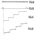
- FIGS 1A to 1D illustrate an example of a period's breakdown vertical synchronization signal VSYNC.
- the figures 1A and 1B respectively represent a signal CK clock and vertical synchronization signal VSYNC.
- Figure 1C illustrates the case where the period of signal VSYNC is divided into 4 equal parts.
- the period of the VSYNC signal is equivalent to 23 clock periods. Each part is therefore equivalent to 5 clock periods and the 3 periods clock juxtaposed to the last part.
- This technique therefore makes it possible to obtain a constant maximum amplitude whatever the period of the VSYNC signal since the period is split into one fixed number of parts, N, and that each part is associated with a given amplitude value.
- this cutting is not satisfactory because the last part to which is added the remaining part of the period, is disproportionate to the other parties.
- the solution is to distribute the remaining clock pulses across all parts of the VSYNC signal period.
- the number R is distributed in the N blocks of pulses of pulses remaining at the rate of one pulse at maximum per block.
- blocks are produced of almost equal pulses with B or B + 1 pulses clock.
- the accumulator includes a generator random numbers connected to a preload input of the accumulator register to charge in said register a different number for each period T of the input signal. Preloading at the start of each period T a different number in the register of the accumulator will avoid the effects of persistence on a television screen, i.e. avoid as much as possible only for two periods successive blocks of the same rank have B + 1 impulses.
- the cutting device further includes a binary digital counter additional to associate a specific number with each pulse block of period T corresponding to rank of this block in said period T, which counter additional receives on its counting input the end of block signals and outputs on an output of give the number associated with each pulse block.
- FIG. 2 shows a circuit making it possible to measure the period of the input signal VSYNC and to divide it by N in order to obtain the size of the N equal parts as well as that of the remaining part of the period.
- This circuit therefore performs the acquisition of the numbers B and R.
- This circuit includes a clock 1 delivering a large number A of pulses during a chosen period of the signal VSYNC. We can choose for example a clock 1 oscillating at 24 MHz. If the period of the signal VSYNC is 20 milliseconds (25 images per second), A is then equal to 480,000.
- the counter 2 receives on its counting input the clock signal CK coming from the clock 1 and, each time its strongest bit returns to zero, it causes the counting of a unit in the counter 3. If one look at the counting during a selected period of the signal VSYNC, it is noted that at the end of the counting, the counter 3 is loaded with a number equal to the number of times that the counter 2 has made turns.
- the counter 3 is then loaded with a number equal to the number of times that the counter 2 has counted up to 4096. If the period of the signal VSYNC is 20 milliseconds and if the clock frequency is 24 MHz, the counter 2 contains at the end of the count the value 768 corresponding to the number of pulses remaining R after division of A by N and the counter 3 contains the value 117 corresponding to the number B representing the quotient of the division of A by N. The counter 3 therefore stores at the end of the counting the number B of pulses contained in the blocks of pulses before distribution of the number R in these same blocks.
- the counters 2 and 3 are reset to zero each time a edge detector 6 detects a falling edge in the VSYNC synchronization signal.
- the state counters 2 and 3 is saved in registers, respectively 4 and 5, before resetting the counters.
- FIG. 3 shows a device for cutting out the period T of the signal VSYNC in N almost equal parts according to the invention.
- This system includes in particular the elements of figure 2 but these elements are at present organized differently. In practice, we are dealing with a microprocessor system. The reorganizing connections is therefore quite simple.
- Counter 3 now receives on its input count CK pulses from clock 1.
- This counter is actually a down counter which is preloaded before counting down with a sum value from a adder 8.
- This sum value corresponds to the size of a pulse block after distribution of the number R and can be equal to either B or B + 1.
- the adder 8 is responsible for adding the contents of register 5 with a value, 1 or 0, present at the output of an accumulator 7.
- the accumulator 7 receives as input the contents of the register 4.
- the means constituted of the adder 8 and of the accumulator 7 makes it possible to distribute, at the rate of one pulse per block, R pulses in R blocks randomly selected from the N VSYNC signal period pulse blocks.
- the structure of the accumulator 7 will be described in the figure 4.
- counter 3 Once counter 3 is preloaded, it count down, to the rhythm of the pulses of clock 1, its content until reaching the zero state. When this state is reached, it delivers on a passing output UNF (Underflow) an end of block pulse F. In other words, at each end of block, the counter 3 delivers an end signal of block F.
- This end signal of block F is applied on the one hand to a bet entry in service EN of the accumulator 7 so that the latter delivers on its OUT output a value 1 or 0, and other share on an ENP preload authorization entry from counter 3 to authorize the precharge of counter 3 with the sum value present at the output of the adder 8.
- This end of block signal is also applied on the count input CLK of counter 2 which is a M bit counter.
- Counter 2 then delivers for each block a number of M bits corresponding to the rank of this block in the period of the VSYNC signal. All binary numbers or words obtained at the output of the counter 2 then constitutes a binary tooth signal saw such as that shown in Figure 1D.
- This signal binary to be usable by the coils of deflection of a monitor or receiver television, is then transformed by a converter digital / analog 9 then applied to the coils of vertical deviation of the monitor.
- the accumulator 7 must be in able to deliver R values equal to 1 on a set of N values.
- Figure 4 describes a possible structure of the accumulator 7.
- the accumulator 7 comprises a data input IN, an activation input EN and a OUT output. It receives on the input IN the number R of pulses contained in register 4 and the EN input is connected to the UNF output of counter 3. It is consisting of an adder 10 with two inputs of data E1 and E2 on M bits, a data output S and an OVF holding output. Data output S is connected to the IN input of an M bit 11 register and the output OUT of register 11 is connected to the input E2 of the adder 10.
- the input E1 of the adder 11 is connected to the IN input of the accumulator 7 and its OVF output is connected to the OUT output of the accumulator. Finally, the EN activation input of the accumulator 7 is connected to the activation terminal EN from the register 11.
- the register 11 stores the value present at the output of the adder 10 at each once counter 3 sends an end of block F signal.
- S i the value obtained at the output of the adder 10.
- Each iteration i is triggered by an end of block signal F.
- the accumulator 7 includes a number generator 12. The output of this generator is connected at the preload input of register 11. This generator will allow to load a different number in the register 11 at each new signal period VSYNC synchronization and thus remove the effects of persistence on the screen that the fact could generate that, for two successive periods, two blocks of the same rank has B + 1 pulses.
- this random number generator 11 can be a generator delivering sequences of random numbers based on a polynomial with maximum sequence.
- the degree of this polynomial will be chosen according to the length of the desired sequence.
- the length of this sequence will preferably be equal to the number N of pulse blocks. A longer length sequence would be unnecessary.
- P (x) 1 + x 3 + x 10 .
- the implementation of such a polynomial is well known to those skilled in the art.
Landscapes
- Processing Of Color Television Signals (AREA)
- Picture Signal Circuits (AREA)
- Synchronizing For Television (AREA)
Abstract
Description
La présente invention a pour objet un dispositif de découpage de la période T d'un signal en N parties quasi-égales. Elle peut trouver son application dans tous les domaines, notamment dans le domaine de la télévision. Dans celui-ci, elle servira de préférence à produire un signal de balayage vertical à partir d'un signal de synchronisation verticale.The present invention relates to a device for dividing the period T of a signal into N parts almost equal. It can find its application in all areas, particularly in the area of television. In it, it will preferably be used to produce a vertical scan signal from a vertical synchronization signal.
L'invention sera décrite dans le contexte du traitement des signaux de télévision pour plus de facilité sans qu'on puisse y voir une quelconque limitation de la portée de l'invention. On connaít, dans les signaux de télévision pour visualiser des images sur des écrans cathodiques, les signaux de balayage vertical ainsi que les signaux de balayage horizontal. Ces signaux de balayage sont issus de signaux de synchronisation verticale et horizontale. Les signaux de balayage sont appliqués sur des bobines de déflexion d'un ou plusieurs canons projetant des électrons d'une cathode vers un écran électroluminescent. Pour constituer une image, on provoque ainsi le balayage de l'écran afin de constituer un certain nombre de lignes empilées les unes en dessous des autres de haut en bas.The invention will be described in the context of television signal processing for more than ease without being able to see any limitation of the scope of the invention. We know, in television signals to view images on CRT screens, signals from vertical scanning as well as the scanning signals horizontal. These scanning signals are derived from vertical and horizontal synchronization signals. Scanning signals are applied to coils of deflection of one or more guns projecting electrons from a cathode to a screen electroluminescent. To constitute an image, we thus causes the screen to be scanned in order to make up a number of rows stacked them one below the other from top to bottom.
Selon la résolution envisagée, ainsi que selon les normes de visualisation utilisées dans les différentes régions du monde, le nombre de lignes visualisées sur l'écran varie. Alors qu'on connaít actuellement des images avec 420 lignes ou 625 lignes, les nouvelles normes prévoient 1024 lignes ou même 2048. Par ailleurs la fréquence de rafraíchissement des images sur l'écran, 25 images par seconde, dépend également des standards et des qualités recherchés. On envisage notamment 100 images par seconde pour éviter les effets de scintillement. Des générateurs de signaux de balayage polyvalents sont donc réalisés pour faire face à ces différents standards.Depending on the proposed resolution, as well as visualization standards used in the different regions of the world, the number of lines viewed on the screen varies. While we currently know images with 420 lines or 625 lines, the news standards provide for 1024 lines or even 2048. Furthermore the refresh rate of the images on the screen, 25 frames per second, also depends on standards and qualities sought. We are considering including 100 frames per second to avoid the effects flicker. Signal generators versatile scans are therefore made to cope to these different standards.
Ces générateurs de signaux de balayage doivent générer, à partir de signaux de synchronisation, des signaux de balayage en dents de scie dont la période est égale à la période du signal de synchronisation correspondant et dont l'amplitude maximum est constante quelle que soit cette période. Il existe des signaux de synchronisation verticale et de synchronisation horizontale associés respectivement aux signaux de balayage vertical et horizontal. Ces signaux de synchronisation contiennent des informations de temps liées au début d'une ligne et au début d'une trame (ou d'une demi-trame). La période de ces signaux de synchronisation varie donc en fonction de la fréquence de rafraíchissement des images sur l'écran et en fonction du nombre de lignes visualisées sur l'écran.These sweep signal generators must generate, from synchronization signals, sawtooth sweep signals whose period is equal to the period of the synchronization signal corresponding and whose maximum amplitude is constant whatever this period. There are signals of vertical synchronization and synchronization horizontal associated respectively with the signals of vertical and horizontal scanning. These signals of synchronization contain time information linked to the start of a line and the start of a frame (or half a frame). The period of these signals of synchronization therefore varies depending on the frequency refresh images on screen and in depending on the number of lines displayed on the screen.
Jusqu'à présent, uniquement des circuits analogiques tel que le circuit moniteur TDA 9106 de SGS Thomson Microelectronics, réalisent cette fonction. Cependant, de tels circuits présentent une incertitude de l'ordre de 1% sur l'amplitude maximum des signaux de balayage à chaque changement de fréquence du signal de synchronisation. Ainsi, pour deux fréquences de balayage différentes, l'amplitude maximum des deux signaux de balayage peut être différente. La mise en oeuvre de tel circuit nécessite donc un réglage préalable du moniteur suivant la fréquence de rafraíchissement. A chaque changement de standard, par exemple de VGA à SVGA, il faut retoucher le bouton de position verticale de l'image.So far only circuits analogs such as SGS TDA 9106 monitor circuit Thomson Microelectronics, perform this function. However, such circuits present uncertainty of the order of 1% on the maximum amplitude of the signals sweep at each change of frequency of the signal synchronization. So for two frequencies of different scanning, the maximum amplitude of the two scanning signals may be different. Setting work of such a circuit therefore requires adjustment prior to the monitor according to the frequency of refreshment. At each change of standard, by example from VGA to SVGA, you have to touch up the vertical position of the image.
Aussi le principal problème que l'invention cherche à résoudre est de proposer un dispositif garantissant une amplitude maximum constante des signaux de balayage, quel que soit le standard employé.Also the main problem that the invention seeks to solve is to propose a device guaranteeing a constant maximum amplitude of scanning signals, whatever standard is used.
Pour pallier cet inconvénient, on prévoit l'utilisation d'un circuit numérique pour générer les signaux de balayage. La technique employée pour assurer une amplitude maximum constante consiste à découper la période du signal de synchronisation en N parties et d'associer une valeur d'amplitude à chaque partie pour former le signal de balayage. De cette façon, l'amplitude maximum du signal de balayage est fixée par le circuit numérique et ne dépend pas de la période du signal de synchronisation. Les figures 1A à 1D illustrent un exemple de découpage de la période d'un signal de synchronisation verticale VSYNC. Les figures 1A et 1B représentent respectivement un signal d'horloge CK et le signal de synchronisation verticale VSYNC. La figure 1C illustre le cas où la période du signal VSYNC est découpée en 4 parties égales. Dans cet exemple, la période du signal VSYNC est équivalente à 23 périodes d'horloge. Chaque partie est donc équivalente à 5 périodes d'horloge et les 3 périodes d'horloge restantes se juxtaposent à la dernière partie. Cette technique permet donc d'obtenir une amplitude maximum constante quelle que soit la période du signal VSYNC puisque la période est découpée en un nombre fixe de parties, N, et qu'à chaque partie est associée une valeur d'amplitude donnée. Cependant, ce découpage n'est pas satisfaisant car la dernière partie à laquelle se rajoute la partie restante de la période, est disproportionnée par rapport aux autres parties. Après conversion analogique de ce signal, on risque d'obtenir un signal analogique écrêté et cela veut dire que plusieurs lignes vidéo se superposeront sur l'écran. Aussi, la solution consiste à répartir les impulsions d'horloge restantes sur l'ensemble des parties de la période du signal VSYNC. Cette solution est décrite à la figure 1D. La période du signal de synchronisation VSYNC est alors découpée en N parties quasi-égales. Il faut noter qu'en pratique, la période d'un signal de synchronisation verticale sera découpée en un très grand nombre de parties, 4096 par exemple. Certaines de ces parties seront consacrées au retour trame mais ceci ne fait pas l'objet de la présente demande.To overcome this drawback, provision is made the use of a digital circuit to generate the scanning signals. The technique used to ensure a constant maximum amplitude consists in cutting the synchronization signal period in N parts and to associate an amplitude value to each part to form the scan signal. In this way, the maximum amplitude of the scanning signal is fixed by the digital circuit and does not depend on the period of the synchronization signal. Figures 1A to 1D illustrate an example of a period's breakdown vertical synchronization signal VSYNC. The figures 1A and 1B respectively represent a signal CK clock and vertical synchronization signal VSYNC. Figure 1C illustrates the case where the period of signal VSYNC is divided into 4 equal parts. In this example, the period of the VSYNC signal is equivalent to 23 clock periods. Each part is therefore equivalent to 5 clock periods and the 3 periods clock juxtaposed to the last part. This technique therefore makes it possible to obtain a constant maximum amplitude whatever the period of the VSYNC signal since the period is split into one fixed number of parts, N, and that each part is associated with a given amplitude value. However, this cutting is not satisfactory because the last part to which is added the remaining part of the period, is disproportionate to the other parties. After analog conversion of this signal, there is a risk get a clipped analog signal and that means that multiple video lines will overlap on the screen. Also, the solution is to distribute the remaining clock pulses across all parts of the VSYNC signal period. This solution is depicted in Figure 1D. The signal period of VSYNC synchronization is then split into N parts almost equal. It should be noted that in practice, the period of a vertical synchronization signal will be cut off in a very large number of parts, 4096 for example. Some of these parts will be devoted to the return frame but this is not the subject of this request.
Dans l'invention, on veut pouvoir découper la période d'un signal quelconque en N parties quasi-égales. Ce but est atteint dans l'invention en effectuant un comptage, pendant une période choisie du signal de synchronisation, des impulsions délivrées par une horloge suffisamment rapide pour produire beaucoup d'impulsions pendant cette période. On obtient, après ce comptage pendant une première période de durée, un nombre A d'impulsions lié à la fréquence de cette horloge et à la durée de cette période. On divise ensuite ce nombre d'impulsions par le nombre N pour obtenir un nombre B et un nombre R d'impulsions correspondant respectivement au quotient et au reste de la division de A par N. Ces étapes constituent la phase d'acquisition des nombres d'impulsions B et R. Ensuite, on répartit dans les N blocs d'impulsions le nombre R d'impulsions restantes à raison d'une impulsion au maximum par bloc. On précharge ensuite un compteur tantôt avec le nombre B, tantôt avec le nombre B+1 et on décompte des impulsions produites par l'horloge. A chaque fois qu'un bloc de B ou B+1 impulsions est compté, on délivre un signal de fin de bloc et on précharge à nouveau le compteur avec une nouvelle valeur.In the invention, we want to be able to cut out the period of any signal in N almost equal parts. This object is achieved in the invention by performing a count, for a selected period of synchronization signal, pulses delivered by a clock fast enough to produce a lot of pulses during this period. We get, after this counting for a first period of time, a number A of pulses linked to the frequency of this clock and the duration of this period. We divide then this number of pulses by the number N for get a number B and a number R of pulses corresponding respectively to the quotient and the rest of the division of A by N. These stages constitute the phase acquisition of the pulse numbers B and R. Then, the number R is distributed in the N blocks of pulses of pulses remaining at the rate of one pulse at maximum per block. We then preload a counter sometimes with the number B, sometimes with the number B + 1 and the pulses produced by the clock are counted. AT whenever a block of B or B + 1 pulses is counted, we issue an end of block signal and preload the counter again with a new one value.
L'invention a donc pour objet un dispositif de découpage de la période T d'un signal d'entrée en N blocs quasi-égaux en nombre d'impulsions d'horloge caractérisé en ce qu'il comporte :
- une horloge délivrant un nombre A d'impulsions pendant la période T du signal d'entrée, A étant inférieur ou égal à 2P+M, avec P et M entiers,
- un premier registre de M bits pour stocker un nombre R d'impulsions égal au reste de la division du nombre A d'impulsions par le nombre N, avec N égal à 2M,
- un second registre de P bits pour stocker un nombre B d'impulsions égal au quotient de la division du nombre A d'impulsions par le nombre N,
- un moyen de répartition pour inclure, à chaque période T, à raison d'une impulsion par bloc, R impulsions dans R blocs pris aléatoirement parmi lesdits N blocs d'impulsions de ladite période T,
- un compteur numérique binaire avec P bits dont l'entrée de précharge est connectée à la sortie dudit moyen de répartition délivrant lesdits blocs et dont l'entrée de comptage reçoit les impulsions d'horloge, lequel compteur produit un signal de fin de bloc,
- a clock delivering a number A of pulses during the period T of the input signal, A being less than or equal to 2 P + M , with P and M integers,
- a first register of M bits for storing a number R of pulses equal to the remainder of the division of the number A of pulses by the number N, with N equal to 2 M ,
- a second register of P bits for storing a number B of pulses equal to the quotient of the division of the number A of pulses by the number N,
- a distribution means for including, at each period T, on the basis of one pulse per block, R pulses in R blocks taken randomly from said N blocks of pulses of said period T,
- a binary digital counter with P bits whose precharge input is connected to the output of said distribution means delivering said blocks and whose counting input receives clock pulses, which counter produces an end of block signal,
Selon l'invention, on produit donc des blocs d'impulsions quasi-égaux comportant B ou B+1 impulsions d'horloge.According to the invention, therefore, blocks are produced of almost equal pulses with B or B + 1 pulses clock.
Dans un mode de réalisation préféré, l'accumulateur comporte :
- un additionneur recevant sur une première entrée le nombre R stocké dans le premier registre, sur une seconde entrée un nombre Si-1, et délivrant sur une première sortie le résultat Si de l'addition du nombre R avec le nombre Si-1, et sur une seconde sortie un nombre indiquant le dépassement de capacité de l'additionneur, laquelle seconde sortie est connectée à la sortie de l'accumulateur, et
- un registre comprenant une entrée de données connectée à la première sortie de l'additionneur, une entrée d'activation recevant le signal de fin de bloc dudit compteur, une entrée d'horloge recevant les impulsions de l'horloge et une sortie de données connectée à la seconde entrée de l'additionneur fournissant ledit nombre Si-1·
- an adder receiving on a first input the number R stored in the first register, on a second input a number S i-1 , and delivering on a first output the result S i of the addition of the number R with the number S i- 1 , and on a second output a number indicating the excess capacity of the adder, which second output is connected to the output of the accumulator, and
- a register comprising a data input connected to the first output of the adder, an activation input receiving the end of block signal from said counter, a clock input receiving the clock pulses and a connected data output at the second input of the adder providing said number S i-1 ·
Selon un perfectionnement du mode de réalisation du dispositif, l'accumulateur comporte un générateur de nombres aléatoires connecté à une entrée de précharge du registre de l'accumulateur pour charger dans ledit registre un nombre différent à chaque période T du signal d'entrée. Le fait de précharger au début de chaque période T un nombre différent dans le registre de l'accumulateur va permettre d'éviter des effets de persistance sur un écran de télévision, c'est-à-dire éviter autant que possible que pour deux périodes successives les blocs de même rang comporte B+1 impulsions.According to an improvement of the embodiment of the device, the accumulator includes a generator random numbers connected to a preload input of the accumulator register to charge in said register a different number for each period T of the input signal. Preloading at the start of each period T a different number in the register of the accumulator will avoid the effects of persistence on a television screen, i.e. avoid as much as possible only for two periods successive blocks of the same rank have B + 1 impulses.
En vue de son utilisation pour générer un signal de balayage en dent de scie, le dispositif de découpage comporte en outre un compteur numérique binaire supplémentaire pour associer un nombre propre à chaque bloc d'impulsions d'une période T correspondant au rang de ce bloc dans ladite période T, lequel compteur supplémentaire reçoit sur son entrée de comptage les signaux de fin de bloc et délivre sur une sortie de données le nombre associé à chaque bloc d'impulsions.For use in generating a signal saw blade, the cutting device further includes a binary digital counter additional to associate a specific number with each pulse block of period T corresponding to rank of this block in said period T, which counter additional receives on its counting input the end of block signals and outputs on an output of give the number associated with each pulse block.
D'autres caractéristiques et avantages de l'invention apparaítront à la lecture de la description détaillée qui suit et qui est faite en référence aux dessins annexés dans lesquels :
- les figure 1A à 1D, déjà décrites, représentent des diagrammes temporels illustrant le découpage de la période d'un signal de synchronisation verticale en quatre parties quasi-égales;
- la figure 2 est un circuit permettant l'acquisition des nombres B et R;
- la figure 3 est un générateur de signaux de balayage vertical comportant le dispositif de découpage de l'invention; et
- la figure 4 est le schéma d'un accumulateur selon l'invention;
- FIGS. 1A to 1D, already described, represent time diagrams illustrating the division of the period of a vertical synchronization signal into four almost equal parts;
- Figure 2 is a circuit for acquiring the numbers B and R;
- FIG. 3 is a generator of vertical scanning signals comprising the cutting device of the invention; and
- Figure 4 is the diagram of an accumulator according to the invention;
Pour découper le signal d'entrée, qui est ici le signal de synchronisation verticale VSYNC, en N parties quasi-égales, il faut tout d'abord mesurer la période de ce signal puis diviser cette période en N parties égales et répartir la partie restante de la période dans les N parties égales. Dans l'exemple d'application plus particulièrement décrit ici (génération d'un signal de balayage vertical), le nombre N de blocs est choisi de préférence supérieur au nombre de lignes que le moniteur de télévision est susceptible de montrer. Compte tenu du fait que, pour augmenter la résolution des images, ce nombre est en constante augmentation, on a donc choisi N = 4096. On choisit par ailleurs N égal à une puissance de 2 pour que la division par N s'effectue d'une manière très simple.To cut the input signal, which is here the vertical synchronization signal VSYNC, in N parts almost equal, we must first measure the period of this signal then divide this period into N parts equal and distribute the remaining part of the period in the N equal parts. In the application example more particularly described here (generation of a vertical scan signal), the number N of blocks is preferably chosen greater than the number of lines that the TV monitor is likely to show. Given the fact that to increase the resolution images, this number is constantly increasing, we therefore chose N = 4096. We also choose N equal at a power of 2 so that the division by N is done in a very simple way.
La figure 2 montre un circuit permettant de
mesurer la période du signal d'entrée VSYNC et de la
diviser par N afin d'obtenir la taille des N parties
égales ainsi que celle de la partie restante de la
période. Ce circuit effectue donc l'acquisition des
nombres B et R. Ce circuit comporte une horloge 1
délivrant un grand nombre A d'impulsions pendant une
période choisie du signal VSYNC. On pourra choisir par
exemple une horloge 1 oscillant à 24 MHz. Si la période
du signal VSYNC est de 20 millisecondes (25 images par
secondes), A est alors égal 480 000. Le circuit
comporte par ailleurs un premier compteur 2 de M bits
dont la sortie de retenue OVF est connectée à l'entrée
de comptage CLK d'un second compteur 3 de P bits. M est
défini par la relation N = 2M. Le compteur 2 reçoit sur
son entrée de comptage le signal d'horloge CK provenant
de l'horloge 1 et, chaque fois que son bit le plus fort
repasse à zéro, il provoque le comptage d'une unité
dans le compteur 3. Si on regarde le comptage pendant
une période choisie du signal VSYNC, on constate qu'à
l'issue du comptage, le compteur 3 est chargé avec un
nombre égal au nombre de fois que le compteur 2 a fait
de tours.FIG. 2 shows a circuit making it possible to measure the period of the input signal VSYNC and to divide it by N in order to obtain the size of the N equal parts as well as that of the remaining part of the period. This circuit therefore performs the acquisition of the numbers B and R. This circuit includes a
Dans l'exemple d'application qui nous intéresse,
le signal de synchronisation verticale VSYNC est
découpée en 4096 parties; le compteur 2 est donc un
compteur 12 bits (4096=212). A l'issue du comptage, le
compteur 3 est alors chargé avec un nombre égal au
nombre de fois que le compteur 2 a compté jusqu'à 4096.
Si la période du signal VSYNC est 20 millisecondes et
si la fréquence horloge est 24 MHz, le compteur 2
contient à l'issue du comptage la valeur 768
correspondant au nombre d'impulsions restantes R après
division de A par N et le compteur 3 contient la valeur
117 correspondant au nombre B représentant le quotient
de la division de A par N. Le compteur 3 emmagasine
donc à la fin du comptage le nombre B d'impulsions
contenues dans les blocs d'impulsions avant répartition
du nombre R dans ces mêmes blocs.In the example application that interests us, the vertical synchronization signal VSYNC is cut into 4096 parts;
Pour limiter le comptage à une seule période, les
compteurs 2 et 3 sont remis à zéro à chaque fois qu'un
détecteur de front 6 décèle un front descendant dans le
signal de synchronisation VSYNC. Par ailleurs, l'état
des compteurs 2 et 3 est sauvegardé dans des registres,
respectivement 4 et 5, avant la remise à zéro des
compteurs.To limit the count to a single period, the
La figure 3 montre un dispositif de découpage de la période T du signal VSYNC en N parties quasi-égales selon l'invention. Ce dispositif reprend notamment les éléments de la figure 2 mais ces éléments sont à présent organisés de manière différente. En pratique, on a affaire à un système à microprocesseur. La réorganisation des connexions est donc assez simple. FIG. 3 shows a device for cutting out the period T of the signal VSYNC in N almost equal parts according to the invention. This system includes in particular the elements of figure 2 but these elements are at present organized differently. In practice, we are dealing with a microprocessor system. The reorganizing connections is therefore quite simple.
Le compteur 3 reçoit à présent sur son entrée de
comptage les impulsions CK provenant de l'horloge 1. Ce
compteur est en fait un décompteur qui est préchargé
avant le décomptage par une valeur somme provenant d'un
additionneur 8. Cette valeur somme correspond à la
taille d'un bloc d'impulsions après répartition du
nombre R et peut être égal soit à B, soit à B+1. En
effet, l'additionneur 8 est chargé d'additionner le
contenu du registre 5 avec une valeur, 1 ou 0, présente
en sortie d'un accumulateur 7. L'accumulateur 7 reçoit
en entrée le contenu du registre 4. Le moyen constitué
de l'additionneur 8 et de l'accumulateur 7 permet de
répartir, à raison d'une impulsion par bloc, R
impulsions dans R blocs pris aléatoirement parmi les N
blocs d'impulsions de la période du signal VSYNC. La
structure de l'accumulateur 7 sera décrite à la figure
4.
Une fois que le compteur 3 est préchargé, il
décompte, au rythme des impulsions de l'horloge 1, son
contenu jusqu'à atteindre l'état zéro. Lorsque cet état
est atteint, il délivre sur une sortie de dépassement
UNF (Underflow) une impulsion de fin de bloc F.
Autrement dit, à chaque fin de bloc, le compteur 3
délivre un signal de fin de bloc F. Ce signal de fin de
bloc F est appliqué d'une part sur une entrée de mise
en service EN de l'accumulateur 7 pour que ce dernier
délivre sur sa sotie OUT une valeur 1 ou 0, et d'autre
part sur une entrée d'autorisation de précharge ENP du
compteur 3 pour autoriser la précharge du compteur 3
avec la valeur somme présente en sortie de
l'additionneur 8.Once
Ce signal de fin de bloc est également appliqué
sur l'entrée de comptage CLK du compteur 2 qui est un
compteur M bits. Le compteur 2 délivre alors pour
chaque bloc un nombre de M bits correspondant au rang
de ce bloc dans la période du signal VSYNC. L'ensemble
des nombres ou mots binaires obtenus à la sortie du
compteur 2 constitue alors un signal binaire en dent de
scie tel que celui représenté à la figure 1D. Ce signal
binaire, pour être exploitable par les bobines de
déflexion d'un moniteur ou d'un récepteur de
télévision, est ensuite transformé par un convertisseur
numérique/analogique 9 puis appliqué sur les bobines de
déviation verticale du moniteur.This end of block signal is also applied
on the count input CLK of
Dans ce dispositif, l'accumulateur 7 doit être en
mesure de délivrer R valeurs égales à 1 sur un ensemble
de N valeurs. La figure 4 décrit une structure possible
de l'accumulateur 7. L'accumulateur 7 comporte une
entrée de données IN, une entrée d'activation EN et une
sortie OUT. Il reçoit sur l'entrée IN le nombre R
d'impulsions contenu dans le registre 4 et l'entrée EN
est connectée à la sortie UNF du compteur 3. Il est
constitué d'un additionneur 10 comportant deux entrées
de données E1 et E2 sur M bits, une sortie de données S
et une sortie de retenue OVF. La sortie de données S
est connectée à l'entrée IN d'un registre M bits 11 et
la sortie OUT du registre 11 est connectée à l'entrée
E2 de l'additionneur 10. L'entrée E1 de l'additionneur
11 est connectée à l'entrée IN de l'accumulateur 7 et
sa sortie OVF est connectée à la sortie OUT de
l'accumulateur. Enfin, l'entrée d'activation EN de
l'accumulateur 7 est reliée à la borne d'activation EN
du registre 11.In this device, the
Ainsi connecté, le registre 11 emmagasine la
valeur présente en sortie de l'additionneur 10 à chaque
fois que le compteur 3 émet un signal de fin de bloc F. Thus connected, the
Pour expliquer le fonctionnement de l'accumulateur
7, on désigne par Si la valeur obtenue en sortie de
l'additionneur 10. Chaque itération i est déclenchée
par un signal de fin de bloc F. L'additionneur 10
effectue la fonction suivante:
En effet, par définition Si ∈ [0,N-1] et R ∈ [0,N-1].
Dans l'équation (2), Oi représente la retenue de
l'additionneur 10 à chaque itération.Indeed, by definition S i ∈ [0, N-1] and R ∈ [0, N-1]. In equation (2), O i represents the carry of the
Dans la suite, on va démontrer alors que :

De l'équation (2), en sommant les N équations
récurrentes, on peut en déduire que

Ce qui donne :

Par ailleurs, on connaít la propriété suivante :
Cette équation se simplifie en SN = S0 mod N = S0
De l'équation (3), on obtient alors

This equation is simplified in S N = S 0 mod N = S 0
From equation (3), we then obtain
Cette démonstration montre que sur un total de N
itérations, la retenue Oi sera R fois égale à 1. On
rajoute donc systématiquement la retenue Oi au nombre B
pour précharger le compteur 3. Ainsi, sur une période
du signal VSYNC, le compteur 3 sera préchargé R fois
par le nombre B+1 et N-R fois par le nombre B.This demonstration shows that on a total of N iterations, the reserve O i will be R times equal to 1. We therefore systematically add the reserve O i to the number B to preload the
Selon un mode de réalisation amélioré,
l'accumulateur 7 comporte un générateur de nombres
aléatoires 12. La sortie de ce générateur est connectée
à l'entrée de précharge du registre 11. Ce générateur
va permettre de charger un nombre différent dans le
registre 11 à chaque nouvelle période du signal de
synchronisation VSYNC et ainsi supprimer les effets de
persistance sur l'écran que pourrait engendrer le fait
que, pour deux périodes successives, deux blocs de même
rang comporte B+1 impulsions.According to an improved embodiment,
the
En pratique, ce générateur de nombres aléatoires
11 peut être un générateur délivrant des séquences de
nombres aléatoires basées sur un polynôme à séquence
maximale. Le degré de ce polynôme sera choisi en
fonction de la longueur de la séquence souhaitée. La
longueur de cette séquence sera de préférence égale au
nombre N de blocs d'impulsions. Une séquence de
longueur supérieure serait inutile. Par exemple, pour
obtenir une séquence de 1023 valeurs pseudo-aléatoires,
on utilisera le polynôme de degré 10 suivant :
P(x)=1+x3+x10. L'implémentation d'un tel polynôme est
bien connue de l'homme du métier.In practice, this
Claims (5)
Applications Claiming Priority (2)
| Application Number | Priority Date | Filing Date | Title |
|---|---|---|---|
| FR9615179A FR2757001B1 (en) | 1996-12-05 | 1996-12-05 | DEVICE FOR CUTTING THE PERIOD OF A SIGNAL INTO N NEARLY EQUAL PARTS |
| FR9615179 | 1996-12-05 |
Publications (1)
| Publication Number | Publication Date |
|---|---|
| EP0847141A1 true EP0847141A1 (en) | 1998-06-10 |
Family
ID=9498524
Family Applications (1)
| Application Number | Title | Priority Date | Filing Date |
|---|---|---|---|
| EP97460048A Ceased EP0847141A1 (en) | 1996-12-05 | 1997-11-27 | Apparatus for dividing a signal period into N quasi-equal shares |
Country Status (3)
| Country | Link |
|---|---|
| US (1) | US6072534A (en) |
| EP (1) | EP0847141A1 (en) |
| FR (1) | FR2757001B1 (en) |
Families Citing this family (4)
| Publication number | Priority date | Publication date | Assignee | Title |
|---|---|---|---|---|
| KR100240873B1 (en) * | 1997-08-26 | 2000-01-15 | 윤종용 | Serial interface unit having the same register for reception/transmission |
| US6392455B1 (en) * | 2001-03-30 | 2002-05-21 | Koninklijke Philips Electronics N.V. | Baud rate generator with fractional divider |
| US7342984B1 (en) * | 2003-04-03 | 2008-03-11 | Zilog, Inc. | Counting clock cycles over the duration of a first character and using a remainder value to determine when to sample a bit of a second character |
| US9264215B2 (en) * | 2013-10-25 | 2016-02-16 | Shenshen Sumoon Microeelectronida,Ltd. | Transmission protocol decoding method, device, and transmission protocol decoding chip |
Citations (3)
| Publication number | Priority date | Publication date | Assignee | Title |
|---|---|---|---|---|
| US4658406A (en) * | 1985-08-12 | 1987-04-14 | Andreas Pappas | Digital frequency divider or synthesizer and applications thereof |
| EP0280126A2 (en) * | 1987-02-21 | 1988-08-31 | Deutsche Thomson-Brandt GmbH | Programmable frequency divider for generating a low-frequency signal from a high-frequency signal |
| EP0322012A1 (en) * | 1987-12-07 | 1989-06-28 | Koninklijke Philips Electronics N.V. | Picture display device including a staircase generator |
Family Cites Families (14)
| Publication number | Priority date | Publication date | Assignee | Title |
|---|---|---|---|---|
| US4144579A (en) * | 1977-07-25 | 1979-03-13 | Rca Corporation | Arithmetic synthesizer frequency generation with reduced phase jitter |
| US4197509A (en) * | 1978-08-11 | 1980-04-08 | The United States Of America As Represented By The Secretary Of The Navy | Variable segmented ramp voltage synthesizer |
| US4974082A (en) * | 1985-09-21 | 1990-11-27 | Robert Bosch Gmbh | Digital pulse generator of phase and frequency periodically controlled precisely by external signals |
| JPH0683067B2 (en) * | 1987-10-13 | 1994-10-19 | 松下電器産業株式会社 | Frequency divider |
| DE3927967A1 (en) * | 1989-08-24 | 1991-02-28 | Bosch Gmbh Robert | ELECTRONIC COUNTER |
| DE69027390T2 (en) * | 1989-09-20 | 1996-11-14 | Canon Kk | Synchronization signal generator for an image signal reproduction device |
| US5052031A (en) * | 1990-08-14 | 1991-09-24 | At&T Bell Laboratories | Phase locked loop including non-integer multiple frequency reference signal |
| FR2666184A1 (en) * | 1990-08-24 | 1992-02-28 | Alcatel Radiotelephone | CLOCK WITH DIVISION OF FRACTIONAL FREQUENCY AND SERVING THIS CLOCK. |
| US5144255A (en) * | 1991-10-28 | 1992-09-01 | Allied-Signal Inc. | Multiple synchronized agile pulse generator |
| US5248900A (en) * | 1991-12-24 | 1993-09-28 | Intel Corporation | Time-sliced modular pulse-width modulation circuit |
| JP3241079B2 (en) * | 1992-02-24 | 2001-12-25 | 株式会社日立製作所 | Digital phase locked loop |
| US5416434A (en) * | 1993-03-05 | 1995-05-16 | Hewlett-Packard Corporation | Adaptive clock generation with pseudo random variation |
| KR100236088B1 (en) * | 1997-02-03 | 1999-12-15 | 김영환 | Clock divider |
| US5963106A (en) * | 1998-03-16 | 1999-10-05 | Sonic Innovations, Inc. | Double-sided pulse width modulator |
-
1996
- 1996-12-05 FR FR9615179A patent/FR2757001B1/en not_active Expired - Fee Related
-
1997
- 1997-11-27 EP EP97460048A patent/EP0847141A1/en not_active Ceased
- 1997-12-01 US US08/980,609 patent/US6072534A/en not_active Expired - Fee Related
Patent Citations (3)
| Publication number | Priority date | Publication date | Assignee | Title |
|---|---|---|---|---|
| US4658406A (en) * | 1985-08-12 | 1987-04-14 | Andreas Pappas | Digital frequency divider or synthesizer and applications thereof |
| EP0280126A2 (en) * | 1987-02-21 | 1988-08-31 | Deutsche Thomson-Brandt GmbH | Programmable frequency divider for generating a low-frequency signal from a high-frequency signal |
| EP0322012A1 (en) * | 1987-12-07 | 1989-06-28 | Koninklijke Philips Electronics N.V. | Picture display device including a staircase generator |
Non-Patent Citations (1)
| Title |
|---|
| "deflection drive system", IBM TECHNICAL DISCLOSURE BULLETIN, vol. 16, no. 6, November 1973 (1973-11-01), NEW YORK US, pages 1765, XP002036211 * |
Also Published As
| Publication number | Publication date |
|---|---|
| FR2757001B1 (en) | 1999-02-05 |
| FR2757001A1 (en) | 1998-06-12 |
| US6072534A (en) | 2000-06-06 |
Similar Documents
| Publication | Publication Date | Title |
|---|---|---|
| EP0128789B1 (en) | Method for realising a geometrical tranformation on a video picture, and device for carrying out this method | |
| WO1980001635A1 (en) | Information transmission system between a transmission center and receivers,this system being provided with a control means for access to the transmitted information | |
| EP0021938A1 (en) | Television system with access control using a variable electronic key | |
| EP0858066A1 (en) | Method and device for converting the digital image rate | |
| EP0142440A2 (en) | Generating device for a frequency being a fraction of a reference frequency | |
| EP0682828B1 (en) | Block interleaving and deinterleaving method and device therefor | |
| EP0029780B1 (en) | Equipment for testing a videography television receiver | |
| EP0071506A1 (en) | Digital method and device for the phase error correction of a sampled signal and its application to the correction of television signals | |
| EP0020999A1 (en) | Tester and method for measuring memory address access time using a data recirculating technique | |
| FR2522490A1 (en) | APPARATUS FOR ULTRASONIC DIAGNOSIS | |
| EP0847141A1 (en) | Apparatus for dividing a signal period into N quasi-equal shares | |
| FR2589302A1 (en) | INFRARED THERMOGRAPHY SYSTEM WITH IMPROVED SENSITIVITY BY PROGRESSIVE AMOUNTING OF IMAGE LINES | |
| EP0732845B1 (en) | Method and apparatus for synchronising a digital video signal | |
| EP0674302B1 (en) | Method of identification of video standard, and circuit realizing such method | |
| FR2740636A1 (en) | PROCESS ALLOWING THE CASCADE OF DETACHABLE CONDITIONAL ACCESS MODULES, CIRCUIT FOR INSERTING A PREDEFINED SEQUENCE AND DETECTION CIRCUIT OF THE SAID SEQUENCE FOR THE IMPLEMENTATION OF THE PROCEDURE | |
| CH625377A5 (en) | ||
| FR2577081A1 (en) | METHOD AND DEVICE FOR QUICK-PHASE SETTING A CLOCK SIGNAL | |
| FR2710799A1 (en) | Periodic signal generator. | |
| FR2707814A1 (en) | Device for measuring the duration of a time interval. | |
| EP0391784B1 (en) | Device and method for generating control signals | |
| EP0690623B1 (en) | Method of and device for inserting asynchronous data into a digital signal | |
| EP0126495A1 (en) | Descrambler for television pictures scrambled by circular permutation | |
| EP0289385A1 (en) | Reference time device with a constant stability for measuring long and short time intervals | |
| EP0140396B1 (en) | Process and device for reconstituting an analogous signal | |
| WO2003049442A1 (en) | Method for distributing scrambled digital data decryption keys |
Legal Events
| Date | Code | Title | Description |
|---|---|---|---|
| PUAI | Public reference made under article 153(3) epc to a published international application that has entered the european phase |
Free format text: ORIGINAL CODE: 0009012 |
|
| AK | Designated contracting states |
Kind code of ref document: A1 Designated state(s): DE FR GB IT |
|
| AX | Request for extension of the european patent |
Free format text: AL;LT;LV;MK;RO;SI |
|
| 17P | Request for examination filed |
Effective date: 19980611 |
|
| 17Q | First examination report despatched |
Effective date: 19980827 |
|
| RAP3 | Party data changed (applicant data changed or rights of an application transferred) |
Owner name: STMICROELECTRONICS S.A. |
|
| AKX | Designation fees paid |
Free format text: DE FR GB IT |
|
| RBV | Designated contracting states (corrected) |
Designated state(s): DE FR GB IT |
|
| STAA | Information on the status of an ep patent application or granted ep patent |
Free format text: STATUS: THE APPLICATION HAS BEEN REFUSED |
|
| 18R | Application refused |
Effective date: 19990307 |