EP0844415A1 - Cable drag chain - Google Patents
Cable drag chain Download PDFInfo
- Publication number
- EP0844415A1 EP0844415A1 EP97117229A EP97117229A EP0844415A1 EP 0844415 A1 EP0844415 A1 EP 0844415A1 EP 97117229 A EP97117229 A EP 97117229A EP 97117229 A EP97117229 A EP 97117229A EP 0844415 A1 EP0844415 A1 EP 0844415A1
- Authority
- EP
- European Patent Office
- Prior art keywords
- drag chain
- engaging pin
- cable drag
- side plate
- plate
- Prior art date
- Legal status (The legal status is an assumption and is not a legal conclusion. Google has not performed a legal analysis and makes no representation as to the accuracy of the status listed.)
- Granted
Links
Images


Classifications
-
- H—ELECTRICITY
- H02—GENERATION; CONVERSION OR DISTRIBUTION OF ELECTRIC POWER
- H02G—INSTALLATION OF ELECTRIC CABLES OR LINES, OR OF COMBINED OPTICAL AND ELECTRIC CABLES OR LINES
- H02G1/00—Methods or apparatus specially adapted for installing, maintaining, repairing or dismantling electric cables or lines
-
- F—MECHANICAL ENGINEERING; LIGHTING; HEATING; WEAPONS; BLASTING
- F16—ENGINEERING ELEMENTS AND UNITS; GENERAL MEASURES FOR PRODUCING AND MAINTAINING EFFECTIVE FUNCTIONING OF MACHINES OR INSTALLATIONS; THERMAL INSULATION IN GENERAL
- F16G—BELTS, CABLES, OR ROPES, PREDOMINANTLY USED FOR DRIVING PURPOSES; CHAINS; FITTINGS PREDOMINANTLY USED THEREFOR
- F16G13/00—Chains
- F16G13/12—Hauling- or hoisting-chains so called ornamental chains
- F16G13/16—Hauling- or hoisting-chains so called ornamental chains with arrangements for holding electric cables, hoses, or the like
Definitions
- the present invention relates to a cable drag chain for protecting and guiding safely and surely such flexible members as cable and hose which feed energy to a movable machine.
- a plurality of link members each comprising a pair of right and left side plates and connecting plates which connect upper and lower edges, respectively, of the side plates are connected contiguously in a bendable manner, and for receiving a cable, etc. in the interior of the link members, each connecting plate which connects the upper edges of the paired side plates transversely can be opened on both sides with respect to the paired right and left side plates.
- the present invention has solved the above-mentioned problems by a cable drag chain wherein a plurality of link members each comprising a pair of right and left side plates and connecting plates which connect transversely upper and lower edges, respectively, of the side plates are connected together contiguously in a bendable manner, a pair of elastically deformable connecting arms spaced from each other in the longitudinal direction of the cable drag chain are projected at each end of at least one connecting plate, a connecting arm receptacle portion for receiving the connecting arms therein is recessed in each side plate, engaging pins are projected from abutment surfaces of either the connecting arms or the connecting arm receptacle portion in the longitudinal direction of the cable drag chain, while engaging pin receptacle holes are formed in the abutment surfaces of the other of the connecting arms and the connecting arm receptacle portion, the engaging pin receptacle holes being closed in a connecting plate disconnecting direction.
- each connecting plate When the connecting arms of each connecting plate are pushed to the connecting arm receptacle portion of each side plate, the connecting arms, which are space apart from each other, are fitted into the receptacle portion while narrowing their spacing. Thereafter, the connecting arms expand, so that the engaging pins and the engaging pin receptacle holes come into concave-convex engagement with each other.
- the engaging pins be formed on the connecting arm-side abutment surfaces, while the engaging pin receptacle holes be formed in the receptacle portion-side abutment surfaces, and that engaging pin guide grooves which are inclined toward the receptacle portions be formed in the peripheral edge of each side plate.
- the engaging pins are positioned along the guide grooves, whereby the connecting arms are narrowed with respect to each other, and the connecting arms expand after guided into each receptacle portion, so that the engaging pins and the engaging pin receptacle holes are fitted together in concave-convex engagement.
- the engaging pins are formed on the receptacle portion-side abutment surface, while the engaging pin receptacle holes are formed in the connecting arm-side abutment surfaces, and an engaging pin guide groove inclined in a converging direction is formed in the lower surface of each connecting arm.
- the connecting arms are narrowed with respect to each other and expand after guided into each receptacle portion, so that the engaging pins and the engaging pin receptacle holes are fitted together in concave-convex engagement.
- engaging pin fitting grooves communicating with the engaging pin receptacle holes formed in each side plate, the engaging pin fitting grooves being open sideways of the side plate, and connecting arm disengagement preventing stoppers are projected from the bottom of the receptacle portion of the side plate, the stoppers being adapted to engage the connecting arms with engaging pins fitted in the engaging pin receptacle holes in concave-convex engagement.
- the connecting plate is moved pivotally about the one end portion of the connecting plate and the other end of the connecting plate is mounted to the side plate.
- the connecting arm disengagement preventing stoppers projected on the bottom of the receptacle portion of the side plate come into engagement with the connecting arms so that the connecting arms may not become disengaged easily from the side plate. Therefore, in connecting the other end of the connecting plate to the side plate after connecting one end thereof to the side plate, the connecting plate moves pivotally about the engaging pins without being disengaged from the side plate. Also when disengaging the other end of the connecting plate from the side plate and allowing it to swing about one end thereof, the connecting plate swings about the engaging pins without disengagement from the side plate.
- a connecting plate disconnecting tool insertion port which opens sideways of the side plate, is formed in the connecting arm receptacle portion of the side plate, and a connecting plate disconnecting tool insertion port, which opens above the connecting arms, is formed by projecting the opposed surfaces of the connecting arms in a face-to-face relation to each other in the connecting plate.
- a connecting plate disconnecting tool insertion port which opens sides of the side plate, is formed in the connecting arm receptacle portion of the side plate, and the lower surface of each connecting arm opposed to the bottom of the connecting plate disconnecting tool insertion port is formed with a tool retaining surface which converges toward the bottom.
- the connecting arms are twisted in directions opposite to each other. Since the tool retaining surfaces formed on the undersides of the connecting arms converge toward the bottom, even if the connecting arms are twisted with respect to each other, a releasing force from the tool acts upward on the connecting arms.
- the connecting plates and the side plates are abutted each other at respective inward fall correcting surfaces on a central side in the transverse direction of the cable drag chain relative to the concave-convex fitting positions of the side plates and the connecting plates.
- the connecting plates and the side plates start mutual abutment at the respective inward fall correcting surfaces, so that even when the side plates fall inwards, their postures are corrected.
- the engaging pins can be smoothly fitted in the engaging pin receptacle holes.
- inward fall correcting portions are erected on the bottom of each connecting arm receptacle portion recessed in each side plate, opposed surfaces of the inward fall correcting portions are used as inward fall correcting surfaces, and each connecting plate and each side plate are abutted together at the inward fall correcting surfaces.
- inward fall correcting portions are erected on the bottom of each connecting arm receptacle portion recessed in each side plate, opposed surfaces of the inward fall correcting portions are used as inward fall correcting surfaces, and each connecting plate and each side plate are abutted together at the inward fall correcting surfaces.
- a slit is formed between the inward fall correcting portions to space the inward fall correcting portions away from each other in the longitudinal direction of the cable drag chain, and a projection for snap engagement with the slit is formed on each end of the connecting plate.
- the connecting arms are guided accurately to the engaged positions of the engaging pins and the engage pin receptacle holes, thus facilitating the engagement between the connecting arms and the side plates.
- a cable drag chain 10 as shown its whole in a front view of Fig. 1, comprises a plurality of resinous link members 12 connected together in a bendable manner.
- the cable drag chain 10 is for receiving therein and protecting cable and hose extending from a floor surface F to a motor M for example.
- each link member 12 has a pair of right and left side plates 14, 16 and connecting plates 18, 20 which connect transversely upper and lower edges, respectively, of the side plates.
- the connecting plate 18 which connects transversely the upper edges of the side plates 14 and 16 can be connected disconnectably to the side plates. In a connected state to the side plate 14 or 16, the connecting plate 18 is movable pivotally with respect to the side plate.
- the connecting plate 20 which connects transversely the lower edges of the side plates 14 and 16 is formed integrally with the side plates.
- the lower edge connecting plate 20 can also be made disconnectable from the side plates 14 and 16.
- the side plates 14, 16 and the connecting plate 18 are connected together by concave-convex engagement of the engaging pins and the engaging pin receptacle holes. Disconnection of the connecting plate 18 is performed sideways of or from above the cable drag chain 10 with use of a connecting plate disconnecting tool T such as a driver for example, as shown in Fig. 3.
- a connecting plate disconnecting tool T such as a driver for example
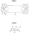
- FIGs. 4 and 5 illustrate the connecting plate 18.
- a pair of connecting arms 22, 22 are projected from both ends of the connecting plate 18.
- a connecting arm receptacle portion 24 for receiving the connecting arms 22, 22 therein is recessed in the upper edge of the side plate centrally in the longitudinal direction of the cable drag chain.
- the connecting arms 22, 22 are in abutment with the receptacle portion 24 longitudinally of the cable drag chain.
- Engaging pins 26 are projected from the abutment surfaces of the connecting arms 22, 22, while engaging pin receptacle holes 28 are formed in the abutment surfaces of the receptacle portion 24.
- the pin receptacle holes 28 are open sideways of the side plates 14 and 16, but are closed at the upper edges of the side plates 14 and 16, thus making it difficult for the connecting plate 18 to be disconnected above the side plates 14 and 16.
- the side openings of the side plates 14 and 16 are slightly narrower than the diameter of each engaging pin 26 so that the engaging pin 26 does not easily come off the engaging pin receptacle hole 28 after concave-convex engagement of the two. According to this construction, when the engaging pin 22 is engaged with the engaging pin receptacle hole 24 at one end of the connecting plate 18, the connecting plate 18 is pivotable with respect to one side plate.
- engaging pin guide grooves 30 which are inclined toward the receptacle portion 24.
- the connecting plate 18 After the engaging pins 26 of the connecting arms 22 are inserted from the side openings of the side plate 14 (16) into the engaging pin receptacle holes 28, or after the engaging pins 26 are inserted along the engaging pin guide grooves 30 formed in the side plate 14 (16), if the other end of the connecting plate 18 is pushed in from the upper edge of the other side plate, the connecting arms 22 get into the receptacle portion 24 while undergoing elastic deformation and narrowing the spacing of the two.
- the connecting arms 22, 22 expand and now the connection of the connecting plate 18 with the side plates 14 and 16 is completed.
- the side plates 14, 16 and the connecting plate 18 are transversely in abutment with each other at respective inward fall correcting surfaces on a central side relative to the concave-concave fitting positions of the engaging pins 26 and the engaging pin receptacle holes 28.
- Inward fall correcting surfaces of the connecting plate 18 are formed at a pair of shoulder portions 34, 34 located outside the connecting arms 22 and also at a front end of a projecting portion 36 formed between the connecting arms 22.
- inward fall correcting surfaces of the side plates 14 and 16 are formed at front ends of a pair of connecting arm holding arms 38, 38 projected in a face-to-face relation to each other and are also formed at projecting portions 40 projecting upward from the respective receptacle portions 24.
- the inward fall correcting surfaces of the shoulder portions 34, 34 and the projecting portion 36 form a shape which permits their contact with the connecting arm holding arms 38, 38 and the projecting portion 40 and permits rotation about the engaging pins 26. Only the shoulder portions 34, 34 and the connecting arm holding arms 38, 38 may be abutted with each other, or only the projecting portions 36 and 40 may be abutted with each other.
- the inward fall correcting surfaces of the side plates 14, 16 and those of the connecting plate 18 come into abutment with each other, whereby even if the side plates 14 and 16 fall inwards, their postures can be corrected.
- the connecting arms 22 are fitted in the receptacle portion 24, first the inward fall correcting surfaces come into abutment with each other and thereafter the engaging pins 26 are fitted in the engaging pin receptacle holes 28 along the engaging pin guide grooves 30.
- the positioning of the engaging pins 26 and the engaging pin receptacle holes 28 is conducted in advance, even in the case of connecting plural connecting plates 18 to the side plates 14 and 16, the connection can be done quickly.
- the connecting plate 18 can be disconnected sideways of and from above the link member 12.
- a tool insertion port 42 which opens sideways of the side plate.
- the connecting arms 22 are projected in a face-to-face relation to each other, and cut-in portions 44 are formed on the back side, to define a tool insertion port 46 which opens above the connecting arms 22.
- a tool is inserted into the tool insertion port 42 which opens sideways, whereby the connecting arms 22 undergo an elastic deformation and the engaging pins 26 get out of the engaging pin receptacle holes 28, so that the connecting plate 18 is disengaged at one end thereof from the side plate.
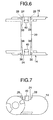
- engaging pins 26 are formed on the connecting arms 22 and the engaging pin receptacle holes 28 are formed in the receptacle portion 24
- engaging pins 52 are formed on abutment surfaces of a receptacle portion 50
- engaging pin receptacle holes 56 are formed in abutment surfaces of connecting arms 54
- engaging pin guide grooves 58 each inclined toward a converging direction are formed in the lower surfaces of the connecting arms.
- the connecting arms 54, 54 are press-fitted into the receptacle portion 50 while narrowing their spacing.
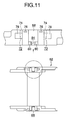
- Figs. 9 to 14 illustrate a cable drag chain according to another embodiment of the present invention, of which Figs. 9 and 10 illustrate a connecting plate, Figs. 11 and 12 illustrate a side plate, and Figs. 13 and 14 illustrate a connected state of the connecting plate to the side plate.
- the cable drag chain comprises link members connected together contiguously in a bendable manner, the link members each having a pair of right and left side plates 62, 62 and a connecting plate 64 which connects the upper edges of the side plates 62, 62 transversely. The lower edges of the side plates 62, 62 are connected with each other through another connecting plate (not shown).
- a pair of connecting arms 66, 66 are projected at each end of the connecting plate 64.
- a connecting arm receptacle portion 68 for receiving the connecting arms 66 therein is recessed in the upper edge of each side plate 62 centrally in the longitudinal direction of the cable drag chain.
- the connecting arms 66, 66 are abutted with the receptacle portion 68 longitudinally of the cable drag chain.
- Engaging pins 70 are projected from the abutment surfaces of the connecting arms 66, while engaging pin receptacle holes 72 are formed in the abutment surfaces of the receptacle portion 68.
- the engaging pin receptacle holes 72 are open sideways of the side plate 62 through engaging pin fitting grooves 74. However, the holes 72 close the upper edge of the side plate 62. Thus, once the engaging pins 70 are guided into the engaging pin receptacle holes 72 through the engaging pin fitting grooves 74, the connecting plate 64 is difficult to be disconnected above the side plates 62, 62.
- Connecting arm disengagement preventing stoppers 76 are projected from the bottom of the connecting arm receptacle portion 68 at more sideways positions of each side plate than the engaging pin receptacle holes 72.
- Connecting arm disengagement preventing stoppers 76 are projected from the bottom of the connecting arm receptacle portion 68 at more sideways positions of each side plate than the engaging pin receptacle holes 72.
- Engaging pin guide grooves 78 inclined toward the receptacle portion 68 are formed in the upper edge of each side plate 62 and above the engaging pin receptacle holes 72.
- inward fall correcting portions 80 projected upward from the bottom of the receptacle portion 68 of each side plate 62, and between the connecting arms 66, 66 of the connecting plate 64 is projected an inward fall correcting portion 82 which comes into abutment with the inward fall correcting portions 80.
- the inward fall correcting portions 80 are formed in the wall thickness of the receptacle portion 68 and are not projecting into the inner support space of the cable drag chain.
- the paired inward fall correcting portions 80 of each side plate are spaced apart in the longitudinal direction of the cable drag chain and a slit 84 is formed therebetween.
- the inward fall correcting portion 80 is formed equal to the spacing between the paired connecting arms 66, 66 of the connecting plate 64.
- the inward fall correcting portion 82 of the connecting plate 64 is formed equal to the spacing between the inward fall correcting portions 80, 80 of each side plate 62, and the front end of each inward fall correcting portion 82 of the connecting plate 64 is inclined toward the inner support space of the cable drag chain.
- the inward fall correcting portions 82, 82 of the connecting plate 64 are centrally provided with a positioning lug 86 for concave-convex engagement with the slit 84.
- the positioning lug 86 is inclined so that both faces converge at the lower end of the lug.
- the connecting plate 64 connected at one end thereof to one side plate 62 is connected to the other side plate 62, the lug 86 of the inward fall correcting portion 82 shorter than the connecting arms 66 gets into the slit 84 and the paired connecting arms 66, 66 sandwich the inward fall correcting portions 80 of the side plate 62 therebetween, whereby the side plate 62 and the connecting plate 64 are positioned in the longitudinal direction of the cable drag chain.
- the inward fall correcting portion 82 of the connecting plate comes into abutment with the inward fall correcting portions 80 of the side plate, whereby the side plate 62 and the connecting plate 64 are positioned also in the transverse direction of the cable drag chain.
- the inward fall is corrected by connecting the connecting plate 64 to the side plates 62, 62. Since the connecting plate 64 is connected by concave-convex engagement with each side plate 62, the prevention of its dislodgment is enhanced.
- connecting plate disconnecting tool insertion ports are formed above and sideways of the cable drag chain so that the connecting plate can be removed in two directions.
- tool retaining surfaces 90, 90 are formed on the front end undersides of the connecting arms 66, 66 of the connecting plate 64.
- the tool retaining surfaces 90, 90 converge toward the bottom of a sideways, connecting plate disconnecting tool insertion port 88.
- the tool retaining surfaces 90, 90 are substantially parallel to the bottom and the disconnecting force of the tool acts upward.
- the connecting plates of many link members it is necessary to remove the connecting plates of many link members. But the tool retaining surfaces on the front end undersides of the connecting arms permit the connecting plate disconnecting work to be done efficiently.
- elastically deformable connecting arms are projected at both ends of a connecting plate, while a connecting arm receptacle portion is recessed in each side plate, and engaging pins and engaging pin receptacle holes are formed on abutment surfaces in the longitudinal direction of the cable drag chain, the engaging pin receptacle boles being closed in the connecting plate disconnecting direction. Therefore, even when a force acting to disconnect the connecting plate from each side plate is exerted on the connecting plate, it is possible to keep the connecting plate connected to the side plate and surely protect cable and hose because the disconnecting direction of the connecting plate from the side plate and the disengaging direction of the engaging pins from the engaging pin receptacle holes are different.
- engaging pins are formed on abutment surfaces of the connecting arms, engaging pin receptacle holes are formed in abutment surfaces of the connecting arm receptacle portion, and engaging pin guide grooves inclined toward the receptacle portion are formed in the peripheral edge of the side plate. Therefore, when the connecting arms with the engaging pins are press-fitted into the connecting arm receptacle portion, the engaging pins are guided by the engaging pin guide grooves and the connecting arms are deformed while narrowing their spacing and are smoothly fitted into the receptacle portion.
- plural connecting plates can be connected successively to the side plates.
- the engaging pins are formed on the connecting arms of the connecting plate, even if the mounting and removal of the connecting plate to and from the side plates are repeated, resulting in wear of the engaging pins, the maintenance of the cable drag chain can be effected by only replacing the connecting plate with new one. This is advantageous in point of both the number of working steps and economy in comparison with the case where the whole of the link member must be replaced with new one.
- engaging pins are formed on the receptacle portion-side abutment surfaces, while engaging pin receptacle holes are formed in the connecting arm-side abutment surfaces, and an engaging pin guide groove inclined toward a converging direction is formed in the underside of each connecting arm. Therefore, as is the case with the invention of claim 2, when the connecting arms are press-fitted into the connecting arm receptacle portion, the connecting arms are deformed while narrowing their spacing and are smoothly fitted into the receptacle portion, thus permitting plural connecting plates to be connected successively to each side plate.
- connecting arm disengagement preventing stopper projected from the bottom of the receptacle portion comes into engagement with the connecting arms, so that the connecting plate connected at one end thereof to the side plate swings in the fitted state of the engaging pins into the engaging pin receptacle holes and is not disconnected easily from the side plate.
- the connecting plate connected at one end thereof to one side plate and about to be connected at the other end thereof to the other side plate, or the connecting plate disconnected only at the other end thereof from the other side plate can swing while being held at one end thereof by the one side plate. Therefore, not only the mounting of the connecting plate can be done smoothly but also the inspection of support members located inside the cable drag chain can be done easily by removing the connecting plate at the other end thereof.
- a connecting plate disconnecting tool insertion port which opens sideways of each side plate is formed in the connecting arm receptacle portion, but also a connecting plate disconnecting tool insertion port is formed so as to open above the connecting arms. Therefore, when the engaging pins and the engaging pin receptacle holes are fitted together in concave-convex engagement and the connecting plate is to be removed in this state, the tool can be inserted sideways of or above the cable drag chain. Thus, at the time of maintenance or replacement of cable or hose, even if a rail wall or any other member is located around the cable drag chain, the worker can remove the connecting plate in a direction convenient to the work. In this way the maintenance work can be done in an extremely efficient manner irrespective of how the cable drag chain is installed.
- a connecting plate disconnecting tool insertion port which opens sideways of each side plate is formed in the connecting plate receptacle portion, and a tool retaining surface is formed on the underside of each connecting arm opposed to the bottom of the connecting plate disconnecting tool insertion port, the tool retaining surface converging toward the bottom. Therefore, it becomes easy to disengage the connecting arms. More specifically, when the tool is inserted into the connecting plate disconnecting insertion port and an attempt is made to disengage the connecting arms from the side plate, the connecting arms are twisted in directions opposite to each other, but the tool retaining surfaces converging toward the bottom of the connecting plate disconnecting tool insertion port cause an upward force of the tool to act efficiently on the connecting arms. Consequently, the work for disengaging the engaging pins of the connecting arms from the engaging pin receptacle holes formed in the side plate becomes easier and hence it is easy to disassemble the cable drag chain and effect maintenance of internal support members.
- both plates come into abutment with each other at their abutment surfaces prior to concave-convex engagement of the engaging pins and the engaging pin receptacle holes, whereby positioning is effected for the concave-convex engagement of the engaging pins and the engaging pin receptacle holes. Therefore, even in the event side plates undergo an inward fall deformation, a plurality of connecting plates can be connected to the side plates quickly.
- inward fall correcting portions having inward fall correcting surfaces are formed on the bottom of the connecting arm receptacle portion of each side plate and the inward fall correcting portions can be formed within the wall thickness of the side plate, so it is possible to eliminate protrusions in the interior of the cable drag chain formed between the opposed faces of the side plates and thereby ensure protection and safety of the worker and prevent damage of support members located inside the chain.
Landscapes
- Engineering & Computer Science (AREA)
- General Engineering & Computer Science (AREA)
- Mechanical Engineering (AREA)
- Electric Cable Arrangement Between Relatively Moving Parts (AREA)
- Guides For Winding Or Rewinding, Or Guides For Filamentary Materials (AREA)
Abstract

Description
Claims (10)
Applications Claiming Priority (6)
| Application Number | Priority Date | Filing Date | Title |
|---|---|---|---|
| JP273488/96 | 1996-10-16 | ||
| JP27348896 | 1996-10-16 | ||
| JP27348896 | 1996-10-16 | ||
| JP216525/97 | 1997-08-11 | ||
| JP21652597 | 1997-08-11 | ||
| JP21652597A JP3356659B2 (en) | 1996-10-16 | 1997-08-11 | Cable drag chain |
Publications (3)
| Publication Number | Publication Date |
|---|---|
| EP0844415A1 true EP0844415A1 (en) | 1998-05-27 |
| EP0844415B1 EP0844415B1 (en) | 2002-09-11 |
| EP0844415B2 EP0844415B2 (en) | 2010-09-08 |
Family
ID=26521485
Family Applications (1)
| Application Number | Title | Priority Date | Filing Date |
|---|---|---|---|
| EP97117229A Expired - Lifetime EP0844415B2 (en) | 1996-10-16 | 1997-10-06 | Cable drag chain |
Country Status (5)
| Country | Link |
|---|---|
| US (1) | US5881548A (en) |
| EP (1) | EP0844415B2 (en) |
| JP (1) | JP3356659B2 (en) |
| KR (1) | KR100270208B1 (en) |
| DE (1) | DE69715352T3 (en) |
Cited By (5)
| Publication number | Priority date | Publication date | Assignee | Title |
|---|---|---|---|---|
| WO2000063586A1 (en) * | 1999-04-19 | 2000-10-26 | Igus Spritzgussteile für die Industrie GmbH | Cable carrier chain |
| EP1705401A3 (en) * | 2005-03-21 | 2007-01-17 | Murrplastik Systemtechnik GmbH | Chain link for a supporting chain for energy carriers |
| WO2007076987A1 (en) * | 2005-12-23 | 2007-07-12 | Kabelschlepp Gmbh | Chain link with a locking device |
| US8196384B2 (en) | 2005-12-23 | 2012-06-12 | Tsubaki Kabelschlepp GmbH | Chain link having a multi-axis link joint |
| CN106133393A (en) * | 2014-04-04 | 2016-11-16 | 株式会社椿本链条 | The guiding device of bar |
Families Citing this family (14)
| Publication number | Priority date | Publication date | Assignee | Title |
|---|---|---|---|---|
| DE19645403A1 (en) * | 1996-11-04 | 1998-05-07 | Kabelschlepp Gmbh | Chain link and energy chain with lockable crossbar |
| JP3157491B2 (en) * | 1997-11-28 | 2001-04-16 | 株式会社椿本チエイン | Flexible guide support chain |
| DE10118328A1 (en) * | 2001-04-12 | 2002-11-21 | Kabelschlepp Gmbh | Method for producing a chain link and chain link of an energy chain |
| DE10216043A1 (en) * | 2002-04-11 | 2003-10-23 | Kabelschlepp Gmbh | Line routing unit for the active routing of lines, cables or the like |
| JP3616625B2 (en) * | 2002-10-03 | 2005-02-02 | 株式会社椿本チエイン | Conveyor chain |
| JP3722482B2 (en) * | 2003-02-17 | 2005-11-30 | 株式会社椿本チエイン | Cable protection guide device |
| JP4144869B2 (en) * | 2003-09-11 | 2008-09-03 | 株式会社椿本チエイン | Cable protection guide device |
| DE202009005737U1 (en) * | 2009-04-17 | 2010-01-07 | Igus Gmbh | Crosspiece for a link in a cable routing device |
| DE202013101462U1 (en) * | 2013-04-05 | 2013-04-19 | Igus Gmbh | Power supply chain |
| US20150107209A1 (en) * | 2013-10-22 | 2015-04-23 | Deere & Company | Height Sensor for Harvesting Head |
| JP6060064B2 (en) * | 2013-11-11 | 2017-01-11 | 株式会社椿本チエイン | Cable protection guide device |
| KR101689655B1 (en) | 2014-12-09 | 2016-12-27 | 현대중공업 주식회사 | Cargo loading ship including wiring guide |
| KR101705000B1 (en) | 2014-12-22 | 2017-02-09 | 현대중공업 주식회사 | Wiring movement support apparatus |
| CN112962198A (en) * | 2021-02-05 | 2021-06-15 | 宿州雅辰百货有限公司 | Spinning wire equipment capable of automatically adjusting height of baffle according to rotating speed |
Citations (4)
| Publication number | Priority date | Publication date | Assignee | Title |
|---|---|---|---|---|
| DE3709740A1 (en) * | 1987-03-25 | 1988-10-06 | Ernst Klein | Self-supporting power-supply chain which can be bent on one side |
| JPH0352774U (en) | 1989-09-28 | 1991-05-22 | ||
| JPH0352774Y2 (en) * | 1988-04-14 | 1991-11-15 | ||
| DE4313075A1 (en) | 1993-04-21 | 1994-11-03 | Igus Gmbh | Energy-carrying chain |
Family Cites Families (7)
| Publication number | Priority date | Publication date | Assignee | Title |
|---|---|---|---|---|
| DE3522885A1 (en) * | 1985-06-26 | 1987-01-08 | Gebr Hennig Gmbh | Energy supply chain |
| US4833876A (en) * | 1987-04-09 | 1989-05-30 | Tsubakimoto Chain Co. | Carrier for cables and the like |
| JPH069743B2 (en) * | 1989-07-19 | 1994-02-09 | 新日本製鐵株式会社 | Groove detection method and device |
| DE3929095A1 (en) * | 1989-09-01 | 1991-03-21 | Igus Gmbh | Conveyor belt with demountable plates - has clip fastening between sides of belt and hinge construction plates |
| DE4105651A1 (en) * | 1991-02-22 | 1992-09-03 | Kabelschlepp Gmbh | POWER SUPPLY CHAIN |
| US5108350A (en) * | 1991-03-06 | 1992-04-28 | A&A Manufacturing Co., Inc. | Conduit carrier chain |
| DE4121433C1 (en) * | 1991-06-28 | 1993-02-04 | Ekd Gelenkrohr Gmbh, 4006 Erkrath, De |
-
1997
- 1997-08-11 JP JP21652597A patent/JP3356659B2/en not_active Expired - Lifetime
- 1997-10-06 DE DE69715352T patent/DE69715352T3/en not_active Expired - Lifetime
- 1997-10-06 EP EP97117229A patent/EP0844415B2/en not_active Expired - Lifetime
- 1997-10-13 US US08/949,231 patent/US5881548A/en not_active Expired - Lifetime
- 1997-10-16 KR KR1019970052996A patent/KR100270208B1/en not_active IP Right Cessation
Patent Citations (4)
| Publication number | Priority date | Publication date | Assignee | Title |
|---|---|---|---|---|
| DE3709740A1 (en) * | 1987-03-25 | 1988-10-06 | Ernst Klein | Self-supporting power-supply chain which can be bent on one side |
| JPH0352774Y2 (en) * | 1988-04-14 | 1991-11-15 | ||
| JPH0352774U (en) | 1989-09-28 | 1991-05-22 | ||
| DE4313075A1 (en) | 1993-04-21 | 1994-11-03 | Igus Gmbh | Energy-carrying chain |
Cited By (8)
| Publication number | Priority date | Publication date | Assignee | Title |
|---|---|---|---|---|
| WO2000063586A1 (en) * | 1999-04-19 | 2000-10-26 | Igus Spritzgussteile für die Industrie GmbH | Cable carrier chain |
| US6550233B2 (en) | 1999-04-19 | 2003-04-22 | Igus Spritzgussteile für die Industrie GmbH | Energy guiding chain |
| EP1705401A3 (en) * | 2005-03-21 | 2007-01-17 | Murrplastik Systemtechnik GmbH | Chain link for a supporting chain for energy carriers |
| WO2007076987A1 (en) * | 2005-12-23 | 2007-07-12 | Kabelschlepp Gmbh | Chain link with a locking device |
| US8196384B2 (en) | 2005-12-23 | 2012-06-12 | Tsubaki Kabelschlepp GmbH | Chain link having a multi-axis link joint |
| CN106133393A (en) * | 2014-04-04 | 2016-11-16 | 株式会社椿本链条 | The guiding device of bar |
| US9765852B2 (en) | 2014-04-04 | 2017-09-19 | Tsubakimoto Chain Co. | Device for guiding long object |
| CN106133393B (en) * | 2014-04-04 | 2018-03-20 | 株式会社椿本链条 | The guiding device of bar |
Also Published As
| Publication number | Publication date |
|---|---|
| DE69715352T3 (en) | 2010-12-30 |
| DE69715352D1 (en) | 2002-10-17 |
| JPH10176738A (en) | 1998-06-30 |
| JP3356659B2 (en) | 2002-12-16 |
| KR19980032876A (en) | 1998-07-25 |
| EP0844415B2 (en) | 2010-09-08 |
| EP0844415B1 (en) | 2002-09-11 |
| DE69715352T2 (en) | 2003-01-02 |
| US5881548A (en) | 1999-03-16 |
| KR100270208B1 (en) | 2000-10-16 |
Similar Documents
| Publication | Publication Date | Title |
|---|---|---|
| EP0844415B1 (en) | Cable drag chain | |
| EP0804821B1 (en) | Housing latch with connector position assurance device | |
| EP0620169B1 (en) | Conveyor chain assembly | |
| US5240209A (en) | Telecommunication multiple cable carrier | |
| US4586766A (en) | Multi-terminal plug-socket connection arrangement | |
| JPH0240135B2 (en) | ||
| US5386653A (en) | Tooth to adapter interface | |
| CA2249498C (en) | Conveyor with hinge pin retention plug with snap fit | |
| US5628533A (en) | Torsional snap-fit latch | |
| WO1994028257A1 (en) | Tooth to adapter interface | |
| EP2001089B1 (en) | Electrical connector wire guide with hinged cam lock | |
| US5855486A (en) | Divisional connector | |
| EP0308672A1 (en) | Connector with spring retention device | |
| KR100537285B1 (en) | Module having a retaining member for use in a modular conveyor mat | |
| US5713745A (en) | Connector for wiring board | |
| JP2590484Y2 (en) | Locking structure between cable drag chain link plate and connecting rod | |
| JP4260927B2 (en) | Tool for releasing electrical contact from connector housing, and combination of electrical connector and release tool | |
| US20220302648A1 (en) | Connector mating method and connector set | |
| US4976578A (en) | Fastening element | |
| KR101117873B1 (en) | Chain link having a multi-axis link joint | |
| EP0147451B1 (en) | Release mechanism | |
| US5219459A (en) | Latch connector | |
| US20040229485A1 (en) | Electrical connector locking lever | |
| CN217814783U (en) | Link for cable protection and guide device | |
| US5547066A (en) | Gathering chain pin |
Legal Events
| Date | Code | Title | Description |
|---|---|---|---|
| PUAI | Public reference made under article 153(3) epc to a published international application that has entered the european phase |
Free format text: ORIGINAL CODE: 0009012 |
|
| AK | Designated contracting states |
Kind code of ref document: A1 Designated state(s): DE FR GB IT |
|
| AX | Request for extension of the european patent |
Free format text: AL;LT;LV;RO;SI |
|
| 17P | Request for examination filed |
Effective date: 19981126 |
|
| AKX | Designation fees paid |
Free format text: DE FR GB IT |
|
| RBV | Designated contracting states (corrected) |
Designated state(s): DE FR GB IT |
|
| 17Q | First examination report despatched |
Effective date: 20010201 |
|
| GRAG | Despatch of communication of intention to grant |
Free format text: ORIGINAL CODE: EPIDOS AGRA |
|
| GRAG | Despatch of communication of intention to grant |
Free format text: ORIGINAL CODE: EPIDOS AGRA |
|
| GRAH | Despatch of communication of intention to grant a patent |
Free format text: ORIGINAL CODE: EPIDOS IGRA |
|
| GRAH | Despatch of communication of intention to grant a patent |
Free format text: ORIGINAL CODE: EPIDOS IGRA |
|
| GRAH | Despatch of communication of intention to grant a patent |
Free format text: ORIGINAL CODE: EPIDOS IGRA |
|
| GRAA | (expected) grant |
Free format text: ORIGINAL CODE: 0009210 |
|
| AK | Designated contracting states |
Kind code of ref document: B1 Designated state(s): DE FR GB IT |
|
| REG | Reference to a national code |
Ref country code: GB Ref legal event code: FG4D |
|
| REF | Corresponds to: |
Ref document number: 69715352 Country of ref document: DE Date of ref document: 20021017 |
|
| RAP2 | Party data changed (patent owner data changed or rights of a patent transferred) |
Owner name: TSUBAKIMOTO CHAIN CO. |
|
| RAP2 | Party data changed (patent owner data changed or rights of a patent transferred) |
Owner name: TSUBAKIMOTO CHAIN CO. |
|
| ET | Fr: translation filed | ||
| PLBQ | Unpublished change to opponent data |
Free format text: ORIGINAL CODE: EPIDOS OPPO |
|
| PLBI | Opposition filed |
Free format text: ORIGINAL CODE: 0009260 |
|
| PLAX | Notice of opposition and request to file observation + time limit sent |
Free format text: ORIGINAL CODE: EPIDOSNOBS2 |
|
| 26 | Opposition filed |
Opponent name: IGUS SPRITZGUSSTEILE FUER DIE INDUSTRIE GMBH Effective date: 20030611 |
|
| PLAX | Notice of opposition and request to file observation + time limit sent |
Free format text: ORIGINAL CODE: EPIDOSNOBS2 |
|
| PLBB | Reply of patent proprietor to notice(s) of opposition received |
Free format text: ORIGINAL CODE: EPIDOSNOBS3 |
|
| RAP2 | Party data changed (patent owner data changed or rights of a patent transferred) |
Owner name: TSUBAKIMOTO CHAIN CO. |
|
| RAP2 | Party data changed (patent owner data changed or rights of a patent transferred) |
Owner name: TSUBAKIMOTO CHAIN CO. |
|
| APBP | Date of receipt of notice of appeal recorded |
Free format text: ORIGINAL CODE: EPIDOSNNOA2O |
|
| APAH | Appeal reference modified |
Free format text: ORIGINAL CODE: EPIDOSCREFNO |
|
| APBQ | Date of receipt of statement of grounds of appeal recorded |
Free format text: ORIGINAL CODE: EPIDOSNNOA3O |
|
| APAH | Appeal reference modified |
Free format text: ORIGINAL CODE: EPIDOSCREFNO |
|
| PGFP | Annual fee paid to national office [announced via postgrant information from national office to epo] |
Ref country code: FR Payment date: 20081014 Year of fee payment: 12 |
|
| PGFP | Annual fee paid to national office [announced via postgrant information from national office to epo] |
Ref country code: GB Payment date: 20081001 Year of fee payment: 12 |
|
| APBU | Appeal procedure closed |
Free format text: ORIGINAL CODE: EPIDOSNNOA9O |
|
| REG | Reference to a national code |
Ref country code: FR Ref legal event code: ST Effective date: 20100630 |
|
| PG25 | Lapsed in a contracting state [announced via postgrant information from national office to epo] |
Ref country code: FR Free format text: LAPSE BECAUSE OF NON-PAYMENT OF DUE FEES Effective date: 20091102 |
|
| PUAH | Patent maintained in amended form |
Free format text: ORIGINAL CODE: 0009272 |
|
| STAA | Information on the status of an ep patent application or granted ep patent |
Free format text: STATUS: PATENT MAINTAINED AS AMENDED |
|
| 27A | Patent maintained in amended form |
Effective date: 20100908 |
|
| AK | Designated contracting states |
Kind code of ref document: B2 Designated state(s): DE FR GB IT |
|
| PG25 | Lapsed in a contracting state [announced via postgrant information from national office to epo] |
Ref country code: GB Free format text: LAPSE BECAUSE OF NON-PAYMENT OF DUE FEES Effective date: 20091006 |
|
| PGFP | Annual fee paid to national office [announced via postgrant information from national office to epo] |
Ref country code: DE Payment date: 20160927 Year of fee payment: 20 |
|
| PGFP | Annual fee paid to national office [announced via postgrant information from national office to epo] |
Ref country code: IT Payment date: 20161024 Year of fee payment: 20 |
|
| REG | Reference to a national code |
Ref country code: DE Ref legal event code: R071 Ref document number: 69715352 Country of ref document: DE |