EP0840139B1 - Processing method for signals from objects having moving parts and echographic device carrying out the method - Google Patents
Processing method for signals from objects having moving parts and echographic device carrying out the method Download PDFInfo
- Publication number
- EP0840139B1 EP0840139B1 EP97203208A EP97203208A EP0840139B1 EP 0840139 B1 EP0840139 B1 EP 0840139B1 EP 97203208 A EP97203208 A EP 97203208A EP 97203208 A EP97203208 A EP 97203208A EP 0840139 B1 EP0840139 B1 EP 0840139B1
- Authority
- EP
- European Patent Office
- Prior art keywords
- images
- longitudinal
- parietal
- sequence
- organ
- Prior art date
- Legal status (The legal status is an assumption and is not a legal conclusion. Google has not performed a legal analysis and makes no representation as to the accuracy of the status listed.)
- Expired - Lifetime
Links
Images


Classifications
-
- G—PHYSICS
- G01—MEASURING; TESTING
- G01S—RADIO DIRECTION-FINDING; RADIO NAVIGATION; DETERMINING DISTANCE OR VELOCITY BY USE OF RADIO WAVES; LOCATING OR PRESENCE-DETECTING BY USE OF THE REFLECTION OR RERADIATION OF RADIO WAVES; ANALOGOUS ARRANGEMENTS USING OTHER WAVES
- G01S7/00—Details of systems according to groups G01S13/00, G01S15/00, G01S17/00
- G01S7/52—Details of systems according to groups G01S13/00, G01S15/00, G01S17/00 of systems according to group G01S15/00
- G01S7/52017—Details of systems according to groups G01S13/00, G01S15/00, G01S17/00 of systems according to group G01S15/00 particularly adapted to short-range imaging
- G01S7/52053—Display arrangements
- G01S7/52057—Cathode ray tube displays
- G01S7/52073—Production of cursor lines, markers or indicia by electronic means
-
- G—PHYSICS
- G01—MEASURING; TESTING
- G01S—RADIO DIRECTION-FINDING; RADIO NAVIGATION; DETERMINING DISTANCE OR VELOCITY BY USE OF RADIO WAVES; LOCATING OR PRESENCE-DETECTING BY USE OF THE REFLECTION OR RERADIATION OF RADIO WAVES; ANALOGOUS ARRANGEMENTS USING OTHER WAVES
- G01S7/00—Details of systems according to groups G01S13/00, G01S15/00, G01S17/00
- G01S7/52—Details of systems according to groups G01S13/00, G01S15/00, G01S17/00 of systems according to group G01S15/00
- G01S7/52017—Details of systems according to groups G01S13/00, G01S15/00, G01S17/00 of systems according to group G01S15/00 particularly adapted to short-range imaging
- G01S7/52023—Details of receivers
- G01S7/52036—Details of receivers using analysis of echo signal for target characterisation
-
- G—PHYSICS
- G01—MEASURING; TESTING
- G01S—RADIO DIRECTION-FINDING; RADIO NAVIGATION; DETERMINING DISTANCE OR VELOCITY BY USE OF RADIO WAVES; LOCATING OR PRESENCE-DETECTING BY USE OF THE REFLECTION OR RERADIATION OF RADIO WAVES; ANALOGOUS ARRANGEMENTS USING OTHER WAVES
- G01S15/00—Systems using the reflection or reradiation of acoustic waves, e.g. sonar systems
- G01S15/88—Sonar systems specially adapted for specific applications
- G01S15/89—Sonar systems specially adapted for specific applications for mapping or imaging
- G01S15/8906—Short-range imaging systems; Acoustic microscope systems using pulse-echo techniques
- G01S15/8979—Combined Doppler and pulse-echo imaging systems
Definitions
- the invention finds its application in the industry of ultrasound medical imaging.
- the field of the invention is that of tools for assisting diagnosis in cardiovascular medicine for noninvasive study abnormalities of the arteries.
- the practitioner seeks especially to study stenoses.
- a diagnostic criterion stenosis is a sharp reduction in the diameter of an artery.
- a Another criterion is the speed of blood at the exit of the stenosis. he appears from studies that the behavior of blood in a stenotic artery does not follow the fluid flow law of Bernouilli, in that this speed does not increase according to to this law in the zone where the diameter of the artery decreases. At contrary, the speed of blood decreases as soon as the diameter of the artery reaches a narrowing threshold.
- An ultrasound signal processing method and a device for implementing this method are already known from the European patent application published under the number EP 0674185, under priority of 25-03-94 (BONNEFOUS).
- the known method comprises the acquisition of data at the output of an ultrasound system under form of acoustic high frequency signals coming out of a probe, the formation of an ultrasound image formed of lines of pixels corresponding to the firing lines of the probe, and the application on the signals of a time correlation operation providing speeds of displacement of structures in the image Ultrasound.
- the proposed method comprises a step identification of the position of a sectional artery, a step of calculation of the radial velocity of the walls of the artery along the firing lines of the ultrasound probe used in training of the image, a stage of calculation of the amplitude of the movements of each wall of the artery along the lines of fire and a step of calculating the dilation of the artery along the lines of shoot.
- a technical problem lies in the fact that the exploitation of these data is not easy, so that the practitioner who uses the ultrasound image as a diagnostic aid tool can hardly benefit directly.
- This problem is solved by means of a method according to claim 1. This method has the advantage of making this data easily accessible, understandable and exploitable by the practitioner.
- an ultrasound machine ultrasound system 1 is provided with a diagnostic aid 100.
- composite device 1,100 constitutes a building system and displaying a sequence of images in which graphics are superimposed on standard ultrasound images. These graphics schematically represent a moving part of a organ present in the images of the sequence, and are arranged for reproduce the evolution of the movement of the part of the organ, with an amplified amplitude, over a predetermined time range.
- This composite device 1,100 is described in a specific application of aid for the diagnosis of wall lesions Arterial.
- FIG. 1 and FIG. 1 uses, for its operation, a probe 10 in contact with the environment observed.
- This probe 10 emits, by shots periodicals, ultrasonic signals to the explored medium, according to OZ, and receives, according to the same OZ direction, echoes returned by obstacles encountered in the middle.
- this probe is composed of transducers ultrasound assembled according to a linear array of orientation noted OX. Each transducer has a shooting line.
- the medium is explored according to the directions of the shooting lines.
- reception the image of each line is formed, taking into account the propagation time in the middle and amplitude of echoes backscattered by obstacles encountered on the firing line considered.
- the ultrasonic shots are focused in transmission and reception.
- a small network of adjacent ultrasound transducers is used to send and receive a focused ultrasound beam electronically on a point on the central firing line of the small network and at a predetermined depth Z in the middle.
- a intensity image I (X, Z) 21 is thus formed by scanning each firing line of the probe.
- the focusing and scanning operation of the probe 10 thus provides high frequency signals acoustics S (X, Z, n) that allow to build, according to the instant n, by an operation 30, a sequence of intensity images I (X, Z, n), where n is the number of the image of the sequence.
- Images can be displayed directly on a monitor 50 or stored in an image memory called CINE-LOOP 40, from where they can be recalled when needed, for a new display.
- a treatment device 100 high frequency signals provided by the operation 20 of focusing and scanning of the probe, is associated with the device ultrasound 1, to allow its operation in graphic.
- This graphical mode makes it possible to observe the behavior of a artery, and particularly arterial walls, at every moment of a cardiac cycle, when the pulsatile wave propagates to inside the artery considered as a waveguide.
- the walls of the artery are subjected to a radial periodic motion whose amplitude and velocity can be determined.
- pressure variations induced by the pulsatile wave create either a homogeneous arterial dilatation, ie a distorted parietal movement.
- the device 100 for processing the ultrasonic signals includes a processor that implements building steps a sequence of images including graphic lines reproducing the movements of the internal parietal borders of a stretch of artery explored by the ultrasound apparatus, at each point swept parietal boundaries, and at every moment n of a cycle heart, according to a predetermined spatial amplification scale.
- the ultrasonic signal processing device 100 is a tool diagnostic aid that detects a parietal lesion artery, and to appreciate its gravity by the study of parietal borders compared to normal.
- the device ultrasonic signal processing 100 associated with the apparatus ultrasound 1 implements steps of construction and displaying a sequence of standard ultrasound images in grayscale or intensity, with these graphic lines superimposed or encrusted reproducing border positions parietal internal artery at each moment n of a cycle cardiac and thus simulating the movements of these borders parietals subjected to the pulsatile wave during the cardiac cycle, in a manner easily exploitable by a practitioner.
- FIG.4A which is an intensity image schematic standard ultrasound, behavioral observation arterial walls, leads to the exploration of the environment by the ultrasound probe 10 so that the artery is scanned longitudinally parallel to OX to provide images intensity of the artery in longitudinal section allowing visualization of the anterior walls 2a and posterior 2b.
- the direction of the transducer array is represented by the direction OX, and the direction of the firing lines is represented by OZ direction. So the ultrasound image is scanned according to OZ direction shooting lines, which are the columns of the picture.
- N represents a number 1 ⁇ N.
- the behavior of the artery must be observed relative to the different phases of the cardiac cycle. So, a temporal marker common to the image sequence and the cardiac cycle must be identified.
- the correlation operation 120 provides measurements of speed of all scanned objects, in the form of images two-dimensional velocities V (X, Z, n) noted 121 and stored in a memory 122 called MEM1.
- the object of the diagnostic aid device 100 being based on the observation of parietal movements, a localization velocities corresponding to the parietal movements is therefore performed.
- This location is performed by a method 130 of image processing called POST-PROCESSING including a step of determination of the locations of arterial walls in corresponding amplitude images of echoes A (X, Z, n) denoted 111, determined by an operation 110 of echo amplitude measurements and stored in a memory 112 denoted MEM2, and comprising a step of postponement of arterial wall localizations in the images of speeds 121.
- Instantaneous mean parietal space velocities are then determined and integrated over time to provide the corresponding parietal movements.
- Graphical lines constructed in operation 130, simulating the parietal displacements D1 and D2 respectively anterior and posterior are embedded in an operation 140 in each image of the image sequence taken from the memory CINE-LOOP, then stored again in CINE-LOOP memory after inlay.
- An ultrasound configuration is specially designed to be in accordance with the range of parietal movements.
- the studied artery section is scanned two-dimensionally as quickly as possible and the time correlation operation 120 is implemented image after image in the sequence.
- the recurrence period is taken equal to the frame period denoted T FRAME .
- the maximum parietal velocity is of the order of 10 mm / s.
- an image period must be of the order of: T FRAME ⁇ 7.5 ms.
- This frame period T FRAME corresponds to a high rate of production of images.
- the frequency of recurrence in transmission is about 15 kHz.
- the number of image firing lines can be for example 68 with a scanning pitch (distance between firing lines) of 0.5 mm; or the number of image firing lines can be 112 with a scanning pitch of 0.25 mm. These characteristics make it possible to visualize an arterial segment of 28 mm.
- the delay between the signals corresponding to each line of fire of the image can be adjusted by increasing or decreasing the number of lines of fire and the pitch of the lines of fire.
- the correlation operation is based on the same principle as the method described in the patent cited in the state of the art (EP 0 674 185 - BONNEFOUS).
- the present correlation operation is carried out between the images of the image sequence from which it follows that it is necessary to have, at the input of the module performing the correlation operation, a relatively important memory 119 MEM3. .
- This memory must realize the necessary delay between two correlated signals.
- it is preferable to perform an averaging of several correlation functions. Typically the number of correlations is N c 4.
- a memory implementation using the principle of row-based inputs, and column-based outputs of the memory is more efficient than a correlation averaging performed in the correlation-same operation because it allows simultaneous calculation of all correlations.
- the memory 119 MEM3 must contain the 1bit signals of the N c + 1 ultrasound images. However, the size of this memory MEM3 can be reduced by considering only in the image a range of interest including the artery.
- the memories 122 MEM1 and 112 MEM2 store respectively the results of the correlation operations 120 and amplitude measurement 110 which are the velocity images V (X, Z, n) and the corresponding echo amplitude images A (X, Z, n). He is not necessary to store the value of correlation peaks.
- the POST-PROCESSING 130 operation is dedicated to the exploitation of the results of the previous operations 110 and 120, that is to say, first of all to calculate the parietal velocities.
- Steps main features of this operation 130 are extraction and location of parietal velocities of two-dimensional images speeds. These steps are implemented using the amplitude 111 images as segmentation means. Then a step spatial averaging of the parietal velocities is implemented in accumulating the parietal velocities from one image to the next in the sequence so as to obtain the parietal displacements.
- the resulting displacements D1, D2 are treated for determine instants of reference n1, n2 of the cardiac cycle where the trips must be set to zero.
- a correction is applied to the displacement curves to ensure behavior cyclic of the artery, corresponding to a reference position fixed and stable space of the walls at each beginning of the cycle heart.
- a threshold Th adaptable is calculated on each amplitude image 111 A (X, Z, n) for realize the identification of the internal parietal border of the artery.
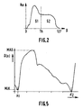
- This threshold Th is determined with reference to FIG. constructing a histogram Hm (G) of each amplitude image 111 as shown by way of example in FIG.
- the histogram Hm (G) represents the number Hm of the points of the image having each gray level G present in the image, for example 0 to 127.
- the histogram Hm (G) is divided into two parts of equal weight S1 and S2.
- Th threshold corresponds to the gray level at the border between parts S1 and S2.
- Th ⁇ S p
- ⁇ is a coefficient of proportionality that depends on the gain used for the acquisition of the ultrasound image.
- the threshold Th is applied on the amplitude images as shown in FIG. to provide images binaries as shown in FIG. 3B.
- An image such as that of FIG.3B does not yet make it possible to determine the boundaries parietal, that is to say the borders 3a and 3b as shown in FIG. 4A schematically between the walls 2a, 2b and the opening 7 of the artery 6.
- the binary image obtained where the inside of the artery is black and the outside is white, shows a black / white transition, corresponding to these boundaries parietal, which is far from smooth.
- the operation of the POST-TREATMENT 130 then comprises a step of detecting the internal parietal borders 3a, 3b.
- P R is defined by: P R ⁇ X R , [Z 1 (X R +1) + Z 2 (X R 1)] / 2 ⁇
- Two curves Z 1 (X) and Z 2 (X) corresponding to the internal parietal boundaries 3a, 3b lower and upper are then available. These curves are themselves filtered to eliminate significant local discontinuities remaining parietal boundaries, as it appeared for example in FIG.3C.
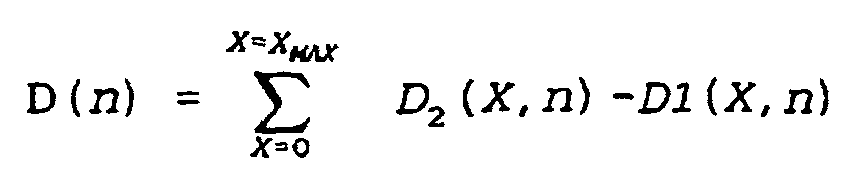
- the POST-PROCESSING operation 130 still includes a determination of the parietal displacement values D1 and D2.
- the sums ⁇ correspond first to averaging velocities in the thickness of the wall arterial, so in the chosen thickness of 1 mm, then at a temporal integration of incremental displacements between each image recurrence.
- the temporal integration must be corrected by a constant determining the reference position corresponding to an initial moment coinciding with the moment of commencement of the cardiac cycle, where the artery is supposed to be unexpanded, that is to say show null parietal movements.
- reference time the start time of the cardiac cycle
- the reference time is determined by the analysis of the temporal variations of the arterial dilatation averaged along the longitudinal arterial axis (OX).
- the curve D (n) is presented in FIG.
- the abscissae n1 and n2 must be identified as beginnings of cardiac cycles by an automatic method.
- the minimum MIN and maximum MAX values are detected, and a function f (n) is calculated from these detections.
- f (n) 1
- the function f (n) validates the curve segments D (n) less than a predetermined value D 0 .
- minimum values of D (n) are determined and the corresponding instants, n1, n2 are stored. These instants n1 and n2 are supposed to correspond to the beginnings of successive cardiac cycles.
- d1 (X, n) D1 (X, n) -D1 (x, n1) - (N-n1) (N2-n1) [D1 (X, n2) -D1 (X, n1)]
- d2 (X, n) D2 (X, n) -D2 (x, n1) - (N-n1) (N2-n1) [D2 (X, n2) -D2 (X, n1)]
- the parietal displacements D1 and D2 can be represented relative to reference positions corresponding to the temporal landmarks of the beginnings of heart cycles.
- operation 140 performs graphical inlay of curves corresponding to displacements parietal D1 and D2 and reference lines REF1 and REF2 on standard ultrasound images or intensity images I (X, Z, n) which are stored in the CINE-LOOP memory.
- the reference lines REF1 and REF2 are derived from parietal border curves extracted from amplitude images and corresponding to the beginning of the first cardiac cycle of the image sequence, and are calculated by a regression method linear known per se.
- each image n of the sequence is provided with reference lines REF1, REF2 and lines DP1, DP2 representing the displacement of each point of the borders parietal at the moment n.
- the images of the sequence are again stored in CINE-LOOP memory to be displayed on the display device 50.
- the practitioner can evaluate qualitatively and quantitatively the distortions or non-distortions of the lines graphs simulating the displacements of the walls and deduce the presence and severity of stenoses, or elastic defects, related arterial walls of the underlying ultrasound image.
- Visualization of arterial dilation in real time nevertheless delayed by one second in order to identify the moments corresponding to the beginnings of cardiac cycle and correct the displacements, also makes it possible to optimize the position of the probe ultrasound to obtain a cutting plane passing through the axis arterial parallel to OX.
- the invention has been described above with respect to the ultrasound signal processing but it can be applied to the processing of signals of different nature: electrical, electromagnetic, etc.
Description
L'invention concerne un procédé de traitement de signaux,
comprenant des étapes de:
L'invention trouve son application dans l'industrie de l'imagerie médicale échographique.The invention finds its application in the industry of ultrasound medical imaging.
Le domaine de l'invention est celui des outils d'aide au diagnostic en médecine cardio-vasculaire pour l'étude non invasive des anomalies des artères. Parmi les anomalies, le praticien cherche particulièrement à étudier les sténoses. Un critère de diagnostic d'une sténose est une réduction brusque du diamètre d'une artère. Un autre critère est la vitesse du sang à la sortie de la sténose. Il apparait d'après des études que le comportement du sang dans une artère sténosée ne suit pas la loi d'écoulement des fluides de Bernouilli, en ce sens que cette vitesse n'augmente pas conformément à cette loi dans la zone où le diamètre de l'artère diminue. Au contraire, la vitesse du sang diminue dès que le diamètre de l'artère atteint un seuil de rétrécissement. Il en résulte que, petit à petit, l'artère se bouche complètement dans la zone d'abord seulement étrécie, créant finalement un phénomène de thrombose. Par ailleurs, des plaques rigides peuvent aussi apparaítre dans l'épaisseur des parois des artères. Ces plaques créent des changements d'élasticité des parois et provoquent des tensions si importantes à l'intérieur de la parois que, durant le cycle cardiaque, la paroi artérielle est déformée à la limite de la rupture et peut émettre des emboles. Il existe donc dans le domaine médical, une nécessité de disposer de moyens non invasifs d'étude des artères, et en particulier des artères lésées, pour chercher une explication à ce comportement.The field of the invention is that of tools for assisting diagnosis in cardiovascular medicine for noninvasive study abnormalities of the arteries. Among the anomalies, the practitioner seeks especially to study stenoses. A diagnostic criterion stenosis is a sharp reduction in the diameter of an artery. A Another criterion is the speed of blood at the exit of the stenosis. he appears from studies that the behavior of blood in a stenotic artery does not follow the fluid flow law of Bernouilli, in that this speed does not increase according to to this law in the zone where the diameter of the artery decreases. At contrary, the speed of blood decreases as soon as the diameter of the artery reaches a narrowing threshold. It follows that, little by little, the artery gets completely clogged in the area first only narrowing, finally creating a phenomenon of thrombosis. By elsewhere, rigid plates may also appear in the thickness of the walls of the arteries. These plates create wall elasticity changes and cause tension if important inside the walls that during the cycle heart, the arterial wall is distorted at the edge of the rupture and may emit emboli. So there is in the field medical, a need to have non-invasive means of study arteries, and particularly injured arteries, to seek explanation to this behavior.
Un procédé de traitement de signaux échographiques et un dispositif pour mettre en oeuvre ce procédé sont déjà connus du brevet US 9,630,612 (UCHIDA et al.). Ce document décrit un procédé appliqué à des images d'intensité d'un vaisseau sanguin, qui représentent ce vaisseau en coupe transversale. Ce procédé comprend des étapes pour déterminer le diamètre du vaisseau sur une ligne échographique passant par le centre du vaisseau en coupe transversale. En particulier, les images d'intensité sont munies d'une ligne graphique, appelée curseur, qui matérialise la ligne échographique diamétrale et de repères ponctuels positionnés à l'intersection de cette ligne diamétrale et des parois internes du vaisseau. Ce procédé comprend aussi des étapes de tracking des points diamétraux pour repositionner les repères ponctuels d'une image d'intensité à une autre image d'intensité d'une séquence d'images.An ultrasound signal processing method and a device for carrying out this process are already known from US Patent 9,630,612 (UCHIDA et al.). This document describes a process applied to intensity images of a blood vessel, which represent this vessel in cross section. This process comprises steps to determine the diameter of the vessel on a line ultrasound passing through the center of the vessel in section cross. In particular, intensity images are provided a graphic line, called a cursor, which materializes the line diametric ultrasound and point markers positioned at the intersection of this diametrical line and the internal walls of the vessel. This method also includes steps for tracking diametrical points to reposition the punctual markers of a intensity image to another intensity image of a sequence images.
Une méthode de traitement d'image pour déterminer les bords d'un organe est déjà connue du brevet US 5,360,006. Ce document concerne une méthode pour générer les bords d'un organe substantiellement circulaire, et pour déterminer le centre du cercle. A cet effet un modèle elliptique est construit, puis est utilisé pour filtrer une image d'ultrasons. Ce modèle est centré au point centre du cercle préalablement déterminé. Ce modèle est ensuite utilisé sur deux images successives, pour déterminer des histogrammes correspondants. Les histogrammes sont alors utilisés pour déduire les changements de position des bords circulaires de l'organe étudié.An image processing method to determine the edges of an organ is already known from US Patent 5,360,006. This document relates to a method for generating the edges of an organ substantially circular, and to determine the center of the circle. For this purpose an elliptical model is constructed and then is used to filter an ultrasound image. This model is centered at center point of the circle previously determined. This model is then used on two successive images, to determine corresponding histograms. The histograms are then used to infer the positional changes of the circular edges of the organ studied.
Un procédé de traitement de signaux échographiques et un dispositif pour mettre en oeuvre ce procédé sont déjà connus de la demande de brevet européen publiée sous le numéro EP 0674185, sous priorité du 25-03-94 (BONNEFOUS). Le procédé connu comprend l'acquisition de données à la sortie d'un système échographique sous forme de signaux hautes fréquences acoustiques sortant d'une sonde, la formation d'une image échographique formée de lignes de pixels correspondant aux lignes de tir de la sonde, et l'application sur les signaux d'une opération de corrélation temporelle fournissant des vitesses de déplacement de structures dans l'image échographique.An ultrasound signal processing method and a device for implementing this method are already known from the European patent application published under the number EP 0674185, under priority of 25-03-94 (BONNEFOUS). The known method comprises the acquisition of data at the output of an ultrasound system under form of acoustic high frequency signals coming out of a probe, the formation of an ultrasound image formed of lines of pixels corresponding to the firing lines of the probe, and the application on the signals of a time correlation operation providing speeds of displacement of structures in the image Ultrasound.
En particulier le procédé proposé comprend une étape d'identification de la position d'une artère en coupe, une étape de calcul de la vitesse radiale des parois de l'artère le long des lignes de tir de la sonde échographique utilisée dans la formation de l'image, une étape de calcul de l'amplitude des mouvements propres de chaque paroi de l'artère le long des lignes de tir et une étape de calcul de la dilatation de l'artère le long des lignes de tir.In particular, the proposed method comprises a step identification of the position of a sectional artery, a step of calculation of the radial velocity of the walls of the artery along the firing lines of the ultrasound probe used in training of the image, a stage of calculation of the amplitude of the movements of each wall of the artery along the lines of fire and a step of calculating the dilation of the artery along the lines of shoot.
Un problème technique réside dans le fait que l'exploitation de
ces données n'est pas facile, si bien que le praticien qui utilise
l'image échographique comme outil d'aide au diagnostic peut
difficilement en tirer profit directement.
Ce problème est résolu au moyen d'un procédé selon la revendication
1. Ce procédé présente l'avantage de rendre ces données facilement
accessibles, compréhensibles et exploitables par la praticien.A technical problem lies in the fact that the exploitation of these data is not easy, so that the practitioner who uses the ultrasound image as a diagnostic aid tool can hardly benefit directly.
This problem is solved by means of a method according to
Un appareil d'échographie ultrasonore comprenant un dispositif
d'aide au diagnostic selon la revendication 7 permet de mettre en
oeuvre ce procédé. Cet appareil présente l'avantage de fournir une
aide au diagnostic des anomalies des parois des artères en procurant
un outil de visualisation du fonctionnement d'une artère au
voisinage d'une zone suspecte, durant un cycle cardiaque.
L'invention est décrite dans des mises en oeuvre particulières en
référence aux figures schématiques annexées dont la liste est donnée
ci-après :
- la FIG.1 représente sous forme de blocs fonctionnels un dispositif de détermination de données graphiques associé à un appareil échographique ;
- la FIG.2 représente un histogramme Hm de l'image échographique en niveaux de gris G ;
- les FIG.3A à 3C illustrent une méthode de binarisation de l'image échographique ;
- les FIG.4A à 4C illustrent une méthode de construction de lignes graphiques superposées à une image échographique de niveaux de gris ;
- la FIG.5 montre une courbe des déplacements pariétaux D(n) d'une artère en fonction d'instants n, dans le temps.
The invention is described in particular implementations with reference to the attached schematic figures, the list of which is given below:
- FIG. 1 represents, in the form of functional blocks, a device for determining graphic data associated with an ultrasound apparatus;
- FIG. 2 represents a histogram Hm of the grayscale echographic image G;
- FIGS. 3A to 3C illustrate a method of binarizing the ultrasound image;
- FIGS. 4A to 4C illustrate a method of constructing graphical lines superimposed on a grayscale ultrasound image;
- FIG. 5 shows a curve of the parietal displacements D (n) of an artery as a function of moments n, in time.
En référence à la FIG.1, un appareil d'échographie
ultrasonore 1 est muni d'un dispositif d'aide au diagnostic 100. Ce
dispositif composite 1,100 constitue un système de construction et
d'affichage d'une séquence d'images dans laquelle des graphismes
sont superposés à des images échographiques standards. Ces
graphismes représentent schématiquement une partie mobile d'un
organe présent dans les images de la séquence, et sont arrangés pour
reproduire l'évolution du mouvement de la partie de l'organe, avec
une amplitude amplifiée, sur une plage de temps prédéterminée.With reference to FIG. 1, an ultrasound
Ce dispositif composite 1,100 est décrit dans une application spécifique d'aide au diagnostic de lésions des parois artérielles.This composite device 1,100 is described in a specific application of aid for the diagnosis of wall lesions Arterial.
En référence à la FIG.1 et à la FIG.4A, un appareil échographique 1 met en oeuvre pour son fonctionnement, une sonde 10 en contact avec le milieu observé. Cette sonde 10 émet, par tirs périodiques, des signaux ultrasonores vers le milieu exploré, selon une direction notée OZ, et reçoit, selon la même direction OZ, des échos renvoyés par les obstacles rencontrés dans le milieu. Dans l'application envisagée, cette sonde est composée de transducteurs ultrasonores assemblés selon une barrette linéaire d'orientation notée OX. A chaque transducteurs correspond une ligne de tir.With reference to FIG. 1 and FIG. 1 uses, for its operation, a probe 10 in contact with the environment observed. This probe 10 emits, by shots periodicals, ultrasonic signals to the explored medium, according to OZ, and receives, according to the same OZ direction, echoes returned by obstacles encountered in the middle. In the intended application, this probe is composed of transducers ultrasound assembled according to a linear array of orientation noted OX. Each transducer has a shooting line.
Dans l'étape d'émission, le milieu est exploré selon les
directions des lignes de tir. En réception, l'image de chaque ligne
de tir est formée, en tenant compte du temps de propagation dans le
milieu et de l'amplitude des échos retrodiffusés par les obstacles
rencontrés sur la ligne de tir considérée. De préférence, pour
obtenir une bonne résolution de cette image les tirs ultrasoniques
sont focalisés en émission et en réception. A cet effet, un petit
réseau de transducteurs ultrasonores adjacents est utilisé pour
émettre et recevoir un faisceau ultrasonore focalisé
électroniquement sur un point situé sur la ligne de tir centrale du
petit réseau et à une profondeur prédéterminée Z dans le milieu. Une
image d'intensité I(X,Z) 21 est donc formée par balayage de chaque
ligne de tir de la sonde. L'opération 20 de focalisation et balayage
de la sonde 10, fournit donc des signaux hautes fréquences
acoustiques S(X,Z,n) qui permettent de construire, en fonction de
l'instant n, par une opération 30, une séquence d'images d'intensité
I(X,Z,n), où n est le numéro de l'image de la séquence. Les images
peuvent être soit affichées directement sur un moniteur 50, soit
stockées dans une mémoire d'image appelée CINE-LOOP 40, d'où elles
peuvent être rappelées quand besoin est, pour un nouvel affichage.In the transmission step, the medium is explored according to the
directions of the shooting lines. In reception, the image of each line
is formed, taking into account the propagation time in the
middle and amplitude of echoes backscattered by obstacles
encountered on the firing line considered. Preferably, for
get a good resolution of this image the ultrasonic shots
are focused in transmission and reception. For this purpose, a small
network of adjacent ultrasound transducers is used to
send and receive a focused ultrasound beam
electronically on a point on the central firing line of the
small network and at a predetermined depth Z in the middle. A
intensity image I (X, Z) 21 is thus formed by scanning each
firing line of the probe. The focusing and scanning operation
of the probe 10, thus provides high frequency signals
acoustics S (X, Z, n) that allow to build, according to
the instant n, by an
En référence à la FIG.1, un dispositif 100 de traitement
des signaux hautes fréquences fournis par l'opération 20 de
focalisation et balayage de la sonde, est associé à l'appareil
échographique 1, pour permettre son fonctionnement en mode
graphique. Ce mode graphique permet d'observer le comportement d'une
artère, et particulièrement des parois artérielles, à chaque instant
d'un cycle cardiaque, lorsque l'onde pulsatile se propage à
l'intérieur de l'artère considérée comme un guide d'ondes.With reference to FIG. 1, a
Sous effet de l'onde pulsatile du sang dans l'artère, durant un cycle cardiaque, les parois de l'artère sont soumises à un mouvement périodique radial dont l'amplitude et la vitesse peuvent être déterminées. Selon l'état des parois artérielles, les variations de pression induites par l'onde pulsatile créent soit une dilatation artérielle homogène, soit un mouvement pariétal distordu.Under the effect of the pulsatile wave of the blood in the artery, during a cardiac cycle, the walls of the artery are subjected to a radial periodic motion whose amplitude and velocity can be determined. Depending on the condition of the arterial walls, pressure variations induced by the pulsatile wave create either a homogeneous arterial dilatation, ie a distorted parietal movement.
Le dispositif 100 de traitement des signaux ultrasonores
comprend un processeur qui met en oeuvre des étapes de construction
d'une séquence d'images incluant des lignes graphiques reproduisant
les mouvements des frontières pariétales internes d'un tronçon
d'artère exploré par l'appareil échographique, en chaque point
balayé des frontières pariétales, et à chaque instant n d'un cycle
cardiaque, selon une échelle d'amplification spatiale prédéterminée.The
Ces lignes graphiques permettent de fonder le diagnostic
de lésions pariétales sur la forme et sur l'amplitude des
déplacements pariétaux, au lieu de fonder ce diagnostic seulement
sur la vitesse d'écoulement du sang dans l'artère, et/ou sur le
diamètre moyen de la lumière de l'artère dans la région lésée. Le
dispositif de traitement de signaux ultrasonores 100 est un outil
d'aide au diagnostic qui permet de détecter une lésion pariétale
d'artère, et d'en apprécier la gravité par l'étude des déplacements
des frontières pariétales par rapport à la normale. Le dispositif de
traitement de signaux ultrasonores 100 associé à l'appareil
échographique 1 met en oeuvre des étapes de construction et
d'affichage d'une séquence d'images échographiques standards en
niveaux de gris ou intensité, munies de ces lignes graphiques
superposées ou incrustées reproduisant les positions des frontières
pariétales internes de l'artère à chaque instant n d'un cycle
cardiaque et donc simulant les mouvements de ces frontières
pariétales soumises à l'onde pulsatile durant le cycle cardiaque,
d'une manière facilement exploitable par un praticien.These graphic lines make it possible to base the diagnosis
of parietal lesions on the shape and amplitude of
parietal shifts, instead of basing this diagnosis only
on the rate of flow of blood in the artery, and / or on the
average diameter of the artery lumen in the injured region. The
ultrasonic
En référence à la FIG.4A, qui est une image d'intensité
échographique standard schématisée, l'observation du comportement
des parois artérielles, conduit à l'exploration du milieu par la
sonde échographique 10 de telle manière que l'artère est balayée
longitudinalement parallèlement à OX pour fournir des images
d'intensité de l'artère en coupe longitudinale en permettant la
visualisation des parois antérieure 2a et postérieure 2b. La
direction de la barrette de transducteurs est représentée par la
direction OX, et la direction des lignes de tirs est représentée par
la direction OZ. Donc l'image échographique est balayée selon des
lignes de tir de direction OZ, qui sont les colonnes de l'image.Referring to FIG.4A, which is an intensity image
schematic standard ultrasound, behavioral observation
arterial walls, leads to the exploration of the environment by the
ultrasound probe 10 so that the artery is scanned
longitudinally parallel to OX to provide images
intensity of the artery in longitudinal section allowing
visualization of the
Le comportement de l'artère doit être observé sur un
cycle cardiaque complet. Donc, une séquence d'un nombre N d'images
couvrant une plage de temps au moins égale à un cycle cardiaque doit
être construite, où N représente un nombre 1 ≤ N.The behavior of the artery must be observed on a
complete cardiac cycle. So, a sequence of N number of images
covering a time range at least equal to one cardiac cycle must
be constructed, where N represents a
Le comportement de l'artère doit être observé relativement aux différentes phases du cycle cardiaque. Donc, un repère temporel commun à la séquence d'image et au cycle cardiaque doit être identifié.The behavior of the artery must be observed relative to the different phases of the cardiac cycle. So, a temporal marker common to the image sequence and the cardiac cycle must be identified.
Le comportement de l'artère doit être observé
relativement à une norme. Donc, des droites graphiques de référence
spatio-temporelle REF1, REF2 doivent être définies et incrustées sur
les images de la séquence, où n représente un nombre 1 ≤ n ≤ N.The behavior of the artery must be observed
in relation to a standard. So, graphic reference rights
spatio-temporal REF1, REF2 must be defined and embedded on
the images of the sequence, where n represents a
Le comportement de l'artère doit être observé de manière qualitative. Donc des lignes graphiques formées de points doivent donner les déplacements des parois artérielles sur chaque ligne de tir d'une image de la séquence et en outre donner les déplacements à chaque instant n du cycle cardiaque, c'est-à-dire dans chaque image n de la séquence.The behavior of the artery must be observed qualitative. So graphic lines formed of points must give the displacements of the arterial walls on each line of shot of an image of the sequence and further give the displacements to every moment n of the cardiac cycle, that is to say in each image n of the sequence.
Le comportement de l'artère doit être observé de manière quantitative. Donc les lignes graphiques doivent donner les déplacements par rapport aux droites de référence selon une échelle spatiale prédéterminée.The behavior of the artery must be observed quantitative. So the graphic lines have to give the displacements relative to the reference lines according to a scale predetermined space.
Pour le tracé de ces lignes graphiques reproduisant le
mouvement des parois artérielles, la vitesse et l'amplitude du
déplacement des parois doivent être déterminées. Cette opération est
effectuée dans le processeur 100 par une opération de corrélation
temporelle 120.For the drawing of these graphic lines reproducing the
movement of the arterial walls, the speed and amplitude of the
displacement of the walls must be determined. This operation is
performed in the
Dans cette opération de corrélation temporelle 120, les
échos ultrasoniques successifs produits par les structures
biologiques en mouvement, et générés dans l'étape précédente de
focalisation et balayage 20, sont comparés au moyen de leur fonction
de corrélation. Le déplacement des structures biologiques, d'une
émission ultrasonique à la suivante est estimée en tenant compte du
déplacement du pic de corrélation correspondant au retard induit à
la réception par ce déplacement.In this
L'opération de corrélation 120 fournit des mesures de
vitesse de tous les objets balayés, sous la forme d'images
bidimensionnelles de vitesses V(X,Z,n) notées 121 et stockées dans
une mémoire 122 appelée MEM1.The
L'objet du dispositif d'aide au diagnostic 100 étant
fondé sur l'observation des mouvements pariétaux, une localisation
des vitesses correspondant aux mouvements pariétaux est donc
effectuée. Cette localisation est effectuée par une méthode 130 de
traitement d'images appelée POST-TRAITEMENT comprenant une étape de
détermination des localisations des parois artérielles dans des
images d'amplitude d'échos A(X,Z,n) correspondantes notées 111,
déterminées par une opération 110 de mesures d'amplitudes d'échos et
stockées dans une mémoire 112 notée MEM2, et comprenant une étape de
report des localisations des parois artérielles dans les images des
vitesses 121.The object of the
Des vitesses spatiales pariétales moyennes instantanées sont alors déterminées et intégrées dans le temps pour fournir les déplacements pariétaux correspondants.Instantaneous mean parietal space velocities are then determined and integrated over time to provide the corresponding parietal movements.
Des lignes graphiques construites dans l'opération 130,
simulant les déplacements pariétaux D1 et D2 respectivement
antérieur et postérieur sont incrustées dans une opération 140 dans
chaque image de la séquence d'images prélevée dans la mémoire CINE-LOOP,
puis stockée à nouveau dans la mémoire CINE-LOOP après
incrustation.Graphical lines constructed in
Une configuration échographique est spécialement
réalisée pour se trouver en conformité avec la plage des
déplacements pariétaux. Le tronçon d'artère étudié est balayé
bidimensionnellement en 20 aussi rapidement que possible et
l'opération de corrélation temporelle 120 est mise en oeuvre image
après image dans la séquence. La période de récurrence est prise
égale à la période d'image notée TFRAME. La plage des vitesses
radiales V des parois artérielles est liée à la période d'image
TFRAME, à la fréquence ultrasonique notée fo, et à la vitesse C de
propagation du son dans le milieu, par la formule suivante :
La vitesse pariétale maximale est de l'ordre de 10 mm/s.
Il en résulte qu'une période d'image doit être de l'ordre de :
Cette période d'image TFRAME correspond à un taux élevé de production d'images. Il en résulte que, pour chaque image, on n'aura pas recours à des transmissions multiples pour chaque ligne de tir de l'image échographique et qu'une seule focalisation sera utilisée en transmission. Dans le cas de l'application du dispositif 1,100 à l'observation de la vascularisation périphérique, ou à l'étude de l'artère carotide par exemple, où la profondeur de tir est inférieure à 4 cm, la fréquence de récurrence en transmission est environ 15 kHz. Le nombre de lignes de tir d'images peut être par exemple 68 avec un pas de balayage (distance entre lignes de tir) de 0,5 mm ; ou bien le nombre de lignes de tir d'images peut être 112 avec un pas de balayage de 0,25 mm. Ces caractéristiques permettent de visualiser un segment artériel de 28 mm. Le retard entre les signaux correspondant à chaque ligne de tir de l'image peut être ajusté en augmentant ou en décroissant le nombre de lignes de tir et le pas des lignes de tir.This frame period T FRAME corresponds to a high rate of production of images. As a result, for each image, there will be no multiple transmissions for each firing line of the ultrasound image and only one focus will be used in transmission. In the case of the application of the device 1,100 to the observation of the peripheral vascularization, or to the study of the carotid artery for example, where the depth of fire is less than 4 cm, the frequency of recurrence in transmission is about 15 kHz. The number of image firing lines can be for example 68 with a scanning pitch (distance between firing lines) of 0.5 mm; or the number of image firing lines can be 112 with a scanning pitch of 0.25 mm. These characteristics make it possible to visualize an arterial segment of 28 mm. The delay between the signals corresponding to each line of fire of the image can be adjusted by increasing or decreasing the number of lines of fire and the pitch of the lines of fire.
En référence à la FIG.1, l'opération de corrélation est
fondée sur le même principe que la méthode décrite dans le brevet
cité au titre d'état de la technique (EP 0 674 185 - BONNEFOUS).
Cependant, la présente opération de corrélation est réalisée entre
les images de la séquence d'images d'où il résulte qu'il est
nécessaire de disposer, en entrée du module effectuant l'opération
de corrélation, d'une mémoire 119 MEM3 assez importante. Cette
mémoire doit réaliser le retard nécessaire entre deux signaux
corrélés. En outre, pour améliorer l'exactitude des mesures, il est
préférable d'effectuer un moyennage de plusieurs fonctions de
corrélations. Typiquement le nombre de corrélations est Nc = 4.With reference to FIG. 1, the correlation operation is based on the same principle as the method described in the patent cited in the state of the art (EP 0 674 185 - BONNEFOUS). However, the present correlation operation is carried out between the images of the image sequence from which it follows that it is necessary to have, at the input of the module performing the correlation operation, a relatively
Une implémentation de mémoire utilisant le principe des
entrées selon les lignes, et des sorties selon les colonnes de la
mémoire est plus efficace qu'un moyennage de corrélations réalisé
dans l'opération de corrélation-même parce qu'il permet un calcul
simultané de toutes les corrélations. La mémoire 119 MEM3 doit
contenir les signaux 1bit des Nc + 1 images échographiques.
Toutefois la taille de cette mémoire MEM3 peut être réduite en
considérant seulement dans l'image une plage d'intérêt incluant
l'artère.A memory implementation using the principle of row-based inputs, and column-based outputs of the memory is more efficient than a correlation averaging performed in the correlation-same operation because it allows simultaneous calculation of all correlations. The
Pour un nombre 112 de lignes de tir d'images, sur une
profondeur d'examen de 20 mm, avec une fréquence ultrasonique fo =
7,5 MHz et une fréquence d'échantillonnage fS = 30 MHz, une image
correspond à 90 kbits. D'où il résulte que, avec les paramètres
donnés plus haut, 450 kbits sont nécessaires pour calculer une image
de vitesse. En conséquence, une mémoire de 256 ko, 50 ms, est
suffisante dans l'opération de corrélation.For a
L'opération de corrélation, menée à bien
substantiellement selon l'enseignement du document cité (EP
0674185), fournit des images 121 de vitesse V(X,Z,n). D'autre part
des images 111 d'amplitude d'écho A(X,Z,n) sont également
nécessaires, et sont obtenues par une opération de mesure
d'amplitude 110 décrite dans le même document cité.The correlation operation, carried out successfully
substantially according to the teaching of the cited document (EP
0674185), provides
Les mémoires 122 MEM1 et 112 MEM2 stockent
respectivement les résultats des opérations de corrélation 120 et de
mesure d'amplitude 110 qui sont les images de vitesses V(X,Z,n) et
les images d'amplitude d'écho A(X,Z,n) correspondantes. Il n'est pas
nécessaire de stocker la valeur des pics de corrélation.The
L'opération de POST-TRAITEMENT 130 est consacrée à
l'exploitation des résultats des opérations précédentes 110 et 120,
c'est-à-dire d'abord au calcul des vitesses pariétales. Les étapes
principales de cette opération 130 sont l'extraction et la
localisation des vitesses pariétales des images bidimensionnelles
des vitesses. Ces étapes sont mises en oeuvre en utilisant les
images d'amplitude 111 comme moyens de segmentation. Puis une étape
de moyennage spatial des vitesses pariétales est mise en oeuvre en
accumulant les vitesses pariétales d'une image à la suivante dans la
séquence de manière à obtenir les déplacements pariétaux.The POST-PROCESSING 130 operation is dedicated to
the exploitation of the results of the
Les déplacements résultants D1, D2 sont traités pour déterminer des instants de référence n1, n2 du cycle cardiaque où les déplacements doivent être mis à zéro. Une correction est appliquée aux courbes de déplacement pour assurer un comportement cyclique de l'artère, correspondant à une position de référence spatiale fixe et stable des parois à chaque début de cycle cardiaque.The resulting displacements D1, D2 are treated for determine instants of reference n1, n2 of the cardiac cycle where the trips must be set to zero. A correction is applied to the displacement curves to ensure behavior cyclic of the artery, corresponding to a reference position fixed and stable space of the walls at each beginning of the cycle heart.
Dans l'opération de POST-TRAITEMENT 130, un seuil Th
adaptable est calculé sur chaque image d'amplitude 111 A(X,Z,n) pour
réaliser l'identification de la frontière pariétale interne de
l'artère. Ce seuil Th est déterminé en référence à la FIG.2, en
construisant un histogramme Hm(G) de chaque image d'amplitude 111
telle que représentée à titre d'exemple sur la FIG.3A. L'histogramme
Hm(G) représente le nombre Hm des points de l'image ayant chaque
niveau de gris G présents dans l'image, par exemple 0 à 127.
L'histogramme Hm(G) est divisé en deux parties de poids égal S1 et
S2. Le seuil Th correspond au niveau de gris situé à la frontière
entre les parties S1 et S2.In the
Une implémentation possible est la suivante. On calcule
la surface de l'histogramme :

Le seuil Th est donné par :
Le seuil Th est appliqué sur les images d'amplitudes
telles que représentées sur la FIG.3A. pour fournir des images
binaires telles que représentées sur la FIG.3B. Une image telle que
celle de la FIG.3B ne permet pas encore de déterminer les frontières
pariétales, c'est-à-dire les frontières 3a et 3b telles que montrées
sur la FIG.4A schématiquement entre les parois 2a, 2b et l'ouverture
7 de l'artère 6. Ainsi sur la FIG.3B, l'image binaire obtenue, où
l'intérieur de l'artère est noir et l'extérieur est blanc, montre
une transition noir/blanc, correspondant à ces frontières
pariétales, qui est loin d'être lisse.The threshold Th is applied on the amplitude images
as shown in FIG. to provide images
binaries as shown in FIG. 3B. An image such as
that of FIG.3B does not yet make it possible to determine the boundaries
parietal, that is to say the
Un filtrage morphologique est alors appliqué sur l'image
binaire pour lisser les transitions et éliminer les tâches restant
dans la lumière de l'artère. Cette opération de filtrage
bidimensionnel est réduite à deux opérations de filtrage
monodimensionnel qui sont :
En référence à la FIG.3C, dans cette image binaire filtrée, les transitions correspondant aux frontières pariétales internes sont lissées.With reference to FIG. 3C, in this binary image filtered, the transitions corresponding to the parietal borders internal ones are smoothed.
L'opération du POST-TRAITEMENT 130 comprend ensuite une
étape de détection des frontières pariétales internes 3a, 3b. Un
point de référence noté :
Dans l'image de la FIG.3C, en partant de la position de référence (XR, ZR), le premier pixel non nul de coordonnées [XR, Z1(XR)] vers le haut de l'image sur la même ligne de tir est déterminé, puis de même, le premier pixel non nul de coordonnées [XR, Z2(XR)] vers le bas de l'image est déterminé. Ces deux points donnent les positions des frontières pariétales internes sur la ligne de tir considérée.In the image of FIG. 3C, starting from the reference position (X R , Z R ), the first non-zero pixel of coordinates [X R , Z 1 (X R )] towards the top of the image on the same firing line is determined, and similarly, the first non-zero pixel of coordinates [X R , Z 2 (X R )] down the image is determined. These two points give the positions of the internal parietal borders on the line of fire considered.
La même opération est appliquée aux autres lignes de
l'image : pour chaque ligne vers la droite et vers la gauche de
l'image, un point de référence PR sur la ligne est considéré, et les
premiers points vers le haut et vers le bas de l'image, non nuls,
sont détectés. Les points de référence considérés sont dérivés des
frontières précédemment déterminées.
Pour un incrément à droite, PR est défini par
For an increment on the right, P R is defined by
L'opération de POST-TRAITEMENT 130 comprend encore une
détermination des valeurs des déplacements pariétaux D1 et D2.The
Pour chaque ligne de coordonnée X de chaque image n de
la séquence d'images, les déplacements D1 et D2 sont calculés comme
suit :


Dans la formule ci-dessus, les sommes Σ correspondent d'abord à un moyennage des vitesses dans l'épaisseur de la paroi artérielle, donc dans l'épaisseur choisie de 1 mm, puis à une intégration temporelle des déplacements incrémentaux entre chaque récurrence d'image. L'intégration temporelle doit être corrigée par une constante déterminant la position de référence correspondant à un instant initial coïncidant avec l'instant de commencement du cycle cardiaque, où l'artère est censée être non dilatée, c'est-à-dire montrer des déplacements pariétaux nuls.In the formula above, the sums Σ correspond first to averaging velocities in the thickness of the wall arterial, so in the chosen thickness of 1 mm, then at a temporal integration of incremental displacements between each image recurrence. The temporal integration must be corrected by a constant determining the reference position corresponding to an initial moment coinciding with the moment of commencement of the cardiac cycle, where the artery is supposed to be unexpanded, that is to say show null parietal movements.
A cet effet, l'instant de début du cycle cardiaque
appelé instant de référence, ou repère temporel, doit être identifié
avec précision. L'instant de référence est déterminé par l'analyse
des variations temporelles de la dilatation artérielle moyennée le
long de l'axe artériel longitudinal (OX). Cette dilatation moyenne
D(n) est calculée par la différence des déplacements des deux parois
intégrée de la coordonnée X = 0 à la coordonnée X = Xmax
longitudinalement
La courbe D(n) est présentée sur la FIG.5. Les abscisses
n1 et n2 doivent être identifiées comme des commencements de cycles
cardiaques par une méthode automatique. A cet effet, sur la courbe
de la FIG.5, les valeurs minimale MIN et maximale MAX sont
détectées, et une fonction f(n) est calculée à partir de ces
détections. La fonction f(n) est définie par :
Autrement,
Un cycle cardiaque étant ainsi défini par les instants
n1 et n2, les courbes de déplacement D1(X,n) et D2(X,n) sont
corrigées de la manière suivante :
Après ces corrections, les déplacements pariétaux D1 et D2 peuvent être représentés par rapport à des positions de référence spatiale correspondant aux repères temporels de commencements des cycles cardiaques.After these corrections, the parietal displacements D1 and D2 can be represented relative to reference positions corresponding to the temporal landmarks of the beginnings of heart cycles.
En référence aux FIG.4B et 4C, l'opération 140 effectue
l'incrustation graphique de courbes correspondant aux déplacements
pariétaux D1 et D2 et de droites de référence notées REF1 et REF2
sur les images échographiques standards ou images d'intensité
I(X,Z,n) correspondantes qui sont stockées dans la mémoire CINE-LOOP.
Les droites de référence REF1 et REF2 sont dérivées des
courbes de frontières pariétales extraites des images d'amplitude et
correspondant au commencement du premier cycle cardiaque de la
séquence d'image, et sont calculées par une méthode de régression
linéaire connue en soi. With reference to FIGS. 4B and 4C,
En référence aux FIG.4B et 4C, chaque image n de la
séquence est munie de droites de référence REF1, REF2 et de lignes
DP1, DP2 représentant le déplacement de chaque point des frontières
pariétales à l'instant n. Les images de la séquence sont à nouveau
stockées dans la mémoire CINE-LOOP pour être affichées sur le
dispositif d'affichage 50.With reference to FIGS. 4B and 4C, each image n of the
sequence is provided with reference lines REF1, REF2 and lines
DP1, DP2 representing the displacement of each point of the borders
parietal at the moment n. The images of the sequence are again
stored in CINE-LOOP memory to be displayed on the
Lors du déroulement de la séquence sur le dispositif
d'affichage 50, le praticien peut évaluer qualitativement et
quantitativement les distorsions ou non-distorsions des lignes
graphiques simulant les déplacements des parois et en déduire la
présence et la gravité de sténoses, ou de défauts d'élasticité, liés
aux parois artérielles de l'image échographique sous-jacente.
La visualisation de la dilatation artérielle en temps réel,
néanmoins retardée d'une seconde pour pouvoir identifier les
instants correspondant aux débuts de cycle cardiaque et corriger les
déplacements, permet aussi d'optimiser la position de la sonde
échographique pour obtenir un plan de coupe passant par l'axe
artériel parallèle à OX.When running the sequence on the
L'invention a été décrite ci-dessus relativement au traitement de signaux échographiques mais elle peut être appliquée au traitement de signaux de nature différente : électrique, électromagnétique,... etcThe invention has been described above with respect to the ultrasound signal processing but it can be applied to the processing of signals of different nature: electrical, electromagnetic, etc.
Claims (9)
- A signal processing method which includes steps
of acquiring (20) data sets based on a series of echographic signals that relate to an organ that has moving wall parts, these data sets being acquired periodically over a predetermined time range; and
of constructing (30, 100) sequences of two-dimensional intensity images (I(X, Z, n)) on the basis of these data sets;
characterized in that the acquisition and construction steps comprise the formation of a sequence of intensity images that represents the object in longitudinal section with longitudinal walls in the two-dimensional images; and
characterized in that this method further includes construction steps of constructing corresponding two-dimensional image sequences of graphical representations of said longitudinal walls, including:one or various graphics line(s) which dynamically reproduce at a given scale the transversal and longitudinal movements of said longitudinal wall part(s) of the organ, andone or more graphics spatio-temporel marker lines; andsuperpositioning of said graphics lines of said longitudinal walls in the two-dimensional intensity images in longitudinal section. - A method as claimed in claim 1, in which in the construction step
of constructing corresponding image sequences of graphical representations, the longitudinal graphics lines are constructed based on the processing of information of velocities of displacement, of localization, and of displacement values of said longitudinal wall parts in transversal and longitudinal movements. - A method as claimed in one of the claims 1 or 2, in which the graphics marker lines represent the longitudinal walls (3a, 3b) during movements of the organ in a reference position (REF1, REF2) which form the spatio-temporal marker and/or in their amplified movement (DP1, DP2) at the given scale.
- A method as claimed in one of the claims 1 to 3 in which the organ (6) is an artery segment examined along its longitudinal axis (OX), and the moving wall parts (3a, 3b) of said organ, diagrammatically shown by one or more graphics lines, are the internal parietal boundaries of said artery segment.
- A method as claimed in claim 4, comprising in step (100) of constructing graphics lines including the operations of:storage (40) of the intensity images in a read/write memory (CINE-LOOP (R),correlation (120), to produce a sequence of velocity images [V(X,Z,n)] of the parietal boundaries of the artery segment,measurement (110) of the amplitude of the echographic signals, to supply a sequence of corresponding amplitude images [A(X,Z,n)],post-processing (130), including determination of the locations of the internal parietal boundaries [Z1(X), Z2(X)] in the amplitude images [A(X,Z,n)], a transfer of the locations of said parietal boundaries to the corresponding velocity images [V(X,Z,n)], and a construction of graphics lines on the basis of the locations of said parietal boundaries,and superpositioning of said graphics lines in the intensity images [I(X,Z,n)], to supply a sequence of superimposed intensity images which include graphics lines reproducing the movements of the internal parietal boundaries of said longitudinally examined artery segment, at parietal boundary points, and at the N instants of a cardiac cycle forming the time interval, according to a predetermined spatio-amplification scale.
- A method as claimed in claim 5, in which the post-processing operation (130) comprises a step of determining the displacements [D1(X,n), D2(X,n)] of the parietal boundaries on the basis of the radial velocities [V(X,Z,n)] of said parietal boundaries, including determining a correction constant for the parietal displacements, yielding a reference position that corresponds to a starting instant of a cardiac cycle, representing said temporal marker, and a step of determining the location of the parietal boundaries, including digitization of the amplitude images (A(X,Z,n)), and determination of the boundary points as the transition points according to a threshold (Z1(X), Z2(X)) between the points inside (7) the artery, in the digitized images, and the other points.
- An ultrasonic echographic apparatus (1), comprising a diagnostic tool carrying out an echographic signal processing method which is provided with a system (100) for constructing a sequence of intensity images [I(X,Z,n)] which represent an organ with longitudinal moving wall parts (6), in which longitudinal graphics lines (REF1, REF2; DP1, DP2) are superimposed and arranged to reproduce the evolution of the movements of said parts of the organ wall, with an amplified spatial amplitude, over a cardiac cycle, and also comprising a system for displaying images with a display system for displaying this sequence of superimposed intensity images.
- An apparatus as claimed in claim 7, in which the system (100) for the construction of superimposed intensity images includes modules for the construction of longitudinal graphics lines which diagrammatically represent one or more moving parts of the organ in a reference position and/or in its (their) transversal and longitudinal movements at each instant (n), spatially amplified according to a predetermined scale.
- An apparatus as claimed in claim 8, comprising a probe (10) with ultrasonic transducers which applies, by exploration of said organ (6), a series of standard echographic signals to a module (30) for the construction of a sequence of intensity images of said organ and to a read/write image memory (CINE-LOOP), in which apparatus the system (100) for constructing superimposed intensity images comprises:modules (MEM3, 120, MEM1) for carrying out a temporal correlation step and for supplying and storing a sequence of velocity images,modules (110, MEM2) for carrying out a step for measuring echographic amplitudes and for supplying and storing a corresponding sequence of amplitude images,a post-processing module (130) which localizes, on the basis of the corresponding velocity and amplitude images, the velocities on the moving parts of the organ, determines the corresponding displacements and constructs graphic curves of these displacements,a graphics superpositioning module (140) which superimposes said graphics curves on the images of the sequence stored in the image memory (CINE-LOOP 40) and, among these curves, reference curves (REF1, REF2) and displacement curves (DP1, DP2).
Applications Claiming Priority (2)
| Application Number | Priority Date | Filing Date | Title |
|---|---|---|---|
| FR9613191 | 1996-10-29 | ||
| FR9613191 | 1996-10-29 |
Publications (2)
| Publication Number | Publication Date |
|---|---|
| EP0840139A1 EP0840139A1 (en) | 1998-05-06 |
| EP0840139B1 true EP0840139B1 (en) | 2005-02-16 |
Family
ID=9497141
Family Applications (1)
| Application Number | Title | Priority Date | Filing Date |
|---|---|---|---|
| EP97203208A Expired - Lifetime EP0840139B1 (en) | 1996-10-29 | 1997-10-14 | Processing method for signals from objects having moving parts and echographic device carrying out the method |
Country Status (4)
| Country | Link |
|---|---|
| US (1) | US5938606A (en) |
| EP (1) | EP0840139B1 (en) |
| JP (1) | JPH10127638A (en) |
| DE (1) | DE69732511T2 (en) |
Families Citing this family (57)
| Publication number | Priority date | Publication date | Assignee | Title |
|---|---|---|---|---|
| US6050943A (en) | 1997-10-14 | 2000-04-18 | Guided Therapy Systems, Inc. | Imaging, therapy, and temperature monitoring ultrasonic system |
| WO2000036433A1 (en) * | 1998-12-15 | 2000-06-22 | Koninklijke Philips Electronics N.V. | Ultrasound process and apparatus for the determination of the location of a parietal surface in a tissue and of the absolute radius of an artery |
| US7840252B2 (en) * | 1999-05-18 | 2010-11-23 | MediGuide, Ltd. | Method and system for determining a three dimensional representation of a tubular organ |
| US9572519B2 (en) | 1999-05-18 | 2017-02-21 | Mediguide Ltd. | Method and apparatus for invasive device tracking using organ timing signal generated from MPS sensors |
| US7386339B2 (en) | 1999-05-18 | 2008-06-10 | Mediguide Ltd. | Medical imaging and navigation system |
| US8442618B2 (en) * | 1999-05-18 | 2013-05-14 | Mediguide Ltd. | Method and system for delivering a medical device to a selected position within a lumen |
| US9833167B2 (en) | 1999-05-18 | 2017-12-05 | Mediguide Ltd. | Method and system for superimposing virtual anatomical landmarks on an image |
| US7778688B2 (en) * | 1999-05-18 | 2010-08-17 | MediGuide, Ltd. | System and method for delivering a stent to a selected position within a lumen |
| US7343195B2 (en) * | 1999-05-18 | 2008-03-11 | Mediguide Ltd. | Method and apparatus for real time quantitative three-dimensional image reconstruction of a moving organ and intra-body navigation |
| WO2001041648A1 (en) * | 1999-12-07 | 2001-06-14 | Koninklijke Philips Electronics N.V. | Ultrasonic image processing method and system for displaying a composite image sequence of an artery segment |
| WO2001046713A1 (en) * | 1999-12-21 | 2001-06-28 | Koninklijke Philips Electronics N.V. | Ultrasonic image processing method and examination system for displaying an ultrasonic composite image sequence of an artery |
| US7914453B2 (en) | 2000-12-28 | 2011-03-29 | Ardent Sound, Inc. | Visual imaging system for ultrasonic probe |
| US20060079781A1 (en) * | 2002-12-18 | 2006-04-13 | Koninklijke Philips Electronics N.V. | Ultrasonic apparatus for estimating artery parameters |
| JP2006523485A (en) | 2003-04-15 | 2006-10-19 | コーニンクレッカ フィリップス エレクトロニクス エヌ ヴィ | Heart wall strain imaging |
| US8235909B2 (en) * | 2004-05-12 | 2012-08-07 | Guided Therapy Systems, L.L.C. | Method and system for controlled scanning, imaging and/or therapy |
| US9011336B2 (en) | 2004-09-16 | 2015-04-21 | Guided Therapy Systems, Llc | Method and system for combined energy therapy profile |
| US7393325B2 (en) | 2004-09-16 | 2008-07-01 | Guided Therapy Systems, L.L.C. | Method and system for ultrasound treatment with a multi-directional transducer |
| US7824348B2 (en) | 2004-09-16 | 2010-11-02 | Guided Therapy Systems, L.L.C. | System and method for variable depth ultrasound treatment |
| US10864385B2 (en) | 2004-09-24 | 2020-12-15 | Guided Therapy Systems, Llc | Rejuvenating skin by heating tissue for cosmetic treatment of the face and body |
| US8444562B2 (en) | 2004-10-06 | 2013-05-21 | Guided Therapy Systems, Llc | System and method for treating muscle, tendon, ligament and cartilage tissue |
| US8535228B2 (en) | 2004-10-06 | 2013-09-17 | Guided Therapy Systems, Llc | Method and system for noninvasive face lifts and deep tissue tightening |
| EP2279698A3 (en) | 2004-10-06 | 2014-02-19 | Guided Therapy Systems, L.L.C. | Method and system for non-invasive cosmetic enhancement of stretch marks |
| US7758524B2 (en) | 2004-10-06 | 2010-07-20 | Guided Therapy Systems, L.L.C. | Method and system for ultra-high frequency ultrasound treatment |
| US8066641B2 (en) | 2004-10-06 | 2011-11-29 | Guided Therapy Systems, L.L.C. | Method and system for treating photoaged tissue |
| US8690778B2 (en) | 2004-10-06 | 2014-04-08 | Guided Therapy Systems, Llc | Energy-based tissue tightening |
| US11883688B2 (en) | 2004-10-06 | 2024-01-30 | Guided Therapy Systems, Llc | Energy based fat reduction |
| US11235179B2 (en) | 2004-10-06 | 2022-02-01 | Guided Therapy Systems, Llc | Energy based skin gland treatment |
| US9827449B2 (en) | 2004-10-06 | 2017-11-28 | Guided Therapy Systems, L.L.C. | Systems for treating skin laxity |
| US20060111744A1 (en) | 2004-10-13 | 2006-05-25 | Guided Therapy Systems, L.L.C. | Method and system for treatment of sweat glands |
| US8133180B2 (en) | 2004-10-06 | 2012-03-13 | Guided Therapy Systems, L.L.C. | Method and system for treating cellulite |
| US9694212B2 (en) | 2004-10-06 | 2017-07-04 | Guided Therapy Systems, Llc | Method and system for ultrasound treatment of skin |
| US11207548B2 (en) | 2004-10-07 | 2021-12-28 | Guided Therapy Systems, L.L.C. | Ultrasound probe for treating skin laxity |
| US11724133B2 (en) | 2004-10-07 | 2023-08-15 | Guided Therapy Systems, Llc | Ultrasound probe for treatment of skin |
| JP4695188B2 (en) | 2005-04-25 | 2011-06-08 | アーデント サウンド, インコーポレイテッド | Method and apparatus for improving the safety of computer peripherals |
| US20080050001A1 (en) * | 2006-08-28 | 2008-02-28 | Digirad Corporation | Use of Subsets of the Acquired Data to Improve the Diagnostic Outcome in Cardiac SPECT Imaging |
| US9566454B2 (en) | 2006-09-18 | 2017-02-14 | Guided Therapy Systems, Llc | Method and sysem for non-ablative acne treatment and prevention |
| US8512248B2 (en) * | 2006-09-25 | 2013-08-20 | Tohoku University | Ultrasonograph that measures tissue displacements based on a reference point |
| JP2010526589A (en) | 2007-05-07 | 2010-08-05 | ガイデッド セラピー システムズ, エル.エル.シー. | Method and system for modulating a mediant using acoustic energy |
| US8764687B2 (en) | 2007-05-07 | 2014-07-01 | Guided Therapy Systems, Llc | Methods and systems for coupling and focusing acoustic energy using a coupler member |
| US20150174388A1 (en) | 2007-05-07 | 2015-06-25 | Guided Therapy Systems, Llc | Methods and Systems for Ultrasound Assisted Delivery of a Medicant to Tissue |
| EP2282675B1 (en) | 2008-06-06 | 2016-04-20 | Ulthera, Inc. | System for cosmetic treatment and imaging |
| KR20110101204A (en) | 2008-12-24 | 2011-09-15 | 가이디드 테라피 시스템스, 엘.엘.씨. | Methods and systems for fat reduction and/or cellulite treatment |
| US8715186B2 (en) | 2009-11-24 | 2014-05-06 | Guided Therapy Systems, Llc | Methods and systems for generating thermal bubbles for improved ultrasound imaging and therapy |
| JP5597455B2 (en) * | 2010-06-25 | 2014-10-01 | 株式会社東芝 | Ultrasonic diagnostic apparatus, ultrasonic image processing apparatus, and ultrasonic image processing program |
| US9504446B2 (en) | 2010-08-02 | 2016-11-29 | Guided Therapy Systems, Llc | Systems and methods for coupling an ultrasound source to tissue |
| US9149658B2 (en) | 2010-08-02 | 2015-10-06 | Guided Therapy Systems, Llc | Systems and methods for ultrasound treatment |
| US8857438B2 (en) | 2010-11-08 | 2014-10-14 | Ulthera, Inc. | Devices and methods for acoustic shielding |
| US8858471B2 (en) | 2011-07-10 | 2014-10-14 | Guided Therapy Systems, Llc | Methods and systems for ultrasound treatment |
| US9011337B2 (en) | 2011-07-11 | 2015-04-21 | Guided Therapy Systems, Llc | Systems and methods for monitoring and controlling ultrasound power output and stability |
| US9263663B2 (en) | 2012-04-13 | 2016-02-16 | Ardent Sound, Inc. | Method of making thick film transducer arrays |
| US9510802B2 (en) | 2012-09-21 | 2016-12-06 | Guided Therapy Systems, Llc | Reflective ultrasound technology for dermatological treatments |
| CN204637350U (en) | 2013-03-08 | 2015-09-16 | 奥赛拉公司 | Aesthstic imaging and processing system, multifocal processing system and perform the system of aesthetic procedure |
| WO2014146022A2 (en) | 2013-03-15 | 2014-09-18 | Guided Therapy Systems Llc | Ultrasound treatment device and methods of use |
| CA2944707C (en) | 2014-04-18 | 2023-01-24 | Ulthera, Inc. | Band transducer ultrasound therapy |
| ES2939604T3 (en) | 2016-01-18 | 2023-04-25 | Ulthera Inc | Compact ultrasonic device having an annular ultrasonic array peripherally electrically connected to a flexible printed circuit board |
| AU2017312527B2 (en) | 2016-08-16 | 2022-03-17 | Ulthera, Inc. | Systems and methods for cosmetic ultrasound treatment of skin |
| US11944849B2 (en) | 2018-02-20 | 2024-04-02 | Ulthera, Inc. | Systems and methods for combined cosmetic treatment of cellulite with ultrasound |
Citations (1)
| Publication number | Priority date | Publication date | Assignee | Title |
|---|---|---|---|---|
| EP0674185A1 (en) * | 1994-03-25 | 1995-09-27 | Laboratoires D'electronique Philips S.A.S. | Method and system for detecting and characterising a segment of a blood vessel by ultrasonic echography |
Family Cites Families (5)
| Publication number | Priority date | Publication date | Assignee | Title |
|---|---|---|---|---|
| EP0127157B2 (en) * | 1983-05-25 | 1993-06-09 | Aloka Co. Ltd. | Ultrasonic diagnostic apparatus |
| GB2156985B (en) * | 1984-04-02 | 1987-06-24 | Teltec Electronic Equip | Apparatus for measuring movable part-structures, eg blood vessels, within a living body |
| WO1991011146A1 (en) * | 1990-01-25 | 1991-08-08 | Commonwealth Scientific And Industrial Research Organisation | Ultrasonic method and apparatus for determination of vessel location and size |
| US5360006A (en) * | 1990-06-12 | 1994-11-01 | University Of Florida Research Foundation, Inc. | Automated method for digital image quantitation |
| JPH07241288A (en) * | 1994-03-04 | 1995-09-19 | Hitachi Ltd | Ultrasonic device |
-
1997
- 1997-10-14 EP EP97203208A patent/EP0840139B1/en not_active Expired - Lifetime
- 1997-10-14 DE DE69732511T patent/DE69732511T2/en not_active Expired - Lifetime
- 1997-10-24 US US08/957,202 patent/US5938606A/en not_active Expired - Fee Related
- 1997-10-27 JP JP9294552A patent/JPH10127638A/en active Pending
Patent Citations (1)
| Publication number | Priority date | Publication date | Assignee | Title |
|---|---|---|---|---|
| EP0674185A1 (en) * | 1994-03-25 | 1995-09-27 | Laboratoires D'electronique Philips S.A.S. | Method and system for detecting and characterising a segment of a blood vessel by ultrasonic echography |
Also Published As
| Publication number | Publication date |
|---|---|
| DE69732511D1 (en) | 2005-03-24 |
| JPH10127638A (en) | 1998-05-19 |
| EP0840139A1 (en) | 1998-05-06 |
| US5938606A (en) | 1999-08-17 |
| DE69732511T2 (en) | 2006-01-12 |
Similar Documents
| Publication | Publication Date | Title |
|---|---|---|
| EP0840139B1 (en) | Processing method for signals from objects having moving parts and echographic device carrying out the method | |
| JP6030825B2 (en) | Ultrasonic method for removing electromagnetic noise | |
| WO2013105197A1 (en) | Ultrasonic diagnosis device, and blood vessel detection method | |
| FR3039981A1 (en) | ||
| FR3072870A1 (en) | VISCOELASTIC ESTIMATION OF A FABRIC FROM SHEAR SPEED IN ULTRASONIC MEDICAL IMAGING | |
| FR2971695A1 (en) | VISCOELASTICITY MEASUREMENT USING PHASE AMPLITUDE MODULATED ULTRASONIC WAVE | |
| JP5265810B2 (en) | Ultrasonic diagnostic apparatus and in-vivo observation method | |
| FR2986701A1 (en) | SHEAR WAVE CHARACTERIZATION ON AXIS WITH ULTRASOUND | |
| FR2993768A1 (en) | SYSTEM AND METHOD FOR ECHOGRAPHIC IMAGING | |
| US20180296189A1 (en) | Methods, systems and computer program products for single track location shear wave elasticity imaging | |
| JP2016523167A (en) | Elastography measurement system and method | |
| FR2965934A1 (en) | MEMORIZATION MEDIUM, METHOD AND SYSTEM FOR TRANSVERSE WAVE RESOLUTION IN ULTRASONIC MEDICAL IMAGING | |
| FR2563991A1 (en) | APPARATUS FOR MEASURING PULSATILE ELEMENTARY STRUCTURES WITHIN A LIVING BODY | |
| FR3031448A1 (en) | ||
| FR3034975A1 (en) | ||
| JP2005152648A (en) | Method and system for motion-adaptive type spatial synthesis | |
| FR3047405A1 (en) | ||
| FR3003154A1 (en) | ESTIMATING THE FAT FRACTION USING ULTRASONICS FROM SHEAR WAVE PROPAGATION | |
| FR3050104A1 (en) | ||
| EP0674185A1 (en) | Method and system for detecting and characterising a segment of a blood vessel by ultrasonic echography | |
| EP3771927A1 (en) | Ultrasound system for detecting a flow of a fluid in a medium | |
| FR3046693A1 (en) | ||
| FR2986960A1 (en) | METHOD AND SYSTEM FOR VISUALIZATION OF ASSOCIATED INFORMATION IN ULTRASONIC SHEAR WAVE IMAGING AND COMPUTER-READABLE STORAGE MEDIUM | |
| FR3085760A1 (en) | Angles for ultrasonic shear wave imaging | |
| EP3022578B1 (en) | Method and device for mapping fibrous media |
Legal Events
| Date | Code | Title | Description |
|---|---|---|---|
| PUAI | Public reference made under article 153(3) epc to a published international application that has entered the european phase |
Free format text: ORIGINAL CODE: 0009012 |
|
| AK | Designated contracting states |
Kind code of ref document: A1 Designated state(s): DE FR GB NL |
|
| RAP3 | Party data changed (applicant data changed or rights of an application transferred) |
Owner name: KONINKLIJKE PHILIPS ELECTRONICS N.V. |
|
| 17P | Request for examination filed |
Effective date: 19981106 |
|
| AKX | Designation fees paid |
Free format text: DE FR GB NL |
|
| RBV | Designated contracting states (corrected) |
Designated state(s): DE FR GB NL |
|
| 17Q | First examination report despatched |
Effective date: 20020118 |
|
| GRAP | Despatch of communication of intention to grant a patent |
Free format text: ORIGINAL CODE: EPIDOSNIGR1 |
|
| GRAS | Grant fee paid |
Free format text: ORIGINAL CODE: EPIDOSNIGR3 |
|
| GRAA | (expected) grant |
Free format text: ORIGINAL CODE: 0009210 |
|
| AK | Designated contracting states |
Kind code of ref document: B1 Designated state(s): DE FR GB NL |
|
| PG25 | Lapsed in a contracting state [announced via postgrant information from national office to epo] |
Ref country code: NL Free format text: LAPSE BECAUSE OF FAILURE TO SUBMIT A TRANSLATION OF THE DESCRIPTION OR TO PAY THE FEE WITHIN THE PRESCRIBED TIME-LIMIT Effective date: 20050216 |
|
| REG | Reference to a national code |
Ref country code: GB Ref legal event code: FG4D Free format text: NOT ENGLISH |
|
| REF | Corresponds to: |
Ref document number: 69732511 Country of ref document: DE Date of ref document: 20050324 Kind code of ref document: P |
|
| GBT | Gb: translation of ep patent filed (gb section 77(6)(a)/1977) |
Effective date: 20050511 |
|
| REG | Reference to a national code |
Ref country code: GB Ref legal event code: 746 Effective date: 20050627 |
|
| NLV1 | Nl: lapsed or annulled due to failure to fulfill the requirements of art. 29p and 29m of the patents act | ||
| PLBE | No opposition filed within time limit |
Free format text: ORIGINAL CODE: 0009261 |
|
| STAA | Information on the status of an ep patent application or granted ep patent |
Free format text: STATUS: NO OPPOSITION FILED WITHIN TIME LIMIT |
|
| 26N | No opposition filed |
Effective date: 20051117 |
|
| PGFP | Annual fee paid to national office [announced via postgrant information from national office to epo] |
Ref country code: GB Payment date: 20071214 Year of fee payment: 11 |
|
| PGFP | Annual fee paid to national office [announced via postgrant information from national office to epo] |
Ref country code: FR Payment date: 20081028 Year of fee payment: 12 |
|
| GBPC | Gb: european patent ceased through non-payment of renewal fee |
Effective date: 20081014 |
|
| PG25 | Lapsed in a contracting state [announced via postgrant information from national office to epo] |
Ref country code: GB Free format text: LAPSE BECAUSE OF NON-PAYMENT OF DUE FEES Effective date: 20081014 |
|
| REG | Reference to a national code |
Ref country code: FR Ref legal event code: ST Effective date: 20100630 |
|
| PG25 | Lapsed in a contracting state [announced via postgrant information from national office to epo] |
Ref country code: FR Free format text: LAPSE BECAUSE OF NON-PAYMENT OF DUE FEES Effective date: 20091102 |
|
| REG | Reference to a national code |
Ref country code: DE Ref legal event code: R082 Ref document number: 69732511 Country of ref document: DE Representative=s name: VOLMER, GEORG, DIPL.-ING., DE |
|
| PGFP | Annual fee paid to national office [announced via postgrant information from national office to epo] |
Ref country code: DE Payment date: 20131230 Year of fee payment: 17 |
|
| REG | Reference to a national code |
Ref country code: DE Ref legal event code: R082 Ref document number: 69732511 Country of ref document: DE Representative=s name: VOLMER, GEORG, DIPL.-ING., DE Effective date: 20140331 Ref country code: DE Ref legal event code: R081 Ref document number: 69732511 Country of ref document: DE Owner name: KONINKLIJKE PHILIPS N.V., NL Free format text: FORMER OWNER: KONINKLIJKE PHILIPS ELECTRONICS N.V., EINDHOVEN, NL Effective date: 20140331 |
|
| REG | Reference to a national code |
Ref country code: DE Ref legal event code: R119 Ref document number: 69732511 Country of ref document: DE |
|
| PG25 | Lapsed in a contracting state [announced via postgrant information from national office to epo] |
Ref country code: DE Free format text: LAPSE BECAUSE OF NON-PAYMENT OF DUE FEES Effective date: 20150501 |