The present invention relates to an optical information storage medium
which exhibits a structural change between crystalline and amorphous structure
and a change in optical properties in accordance with the thermal history of
temperature rise and cooling by being subjected to laser light, this being
known as a phase change optical disk.
An optical disk recording method which uses a laser beam is capable of
high-capacity recording and, because of the non-contact nature and high speed
of this method, progress is being made in practical use of this method as
large-capacity memory.
Optical disks can be classified into three types: read-only type disks
such as those known as Compact Discs and laser discs, "write once" type disks
which can be appended to by a user, and rewritable disks which can be recorded
and erased repeatedly. Write many and rewritable optical disks are used as
external memory for computers, and as storage for document or image files.
There are two types of rewritable disks: a phase change type optical
disk which makes use of a phase change in a recording film, and a magneto-optical
disk which makes use of a change in the direction of magnetization of
perpendicular magnetization film.
Of these types, because the phase change optical disk not only does not
require an external magnetic field, but also enables easy overwriting, as well
as having the advantage of using the same playback method as a read-only disk,
it is expected that this type of disk will become the main type used for such
applications as overwritable digital video disks.
In the past, there has been a known type of so-called phase change
optical disk, which enabled overwriting and which used a recording film which
exhibited a phase changed between crystalline and amorphous phases in response
to exposure to light.
In a phase change optical disk, a laser light spot from a high-power
laser responsive to the information to be recorded on the recording film was
shone thereonto, thereby causing a localized rise in temperature in the
recording film, this bringing about a phase change between crystalline and
amorphous phases to effect recording by means of changing an optical constant
thereof, which can be read as differences in reflected light intensity using a
low-power laser beam when performing playback.
For example, in a phase change disk which uses a recording film having a
relatively slow crystallization time, the disk is turned and a laser beam is
shone onto the recording film formed on the disk, the temperature of the
recording film being raised to above the melting point thereof and, after the
laser light is passed therethrough, quick cooling is done to record information
as an amorphous condition in that part.
When erasing, the recording film temperature is held in a temperature
range within which crystallization is possible, this being a range which is
above the crystallization temperature and below the melting point, for a long
enough time to cause crystallization to progress, thereby causing the
crystallization of the recording film.
A known method for doing this that of shining an elliptical laser beam
which is elongated in the direction of movement. In the case in which new
information is recording as already recorded data is being erased, this being a
pseudo-overwriting system using two beams, an elliptical laser beam for the
purpose of erasing is positioned as to be shone ahead of the circular recording
laser beam
In a disk which uses an information recording film capable of high-speed
crystallization, a single laser beam which is collimated into a circular shape
is used.
A known method for doing this is that of changing the power of a laser
beam between two levels, thereby causing either crystallization or a change to
the amorphous phase.
That is, by shining a laser beam from a laser having sufficient power to
raise the temperature of the recording film to above the melting point, the
amorphous state is almost totally present when quick cooling is done.
In contrast to this, by shining a laser beam from a laser having power
such that the temperature of the recording film is above the crystallization
temperature and below the melting point, the part subjected to such light is
crystallized.
The recording film of a phase change optical disk is formed as a grown
film of a chalcogenide material such as GeSbTe, InSbTe, InSe, InTe, AsTeGe,
TeOx-GeSn, TeSeSn, SbSeBi, and BiSeGe or the like, in all cases this film being
formed by means of a resistive heating vacuum deposition method, electron beam
vacuum deposition method, or by sputtering or the like.
The condition of the recording film immediately after formation of the
film represents a type of amorphous state, and in order to form a recording
amorphous part thereof by performing recording onto the recording film, it
first necessary to perform initialization processing so as to change the overall
recording film to the crystallized condition. Then recording is done by
changing parts of this crystallized recording film to the amorphous state.
In a phase change optical disk in the past, there has been a method
proposed for mark edge recording, in which information is recorded at a
recording mark edge.
A disk configuration that is suitable for mark edge recording under the
assumption of use at high linear speed was proposed as having a configuration
which uses a transmission-type reflective film, and a silicon reflective film in
particular, (for example, in Japanese Unexamined Patent Publication (KOKAI) Nos.
4-102243, 8-77596, and 8-124218).
For use as an optical disk medium for use in low linear speed mark edge
recording, an example has been proposed which uses a metallic reflective film
(for example: Ishida et al, p. 70 of preprints of the Sixth Phase Change
Recording Research Symposium, November, 1994).
There is also known a track and groove recording method by which
recording is performed in both the depressed and protruding part of tracking
guide groove form on the substrate. By using this method, it is in principle
possible to achieve a two-fold increase in recording density in the track
direction, this enabling the achievement of high-density recording (for example,
Ohno et al, p. 114 of Fifth Phase Change Recording Research Symposium, November,
1993).
As described above, the combined use of mark edge recording and track
and groove recording is effective as a method of high-density recording. In
overwriting phase change recording, using the known type of recording in which
an amorphous mark is recorded in a crystallized part having a high reflectivity,
when performing mark edge recording of a reflectivity difference playback medium
in which there is a large difference in reflectivity between a crystallized
part and an amorphous part, because the medium does not have light passing
through it, the absorption factor of the crystallized part is quite a bit lower
than in the amorphous part, this causing the problem of not being able to
suppress distortion of the recorded edge when overwriting.
To solve the above-noted problem, a method of making the difference in
reflectivity between the crystalline part and the amorphous part small and
setting the optical phase difference therebetween so as to be large has been
proposed (for example, in Japanese Unexamined Patent Publication No. 2-73537,
Japanese Unexamined Patent Publication No. 2-113451, and Japanese Unexamined
Patent Publication No. 7-93804).
When this method is used, it is possible to make the absorption factor
of the crystalline part approximately the same as or larger than that of the
amorphous part, thereby enabling suppression of the distortion of the recording
mark to a small amount when overwriting.
However, in doubled track density recording, because of the necessary to
achieve a uniform signal level when performing land and groove playback, and
also it is required that the optical phase difference between the crystallized
part and the amorphous part should be set at around zero, by merely
establishing an optical phase difference and making the absorption factor of
the crystalline part the same level as or greater than that of the absorption
factor of the amorphous part, the level balance between land playback and groove
playback is upset, so that it is not possible to obtain a medium suitable for
good recording using a combination of mark edge recording and land and groove
recording.
The present invention was made to solve the above-noted problems, and
has as an object the provision of a phase change type optical disk that solves
the problems of a medium which uses a combination of mark edge recording and
land and groove recording, and which is capable of high-density recording while
maintaining overwriting characteristics for the prescribed mark edge recording.
SUMMARY OF THE INVENTION
To achieve the above-noted object, the present invention is a phase
change type optical disk which makes use of a reversible change in phase between
crystalline and amorphous to perform recording, playback, and erasing by means
of a change of phase in a recording film caused by subjecting it to laser light.
In this disk, a base protective film, a phase change recording film, an
upper protective film, a metallic reflective film, and a protective resin film
are sequentially laminated onto a substrate.
Onto the above-noted substrate a helical or concentrically circular
shaped guide groove in the shape of a groove and a land is priorly formed for
the purpose of laser beam tracking, phase change recording of information being
performed in both the groove and land of the above-noted guide groove, the
optical phase difference between the reflected laser light from the crystalline
condition and the amorphous condition of the above-noted phase change recording
film being established so as to be 180 degrees ±5 degrees.
In the present invention, the ratio of the light absorption factor of
the phase change recording film when it is in the crystalline condition to that
when it is in the amorphous condition is between 0.9 and 1.1.
In the present invention, with a wavelength of the laser light used of
λ, the optical depth of the guide groove that is formed in the substrate is
established so as to be from λ/9 to λ/6.
In the present invention the wavelength of the laser light used is in
the range from 635 nm to 650 nm, and the depth of the guide groove that is
formed in the substrate is established so as to be from 40 nm to 70 nm.
In the present invention, on a substrate made of polycarbonate, a base
protective film made of ZnS-SiO2, a phase change recording film having GeSbTe
as is main component, an upper protective film made of ZnS-SiO2, a metallic
reflective film having aluminum as its main component, and a protective resin
film which is cured by ultraviolet light are sequentially formed.
In addition, in the present invention, the metallic reflective film has
aluminum as its main component, and has the amount of added titanium established
so as to be from 0% to 2.0% by weight.
In the present invention, by making refinements of the constitution of
the phase change type optical disk, the optical phase of the reflected light
which accompanies an optical change in the recording film changes. Because of
this, the it is possible to obtain a playback signal without making the
difference in reflectivities of the crystalline parts and amorphous parts large.
Thus, it is easy to make the absorption factor at the recording film in
the case in which the recording film is in the crystalline condition large, and
this can be made either the same level as or larger than that in the case of an
amorphous part thereof, thereby achieving good overwriting characteristics with
mark edge recording.
In land and groove double-track recording, the optical phase difference
between the reflected laser light at a crystalline condition and amorphous
condition part of the land is established so as to be 180 degrees ±5 degrees.
At such an optical phase difference, when seen from reflected light, the
groove region of a groove during playback and land region of the groove during
playback are optically equivalent.
For this reason, it is substantially the same as the case in which the
optical phase difference between the reflected laser light from the crystalline
part of the recording film and the reflected laser light from the amorphous
part of the recording film is zero, this making it possible to achieve
consistency in the signal levels between land playback and groove playback.
As a resuit, it is possible to perform double track density recording
and mark edge recording.
Brief Description of the Drawings
Fig. 1 is a cross-sectional view of an embodiment of a phase change type
optical disk according to the present invention.
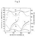
Fig. 2 is a drawing which shows the optical characteristics of another
phase change type optical disk according to the present invention.
Fig. 3 is a drawing which shows the crosstalk characteristics of phase
change type optical disk according to the present invention.
Detailed Description of the Preferred Embodiments
Embodiments of present invention are described below, with reference
being made to the relevant accompanying drawings.
Fig. 1 is a cross-sectional view which shows the configuration of a
phase change type optical disk according to the present invention. In this
drawing a phase change type optical disk 10 has a substrate 1, onto the
surface of which are sequentially formed a base protective film 2, a phase
change recording film 3, an upper protective film 4, a metallic reflective film
5, and a protective resin film 6.
Onto the above-noted substrate 1 a helical or concentrically circular
shaped guide groove (not shown in the drawing) in the shape of a groove and a
land is priorly formed for the purpose of laser beam tracking, phase change
recording of information being performed in both the groove and land of the
above-noted guide groove.
A disc-shaped glass or plastic is used as the substrate 1. As a material
for the base protective film 2 and the upper protective film 4, SiO2, Si3N4,
AlN, TiO2, ZnS, ZnS-SiO2 or the like is used. As the phase change recording film
3, a chalcogenide material such as GeSbTe, InSbTe, InSe, InTe, AsTeGe, TeOx-GeSn,
TeSeSn, SbSeBi, and BiSeGe or the like is used. As the metallic
reflective film 5, a metallic alloy film is used.
For example, it is possible to use aluminum, Al-Ti, Al-Si, Al-Ta, Al-Cu,
Al-Ni, Al-Co or the like. A UV-cured resin is generally used as the protective
resin film 6.
While a single disk can of course be used, it is possible to adhere
together disks having the same specifications, using an adhesive, thereby
enabling the creating of a double-sided disk. To increase the rigidity of the
disk, it is allowable to adhere to one substrate another substrate onto which no
recording film is formed, and to use the resulting disk as a single-sided disk.
Fig. 2 is a drawing which shows the case in which, with a wavelength of
640 nm, for a polycarbonate substrate 1 onto which a base protective film 2 of
ZnS-SiO2 having a thickness of 5 nm to 300 nm, a Ge2Sb2Te5 phase change
recording film 3 of 12 nm thickness, a ZnS-SiO2 upper protective film 4 of 25
nm thickness, an Al-Ti metallic reflective film 5 of 100 nm thickness, and a
protective film resin film 6 of 10 µm and having an index of refraction of 1.5
are sequentially formed, the reflectivities Rc and Ra for the crystalline and
amorphous conditions of the optical disk, and the corresponding absorption
factors Ac an Aa and optical phase difference Δ are determined.
In the regions in which the base protective film thickness is 60 nm and
200 nm, the optical phase difference Δ is 180 degrees, at which point the
absorption factor of the crystalline condition of the recording film 3 is either
the same level as or greater than the absorption factor of the amorphous
condition of the recording film 3.
If the ratio of the light absorption factor of the phase change
recording film 3 when it is in the crystalline condition to that when it is in
the amorphous condition is in the range 0.9 to 1.1, because the rise in
temperature of the crystalline condition and amorphous condition when
performing overwriting can be made small, it is possible to perform good mark
edge recording.
Fig. 3 is shows the results of determining the crosstalk characteristics
with respect to the optical phase difference of the reflected light from the
phase change recording film, for the case in which the optical depth of the
guide groove is λ/6.3.
If we assume that the allowable level of crosstalk is -26 dB, it is
necessary to suppress the optical phase difference to 180 degrees ±5 degrees.
In the first embodiment of the present invention, to achieve the same
type of configuration as shown in Fig. 1, a base protective film 2 a phase
change recording film 3, an upper protective film 4, a metallic reflective film
5, and a protective resin 6 were sequentially formed onto the substrate 1.
As the substrate 1, a polycarbonate substrate having a diameter of 120
mm was used, this having a substrate thickness of 0.6 mm, a track pitch of 1.2
µm, a land width of 0.6 µm, a groove width of 0.6 µm, and a groove depth of 55
nm.
Onto this substrate 1, a sputtering method was used to form a base
protective film 2 (of thickness 200 nm) made of ZnS-SiO2, a Ge2Sb2Te5 phase
change recording film 3 (of thickness 12 nm), a ZnS-SiO2 upper protective film
4 (of thickness 25 nm), and an Al-Ti (with titanium of 1.0% by weight) were
sequentially formed. Then, UV-cured protective resin 6 (SD301, made by Dai
Nippon Ink, thickness 10 µm) was applied by spin coating, this being cured by
ultraviolet light.
Then, to verify the effect of the present invention, an optical head
which uses a semiconductor laser having a wavelength of 640 nm was used to try
recording onto an the optical disk. By first exposing this optical disk
beforehand to DC laser light from of a given power, the overall recording film
was made crystalline to initialize the disk.
The specifications of the optical head used in recording were such that
the numerical aperture NA of the collimating lens was 0.60 and the maximum
output power was 15 mW.
The optical disk was driven at a linear speed of 6.0 meter/second and a
signal A having a mark length of 0.40 µm and a signal B having a mark length of
0.50 µm were alternately overwritten on the land part and groove part of the
disk. Jitter, which is an important means of evaluating mark edge recording,
was within 3.0 ns after 10 times overwrite for both signal A and signal B,
thereby providing verification that it is possible to perform good mark edge
recording. The land-to-groove crosstalk was -30 dB.
In addition, the difference in signal output level between land playback
and groove playback was within 1.0 dB, thereby providing verification that the
optical disk is sufficiently usable for both mark edge recording and land and
groove track recording.
Turning to the second embodiment of the present invention, the
configuration or this embodiment is similar to that of the first embodiment, an
optical disk being fabricated with a pure aluminum metallic reflective disk 5.
Evaluation was performed of this disk at a linear speed of 4.0
meters/second. A signal A having a mark length of 0.40 µm and a signal B
having a mark length of 0.50 µm were alternately overwritten on the land part
and groove part of the disk.
The jitter after overwriting was within 4.0 ns for both signal A and
signal B, thereby providing verification that it is possible to perform good
mark edge recording.
The land-to-groove crosstalk was -26 dB. In addition, the difference in
signal output level between land playback and groove playback was within 0.8 dB,
thereby providing verification that the optical disk is sufficiently usable for
both mark edge recording and land and groove track recording.
Turning to the third embodiment of the present invention, the
configuration of this embodiment is similar to that of the first embodiment, an
optical disk being fabricated with an Al-Ti metallic reflective disk 5 having a
titanium content of 2.0% by weight.
Evaluation was performed of this disk at a linear speed of 8.0
meters/second. A signal A having a mark length of 0.40 µm and a signal B
having a mark length of 0.50 µm were alternately overwritten on the land part
and groove part of the disk.
The jitter after overwriting was within 2.5 ns for both signal A and
signal B, thereby providing verification that it is possible to perform good
mark edge recording.
The land-to-groove crosstalk was -32 dB.
In addition, the difference in signal output level between land playback
and groove playback was within 1.1 dB, thereby providing verification that the
optical disk is sufficiently usable for both mark edge recording and land and
groove track recording.
Turning to the fourth embodiment of the present invention, the
configuration of this embodiment is similar to that of the first embodiment, an
optical disk being fabricated with substrate having a groove depth of 40 nm.
Evaluation was performed of this disk at a linear speed of 6.0
meters/second. A signal A having a mark length of 0.40 µm and a signal B
having a mark length of 0.50 µm were alternately overwritten on the land part
and groove part of the disk.
The jitter after overwriting was within 3.0 ns for both signal A and
signal B, thereby providing verification that it is possible to perform good
mark edge recording.
The land-to-groove crosstalk was -26 dB. In addition, the difference in
signal output level between land playback and groove playback was within 0.8 dB,
thereby providing verification that the optical disk is sufficiently usable for
bath mark edge recording and land and groove track recording.
(First Comparison Example)
Using the same configuration as the first embodiment, a disk was
fabricated with a substrate 1 having a groove depth of 35 nm. Evaluation was
performed of this disk at a linear speed of 6.0 meters/second.
A signal A having a mark length of 0.40 µm and a signal B having a mark
length of 0.50 µm were alternately overwritten on the land part and groove
part of the disk.
The jitter after ten holds of overwriting was within 3.0 ns, thereby
providing verification that it is possible to perform good mark edge recording.
The land-to-groove crosstalk was -20 dB. In addition, the difference in signal
output level between land playback and groove playback increased to 1.8 dB.
Turning to the fifth embodiment, the configuration of this embodiment is
similar to that of the first embodiment, an optical disk being fabricated with
substrate 1 having a groove depth of 70 nm.
Evaluation was performed of this disk at a linear speed of 6.0
meters/second.
A signal A having a mark length of 0.40 µm and a signal B having a mark
length of 0.50 µm were alternately overwritten on the land part and groove
part of the disk.
The jitter after ten holds of overwriting was within 3.0 ns for both
signal A and signal B, thereby providing verification that it is possible to
perform good mark edge recording. The land-to-groove crosstalk was -27 dB.
In addition, the difference in signal output level between land
playback and groove playback was within 0.9 dB, thereby providing verification
that the optical disk is sufficiently usable for both mark edge recording and
land and groove track recording.
(Second Comparison Example)
Using the same configuration as the first embodiment, a disk was
fabricated with a substrate 1 having a groove depth of 75 nm. Evaluation was
performed of this disk at a linear speed of 6.0 meters/second.
A signal A having a mark length of 0.40 µm and a signal B having a mark
length of 0.50 µm were alternately overwritten on the land part and groove
part of the disk.
The jitter after ten holds of overwriting was within 3.0 ns, thereby
providing verification that it is possible to perform good mark edge recording.
However, the land-to-groove crosstalk was -18 dB. In addition, the difference
in signal output level between land playback and groove playback increased to 1.
8 dB.
Turning to the sixth embodiment, an optical disk equivalent to the first
embodiment onto which signals are recorded in the lands and grooves was played
back using a dedicated playback head having a wavelength of 635 nm.
The specifications of the optical head used were such that the numerical
aperture NA of the collimating lens was 0.60 and the maximum playback power was
3.0 mW.
The disk was rotated at a linear speed of 6.0 meters/second and a signal
A having a mark length of 0.40 µm and a signal B having a mark length of 0.50
µm were played back with a playback power of 1.0 mW.
The jitter was within 2.8 ns for both signal A and signal B, providing
verification that good edge mark signal playback is possible.
The land-to-groove crosstalk was -31 dB. Additionally, the difference in
the signal output between land playback and groove playback was within 0.8 dB,
providing verification that the optical disk is sufficiently usable for both
mark edge recording and land and groove recording.
Turning to the seventh embodiment, an optical disk equivalent to the
first embodiment was played back with an optical head having a wavelength of
650 nm.
The specifications of the optical head used were such that the numerical
aperture NA of the collimating lens was 0.60 and the maximum light power was 19
mW.
This optical disk was rotated at a linear speed of 6.0 meters/second,
and a signal A having a mark length of 0.40 µm and a signal B having a mark
length of 0.50 µm were alternately overwritten on the land part and groove
part of the disk.
Jitter, which is an important means of evaluating mark edge recording
was within 3.2 ns after overwriting for both signal A and signal B, thereby
providing verification that it is possible to perform good mark edge recording.
The land-to-groove crosstalk was -28 dB. In addition, the difference in
signal output level between land playback and groove playback was within 0.9 dB,
thereby providing verification that the optical disk is sufficiently usable for
both mark edge recording and land and groove track recording.
In the another aspect of the present invention, a method for recording,
playbacking or erasing optical information with utilizing an optical disk is
also provided and in that a method for recording, playbacking or erasing
optical information with utilizing an optical disk which makes use of a
reversible change in phase between crystalline and amorphous, and by means of a
change in phase in a recording film caused by subjecting it to laser light, and
wherein said optical disk comprising a substrate, onto which are sequentially
formed a base protective film, a phase change recording film, an upper
protective film, a metallic reflective film, and a protective resin, and
further wherein a helical or concentrically circular shaped guide groove in the
shape of a groove and a land being priorly formed onto said substrate for the
purpose of laser beam tracking, phase change recording of information being
performed in both said groove and said land of said guide groove, said method is
performed by setting an optical phase difference between reflected laser light
from a crystalline condition and an amorphous condition of said phase change
recording film, at around 180 degrees± 5 degrees.
It will be apparent to someone skilled in the art that present invention
is not limited to the configuration as noted above, and can be applied to a
wide range of phase change optical disks for both mark edge recording and land
and groove recording for the purpose of achieving high-density optical disk
recording.
Because in a phase change optical disk as described in detail above the
optical phase difference between the reflected laser light from the crystalline
and amorphous parts of the phase change recording film is established so as to
be 180 degrees ±5 degrees, it is possible to have the absorption factor in the
crystalline condition be as great as or greater than the absorption factor in
the amorphous condition.
Thus, it is easy to make the absorption factor at the recording film in
the case in which the recording film is in the crystalline condition large, and
also possible to perform high-density recording while maintaining overwriting
characteristics for the prescribed mark edge recording, thereby enabling the
achievement of high-density recording as was not possible in the past.
Additionally, because the ratio of the light absorption factor of the
phase change recording film 3 when it is in the crystalline condition to that
when it is in the amorphous condition is established so as to be in the range
0.9 to 1.1, it is possible to make the difference in the rise in temperature of
the crystalline condition and amorphous condition when performing overwriting
small.