EP0831184A2 - Block member and panel structure - Google Patents
Block member and panel structure Download PDFInfo
- Publication number
- EP0831184A2 EP0831184A2 EP97301890A EP97301890A EP0831184A2 EP 0831184 A2 EP0831184 A2 EP 0831184A2 EP 97301890 A EP97301890 A EP 97301890A EP 97301890 A EP97301890 A EP 97301890A EP 0831184 A2 EP0831184 A2 EP 0831184A2
- Authority
- EP
- European Patent Office
- Prior art keywords
- block
- portions
- support members
- members
- block body
- Prior art date
- Legal status (The legal status is an assumption and is not a legal conclusion. Google has not performed a legal analysis and makes no representation as to the accuracy of the status listed.)
- Granted
Links
Images


Classifications
-
- E—FIXED CONSTRUCTIONS
- E04—BUILDING
- E04C—STRUCTURAL ELEMENTS; BUILDING MATERIALS
- E04C1/00—Building elements of block or other shape for the construction of parts of buildings
-
- E—FIXED CONSTRUCTIONS
- E04—BUILDING
- E04C—STRUCTURAL ELEMENTS; BUILDING MATERIALS
- E04C2/00—Building elements of relatively thin form for the construction of parts of buildings, e.g. sheet materials, slabs, or panels
- E04C2/54—Slab-like translucent elements
- E04C2/546—Slab-like translucent elements made of glass bricks
-
- E—FIXED CONSTRUCTIONS
- E04—BUILDING
- E04B—GENERAL BUILDING CONSTRUCTIONS; WALLS, e.g. PARTITIONS; ROOFS; FLOORS; CEILINGS; INSULATION OR OTHER PROTECTION OF BUILDINGS
- E04B2/00—Walls, e.g. partitions, for buildings; Wall construction with regard to insulation; Connections specially adapted to walls
-
- E—FIXED CONSTRUCTIONS
- E04—BUILDING
- E04C—STRUCTURAL ELEMENTS; BUILDING MATERIALS
- E04C1/00—Building elements of block or other shape for the construction of parts of buildings
- E04C1/42—Building elements of block or other shape for the construction of parts of buildings of glass or other transparent material
Definitions
- This invention relates generally to a block member and a panel structure. More particularly, the invention relates to block members, such as glass bricks, glass blocks or the like, and a panel structure comprising at least such block members and support members suitable for use as a partition or a screen in an architectural construction.
- a panel structure of the above-mentioned type has been constructed by stacking glass blocks for example within an aluminum frame, with the aid of adhesive such as joint cement interposed between the glass blocks.
- Another panel structure has been constructed by stacking glass blocks directly on a portion of an architectural construction, with the aid of adhesive such as joint cement interposed between the glass blocks.
- the panel unit includes a pair of grids of a resin material.
- the pair of grids define an internal recess.
- a glass plate is fitted into the recess so as to be clamped by the pair of grids.
- the opposite ends of the panel unit are engaged in their corresponding engagement grooves respectively formed in upstanding two support columns disposed on opposite sides of the panel unit.
- the glass plate is supported by the pair of grids since it clamped between the pair of grids.
- adhesive such as joint cement may be completely obviated. This contributes to reduction in fabrication period. It is also possible to prevent an architectural construction and its periphery from contamination.
- the pair of grids could be formed from a casting, in place of resin material. This might be effective in solving the above problem, but such grids would become extremely heavy, so that new problems such as restriction during fabrication may occur.
- adhesive such as joint cement may be completely obviated, as in that of the former publication. Reduction in fabrication period may be obtained, and contamination of an architectural construction and its periphery may be prevented. It is also possible to prevent breakage of the glass blocks due to vibrations and mechanical shock.
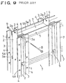
- reference numeral 1 designates a first or vertical support member formed from a metal material, such as aluminum or steel member, into an elongated form.
- the vertical support member 1 includes a top plate 2, for example, of a planer configuration, a pair of side plates 3, 3 extending from the opposite side edges of the top plate in the same direction, and a pair of flange portions 4, 4 extending from the side edge of the respective side plate in a direction perpendicular thereto.
- the side plates 3, 3, together with the top plate 2 form a substantially U-shaped configuration.
- the top plate 2 is formed with a plurality of holes 2a spaced apart from one another at a predetermined distance.
- Each of the side plates 3, 3 adjacent to the top plate 2 is formed with a plurality of slits 3a for receiving therein a second or horizontal support member which will be explained later.
- the slits 3a are spaced apart from one another at a distance the same as that of the holes 2a.
- Each of the flange portions 4, 4 is formed with a plurality of holes 4a for attachment thereof to a third support member which will be explained later.
- the slit 3a which is disposed at one end of the side plate, is formed so as to have an open end, it may be formed into a configuration substantially the same as that of the slits 3a disposed in the central portion of the side plate.
- the vertical support members 1 are so disposed that the top plates 2 of each pair of the support members 1 are oppositely disposed, and so that the pairs of the support members 1 are spaced apart from one another at a predetermined distance.
- a horizontal support member 5 is inserted in each slit 3a of the vertical support member 1, so as to form a grid-like configuration.
- the horizontal support member 5 is formed, for example, from a metal material, such as aluminum or steel, into an elongated web-like configuration. Holes 6 are also provided which correspond to the holes 2a of the vertical support member 1 spaced at a predetermined distance.
- the vertical support member 1 is formed first by forming the holes 2a, 4a, and slits 3a, for example, in a sheet metal by stamping operation, and then, bending the sheet metal in a predetermined direction, for example, by rolling or press operation, so as to obtain the configuration shown in Fig. 14.
- Reference numeral 7 designates block members.
- the block member may include a glass block, a glass brick, a glass panel and so on.
- the material for the block member may include, other than glass, resin material, for example.
- the block member 7 is supported by the vertical support members 1 and the horizontal support members 5 which are arranged in a grid-like configuration, as mentioned above. More specifically, the front and rear surfaces of the block member 7 are supported, at the opposite ends thereof, by the flange portions 4, 4 of the vertical support members 1, and the opposite side surfaces of the block member 7 are supported by the side plates 3, 3 of the vertical support members 1.
- the top surface and bottom surface of the block member 7 are supported by the upper edges 5a and lower edges 5b of the horizontal support members 5.
- the attachment means 8 such as a bolt
- Horizontal support members 5, 5 are inserted in the respective lowermost slits 3a of the vertical support members 1.
- a bolt 8 is inserted through a hole 6 of the horizontal support member 5 in the forward row, the hole 2a of the vertical support member 1, the hole 2a of the vertical support member 1 in the rearward row, and the hole 6 of the horizontal support member 5.
- the bolt is then threadingly engaged with a nut 9 for temporary securement thereof.
- the block member 7 in this state is inserted between the vertical support members 1, 1 from the above until the lower surface of the block member 7 is rested on the upper edge 5a of the horizontal support members 5, 5.
- An additional block member 7 is disposed adjacent to the first block member 7 in the above manner.
- a further additional block member 7 is disposed adjacent to the above additional block member 7, whereby the block member in a first stage (a first horizontal row) are all disposed in a proper manner.
- a horizontal support member 5 is inserted into a slit 3a next to the lowermost slit 3a in the vertical support member 1.
- a bolt 8 is inserted in each hole 2a in the vertical support member 1. Each bolt 8 is temporarily and lightly tightened by means of a nut 9.
- block members 7 in a second horizontal row are inserted between the pair of vertical support members 1, 1 from the above, so that their lower surfaces are mounted on the upper edges 5a of the pair of horizontal support members 5, 5.
- the above-mentioned operation is repeated in a similar manner.
- a new block member 7 is disposed adjacent to the first block member 7 in the second horizontal row.
- a further additional block member 7 is disposed adjacent to the new block member 7.
- all block members 7 in the horizontal second row are properly arranged.
- a horizontal support member 5 is inserted into the third slit 3a from the lowermost one.
- a bolt 8 is inserted into a respective holes 2a and 6 of the vertical support members 1.
- Each bolt 8 is temporarily and lightly tightened by means of a corresponding nut 9.
- an appropriate arrangement and adjustment operation is performed so that the opposite end portions of the front and rear surfaces of the block member 7 are engaged with the flange portions 4, 4 of the vertical support member 1, while the opposite side surfaces of the block member 7 are engaged with the side plates 3, 3 of the vertical support member 1.
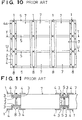
- the vertical support members 1 and the horizontal support members 5 in the forward and rearward row are tightened together by means of pairs of bolt 8 and nut 9 next to the lowermost stage. Similar operation will be repeated, so as to obtain a panel shown in Fig. 10.
- the vertical support members 1 having slits 3a in their side plates 3, 3, and the horizontal support members 5 are formed into a grid-like configuration, by inserting the horizontal support members 5 into the slits 3a in the vertical support members 1.
- the block members 7 of a rectangular configuration are disposed in their respective grid-like portions.
- the opposite end portions of the front and rear surfaces and the opposite end surfaces of the block members 7 are supported by the flange portions 4, 4 of the pair of vertical support members 1 and the side plates 3, 3.
- the lower and upper surfaces of the block members 7 are supported by the horizontal support members 5.
- the panel may be easily assembled, regardless of a given profile of the block member 7. It is also noted that adhesion such as joint cement is unnecessary, and contamination of an architectural construction and its periphery may be prevented.
- the vertical support members 1 and horizontal support members 5 are integrally tightened, at their overlapped portions, by means of the attachment means 8, 9.
- supporting ability for the block members 7 and mechanical strength of the panel are improved and increased, respectively. Accordingly, dislodgment of the block members 7 from the vertical support members 1 or the horizontal support members 5 due to vibrations or mechanical shock may be prevented.
- the block members 7 are supported by the vertical support members 1 and the horizontal support members 5 which are arranged in a grid-like configuration.
- panel size may be desirably changed by the size of the block member, when an appropriate length is selected for the vertical support members 1 and/or the horizontal support members 5. Accordingly, applicable field may be expanded, flexibility during fabrication may be enhanced, and reduction in fabrication period may be achieved.
- the panel structure advantageously provides design effects.
- the panel structures have various applications, other than partitions or screens for an architectural construction. Demand for the panel structure is increased, and, thus, easy applicability and cost reduction are highly required.
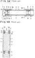
- the block members 7 are supported by the vertical support members 1 and the horizontal support members 5 of a web-like configuration which are combined into a grid-like configuration. It is noted, however, that the block members 7 are actually clamped and supported, at their front and rear surface on right-hand side and left-hand side, by the flange portions 4 of the vertical support members 1. Thus, the flange portions 4 are exposed only at the right-hand side and the left-hand side on the front and rear surface of the block members 7. This is disadvantageous in terms of providing good appearance.
- the vertical support member 1 includes slits 3a and formed into a substantially C-shaped configuration.
- its shape or configuration is different from that of the horizontal support member 5 which is of a web-like configuration.
- This inevitably increases the type of the support members and requires cumbersome production process. Reduction in manufacturing cost is also difficult. It is specifically noted that, as the panel structure increases in size, more complicated process for fabricating the vertical support members is required, thus increasing manufacturing cost.
- the block members 7 are supported in a following manner. First, the vertical support members 1 and the horizontal support members 5 of a web-like configuration are combined into a grid-like configuration by inserting each horizontal support member 5 into a slit 3a of a corresponding vertical support member 1. Then, block members 7 are mounted on the horizontal support members 5. Consequently, each block member 7 is clamped, at its left-hand and right-hand sides on front and rear surfaces, by the flange portions 4 of the vertical support members 1.
- such panel structure may be efficiently fabricated or constructed at site as compared to conventional one. It is noted, however, that further improvement is required for such panel structure, since more efficient and readily applicable panel structure is desired.
- a first invention provides a block member comprising a block body of a rectangular configuration having a center point and four sides, the block body including a flange portion in the outer peripheral surface of each of the four sides, the flange portions being formed integrally with the block body and protruding outwardly from the outer peripheral surface, each of the flange portions having a deformed portion which restricts the amount of protrusion of the flange portion, the deformed portions being formed in the flange portions in a symmetric relationship with respect to the center point of the block body.
- a second invention provides a block member comprising a block body of a rectangular configuration having a center point and four sides, the block body including a flange portion in the outer peripheral surface of each of the four sides, the flange portions being formed integrally with the block body and protruding outwardly from the outer peripheral surface, the flange portions having a thickness less than that of the outer peripheral surface, each of the flange portions having a deformed portion which restricts the amount of protrusion of the flange portion, the deformed portions being formed in the flange portions disposed at corner portions of the block body at which the adjoining sides of the block body meet together.
- a third invention provides a block body wherein the deformed portions are substantially of an arcuate configuration.
- a fourth invention provides a block member comprising a block body of a rectangular configuration having a center point and four sides, the block body including a flange portion in the outer peripheral surface of each of the four sides, the flange portions being formed integrally with the block body and protruding outwardly from the outer peripheral surface, the flange portions having a thickness less than that of the outer peripheral surface, each of the flange portions having a deformed portion which restricts the amount of protrusion of the flange portion, the deformed portion being formed in the central portion of each of the flange portions.
- a fifth invention provides a block member wherein the deformed portions are notches substantially of a semi-circular configuration or a C-shaped configuration.
- a sixth invention provides a panel structure comprising: block members each including a block body of a rectangular configuration having a center point and four sides, the block body including a flange portion in the outer peripheral surface of each of the four sides, the flange portions being formed integrally with the block body and protruding outwardly from the outer peripheral surface, each of the flange portions having a deformed portion which restricts the amount of protrusion of the flange portion, the deformed portions being formed in the flange portions in a symmetric relationship with respect to the center point of the block body; a pair of support members disposed along the front and rear surface, respectively, of the flange portion on each sides of the block member, each of the support members having at least one hole, the position of which corresponding to a position of a space defined by the deformed portions of the adjoining block members; and an attachment means including pairs of bolt and nut, wherein the pair of support members are disposed along the front and rear surfaces of the flange portion on each side of the block member, wherein the
- a seventh invention provides a panel structure comprising block members each comprising a block body of a rectangular configuration having a center point and four sides, the block body including a flange portion in the outer peripheral surface of each of the four sides, the flange portions being formed integrally with the block body and protruding outwardly from the outer peripheral surface, the flange portions having a thickness less than that of the outer peripheral surface, each of the flange portions having a deformed portion which restricts the amount of protrusion of the flange portion, the deformed portions being formed in the flange portions disposed at corner portions of the block body at which the adjoining sides of the block body meet together; a pair of support members disposed along the front and rear surface, respectively, of the flange portion on each sides of the block member, each of the support members having at least one hole, the position of which corresponding to a position of a space defined by the deformed portions of the adjoining block members; and an attachment means including pairs of bolt and nut, wherein the pair of support members are disposed
- a eighth invention provides a panel structure wherein the confronting flange portions of the adjoining block members are clamped by a common pair of support members.
- a ninth invention provides a panel structure wherein the support members are of a web-like configuration, and wherein each support member is formed with at least one attachment hole, the position of which corresponding to a space defined by the deformed portions of the block members.
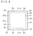
- reference numeral 20 designates a block member of a rectangular configuration.
- the block member may include, for example, a glass block, a glass brick, a glass panel or the like.
- a brick, a ceramic, a resin material, or a wooden material, in addition to the glass material, may be used as a raw material for the block member.
- the block member 20 shown in the drawings is formed into a square configuration when viewed in plan view (front view). It is noted, however, that the block member may be formed into an appropriate configuration such as a rectangular, rhombic, triangular, or regular polygonal configuration.
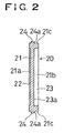
- the block member 20 includes a block body 21 for example of a rectangular configuration, a first shallow recess 22 formed in one surface (front surface) 21a of the block body 21, a second deep recess 23 formed in the opposite surface (rear surface) 21b of the block body 21, and a flange portion 24 integrally protruding from the outer peripheral surface 21c of each of the four sides of the block body 21, the width of the flange portion 24 being less than that of the outer peripheral surface 21c.
- the flange 24 has a deformed portion 25 of an arcuate configuration (removed portion) at each corner portion in which the adjoining sides of the block body 21 intersect with each other.
- the amount of protrusion (protruded length) of the flange portion from the outer peripheral surface 21c is restricted. More specifically, the protruded length of the flange portion is reduced as the flange portion approaches the corner portion.
- the adjoining deformed portions 25 form a space 26, when a plurality of block members 20 are arranged in a matrix form so as to be panelized. It is noted that , although the opposite surface 24a of the flange portion 24 is shown to be in flush with the bottom surface 23a of the recess 23, it may be formed to be offset from the bottom surface 23a.
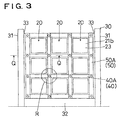
- reference numeral 30 designates a support frame body.
- the support frame body 30 includes, for example, support columns 31, 31 spaced apart a predetermined distance from one another, a base member 32 disposed below and fixed to the support columns 31, 31, and end support members 33, 33 disposed upper and fixed to the confronting support columns 31, 31.
- the end support members 33, 33 have, at their confronting central portion, a support lug 33a integral therewith.
- Each of the support lug 33a extends along the entire length of the central portion and has a thickness substantially the same as that of the flange portion of the block member 20, and a protruded length approximately twice that of the flange portion 24.
- Attachment holes are arranged at a pitch substantially the same as the outer dimension of the block member 20.
- a plurality of block members 20 are arranged in a matrix form, with the flange portions 24 being in abutment relative to one another.
- a caulking compound such as silicone rubber, may be interposed between the opposed surfaces of the flange portions 24, so as to prevent direct contact between the flange portions.
- a space is formed which is bounded by the arcuate deformed portions 25.
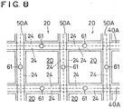
- the flange portion 24 on each side of the block member 20 is clamped by support members 40, 40A and vertical support members 50, 50A of a web-like configuration, which are respectively arranged forwardly and rearwardly of the block members and extend horizontally and vertically.
- the flange portions are tightly clamped by means of an attachment means such as a bolt 60 and a nut (for example, a box nut) 61.
- the horizontal support members 40, 40A, and the vertical support members 50, 50A are formed with a plurality of attachment holes 41, 51, respectively.
- the attachment holes 41, 51 are arranged at a pitch substantially the same as that of the outer dimension of the block member 20 (outer dimension including the flange portion 24).
- the vertical support members 50, 50A disposed adjacent to the support frame body 30 have a width slightly larger than that of the remaining vertical support members 50, 50A.
- the horizontal support members 40, 40A and the vertical support members 50, 50A, which are not disposed adjacent to the support frame body 30, have a width substantially equal to or slightly larger than twice the protruded length of each side of the block member 20 in which the deformed portion is not formed.
- Each block member 20 is securely supported by inserting a bolt 60 into each hole 41, 51 in the horizontal support members 40, 40A and the vertical support members 50, 50A, respectively, and through each space 26 and by tightly threading the bolts 60 with corresponding box nuts 61.
- the horizontal support members 40, 40A and the vertical support members 50, 50A are temporarily and lightly secured to the base member 32 and the end support members 33, 33 along their front and rear surfaces by means of bolts 60 and box nuts 61 through the use of the holes 41, 51.
- a plurality of vertical support members 50, 50A for the front and rear surfaces of the panel structure are disposed between the vertical support members 50, 50A extending along the end support members 33, 33, respectively.
- the vertical support members are arranged substantially in parallel relative to one another.
- the vertical support members 50, 50A are temporarily and lightly secured to the horizontal support members 40, 40A extending along the base member 33 by means of the bolts 60 and the box nuts 61. If desired, an appropriate amount of caulking compound is applied to the end surface of the flange portion 24 at each side of the block members20. Then, such block members 20 are sequentially disposed between the horizontal support members 40, 40A on the base member 32, in a manner that the lower flange portion 24 of each of the block members 20 are clamped between the horizontal support members 40, 40A. In this manner, arrangement for the first row is completed.
- each of the block members 20 are engaged by or disposed adjacent to the horizontal support members 40, 40A and the vertical support members 50, 50A.
- application of the caulking compound to the base member 32, the opposite end surfaces of the support lugs 33a, 33a, and the block members 20 may be performed when the arrangement of the block members 20 in the first row has been completed.
- a bolt 60 is inserted in each hole in the horizontal support members 40, 40A, as well as in each lowermost hole (a first hole) in the vertical support members 50, 50A.
- Each bolt 60 is tightly threaded with a corresponding box nut 61.
- a second pair of horizontal support members 40, 40A are disposed along the front and rear surfaces of the upper flange 24 of each of the block members 20 in the first row.
- a bolt 60 is inserted into a hole 51 next to the lowermost hole (a second hole) of each of the vertical support members 50, 50A, a hole 41 in each of the second pair of horizontal support 40, 40A, which corresponds to the second hole 51, and each space 26 defined by the deformed portions 25, 25 on each upper side of the adjoining block members 20.
- Each bolt 60 is temporarily and lightly tightened by a corresponding box nut 61.
- a second row of block members 20 are disposed on the first row of block members 20, with their flange portions 24 being engaged or disposed adjacent to one another.
- the block member 20 applied to the panel structure has, in its peripheral surface 21 on each side thereof, the integral flange portion 24 provided with the deformed portion 25.
- the adjoining flange portions 24 of the block members may be simultaneously clamped by means of the horizontal support members 40, 40A and the vertical support members 50, 50A.
- the block member 20 is formed, at each corner portion thereof, with the arcuately deformed portion 25.
- the deformed portions 25 contribute to restrict the amount of protrusion of the flange portions 24.
- Such deformed portions 25 cooperate to define a space 26 when block members 20 are adjacently disposed.
- the adjoining flange portions 24 of the block members 20 are securely and commonly clamped by inserting a bolt 60 in each space 26 and by tightening the bolt 60 with a corresponding box nut 60.
- moldability of the block members 20 may be advantageously improved due to the provision of the deformed portions 25.
- the spaces 26 obviate provision of any attachment means in the flange portions.
- the block members 20 may be sufficiently securely clamped, even when the protruded length of the flange portions 24 from their outer peripheral surfaces 21c is reduced, for example, to about 5 mm.
- the horizontal support members 40, 40A and the vertical support members 50, 50A are formed into a web-like configuration. Thus, they may be produced simply by cutting a flat material into a predetermined length and by forming holes at a predetermined pitch. This allows easy manufacturing operation, greatly increased production rate, and reduction in production cost of the support members, as well as reduction in production cost of the panel structure.
- the horizontal and vertical support members are of a web-like configuration as mentioned above, it is unnecessary for the second support of a web-like configuration to be inserted into a slit in the first support of a C-shaped configuration as needed upon assembly of the above-mentioned earlier proposal of the applicant. That is to say, the horizontal and vertical support members according to the invention may be assembled by simply overlapping them relative to one another. Accordingly, the panel structure may be efficiently fabricated or assembled in a short time.
- a quantity of caulking compound such as silicone rubber may be applied to the portions, to be engaged or adjacently disposed, of the flange portions 24 of adjoining block members 20.
- the caulking compound may serve as a cushioning material between the block members 20, so as to prevent the block members 20 from damage due to strong vibrations or shock.
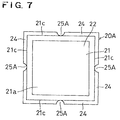
- Fig. 7 shows a block member according to another embodiment of the invention.
- the block member 20A includes, in the outer peripheral surface 21c on each side of the block body 21 of a rectangular configuration, flange portions 24 integral therewith.
- Each flange portion 24 has a thickness less than that of the outer peripheral surface 21c.
- the flange portion 24 on each side of the block body 21 is formed, at the central portion thereof, with a deformed portion 25A of a semi-circular configuration which restricts the amount of protrusion of the flange 24 from the outer peripheral surface 21c.
- the deformed portion 25A may be formed, in stead of the semi-circular configuration, into a C-shaped configuration, a triangular configuration or the like.
- the block member 20A may be applied for example to a panel structure shown in Fig. 8.
- This panel structure is basically the same as that shown in Figs. 3 to 5 but different in that (1) the position of each hole 41, 51 of the horizontal and vertical support members 40, 40A and 50, 50A is shifted to the central portion of the block member 20A and (2) the deformed portions 25 of the adjoining block members 20A define a space in the central portion of the flange portions 24.
- the flange portions 24 of the block members 20A are separately clamped by the horizontal support members 40, 40A and the vertical support members 50, 50A, respectively.
- the panel structure employing the support members according to this embodiment is slightly less in strength than that of the panel structure employing the support members according to the first embodiment in which the overlapped portions between the horizontal support members 40, 40A and the vertical support members 50, 50A are simultaneously fastened together by means of the fastening means 60, 61.
- the panel structure employing the support members according to the second embodiment is expected to have substantially the same effects as those of the panel structure employing the support members according to the first embodiment.
- the block member may take a form of rectangular, triangular or polygonal configuration, other than the above-mentioned square configuration. More than one deformed portions may be formed in a single side of the flange portion, provided that symmetrical relationship may be obtained with respect to the adjacently disposed block members The location(s) of the deformed portion may also be appropriately selected. It is also possible to use an L-shaped auxiliary fixture. In this case, one piece of the fixture is fastened to the attachment means located at lowermost stage of the panel structure, while the other piece of the fixture is fixed to the base member by means of a screw.
- One support member (horizontal or vertical support member) overlying the other support member (vertical or horizontal support member), except the portion at which it is disposed on the underlying support member, may be bent by an amount substantially corresponding to the thickness of the underlying support member.
- the overlying support member may be intimately contacted with the flange portion of the block member.
- each block member is integrally formed, in the outer peripheral surface of each side thereof, with a flange portion.
- adjoining flange portions may be clamped together by means of a pair of support members. This increases support strength for the block members.
- Deformed portions which restrict amount of protrusion of the flange portion, are formed in the outer peripheral portions of the block members in a symmetrical relationship.
- a space is formed by the deformed portions. This space may be used when tightening operation is performed using an attachment means. It is also possible to reduce the protruded length of the flange from the peripheral surface. This permits reduction in width of the support members. Accordingly, and contrariwise to prior art, the support member is prevented from overlapping the block member. The area by which the support members occupy in the panel structure may be decreased. This provides superior appearance of the panel structure.
- horizontal and vertical support members are both of a web-like configuration. Thus, they may be easily produced simply by cutting a flat material into a predetermined width. The length of the support members may be appropriately adjusted. Thus, the support members may be produced easily. Mass productivity is also significantly increased. Accordingly, it is possible to reduce production cost for support members and panel structure.
- the horizontal and vertical support members of a web-like configuration obviate the cumbersome operation in prior art in which a second or horizontal support member is inserted into a slit of a first or vertical support member of a C-shaped configuration.
- the support members according to the invention may be simply overlapped with each during assembling or fabricating process. This permits efficient fabrication work in a short period of time.
Landscapes
- Engineering & Computer Science (AREA)
- Architecture (AREA)
- Civil Engineering (AREA)
- Structural Engineering (AREA)
- Physics & Mathematics (AREA)
- Electromagnetism (AREA)
- Panels For Use In Building Construction (AREA)
- Finishing Walls (AREA)
- Furniture Connections (AREA)
Abstract
Description
Claims (9)
- A block member comprising a block body of a rectangular configuration having a center point and four sides, the block body including a flange portion in the outer peripheral surface of each of the four sides, the flange portions being formed integrally with the block body and protruding outwardly from the outer peripheral surface, each of the flange portions having a deformed portion which restricts the amount of protrusion of the flange portion, the deformed portions being formed in the flange portions in a symmetric relationship with respect to the center point of the block body.
- A block member comprising a block body of a rectangular configuration having a center point and four sides, the block body including a flange portion in the outer peripheral surface of each of the four sides, the flange portions being formed integrally with the block body and protruding outwardly from the outer peripheral surface, the flange portions having a thickness less than that of the outer peripheral surface, each of the flange portions having a deformed portion which restricts the amount of protrusion of the flange portion, the deformed portions being formed in the flange portions disposed at corner portions of the block body at which the adjoining sides of the block body meet together.
- A block body according to Claim 2, wherein the deformed portions are substantially of an arcuate configuration.
- A block member comprising a block body of a rectangular configuration having a center point and four sides, the block body including a flange portion in the outer peripheral surface of each of the four sides, the flange portions being formed integrally with the block body and protruding outwardly from the outer peripheral surface, the flange portions having a thickness less than that of the outer peripheral surface, each of the flange portions having a deformed portion which restricts the amount of protrusion of the flange portion, the deformed portion being formed in the central portion of each of the flange portions.
- A block member according to Claim 4, wherein the deformed portions are notches substantially of a semi-circular configuration or a C-shaped configuration.
- A panel structure comprising: block members each including a block body of a rectangular configuration having a center point and four sides, the block body including a flange portion in the outer peripheral surface of each of the four sides, the flange portions being formed integrally with the block body and protruding outwardly from the outer peripheral surface, each of the flange portions having a deformed portion which restricts the amount of protrusion of the flange portion, the deformed portions being formed in the flange portions in a symmetric relationship with respect to the center point of the block body; a pair of support members disposed along the front and rear surface, respectively, of the flange portion on each sides of the block member, each of the support members having at least one hole, the position of which corresponding to a position of a space defined by the deformed portions of the adjoining block members; and an attachment means including pairs of bolt and nut, wherein the pair of support members are disposed along the front and rear surfaces of the flange portion on each side of the block member, wherein the pair of support members are tightened together by means of the attachment means, through the use of the holes of the support members and the space defined by the deformed portions of the block members, whereby the flange portions of the block members are clamped by the support members.
- A panel structure comprising block members each comprising a block body of a rectangular configuration having a center point and four sides, the block body including a flange portion in the outer peripheral surface of each of the four sides, the flange portions being formed integrally with the block body and protruding outwardly from the outer peripheral surface, the flange portions having a thickness less than that of the outer peripheral surface, each of the flange portions having a deformed portion which restricts the amount of protrusion of the flange portion, the deformed portions being formed in the flange portions disposed at corner portions of the block body at which the adjoining sides of the block body meet together; a pair of support members disposed along the front and rear surface, respectively, of the flange portion on each sides of the block member, each of the support members having at least one hole, the position of which corresponding to a position of a space defined by the deformed portions of the adjoining block members; and an attachment means including pairs of bolt and nut, wherein the pair of support members are disposed along the front and rear surfaces of the flange portion on each side of the block member, wherein the pair of support members are tightened together by means of the attachment means, through the use of the holes of the support members and the space defined by the deformed portions of the block members, whereby the flange portions of the block members are clamped by the support members.
- A panel structure according to Claim 6 or 7 wherein the confronting flange portions of the adjoining block members are clamped by a common pair of support members.
- A panel structure according to any one of Claims 6 to 8 wherein the support members are of a web-like configuration, and wherein each support member is formed with at least one attachment hole, the position of which corresponding to a space defined by the deformed portions of the block members.
Applications Claiming Priority (3)
| Application Number | Priority Date | Filing Date | Title |
|---|---|---|---|
| JP24617196 | 1996-09-18 | ||
| JP24617196 | 1996-09-18 | ||
| JP246171/96 | 1996-09-18 |
Publications (3)
| Publication Number | Publication Date |
|---|---|
| EP0831184A2 true EP0831184A2 (en) | 1998-03-25 |
| EP0831184A3 EP0831184A3 (en) | 1998-12-02 |
| EP0831184B1 EP0831184B1 (en) | 2002-09-04 |
Family
ID=17144577
Family Applications (1)
| Application Number | Title | Priority Date | Filing Date |
|---|---|---|---|
| EP97301890A Expired - Lifetime EP0831184B1 (en) | 1996-09-18 | 1997-03-20 | Block member and panel structure |
Country Status (4)
| Country | Link |
|---|---|
| US (1) | US5860260A (en) |
| EP (1) | EP0831184B1 (en) |
| KR (1) | KR100436411B1 (en) |
| DE (1) | DE69715118T2 (en) |
Families Citing this family (8)
| Publication number | Priority date | Publication date | Assignee | Title |
|---|---|---|---|---|
| US6751915B2 (en) | 1997-01-09 | 2004-06-22 | New England Classic Interiors, Inc. | Kits and systems releasably attachable to a wall, and methods employing same |
| US6374562B1 (en) * | 2000-06-28 | 2002-04-23 | New England Classic Interiors, Inc. | Adjustably sizeable raised panel system for stairs and method for forming and installing same |
| US6427399B1 (en) * | 1998-10-26 | 2002-08-06 | Hy-Lite Products, Inc. | Block window system with border frame |
| US6892498B1 (en) | 2001-12-05 | 2005-05-17 | James D. Roman | Interlocking construction system |
| US7185469B2 (en) * | 2003-03-14 | 2007-03-06 | Advantage Architectural Products, Ltd. | Modular raised wall paneling system |
| US20070033881A1 (en) * | 2005-08-15 | 2007-02-15 | Love Bethel W | Safety and security block window system |
| US9349153B2 (en) * | 2007-04-25 | 2016-05-24 | Digimarc Corporation | Correcting image capture distortion |
| CH711479B1 (en) * | 2015-08-31 | 2018-08-15 | Marco Semadeni Dr | Component with hollow glass blocks. |
Citations (2)
| Publication number | Priority date | Publication date | Assignee | Title |
|---|---|---|---|---|
| FR654424A (en) * | 1927-06-13 | 1929-04-05 | Glass plate for floors, walls and ceilings | |
| DE3136542A1 (en) * | 1981-09-15 | 1983-03-31 | Westerwald Aktiengesellschaft für Silikatindustrie, 5432 Wirges | Glass-block wall |
Family Cites Families (16)
| Publication number | Priority date | Publication date | Assignee | Title |
|---|---|---|---|---|
| US2182373A (en) * | 1938-08-10 | 1939-12-05 | Pittsburgh Plate Glass Co | Frangible block mounting |
| US2198450A (en) * | 1939-08-30 | 1940-04-23 | Jack O Chertkof | Light transmitting structure |
| US3205633A (en) * | 1963-01-03 | 1965-09-14 | Nusbaum Mortimer | Floor or like tile |
| FR2542353B1 (en) * | 1983-03-09 | 1985-10-25 | Manon Gerard | GLASS ELEMENT, PARTICULARLY BRICK OR GLASS PAVE |
| JPS6153958A (en) * | 1984-08-20 | 1986-03-18 | 株式会社 サアミ | Laying of tile like fiber floor material |
| DK155616C (en) * | 1984-09-25 | 1989-09-04 | Eminent Plast | GRID OR MEASUREMENT ELEMENT FOR THE CREATION OF A FLOOR COVERING BY CONNECTION WITH SIMILAR ELEMENTS |
| EP0215994B1 (en) * | 1985-09-26 | 1989-02-22 | Rolf Scheiwiller | Set of elements for composite constructions |
| US5003744A (en) * | 1989-07-31 | 1991-04-02 | Innovative Building Products, Inc. | Glass-block panels with improved thermal conduction characteristics |
| JPH03140536A (en) * | 1989-10-26 | 1991-06-14 | Nikken Sekkei Ltd | Glass block wall and assembling method thereof |
| JP3031558B2 (en) * | 1990-05-14 | 2000-04-10 | 順成 江本 | Manufacturing method of wall-like structures |
| JPH0468115U (en) * | 1990-10-26 | 1992-06-17 | ||
| US5259161A (en) * | 1991-06-03 | 1993-11-09 | Carter Frank P | Vertical and horizontal reinforcement and spacing guide for panels constructed of blocks |
| US5170604A (en) * | 1991-08-21 | 1992-12-15 | Tamer Industries, Inc. | Wall panel system and fastener therefor |
| JPH0547140U (en) * | 1991-11-29 | 1993-06-22 | タキロン株式会社 | Translucent block |
| JPH068545U (en) * | 1992-06-29 | 1994-02-04 | タキロン株式会社 | Translucent block |
| US5448864A (en) * | 1993-06-22 | 1995-09-12 | Rosamond; John E. | Multi-light glass block panel assembly and method |
-
1997
- 1997-03-20 EP EP97301890A patent/EP0831184B1/en not_active Expired - Lifetime
- 1997-03-20 DE DE69715118T patent/DE69715118T2/en not_active Expired - Fee Related
- 1997-03-24 US US08/822,003 patent/US5860260A/en not_active Expired - Fee Related
- 1997-04-02 KR KR1019970012095A patent/KR100436411B1/en not_active IP Right Cessation
Patent Citations (2)
| Publication number | Priority date | Publication date | Assignee | Title |
|---|---|---|---|---|
| FR654424A (en) * | 1927-06-13 | 1929-04-05 | Glass plate for floors, walls and ceilings | |
| DE3136542A1 (en) * | 1981-09-15 | 1983-03-31 | Westerwald Aktiengesellschaft für Silikatindustrie, 5432 Wirges | Glass-block wall |
Also Published As
| Publication number | Publication date |
|---|---|
| DE69715118T2 (en) | 2003-04-24 |
| US5860260A (en) | 1999-01-19 |
| EP0831184A3 (en) | 1998-12-02 |
| EP0831184B1 (en) | 2002-09-04 |
| KR19980023988A (en) | 1998-07-06 |
| KR100436411B1 (en) | 2004-10-02 |
| DE69715118D1 (en) | 2002-10-10 |
Similar Documents
| Publication | Publication Date | Title |
|---|---|---|
| US5606840A (en) | Panel and panel structure | |
| EP0982450B1 (en) | Ready-mixed concrete placing method and formwork unit used for the method | |
| US5860260A (en) | Block member and panel structure | |
| WO2006075841A1 (en) | Length adjustable passenger handle assembly for elevator | |
| US3075621A (en) | Wall panel and process of assembling same | |
| KR20010013486A (en) | Structure for mounting panel to building skeleton wall surface | |
| JP2775014B2 (en) | Construction method of composite wall | |
| JP2509845Y2 (en) | Wall panel | |
| JP3043300B2 (en) | Block members and panel structures | |
| KR101973661B1 (en) | gabion retaining wall block with built-up type | |
| JPH0791886B2 (en) | Lighting enclosure | |
| JPH0728261Y2 (en) | Exterior panel mounting structure | |
| JPH0350207Y2 (en) | ||
| JPH11247336A (en) | Exterior facing panel and jig for mounting the same | |
| JPH0752855Y2 (en) | Exterior wall decoration panel mounting device | |
| JPH0355691Y2 (en) | ||
| JPH0348368Y2 (en) | ||
| AU2022228128A1 (en) | Wall arrangement | |
| JPH0481018B2 (en) | ||
| JPH0728387Y2 (en) | Arched window frame | |
| JPS6246745Y2 (en) | ||
| JPS5931613B2 (en) | Exterior wall mounting method and mounting hardware | |
| JPH0334416Y2 (en) | ||
| JP2517921Y2 (en) | Connection tool and support stand | |
| JPH04216745A (en) | Glass block and its structure |
Legal Events
| Date | Code | Title | Description |
|---|---|---|---|
| PUAI | Public reference made under article 153(3) epc to a published international application that has entered the european phase |
Free format text: ORIGINAL CODE: 0009012 |
|
| AK | Designated contracting states |
Kind code of ref document: A2 Designated state(s): DE FR GB IT NL |
|
| AX | Request for extension of the european patent |
Free format text: AL;LT;LV;RO;SI |
|
| 17P | Request for examination filed |
Effective date: 19980223 |
|
| PUAL | Search report despatched |
Free format text: ORIGINAL CODE: 0009013 |
|
| AK | Designated contracting states |
Kind code of ref document: A3 Designated state(s): DE FR GB IT NL |
|
| AX | Request for extension of the european patent |
Free format text: AL;LT;LV;RO;SI |
|
| AKX | Designation fees paid |
Free format text: DE FR GB IT NL |
|
| 17Q | First examination report despatched |
Effective date: 20010320 |
|
| GRAG | Despatch of communication of intention to grant |
Free format text: ORIGINAL CODE: EPIDOS AGRA |
|
| GRAG | Despatch of communication of intention to grant |
Free format text: ORIGINAL CODE: EPIDOS AGRA |
|
| GRAH | Despatch of communication of intention to grant a patent |
Free format text: ORIGINAL CODE: EPIDOS IGRA |
|
| GRAH | Despatch of communication of intention to grant a patent |
Free format text: ORIGINAL CODE: EPIDOS IGRA |
|
| GRAA | (expected) grant |
Free format text: ORIGINAL CODE: 0009210 |
|
| AK | Designated contracting states |
Kind code of ref document: B1 Designated state(s): DE FR GB IT NL |
|
| PG25 | Lapsed in a contracting state [announced via postgrant information from national office to epo] |
Ref country code: NL Free format text: LAPSE BECAUSE OF FAILURE TO SUBMIT A TRANSLATION OF THE DESCRIPTION OR TO PAY THE FEE WITHIN THE PRESCRIBED TIME-LIMIT Effective date: 20020904 |
|
| REG | Reference to a national code |
Ref country code: GB Ref legal event code: FG4D |
|
| REF | Corresponds to: |
Ref document number: 69715118 Country of ref document: DE Date of ref document: 20021010 |
|
| NLV1 | Nl: lapsed or annulled due to failure to fulfill the requirements of art. 29p and 29m of the patents act | ||
| ET | Fr: translation filed | ||
| PLBE | No opposition filed within time limit |
Free format text: ORIGINAL CODE: 0009261 |
|
| STAA | Information on the status of an ep patent application or granted ep patent |
Free format text: STATUS: NO OPPOSITION FILED WITHIN TIME LIMIT |
|
| 26N | No opposition filed |
Effective date: 20030605 |
|
| PGFP | Annual fee paid to national office [announced via postgrant information from national office to epo] |
Ref country code: GB Payment date: 20080326 Year of fee payment: 12 |
|
| PGFP | Annual fee paid to national office [announced via postgrant information from national office to epo] |
Ref country code: FR Payment date: 20080311 Year of fee payment: 12 Ref country code: DE Payment date: 20080313 Year of fee payment: 12 |
|
| PGFP | Annual fee paid to national office [announced via postgrant information from national office to epo] |
Ref country code: IT Payment date: 20080328 Year of fee payment: 12 |
|
| GBPC | Gb: european patent ceased through non-payment of renewal fee |
Effective date: 20090320 |
|
| REG | Reference to a national code |
Ref country code: FR Ref legal event code: ST Effective date: 20091130 |
|
| PG25 | Lapsed in a contracting state [announced via postgrant information from national office to epo] |
Ref country code: DE Free format text: LAPSE BECAUSE OF NON-PAYMENT OF DUE FEES Effective date: 20091001 |
|
| PG25 | Lapsed in a contracting state [announced via postgrant information from national office to epo] |
Ref country code: GB Free format text: LAPSE BECAUSE OF NON-PAYMENT OF DUE FEES Effective date: 20090320 Ref country code: FR Free format text: LAPSE BECAUSE OF NON-PAYMENT OF DUE FEES Effective date: 20091123 |
|
| PG25 | Lapsed in a contracting state [announced via postgrant information from national office to epo] |
Ref country code: IT Free format text: LAPSE BECAUSE OF NON-PAYMENT OF DUE FEES Effective date: 20090320 |