EP0830630B1 - Stereoscopic display device - Google Patents
Stereoscopic display device Download PDFInfo
- Publication number
- EP0830630B1 EP0830630B1 EP96917574A EP96917574A EP0830630B1 EP 0830630 B1 EP0830630 B1 EP 0830630B1 EP 96917574 A EP96917574 A EP 96917574A EP 96917574 A EP96917574 A EP 96917574A EP 0830630 B1 EP0830630 B1 EP 0830630B1
- Authority
- EP
- European Patent Office
- Prior art keywords
- image
- images
- viewing
- display device
- viewable
- Prior art date
- Legal status (The legal status is an assumption and is not a legal conclusion. Google has not performed a legal analysis and makes no representation as to the accuracy of the status listed.)
- Expired - Lifetime
Links
Images


Classifications
-
- G—PHYSICS
- G02—OPTICS
- G02B—OPTICAL ELEMENTS, SYSTEMS OR APPARATUS
- G02B30/00—Optical systems or apparatus for producing three-dimensional [3D] effects, e.g. stereoscopic images
- G02B30/20—Optical systems or apparatus for producing three-dimensional [3D] effects, e.g. stereoscopic images by providing first and second parallax images to an observer's left and right eyes
- G02B30/26—Optical systems or apparatus for producing three-dimensional [3D] effects, e.g. stereoscopic images by providing first and second parallax images to an observer's left and right eyes of the autostereoscopic type
Definitions
- the present invention relates to a stereoscopic display device.
- stereoscopic displays are known, there is a growing class of displays which provide for the viewing of stereoscopic images without the use of special viewing aids, these are known as autostereoscopic displays. They are all characterised by the use of some view determining means whereby each of the viewer's two eyes see a different image on a screen.
- a stereoscopic image two 2D images are used (we will call them half images) taken together they are known as a stereo pair.
- the stereoscopic effect is produced by the difference in perspective of the two half images.
- Each half image is formed at a certain distance from the viewer and the viewer's eyes will focus on the image.
- the eye's accommodation is one of the many visual cues interpreted by the brain to give depth information.
- any difference in depth sensation provided by the stereoscopic effect will contradict the depth information provided by accommodation. In practice it is necessary to restrict this conflict, otherwise viewer discomfort and eyestrain will occur.
- Autostereoscopic displays generally form their half pictures on the plane of a viewing screen. The size of the screen is usually severely limited by a number of factors and to minimise the conflict between accommodation and stereoscopy the 3D image needs to be formed close to the display screen.
- the size of the 3D image is also determinable and clearly observable. (This may be contrasted with a 2D picture where no depth information is present so a large object will appear to be a large object even if the size of the image is small.)
- US-A-4535354 describes a system for projecting a pair of stereoscopic pictures which can be seen in three dimensions without the observer wearing special spectacles or using other optical aids.
- US-A-5379133 discloses a display device with a holographic integrated combiner screen and a projecting lens to generate multi-zone outputs, each zone of which may be presented for stereoscopic viewing at a discrete viewing station.
- a stereoscopic display device comprising:
- the present invention allows the formation of the viewable image(s) at an arbitrary distance from the viewer and of an arbitrary size which is not limited by the size of the display itself.
- a convenient analogy is a window: a very large scene can be seen through a small window. In the present invention, a large scene may be seen as if though the display window.
- This invention provides a means whereby three dimensional images may be seen without the use of glasses, head mounted displays or similar inconvenient viewing aids, it also provides for the viewing of images which may be substantially larger than the display itself.
- the image bearing means may be an LCD, or a screen (which may be a holographic optical element) onto which the viewable image is projected.
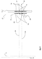
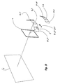
- Figure 1 shows a generalised arrangement of a display according to the invention.
- the display comprises an image bearing device 2 which generates a pair of superimposed real 2D half images (referred to hereinafter as 2l, 2r - not shown).
- the image bearing device 2 lies between the back focal point of a focusing optic 1 (with positive optical power) and the optic itself.
- the two half pictures 2l,2r are provided with view determining apertures 3,4 respectively by means not shown.
- the viewer is positioned such that the left and right eyes 8l,8r are located roughly as indicated.
- Images 6,7 of the view determining apertures 3,4 form real images as indicated, these images 6,7 determine respectively the zones whence the images 5l,5r of each half picture 2l,2r may be seen.
- Figure 1 we illustrate a simple case where viewing apertures 6,7 are conveniently located such that the left eye 81 observes the enlarged left half image 51 through aperture 6 and the right eye observes the enlarged right half image 5r through aperture 7.
- the size of the image 5 of stereo pair 2 can be substantially larger than the diameter of the optic 1, the stereoscopic image can be located in the general location of the virtual image 5 thereby achieving our goal of providing a relatively small autostereoscopic display which displays large 3D without introducing unacceptable depth cue conflicts between accommodation and stereopsis.
- Figure 1A shows the arrangement of Figure 1 with a number of example rays added.
- Figure 1B shows a number of construction lines used in the construction of the real and virtual images of Figure 1.
- the lines 40-43 with short dashes are rays used in the construction of the virtual image 5.
- the lines 44-47 with medium dashes are used in the construction of the real image viewing zones 6,7.
- Optic 1 can be a lens or lens combination. It can be a mirror or mirror combination, it can be a holographic/ diffractive optical element or combination of such elements. It may also be a combination of different types of element, e.g. lens and mirror.
- optic 1 will operate off-axis, it might also be advantageous for there to be some minor aberrations introduced by the optic 1 to blur the images of pixels and thereby to provide a more homogeneous picture.
- the stereo pair 2l,2r may be provided by projection onto a holographic screen.
- FIG. 2 which is a plan view and not to scale.
- the Holographic elements 9 reconstructs an even diffuse zone when illuminated by a correctly positioned light source
- the projector 10l may be considered a light source and will reconstruct the diffuse zone 3
- projector 10r acts in a similar way and reconstructs a diffuse zone 4
- the displacement between zones 3 and 4 is caused by the displacement between projectors 10l and 10r.
- Zones 3 and 4 can be reconstructed at infinity or as virtual images or as real images.
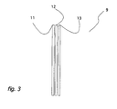
- the holographic element 9 can be a simple transmission hologram or a reflection hologram, it can also be advantageously constructed as illustrated in Figure 3 where it is composed of a diffraction grating 11, a louvred screen 12 and the holographic recording 13 of the diffuse zone, this configuration provides dispersion compensation.
- the aggregate optical power of the grating 11 and hologram 13 should be near zero and they are made so that the grating 11 and hologram 13 provide equal and opposite dispersion, with this particular configuration the optic 1 may be placed in contact with the hologram or hologram combination 9, either between it and the projectors 10 or on the other face between it and the viewing position.
- zones 3,4 would be advantageously inclined at the achromatic angle so as to facilitate good colour rendition.
- the stereo pair 2l,2r may be provided by a single transmissive image element and a single hologram.
- the stereoscopic pair 2 and zones 3,4 are generated by a combination of a light source, a hologram and a transmissive image bearing panel which can be a LCD and will be described as such in the following.
- LCD 14 is considered as being composed of two sets of pixels 15 and 16 (only two of each are shown in the figure). Pixels 15 display the left stereo half image between them and pixels 16 the right stereo half image.
- a hologram 17 is set next to the LCD (in the case shown it is behind, it can be in front).
- the hologram 17 is composed of two sets of elements 18,19 which may or may not overlap, it is illuminated by a beam of light 20. We have illustrated some rays of light for the purpose of explanation, clearly there are many more rays that could be drawn which are not necessarily parallel to the illustrated ones.
- Part of light 20 strikes hologram element 18 where it reconstructs the image 3 of a diffuse area of light, in the illustrated case this is a virtual image where diffracted ray 21 appears to originate from image 3. It will be noticed that diffracted ray 21 passes through a member of pixel set 15.
- the hologram and LCD are arranged such that the light diffracted by all the members of the set of hologram elements 18 pass through members of the pixel set 15 and not through any members of set 16.
- the light 21 is modulated by the image displayed by pixel set 15. The same occurs mutatis mutandis in the case of hologram element set 19, image 4, rays 22 and pixel set 16.
- the two virtual images 3,4 are of evenly illuminated diffuse zones of light, they are advantageously co-planar and abut each other side to side with neither overlap nor gap between them. (The figure is a vertical section and distorted slightly for clarity so this is not shown precisely.)
- the zones 3,4 are re-imaged as real images 6,7 forming the left and right viewing zones respectively.
- stereo pair 2l,2r may be formed by two separate LCDs and a beamsplitter.
- Stereo pair 2 can be the optical image of one or both of the stereo half images. There are a number of optical methods to overlap one image on another, we will describe a simple one which makes use of a beamsplitter.
- the left half image is displayed on transmissive display 25, it is illuminated in such a way that the light passing through it originates from or appears to originate from the diffuse zone 3.
- One way of achieving this is to use a holographic element to illuminate the half image 25, which is particularly advantageous if the optical design of the whole display means that the diffuse zone 3 should be at a great distance or if it should be a real, rather than virtual, image.
- Light 28 has passed through the half image and then passes through beamsplitter 27 on towards optic 1.
- the right half image is displayed and illuminated in the same way with the sole difference that the light 29 is reflected from the beamsplitter 27 such that the image of half image 26 is superimposed upon half image 25 and the zone 4 appears adjacent to zone 3. Once reflected, light 29 continues parallel to light 28 on towards the optic 1.
- the stereo pair 2 and zones 3,4 may be disposed for the proper functioning of the displays.
- a holographic optical element in this situation is attractive as such elements can appear a clear flat pieces of glass, allowing the viewer to see through them, the stereoscopic image can thereby appear to superimpose itself on the real scene seen through the optic 1.
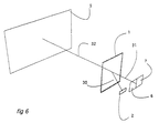
- Figure 6 shows a view of one such arrangement.
- Stereo pair 2 is illuminated such that light 30 passing through the stereo pair 2 is focused by reflection Holographic Optical Element (HOE) 1 the focused light 31 travels towards the viewer and forms diffuse real images 7 and 6 of the diffuse zones 3,4 (not shown) illuminating the two stereo half pictures.
- Light 31 appear to be the continuation of non-existing light 32 apparently emanating from the enlarged virtual image 5 of stereo pair 2.
- HOE 1 should be a full colour reflection hologram made so that it reflects the primary colours used in the stereo pair 2.
- a similar arrangement can be made using a transmission HOE though it this case additional filtering of the light (or use of monochromatic light sources) may be required to obtain a sharp image.
- a mirror can be used in place of the HOE 1 in Figure 6. Ideally this should be an off axis parabolic mirror, though other shapes would also work well enough.
- a lens (or combination of lenses) can be used when the stereo pair 2 is on the opposite side of the optic 1 in Figure 6. If a lens is used the configuration can obviously work on axis.
- compound optics which may be a combination of several optics of similar type (e.g. all lenses) or a different types (e.g. lenses, mirrors and/or diffractive elements).
- Mobile viewing zone solution In order to avoid the requirement of high resolution imposed by a multiple view solution the display can be made with just left and right viewing zones and a means can be provided for moving the position of zones 3 and 4 in response to the viewer's own change of position. This will usually mean moving the illuminating light source (e.g. the position of the source of light 20 in Figure 4 or the projectors in 10l, 10r in Figure 2). This will allow the viewer to move without loss of 3D effect, if the perspectives of the stereo half images are also changed accordingly then the effect of continuous parallax can be achieved.
- the illuminating light source e.g. the position of the source of light 20 in Figure 4 or the projectors in 10l, 10r in Figure 2. This will allow the viewer to move without loss of 3D effect, if the perspectives of the stereo half images are also changed accordingly then the effect of continuous parallax can be achieved.
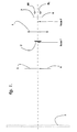
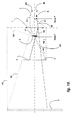
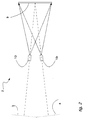
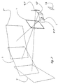
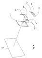
- Figures 7, 8 and 9 show ways of achieving multiple and or mobile viewing zones in one embodiment of the invention. Similar methods can be applied to other embodiments.
Landscapes
- Physics & Mathematics (AREA)
- General Physics & Mathematics (AREA)
- Optics & Photonics (AREA)
- Diffracting Gratings Or Hologram Optical Elements (AREA)
- Testing, Inspecting, Measuring Of Stereoscopic Televisions And Televisions (AREA)
- Measuring Pulse, Heart Rate, Blood Pressure Or Blood Flow (AREA)
- Fittings On The Vehicle Exterior For Carrying Loads, And Devices For Holding Or Mounting Articles (AREA)
- Stereoscopic And Panoramic Photography (AREA)
Description
- The optical element 1 can be made as an HOE with
multiple focal points, thereby generating
multiple viewing positions. This is illustrated
in Figure 7 where the holographic optical
element is made with three foci. (E.g. by
providing three object beams and one reference
beam). The approximate location of the
initial viewing zones optic 2 produces three sets of images. Threevirtual images viewing zones - The holographic element(s) used to generate the
diffuse
zones real images - Multiple diffuse
zones zone pair viewing zones corresponding viewing zones
Claims (18)
- A stereoscopic display device comprising:wherein said means and said optical element are arranged and constructed such that the optical element (1) forms a real image (6, 7) of the viewing zones and a virtual image (5) of the viewable images whereby each of the virtual images is visible to a viewer only where a light ray (50) can be traced from the viewer's eye through the real image of the associated viewing zone (6,7), the optical element (1) and the corresponding viewable image, and characterised in that the means for generating a plurality of viewable images comprises image bearing means (2) which lies between the optical element (1) and the back focal point (f) of the optical element.a) means (2) for generating a plurality of viewable images, each viewable image comprising a different perspective view of a common scene;b) means for generating a plurality of viewing zones (3,4) each for viewing one of the viewable images, the viewing zones being so arranged such that in use each of a viewer's eyes (8R,8L) sees a different viewable image thereby enabling the viewer to enjoy a stereoscopic 3D image of the common scene; andc) an optical element (1) with positive optical power;
- A display device according to claim 1, wherein the viewable images are displayed on one image bearing means (14) such that parts (15) of the said image bearing means display one image and other parts (16) other images, and the said image bearing means (14) is combined with a viewing zone determining optical device (12) whereby the light passing through the parts (15) displaying one image form a viewing zone remote from the image bearing means and light passing through the parts (16) displaying other images also form remote viewing zones such that each respective viewing zone forms in a different position with respect to the other viewing zones.
- A display device according to claim 1 or 2, wherein the viewable images are formed by separate image bearing means (25,26) and wherein the images are projected onto a view determining screen such that the viewing zone associated with each image forms in a different position to the viewing zones associated with each other image.
- A display device according to any of the preceding claims, wherein the means for generating one or more zones comprises an array of lenses.
- A display device according to any of the preceding claims, wherein the means for generating one or more viewing zones comprises a holographic optical element (17) which produces diffuse viewing zones either as real images or as virtual images in the first instance.
- A display device according to claim 3, wherein the view determining screen comprises a holographic optical element (17) which produces diffuse viewing zones combined with at least a diffraction grating so as to effect dispersion compensation.
- A display device according to any of the preceding claims, wherein the viewable images are formed by separate image bearing means (25,26) and a further optical means (27) such as a beamsplitter disposed to overlay the said image bearing means so that they appear both to be located in the same position.
- A display device according to claim 7, wherein each image bearing means is associated with an additional viewing zone determining optical device, such that the viewing zone may be a real image or a virtual image in the first instance.
- A display device according to claim 8, wherein the viewing zone determining optical devices comprise holographic optical elements which produce diffuse images such that in use the viewing zones associated with each viewable image form in different positions.
- A display device according to any of the preceding claims, wherein the viewing zone generating means comprises a holographic optical element (17) which forms the respective viewing zones as diffuse virtual images.
- A display device according to any of the preceding claims, wherein the viewing zone generating means comprises a holographic optical element (17) which forms the respective viewing zones as diffuse real images.
- A display device according to any of the preceding claims, wherein the means for generating the viewable images generates the viewable images sequentially.
- A display device according to claim 12, wherein the viewable images are displayed on image bearing means and the image bearing means is combined with an optical element which forms a viewing zone remote from the image bearing means; the position of said viewing zone being dependant upon the position of a source of light illuminating the optical element whereby there is provided at least one light source for each separate viewable image and viewing zone required, the whole being arranged so that when one viewable image is displayed then the illuminating light causes the viewing zone to form in one position and when a second viewable image is displayed a different light illuminates the optical element causing a second viewing zone to form in a different position, the sequential display of successive images and the associated forming of viewing zones being achieved fast enough for persistence of vision to prevent the viewer from perceiving the flickering of any of the images.
- A display device according to any of the above claims, whereby the means for generating one or more viewable images are constituted by liquid crystal display means (14).
- A display device according to claim 13, wherein the positions of the light sources used to illuminate the image bearing means can be altered so as to move the position of the viewing zones in use.
- A display device according to claim 15, wherein the light sources move in a manner such that the viewing zones move to follow the movement of the viewer's head so that the viewer can move without losing the stereoscopic effect.
- A display device according to any of the above claims, whereby each viewable image is associated with more than one viewing zone thereby permitting more than one viewer to use the display at any one time.
- A display device according to any of the preceding claims, wherein the optical element is a reflection or transmission Holographic Optical Element HOE, a lens or a mirror or any combination thereof.
Applications Claiming Priority (3)
| Application Number | Priority Date | Filing Date | Title |
|---|---|---|---|
| GB9511519 | 1995-06-07 | ||
| GBGB9511519.2A GB9511519D0 (en) | 1995-06-07 | 1995-06-07 | Autostereoscopic display with enlargeable image volume |
| PCT/GB1996/001378 WO1996041228A1 (en) | 1995-06-07 | 1996-06-07 | Display device |
Publications (2)
| Publication Number | Publication Date |
|---|---|
| EP0830630A1 EP0830630A1 (en) | 1998-03-25 |
| EP0830630B1 true EP0830630B1 (en) | 2000-09-06 |
Family
ID=10775669
Family Applications (1)
| Application Number | Title | Priority Date | Filing Date |
|---|---|---|---|
| EP96917574A Expired - Lifetime EP0830630B1 (en) | 1995-06-07 | 1996-06-07 | Stereoscopic display device |
Country Status (12)
| Country | Link |
|---|---|
| US (1) | US6078423A (en) |
| EP (1) | EP0830630B1 (en) |
| JP (1) | JP4045347B2 (en) |
| KR (1) | KR100391388B1 (en) |
| CN (1) | CN1162732C (en) |
| AU (1) | AU701192B2 (en) |
| CA (1) | CA2220466C (en) |
| DE (1) | DE69610206T2 (en) |
| ES (1) | ES2151663T3 (en) |
| GB (1) | GB9511519D0 (en) |
| RU (1) | RU2181902C2 (en) |
| WO (1) | WO1996041228A1 (en) |
Families Citing this family (13)
| Publication number | Priority date | Publication date | Assignee | Title |
|---|---|---|---|---|
| US6525699B1 (en) | 1998-05-21 | 2003-02-25 | Nippon Telegraph And Telephone Corporation | Three-dimensional representation method and an apparatus thereof |
| EP1252756B1 (en) * | 2000-01-25 | 2006-05-31 | NewSight GmbH | Method and system for the three-dimensional representation |
| KR100349206B1 (en) * | 2000-07-04 | 2002-09-05 | 삼성전자 주식회사 | A stereoscopic video display system using a polarization characteristic of liquid crystal type display panel |
| US20030122925A1 (en) * | 2001-08-17 | 2003-07-03 | Byoungyi Yoon | Method and system for providing the motion information of stereoscopic cameras |
| US7708640B2 (en) * | 2002-02-15 | 2010-05-04 | Wms Gaming Inc. | Gaming machine having a persistence-of-vision display |
| US6724991B1 (en) | 2003-02-13 | 2004-04-20 | Eastman Kodak Company | Binocularly viewable holographic viewfinder and camera |
| DE10325146A1 (en) | 2003-05-30 | 2004-12-16 | X3D Technologies Gmbh | Method and arrangement for spatial representation |
| RU2490817C2 (en) * | 2008-02-11 | 2013-08-20 | Конинклейке Филипс Электроникс Н.В. | Autostereoscopic image output device |
| EP2340648B1 (en) * | 2008-10-28 | 2019-12-11 | Koninklijke Philips N.V. | A three dimensional display system |
| US20120092339A1 (en) * | 2009-06-26 | 2012-04-19 | Koninklijke Philips Electronics N.V. | Multi-view autostereoscopic display device |
| PL3716620T3 (en) * | 2009-07-27 | 2023-06-12 | Koninklijke Philips N.V. | Switching between 3d video and 2d video |
| DE102010018083B4 (en) * | 2010-04-23 | 2013-05-08 | Tridelity Ag | Simultaneous reproduction of a plurality of images by means of a two-dimensional image representation matrix |
| CN103947198B (en) * | 2011-01-07 | 2017-02-15 | 索尼电脑娱乐美国公司 | Dynamic adjustment of predetermined three-dimensional video settings based on scene content |
Family Cites Families (11)
| Publication number | Priority date | Publication date | Assignee | Title |
|---|---|---|---|---|
| US3447854A (en) * | 1965-08-18 | 1969-06-03 | Kollsman Instr Corp | Three-dimensional viewer |
| US3802769A (en) * | 1972-08-28 | 1974-04-09 | Harris Intertype Corp | Method and apparatus for unaided stereo viewing |
| US4535354A (en) * | 1983-03-24 | 1985-08-13 | Rickert Glenn E | Projected stereoscopic picture separation |
| US4799739A (en) * | 1987-08-10 | 1989-01-24 | Advanced Dimensional Displays, Inc. | Real time autostereoscopic displays using holographic diffusers |
| GB8917611D0 (en) * | 1989-08-01 | 1989-09-13 | Cohen Godfrey M | Improvements in or relating to stereo viewers |
| GB9115394D0 (en) * | 1991-07-16 | 1991-09-04 | Richmond Holographic Res | Viewing apparatus |
| US5379133A (en) * | 1992-06-19 | 1995-01-03 | Atl Corporation | Synthetic aperture based real time holographic imaging |
| US5418584A (en) * | 1992-12-31 | 1995-05-23 | Honeywell Inc. | Retroreflective array virtual image projection screen |
| GB9304944D0 (en) * | 1993-03-11 | 1993-04-28 | Pilkington Perkin Elmer Ltd | Head-up displays |
| GB2284068A (en) * | 1993-11-12 | 1995-05-24 | Sharp Kk | Three-dimensional projection display apparatus |
| US5774261A (en) * | 1993-11-19 | 1998-06-30 | Terumo Kabushiki Kaisha | Image display system |
-
1995
- 1995-06-07 GB GBGB9511519.2A patent/GB9511519D0/en active Pending
-
1996
- 1996-06-07 JP JP50023997A patent/JP4045347B2/en not_active Expired - Fee Related
- 1996-06-07 ES ES96917574T patent/ES2151663T3/en not_active Expired - Lifetime
- 1996-06-07 AU AU60102/96A patent/AU701192B2/en not_active Ceased
- 1996-06-07 EP EP96917574A patent/EP0830630B1/en not_active Expired - Lifetime
- 1996-06-07 WO PCT/GB1996/001378 patent/WO1996041228A1/en active IP Right Grant
- 1996-06-07 CA CA002220466A patent/CA2220466C/en not_active Expired - Fee Related
- 1996-06-07 CN CNB961944919A patent/CN1162732C/en not_active Expired - Fee Related
- 1996-06-07 KR KR1019970709020A patent/KR100391388B1/en not_active IP Right Cessation
- 1996-06-07 RU RU98100453/28A patent/RU2181902C2/en not_active IP Right Cessation
- 1996-06-07 DE DE69610206T patent/DE69610206T2/en not_active Expired - Lifetime
-
1997
- 1997-06-07 US US08/973,516 patent/US6078423A/en not_active Expired - Fee Related
Also Published As
| Publication number | Publication date |
|---|---|
| CA2220466C (en) | 2007-08-28 |
| GB9511519D0 (en) | 1995-08-02 |
| JPH11504729A (en) | 1999-04-27 |
| DE69610206D1 (en) | 2000-10-12 |
| RU2181902C2 (en) | 2002-04-27 |
| CN1187250A (en) | 1998-07-08 |
| DE69610206T2 (en) | 2001-01-04 |
| WO1996041228A1 (en) | 1996-12-19 |
| AU6010296A (en) | 1996-12-30 |
| CN1162732C (en) | 2004-08-18 |
| AU701192B2 (en) | 1999-01-21 |
| CA2220466A1 (en) | 1996-12-19 |
| US6078423A (en) | 2000-06-20 |
| ES2151663T3 (en) | 2001-01-01 |
| KR100391388B1 (en) | 2003-11-20 |
| JP4045347B2 (en) | 2008-02-13 |
| KR19990022539A (en) | 1999-03-25 |
| EP0830630A1 (en) | 1998-03-25 |
Similar Documents
| Publication | Publication Date | Title |
|---|---|---|
| EP0602934B1 (en) | Autostereoscopic directional display apparatus | |
| US5703717A (en) | Three-dimensional projection display apparatus | |
| US5465175A (en) | Autostereoscopic display device | |
| EP2160905B1 (en) | Multi-user autostereoscopic display | |
| EP0601308B1 (en) | Stereoscopic television display | |
| JP2891177B2 (en) | 3D display device | |
| JP3642736B2 (en) | Directional display | |
| JP3269823B2 (en) | Optical system for two-dimensional and three-dimensional display of information | |
| EP0830630B1 (en) | Stereoscopic display device | |
| Woodgate et al. | Autostereoscopic 3D display systems with observer tracking | |
| JP3105888B2 (en) | Multi-view 3D video display | |
| JP3462796B2 (en) | Three-dimensional display method and device | |
| JP3022559B1 (en) | 3D display system | |
| Dolgoff | Real-depth imaging: a new 3D imaging technology with inexpensive direct-view (no glasses) video and other applications | |
| GB2273577A (en) | Autostereoscopic directional display apparatus | |
| KR20000039515A (en) | Display device for three dimensional image | |
| Brar et al. | Helium3D: a laser-based 3D display with'3D+'Capability | |
| KR100233801B1 (en) | Image display apparatus for displaying plane and three dimensional images | |
| Takada | Optical Characteristics of Glassless 3D Display using Retroreflection and Narrow-angle Diffusion | |
| Jönsson | State-of-the-art in holography and auto-stereoscopic displays | |
| Surman et al. | HELIUM3D: A laser-scanned head-tracked autostereoscopic display |
Legal Events
| Date | Code | Title | Description |
|---|---|---|---|
| PUAI | Public reference made under article 153(3) epc to a published international application that has entered the european phase |
Free format text: ORIGINAL CODE: 0009012 |
|
| 17P | Request for examination filed |
Effective date: 19971230 |
|
| AK | Designated contracting states |
Kind code of ref document: A1 Designated state(s): BE DE ES FR GB IE IT NL |
|
| RTI1 | Title (correction) |
Free format text: STEREOSCOPIC DISPLAY DEVICE |
|
| GRAG | Despatch of communication of intention to grant |
Free format text: ORIGINAL CODE: EPIDOS AGRA |
|
| 17Q | First examination report despatched |
Effective date: 19991011 |
|
| GRAG | Despatch of communication of intention to grant |
Free format text: ORIGINAL CODE: EPIDOS AGRA |
|
| GRAH | Despatch of communication of intention to grant a patent |
Free format text: ORIGINAL CODE: EPIDOS IGRA |
|
| GRAH | Despatch of communication of intention to grant a patent |
Free format text: ORIGINAL CODE: EPIDOS IGRA |
|
| GRAA | (expected) grant |
Free format text: ORIGINAL CODE: 0009210 |
|
| AK | Designated contracting states |
Kind code of ref document: B1 Designated state(s): BE DE ES FR GB IE IT NL |
|
| ITF | It: translation for a ep patent filed |
Owner name: BUZZI, NOTARO&ANTONIELLI D'OULX |
|
| REF | Corresponds to: |
Ref document number: 69610206 Country of ref document: DE Date of ref document: 20001012 |
|
| REG | Reference to a national code |
Ref country code: IE Ref legal event code: FG4D |
|
| ET | Fr: translation filed | ||
| REG | Reference to a national code |
Ref country code: ES Ref legal event code: FG2A Ref document number: 2151663 Country of ref document: ES Kind code of ref document: T3 |
|
| PLBE | No opposition filed within time limit |
Free format text: ORIGINAL CODE: 0009261 |
|
| STAA | Information on the status of an ep patent application or granted ep patent |
Free format text: STATUS: NO OPPOSITION FILED WITHIN TIME LIMIT |
|
| 26N | No opposition filed | ||
| REG | Reference to a national code |
Ref country code: GB Ref legal event code: IF02 |
|
| PGFP | Annual fee paid to national office [announced via postgrant information from national office to epo] |
Ref country code: NL Payment date: 20081203 Year of fee payment: 13 Ref country code: IE Payment date: 20081216 Year of fee payment: 13 |
|
| PGFP | Annual fee paid to national office [announced via postgrant information from national office to epo] |
Ref country code: ES Payment date: 20081218 Year of fee payment: 13 |
|
| PGFP | Annual fee paid to national office [announced via postgrant information from national office to epo] |
Ref country code: IT Payment date: 20081224 Year of fee payment: 13 |
|
| PGFP | Annual fee paid to national office [announced via postgrant information from national office to epo] |
Ref country code: BE Payment date: 20090112 Year of fee payment: 13 |
|
| BERE | Be: lapsed |
Owner name: *RICHMOND HOLOGRAPHIC RESEARCH & DEVELOPMENT LTD Effective date: 20090630 |
|
| NLV4 | Nl: lapsed or anulled due to non-payment of the annual fee |
Effective date: 20100101 |
|
| REG | Reference to a national code |
Ref country code: IE Ref legal event code: MM4A |
|
| PG25 | Lapsed in a contracting state [announced via postgrant information from national office to epo] |
Ref country code: IE Free format text: LAPSE BECAUSE OF NON-PAYMENT OF DUE FEES Effective date: 20090608 |
|
| PG25 | Lapsed in a contracting state [announced via postgrant information from national office to epo] |
Ref country code: BE Free format text: LAPSE BECAUSE OF NON-PAYMENT OF DUE FEES Effective date: 20090630 |
|
| PG25 | Lapsed in a contracting state [announced via postgrant information from national office to epo] |
Ref country code: NL Free format text: LAPSE BECAUSE OF NON-PAYMENT OF DUE FEES Effective date: 20100101 |
|
| REG | Reference to a national code |
Ref country code: ES Ref legal event code: FD2A Effective date: 20090608 |
|
| PG25 | Lapsed in a contracting state [announced via postgrant information from national office to epo] |
Ref country code: ES Free format text: LAPSE BECAUSE OF NON-PAYMENT OF DUE FEES Effective date: 20090608 |
|
| PGFP | Annual fee paid to national office [announced via postgrant information from national office to epo] |
Ref country code: FR Payment date: 20101115 Year of fee payment: 15 |
|
| PGFP | Annual fee paid to national office [announced via postgrant information from national office to epo] |
Ref country code: DE Payment date: 20101020 Year of fee payment: 15 |
|
| PG25 | Lapsed in a contracting state [announced via postgrant information from national office to epo] |
Ref country code: IT Free format text: LAPSE BECAUSE OF NON-PAYMENT OF DUE FEES Effective date: 20090607 |
|
| PGFP | Annual fee paid to national office [announced via postgrant information from national office to epo] |
Ref country code: GB Payment date: 20101020 Year of fee payment: 15 |
|
| GBPC | Gb: european patent ceased through non-payment of renewal fee |
Effective date: 20110607 |
|
| REG | Reference to a national code |
Ref country code: FR Ref legal event code: ST Effective date: 20120229 |
|
| REG | Reference to a national code |
Ref country code: DE Ref legal event code: R119 Ref document number: 69610206 Country of ref document: DE Effective date: 20120103 |
|
| PG25 | Lapsed in a contracting state [announced via postgrant information from national office to epo] |
Ref country code: DE Free format text: LAPSE BECAUSE OF NON-PAYMENT OF DUE FEES Effective date: 20120103 Ref country code: FR Free format text: LAPSE BECAUSE OF NON-PAYMENT OF DUE FEES Effective date: 20110630 |
|
| PG25 | Lapsed in a contracting state [announced via postgrant information from national office to epo] |
Ref country code: GB Free format text: LAPSE BECAUSE OF NON-PAYMENT OF DUE FEES Effective date: 20110607 |