EP0828397A2 - Method of determining the number of times a pager has been paged and a pager having such a function - Google Patents
Method of determining the number of times a pager has been paged and a pager having such a function Download PDFInfo
- Publication number
- EP0828397A2 EP0828397A2 EP97306908A EP97306908A EP0828397A2 EP 0828397 A2 EP0828397 A2 EP 0828397A2 EP 97306908 A EP97306908 A EP 97306908A EP 97306908 A EP97306908 A EP 97306908A EP 0828397 A2 EP0828397 A2 EP 0828397A2
- Authority
- EP
- European Patent Office
- Prior art keywords
- message
- pager
- detected
- message number
- estimating
- Prior art date
- Legal status (The legal status is an assumption and is not a legal conclusion. Google has not performed a legal analysis and makes no representation as to the accuracy of the status listed.)
- Withdrawn
Links
Images

Classifications
-
- H—ELECTRICITY
- H04—ELECTRIC COMMUNICATION TECHNIQUE
- H04W—WIRELESS COMMUNICATION NETWORKS
- H04W88/00—Devices specially adapted for wireless communication networks, e.g. terminals, base stations or access point devices
- H04W88/02—Terminal devices
- H04W88/022—Selective call receivers
- H04W88/023—Selective call receivers with message or information receiving capability
-
- G—PHYSICS
- G08—SIGNALLING
- G08B—SIGNALLING OR CALLING SYSTEMS; ORDER TELEGRAPHS; ALARM SYSTEMS
- G08B5/00—Visible signalling systems, e.g. personal calling systems, remote indication of seats occupied
- G08B5/22—Visible signalling systems, e.g. personal calling systems, remote indication of seats occupied using electric transmission; using electromagnetic transmission
- G08B5/222—Personal calling arrangements or devices, i.e. paging systems
- G08B5/223—Personal calling arrangements or devices, i.e. paging systems using wireless transmission
- G08B5/224—Paging receivers with visible signalling details
- G08B5/229—Paging receivers with visible signalling details with other provisions not elsewhere provided for
Definitions
- the present invention relates generally to a radio pager, and more specifically to a method of determining or estimating, within a pager, the number of times paging services have been implemented by a calling station. Still more specifically, the present invention relates to a pager which can determine or estimate the number of paging service times (viz., the number of message transmissions).
- a paging service company typically charges each subscriber a fixed fee for their services irrespective of the number of paging services during a predetermined time period (e.g., one month). However, some paging service companies intend to charge the subscriber depending on the number of messages which are transmitted (viz., the number of pagings). In such a case, it is desirable if the subscriber is able to determine or estimate the service fee without inquiring the fee from the company.
- a predetermined number is counted down each time the subscriber's pager receives a message. When the countdown reaches zero, the pager alerts the subscriber.
- Another object of embodiments of the present invention is to provide a pager which has a function of estimating or determining the number of messages which have been transmitted.
- Embodiments of the present invention are concerned with techniques wherein, in order to estimate the number of message transmissions at a radio pager wherein messages transmitted are sequentially numbered, a transmitted signal is acquired which has been found to be directed to the pager. Thereafter, a check is made to determine if a message number included in the transmitted signal is detected. If the message number is detected, it is stored in a memory. The number of acquired transmitted signals is incremented except in the case that the message number detected is discontinuous with a message number which was detected immediately before. In this instance, the number of message transmissions is estimated or determined using the number of acquired transmitted signals, the message number of the just received message, and the message number of the previously received message.
- One aspect of the present invention resides in a method of estimating the number of message transmissions at a radio pager wherein the messages transmitted are sequentially numbered, comprising the steps of: (a) acquiring a transmitted signal which has been found to be directed to the pager; (b) detecting a message number included in the transmitted signal if the message number can be detected; (c) storing the message number detected at step (b); (d) incrementing the number of acquired -transmitted signals except where the message number detected at step (b) is discontinuous with a previous message number which was detected immediately before the message number detected at step (b); and (e) estimating the number of message transmissions using the number of acquired transmitted signals, the message number detected at step (b), and the previous message number.
- a pager having an estimating function for estimating the number of message transmissions, comprising: a signal acquiring circuit for acquiring a transmitted signal which has been found to be directed to the pager; first means for detecting a message number included in the transmitted signal if the message number can be detected; memory means for storing the message number detected by the first means; second means for incrementing the number of acquired transmitted signals except where the message number detected at the first means is discontinuous with a previous message number which was detected immediately before; and third means for estimating the number of message transmission times using the number of acquired transmitted signals, the message number detected by the first means, and the previous message number.
- a pager calling station associated with the present invention is such as to sequentially number each of the messages transmitted therefrom.
- the sequential numbers may be cyclically used from one up to a predetermined number (e.g., ten thousand (for example)).
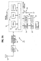
- a front end 12 is provided for amplifying and demodulating a code-modulated carrier wave received by an antenna 14.
- the front end 12 is a conventional circuit arrangement comprised of a high frequency amplifier, a frequency converter, an IF (intermediate frequency) amplifier, and a discriminator.
- a high frequency amplifier a high frequency amplifier
- a frequency converter a frequency converter
- IF intermediate frequency amplifier
- discriminator a discriminator
- the front end 12 is periodically energized by a plurality of preamble search pulses that are applied thereto under the control of a pager controller 16.
- the output of the front end 12 is applied to a decoder 18 after being wave-shaped at a wave shaper (not shown).
- the decoder 18 searches for a preamble and a synchronization codeword preceded thereby. If the codeword is detected, the decoder 20 searches for an identifying address code by comparing the same with a subscriber's unique code prestored in a ROM (read only memory) (not shown) within the decoder 18. In the event that the identifying address code coincides with the subscriber's unique code, the decoder 18 supplies the pager control section 16 with data that includes the message data and the associated message number.
- a CPU 20 central processing unit 20 activates an alert unit 22 such as a speaker, an LED (light emitting diode), and a vibrator by way of an alert unit driver 24. Further, the message directed to the subscriber is exhibited on a display 26 via a display driver 28.
- a function switch 30 is coupled to the control section 16.
- the pager control section 16 includes, in addition to the CPU 20, a ROM (read only memory) 32, a RAM (random access memory) 34, and a clock 36.
- the ROM 32 is previously provided with a program that controls the overall operations of the pager 10.
- the RAM (random access memory) 34 provides work spaces needed for pager operations, which will be discussed later in detail.
- the clock 36 provides the CPU 20 with the time data of months, days, and hours.
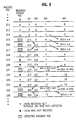
- a plurality of memory sections M0-M4 of the RAM 34 are schematically illustrated.
- the memory section M0 is for storing a message received by the pager 10.
- M1 and M2 are provided for alternately storing message numbers attached to the received messages.
- M3 stores the number of received messages, while M4 is a working space for estimating or determining the number of message transmission times (viz., paging times of the calling station).
- a notation * in Fig. 3 denotes that the message data was received but the message number attached thereto was not detected.
- a notation ⁇ in Fig. 3 indicates that the data itself was not received due to signal degradation during transmission. This case occurs when the pager 10 is not energized or located in an area wherein the pager is unable to receive the paging signal due to an environment of poor signal strength.
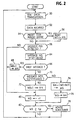
- the pager 10 is waiting for data transmission. It is assumed that the pager 10 acquires, at step 52, a message data transmitted from a calling station. In this instance, it is understood that the pager 10 has already specified that a transmitted identification address code coincided with the subscriber's unique code.
- a check is made to determine if a predetermined time period has expired. It may be convenient to design the pager 10 such as to cyclically check, using the clock 36, if a new month has begun. This is because it appears preferable that the subscriber is charged for the paging service every month. Of course, the present invention is not limited to such a time period. As mentioned above, the calling station attaches sequential message numbers to the messages, respectively. The sequential numbers does not start from one at each month and thus, it is not possible to determine the number of paging services during one month merely using the sequential numbers.
- step 54 determines that the preset time period has expired at step 54 (viz., YES)
- the memory sections M1-M4 are all cleared at step 56. If the answer to the inquiry at step 54 is negative, the routine goes to step 58.
- the memory sections M1-M4 are cleared at this time. As shown in Fig. 3, when M1-M4 are cleared, it is assumed that the paging number is 212.
- a check is made to determine if a message number is detected or specified. If the pager 10 fails to detect any message number that the calling station has attached to the received message, the routine proceeds to step 60 whereat the content of M3 is incremented by one. Therefore, at this stage, the content of M3 becomes *1". For the sake of simplifying the descriptions, each of M1-M4 also indicates the content of thereof. Subsequently, at step 62, a check is made to determine if M3 is equal to or greater than a predetermined number (Np). This number is previously set to a suitable paging number such as 50 merely by way of example. At this stage, since M3 ⁇ Np, the routine goes back to step 50. More specifically, for example, the initial paging services up to 50 times are covered by a basic fee, after which the service fee increases stepwise each time the number of paging services reaches 50 times.
- Np predetermined number
- step 58 the program goes to step 64 whereat the paging No. 215 is stored in M1.
- the pager 10 detects the paging No. 216 that is in turn stored in the memory section M2.
- the instant message is the second one whose paging No. has been detected and thus, the routing goes to step 70 whereat a check is made to determine if the just detected message number immediately follows the previously detected number. Since the answer to the inquiry at step 70 is affirmative, the value of M3+1 is stored, at step 72, into the memory section M4 whose value therefore becomes "5".
- the pager 10 detects the paging No. 217 that is stored into the memory section M1. It is understood that the incoming paging numbers are alternately stored into M1 and M2. Thereafter, the operation similar to the above is implemented. Thus, each of the contents of M3 and M4 becomes "6".
- the pager fails to detect the paging No. 218 although the message itself is received. Thus, only the content of M3 is incremented by one.
- the pager 10 fails to acquire any data and accordingly, all M1-M4 remain unchanged.
- the routine proceeds to step 74 whereat a calculation of (M4+
- 10.
- a message "The service fee increases thereafter" (for example) is displayed at step 78.
- the new service fee for up to the following 50 paging services may be displayed.
- the alert device such as a speaker.
Abstract
Description
Claims (10)
- A method of estimating the number of message transmissions at a radio pager wherein messages transmitted are sequentially numbered, comprising the steps of:(a) acquiring a transmitted signal which has been found to be directed to the pager;(b) detecting a message number included in the transmitted signal if the message number can be detected;(c) storing the message number detected at step (b);(d) incrementing the number of acquired transmitted signals except where the message number detected at step (b) is discontinuous with a previous message number which was detected immediately before; and(e) estimating the number of message transmission times using the number of acquired transmitted signals, the message number detected at step (b), and the previous message number.
- A method as claimed in claim 1, wherein the number of message transmissions is exhibited on a pager's display upon reaching a predetermined value.
- A method as claimed in claim 1, wherein the step of estimating the number of message transmissions restarts when a predetermined time period expires.
- A method as claimed in daim 3, wherein the predetermined time period is one month.
- A method as claimed in claim 4, wherein the predetermined time period is determined using a clock that is provided in the pager.
- A pager having a function of estimating the number of message transmissions, comprising:a signal acquiring circuit for acquiring a transmitted signal which has been found to be directed to the pager;first means for detecting a message number included in the transmitted signal if the message number can be detected;memory means for storing the message number detected at said first means;second means for incrementing the number of acquired transmitted signals except where the message number detected at said first means is discontinuous with a previous message number which was detected immediately before; andthird means for estimating the number of message transmissions using the number of acquired transmitted signals, the message number detected at said first means, and the previous message number.
- A pager as claimed in claim 6, further including a display on which the number of message transmission times is exhibited upon reaching a predetermined value.
- A pager as claimed in claim 6, wherein estimating the number of message transmission times restarts when a predetermined time period expires.
- A pager as claimed in claim 8, wherein the predetermined time period is one month.
- A pager as claimed in claim 9, further comprising a clock which determines the predetermined time period.
Applications Claiming Priority (3)
| Application Number | Priority Date | Filing Date | Title |
|---|---|---|---|
| JP23707996 | 1996-09-06 | ||
| JP237079/96 | 1996-09-06 | ||
| JP8237079A JP2845831B2 (en) | 1996-09-06 | 1996-09-06 | Radio selective call receiver |
Publications (2)
| Publication Number | Publication Date |
|---|---|
| EP0828397A2 true EP0828397A2 (en) | 1998-03-11 |
| EP0828397A3 EP0828397A3 (en) | 1999-09-15 |
Family
ID=17010110
Family Applications (1)
| Application Number | Title | Priority Date | Filing Date |
|---|---|---|---|
| EP97306908A Withdrawn EP0828397A3 (en) | 1996-09-06 | 1997-09-05 | Method of determining the number of times a pager has been paged and a pager having such a function |
Country Status (4)
| Country | Link |
|---|---|
| US (1) | US6078267A (en) |
| EP (1) | EP0828397A3 (en) |
| JP (1) | JP2845831B2 (en) |
| CN (1) | CN1177263A (en) |
Families Citing this family (2)
| Publication number | Priority date | Publication date | Assignee | Title |
|---|---|---|---|---|
| US7190956B2 (en) * | 2001-05-15 | 2007-03-13 | Motorola Inc. | Instant message proxy for circuit switched mobile environment |
| US20050021651A1 (en) * | 2003-07-24 | 2005-01-27 | International Business Machines Corporation | Method and system for identification and presentation of statistical usage data for messaging systems |
Citations (5)
| Publication number | Priority date | Publication date | Assignee | Title |
|---|---|---|---|---|
| GB2154347A (en) * | 1984-02-14 | 1985-09-04 | Nec Corp | Paging communication system |
| JPS63142927A (en) * | 1986-12-05 | 1988-06-15 | Nec Corp | Radio selective call information receiver |
| GB2253503A (en) * | 1990-11-30 | 1992-09-09 | Nec Corp | Radio pager with data display device |
| EP0622765A1 (en) * | 1993-04-26 | 1994-11-02 | Nec Corporation | Lost call detection display pager with repeat call discrimination capability |
| EP0827122A1 (en) * | 1996-08-27 | 1998-03-04 | Nec Corporation | A pager terminal |
Family Cites Families (4)
| Publication number | Priority date | Publication date | Assignee | Title |
|---|---|---|---|---|
| US5682148A (en) * | 1985-11-27 | 1997-10-28 | Seiko Corporation | Paging system with message numbering prior to transmission |
| US5086428A (en) * | 1989-06-09 | 1992-02-04 | Digital Equipment Corporation | Reliable broadcast of information in a wide area network |
| US5151899A (en) * | 1991-02-11 | 1992-09-29 | Digital Equipment Corporation | Tracking sequence numbers in packet data communication system |
| US5796790A (en) * | 1995-03-24 | 1998-08-18 | Telefonaktiebolaget L M Ericsson | Reliable related billing ID information method for call delivery |
-
1996
- 1996-09-06 JP JP8237079A patent/JP2845831B2/en not_active Expired - Fee Related
-
1997
- 1997-09-05 US US08/923,985 patent/US6078267A/en not_active Expired - Fee Related
- 1997-09-05 EP EP97306908A patent/EP0828397A3/en not_active Withdrawn
- 1997-09-08 CN CN97116277A patent/CN1177263A/en active Pending
Patent Citations (5)
| Publication number | Priority date | Publication date | Assignee | Title |
|---|---|---|---|---|
| GB2154347A (en) * | 1984-02-14 | 1985-09-04 | Nec Corp | Paging communication system |
| JPS63142927A (en) * | 1986-12-05 | 1988-06-15 | Nec Corp | Radio selective call information receiver |
| GB2253503A (en) * | 1990-11-30 | 1992-09-09 | Nec Corp | Radio pager with data display device |
| EP0622765A1 (en) * | 1993-04-26 | 1994-11-02 | Nec Corporation | Lost call detection display pager with repeat call discrimination capability |
| EP0827122A1 (en) * | 1996-08-27 | 1998-03-04 | Nec Corporation | A pager terminal |
Non-Patent Citations (1)
| Title |
|---|
| PATENT ABSTRACTS OF JAPAN vol. 012, no. 403 (E-674), 26 October 1988 (1988-10-26) & JP 63 142927 A (NEC CORP), 15 June 1988 (1988-06-15) * |
Also Published As
| Publication number | Publication date |
|---|---|
| EP0828397A3 (en) | 1999-09-15 |
| US6078267A (en) | 2000-06-20 |
| CN1177263A (en) | 1998-03-25 |
| JP2845831B2 (en) | 1999-01-13 |
| JPH1084566A (en) | 1998-03-31 |
Similar Documents
| Publication | Publication Date | Title |
|---|---|---|
| CA2134729C (en) | Location dependent information receiving device and method | |
| JP3110173B2 (en) | Reception control method of radio selective calling receiver | |
| RU98119398A (en) | METHOD AND DEVICE FOR CARRYING OUT THE SELECTION OF A PREFERRED SYSTEM | |
| RU98119440A (en) | METHOD AND DEVICE FOR CARRYING OUT THE SELECTION OF A PREFERRED SYSTEM | |
| JP3108567B2 (en) | Mobile radio system and mobile receiver | |
| US6078267A (en) | Method of determining the number of times a pager has been paged and a pager having such a function | |
| KR0150928B1 (en) | Selective paging receiver with message display function and control method of message display of this selective paging receiver | |
| WO2002067484A3 (en) | System and method for determining a location of an event using a base station | |
| US5463368A (en) | Method of setting an inaudible alert mode in a radio pager | |
| JP3071716B2 (en) | Information receiving device | |
| US5572197A (en) | Lost call detection display pager with repeat call discrimination capability | |
| US6052564A (en) | Portable individual calling device | |
| AU661498B2 (en) | A Method of Allocating Pager Channels to a Plurality of Paging Areas in a Multi-Channel Radio Pager Network | |
| US5881092A (en) | Spread spectrum telecommunication system | |
| EP0592180A1 (en) | Paging receiver | |
| JP2001266294A (en) | Device for notifying vehicle accident | |
| US6115582A (en) | Radio selective-calling receiver | |
| EP0726684A2 (en) | Intermittent receiving control apparatus of a selective calling receiver | |
| EP0831441A1 (en) | Radio selective calling receiver and method of judging received data | |
| EP0607037B1 (en) | Radio paging receiver | |
| EP0791905B1 (en) | Paging system | |
| JPH1127736A (en) | Position retrieval system | |
| JPS62194750A (en) | Radio calling system receiver | |
| EP0856997A2 (en) | Radio selective call receiver | |
| JP4712299B2 (en) | Position detection device |
Legal Events
| Date | Code | Title | Description |
|---|---|---|---|
| PUAI | Public reference made under article 153(3) epc to a published international application that has entered the european phase |
Free format text: ORIGINAL CODE: 0009012 |
|
| AK | Designated contracting states |
Kind code of ref document: A2 Designated state(s): FR GB |
|
| AX | Request for extension of the european patent |
Free format text: AL;LT;LV;RO;SI |
|
| PUAL | Search report despatched |
Free format text: ORIGINAL CODE: 0009013 |
|
| AK | Designated contracting states |
Kind code of ref document: A3 Designated state(s): AT BE CH DE DK ES FI FR GB GR IE IT LI LU MC NL PT SE |
|
| AX | Request for extension of the european patent |
Free format text: AL;LT;LV;RO;SI |
|
| 17P | Request for examination filed |
Effective date: 19990818 |
|
| AKX | Designation fees paid | ||
| RBV | Designated contracting states (corrected) |
Designated state(s): FR GB |
|
| REG | Reference to a national code |
Ref country code: DE Ref legal event code: 8566 |
|
| STAA | Information on the status of an ep patent application or granted ep patent |
Free format text: STATUS: THE APPLICATION HAS BEEN WITHDRAWN |
|
| 18W | Application withdrawn |
Withdrawal date: 20020925 |