EP0828362A2 - Asynchronous transfer mode network providing stable connection quality - Google Patents
Asynchronous transfer mode network providing stable connection quality Download PDFInfo
- Publication number
- EP0828362A2 EP0828362A2 EP19970306909 EP97306909A EP0828362A2 EP 0828362 A2 EP0828362 A2 EP 0828362A2 EP 19970306909 EP19970306909 EP 19970306909 EP 97306909 A EP97306909 A EP 97306909A EP 0828362 A2 EP0828362 A2 EP 0828362A2
- Authority
- EP
- European Patent Office
- Prior art keywords
- connection
- transfer mode
- network
- asynchronous transfer
- mode network
- Prior art date
- Legal status (The legal status is an assumption and is not a legal conclusion. Google has not performed a legal analysis and makes no representation as to the accuracy of the status listed.)
- Withdrawn
Links
Images


Classifications
-
- H—ELECTRICITY
- H04—ELECTRIC COMMUNICATION TECHNIQUE
- H04Q—SELECTING
- H04Q11/00—Selecting arrangements for multiplex systems
- H04Q11/04—Selecting arrangements for multiplex systems for time-division multiplexing
- H04Q11/0428—Integrated services digital network, i.e. systems for transmission of different types of digitised signals, e.g. speech, data, telecentral, television signals
- H04Q11/0478—Provisions for broadband connections
-
- H—ELECTRICITY
- H04—ELECTRIC COMMUNICATION TECHNIQUE
- H04L—TRANSMISSION OF DIGITAL INFORMATION, e.g. TELEGRAPHIC COMMUNICATION
- H04L12/00—Data switching networks
- H04L12/54—Store-and-forward switching systems
- H04L12/56—Packet switching systems
- H04L12/5601—Transfer mode dependent, e.g. ATM
- H04L2012/5614—User Network Interface
-
- H—ELECTRICITY
- H04—ELECTRIC COMMUNICATION TECHNIQUE
- H04L—TRANSMISSION OF DIGITAL INFORMATION, e.g. TELEGRAPHIC COMMUNICATION
- H04L12/00—Data switching networks
- H04L12/54—Store-and-forward switching systems
- H04L12/56—Packet switching systems
- H04L12/5601—Transfer mode dependent, e.g. ATM
- H04L2012/5629—Admission control
- H04L2012/5631—Resource management and allocation
- H04L2012/5632—Bandwidth allocation
-
- H—ELECTRICITY
- H04—ELECTRIC COMMUNICATION TECHNIQUE
- H04L—TRANSMISSION OF DIGITAL INFORMATION, e.g. TELEGRAPHIC COMMUNICATION
- H04L12/00—Data switching networks
- H04L12/54—Store-and-forward switching systems
- H04L12/56—Packet switching systems
- H04L12/5601—Transfer mode dependent, e.g. ATM
- H04L2012/5638—Services, e.g. multimedia, GOS, QOS
- H04L2012/5646—Cell characteristics, e.g. loss, delay, jitter, sequence integrity
- H04L2012/5651—Priority, marking, classes
Definitions
- This invention relates to an asynchronous transfer mode (ATM) network having a network controller which controls quality of connections in the ATM network.
- ATM asynchronous transfer mode
- An ATM network of a specific type has a plurality of ATM exchangers each of which is connected to at least one of the other exchangers and to a plurality of terminal equipment units.
- a network controller is connected to all of the exchangers so as to control admitting and releasing connections between the terminal equipment units.
- the network controller prevents or solves congestion of traffic on connections at each of the exchangers so as to keep predetermined quality of the connections.
- the network controller When the network controller receives a call from one of the terminal equipment units, the network controller decides whether or not an empty bandwidth exists which is wide enough for admission of a new connection required by the call. Namely, the network controller decides whether or not the congestion is caused to occur by the admission of the new connection.
- the network controller operates according to priority of the new connection. Specifically, the network controller searches connections which do not have priority over the new connection from existing connections. Then, the network controller, for example, disconnects one or more of searched connections to admit the new connection. Moreover, there is another case that the network controller limits a bandwidth of one of the searched connections so as to admit the new connection. In addition, there is still another case that the network controller discards cells which are transmitted through one of the searched connections so as to admit the new connection.
- the network controller searches connections which have the lowest priority among the existing connections. Then, the network controller regulates one of the searched connections in the manner mentioned above to prevent the congestion.
- the bandwidth of each connection is decided by the network controller.
- the new connection is not always given the bandwidth requested by the call signal.
- Specific embodiments of this invention aim to provide an ATM network which enables designation of a bandwidth from a terminal equipment.
- Another aim of embodiments of this invention is to provide an ATM network of the type described which keeps a bandwidth stable until an end of transmission.
- a further aim of embodiments of this invention is to provide an ATM network of the type described which accomplishes stable connection quality.
- an asynchronous transfer mode network has exchange, which is connected to a plurality of terminal equipment units, for admitting a connection in response to a call signal sent from one of the terminal equipment units.
- the asynchronous transfer mode network comprises a network controller which is connected to both the exchange and to the terminal equipment units by logic transmission line circuits for receiving the call signal and for judging whether or not the connection can be admitted in the asynchronous transfer mode network to order the exchange to admit the connection.
- a known ATM network 101of a specific type has cell assemble and disassemble sections 102a and 102b which are connected to terminal equipment units T1 - Ti and Tj - Tn, respectively.
- An ATM transmission path 103 is connected between the cell assemble and disassemble sections 102a and 102b.
- Band width limiting sections 104a and 104b are connected to the cell assemble and disassemble sections 102a and 102b, respectively.
- a call control section 105 is connected to both of the cell assemble and disassemble sections 102a and 102b.
- a bandwidth managing section 106 is connected to the bandwidth limiting sections 104a and 104b and the call control section 105.
- the known ATM network 101 admits a new connection which has priority over existing connections even when an empty bandwidth is not wide enough. Operation of the known ATM network 101 will be described soon.
- Each of the terminal equipment units T1 - Ti and Tj -Tn issues a call when a request is made about admission of a connection between itself and one of the other terminal equipment units.
- the terminal equipment which makes the call sends cells to the call control section 105 through the cell assemble and disassemble section 102a or 102b.
- Each cell includes own and the other's attribute data and predetermined parameters.
- the call control section 105 decides priority of the new connection and a necessary bandwidth for the new connection in response to the attribute data and the parameters included in the cells and reports the priority and the necessary bandwidth to the bandwidth managing section 106.
- the bandwidth managing section 106 judges whether or not the new connection can be admitted in the ATM transmission path 103. In other words, judgment is made in the bandwidth managing section 106 about whether or not the ATM transmission path 103 has the empty bandwidth which is wider than the necessary bandwidth of the new connection. If the ATM transmission path 103 has the empty bandwidth wider than the necessary bandwidth, the bandwidth managing section 106 assigns the empty bandwidth to the new connection. As a result, the new connection is admitted in the known ATM network and is established in the ATM transmission path 103.
- the bandwidth managing section 106 searches existing connections each of which does not have priority over the new connection and has a wide bandwidth wider than the necessary bandwidth.
- the band width managing section 106 selects one from the searched existing connections. Then, the bandwidth managing section 106 deprive a part or all of the wide bandwidth of one of the existing connections to assign the new connection. Consequently, the new connection is established in the ATM transmission path 103.
- the known ATM network 101 allows that the new connection having higher priority is preferentially established in the ATM transmission path 103.
- the bandwidth of each connection is assigned by the bandwidth managing section 106 and can not be designated from each of the terminal terminal equipment units T1 - Ti and Tj - Tn.
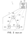
- an ATM network a has ATM exchangers 201, 202, and 203 and network controller 204 which has a control area ⁇ including the ATM exchangers 201, 202, and 203 and which has a connection attribute table 205.
- the ATM exchangers 201, 202, and 203 located within the control area will be collectively called an exchange section.
- the ATM exchangers 201, 202, and 203 are connected to one another by physical transmission line circuits 206, 207, and 208 and are connected to the network controller 204 by logical transmission line circuits 206, 207, and 208, respectively.
- the ATM exchangers 201, 202, and 203 report occurrence of congestion of traffic therein to the network controller 204. If the network controller 204 receives the report from one of the ATM exchangers 201, 202, and 203, it searches a connection having the lowest priority among existing connections passing through the ATM exchangers with reference to the connection attribute table 205. If such a connection of the lowest priority is present, the network controller 204 orders the ATM exchanger to abandon cells related to the lowest priority connection. As a result, traffic is regulated and the congestion is solved in the ATM exchanger.
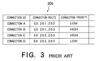
- connection attribute table 205 has contents as shown in Fig. 3 and that the congestion of traffic occurs at the ATM exchanger 201.
- the ATM exchanger 201 reports the occurrence of the congestion to the network controller 204 through the logic transmission line circuit 209.
- the network controller 204 looks up connections A and B which pass through the ATM exchanger 201 and selects the connection A of lower priority with reference to the connection attribute table 205. Then, the network controller 204 orders the ATM exchangers 201 and 202 which are concerned with the connection A to partly or wholly abandon cells on the connection A or to disconnect the connection A. Therefore, the congestion is solved in the known ATM network.
- each of the connections may be regulated by occurrence of the congestion.
- each connection is released from the known ATM network ⁇ .
- ATM synchronous transfer mode
- the ATM network 401 comprises a plurality of ATM network exchangers 402 each of which is connected to at least one of the others by ATM line circuits 403.
- a network controller 404 is connected to the ATM network exchangers 402 through logic transmission line circuits 405.
- Each of the logic transmission line circuits 405 may be an ATM line circuit, another exclusive line circuit, etc.
- a plurality of terminal equipment units 406 are connected to the ATM network 401.
- Each of the terminal equipment units 406 is connected to one of the ATM exchangers 402 by ATM line circuits 407 and connected to the network controller 404 through logic transmission line circuits 408.
- Each of the ATM line circuits 407 may not be always connected to the terminal equipment units 406 directly.
- each of the ATM line circuits 407 may be connected to a network termination apparatus (not shown), such as an ATM router, which is connected to the terminal equipment units 406 through another line circuits (not shown).
- each of the logic transmission line circuits 408 may be an ATM line circuit, another exclusive line circuit, etc.
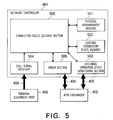
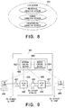
- the network controller 404 has a physical arrangement memory 501 which memorizes physical arrangement information representative of physical arrangement of the ATM exchangers 402 and the terminal equipment units 406.
- An existing connection state memory 502 memorizes existing connection state information which includes items of a route, a bandwidth, a network class, etc. concerning each of existing connections.
- An exchanger operation state monitoring section 503 monitors an operation state of each ATM exchanger 402 through the logic transmission line circuits 405.
- a call signal receiver 504 receives a call signal sent from each terminal equipment unit 406 through the logic transmission line circuits 408. The call signal requests the network controller 404 to admit a new connection.
- a connection route deciding section 505 is connected to the physical arrangement memory 501, the existing connection state memory 502,the exchanger operation state monitoring section 503, and the call signal receiver 504.
- the connection route deciding section 505 decides a route of the new connection in response to the call signal with reference to the physical arrangement information, the exchanger operation state, and existing connection state information. In consequence, the connection route deciding section 505 produces an admission signal which is representative of the route.
- a ordering section 506 is connected to the connection route deciding section 505 and orders the ATM exchangers 402 arranged on the route to admit the new connection in response to the admission signal.
- the ordering section 506 reports admission of the new connection to the existing connection state memory 502 and the terminal equipment units 406 concerning to the new connection.
- Each of the terminal equipment units 406 has a connection request section (not shown) which produces the call signal to request the network controller 404 to admit the new connection in the ATM network 401.
- the call signal has a parameter which includes an address of a destination terminal equipment unit, a necessary bandwidth of the new connection, and a network class of the new connection.
- the call signal may include connection route data. However, the following description will be made on the assumption that the call signal includes no connection route data.
- the network class is classified into three classes or levels as illustrated in Fig. 6.
- One of the classes is a preferential connection class while another one is a normal connection class and the remaining one is an unpreferential connection class. From this fact, it is to be noted that the normal connection class is defined in the example illustrated.
- a first connection concerned with the unpreferential connection class is admitted into the ATM network 401 when an empty bandwidth is wider than the necessary bandwidth.
- the first connection can be forcibly released by the network controller 404 so that a second connection concerned with the preferential connection class is admitted into the ATM network 401.
- the second connection is admitted into the ATM network 401 when the empty bandwidth is wider than the necessary bandwidth or when the empty bandwidth becomes wider than the necessary bandwidth by releasing the first connection.
- the second connection is kept intact with a bandwidth held until the end.
- a third connection concerned with the normal connection class is admitted into the ATM network 401 when the empty bandwidth is wider than the necessary bandwidth.
- the third connection is kept intact with a bandwidth held until the end like the second connection.
- the network class shows priority of the connection.
- fees for the connections mentioned above become high as the priority becomes high. Accordingly, even if the fees are pertinently determined, consideration should be made about desirable ratios of preferential connection, normal connection, and unpreferential connection so as to appropriately distribute each connection.
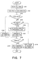
- the network controller 404 operates in the manner illustrated in Fig. 7.
- the call signal receiver 504 receives the call signal sent from one of the terminal equipment units 406 (Step S701).
- the call signal receiver 504 reports the receipt of the call signal and sends the parameter included in the call signal to the connection route deciding section 505.
- the connection route deciding section 505 has routing data concerning each of the terminal equipment units 406 so as to decide the route in response to the parameter at the step S702.
- the routing data include a plurality of optional routes which are given priority and which corresponds to the new connection.
- the connection route deciding section 505 selects one from the optional routes according to the priority and judges with reference to the physical arrangement information and the existing connection state information whether or not the selected optional route includes the empty bandwidth wider than the necessary bandwidth.
- the connection route deciding section 505 also judges whether or not a fault occurs at the ATM exchangers 402 arranged on the selected optional routes.
- the connection route deciding section 505 repeats this operation until it finds an optimum route which has the empty bandwidth wider than the necessary bandwidth and which does not pass through the faulty ATM exchanger 402.
- the connection route deciding section 505 stops the operation when the optimum route is not found from the optional routes.
- the connection route deciding section 505 judges that the new connection can be admitted in the ATM network 401 at the step S703. Then, the connection route deciding section 505 notifies the ordering section 506 of the optimum route together with the necessary bandwidth.
- the ordering section 506 orders the ATM exchangers 402 arranged on the optimum route to admit the new connection with the necessary bandwidth (Step S704).
- connection route deciding section 505 judges that the new connection can not be admitted in the ATM network 401 at the step S703. Then, the connection route deciding section 505 confirms the network class which is included in the parameter (Step S705).
- step S705 jumps to the step S710.
- connection route deciding section 505 directs the ordering section 506 to release the existing connections of the unpreferential network class.
- the existing connections of the unpreferential network class are established through various combinations of the ATM exchangers 402 which will be called specific ATM exchangers hereinunder.
- the network controller 404 operates in the following manner.
- the ordering section 506 orders the specific ATM exchangers 402 to release the existing connections of the unpreferential network class in response to a direction or command supplied from the connection route deciding section 505.
- the specific ATM exchangers 402 release all of the existing connections of the unpreferential network class in response to an order supplied from the ordering section 506 (Step S706). In this state, the existing connection state information is renewed.
- connection route deciding section 505 selects one from the optional routes according to the priority, it is presumed that the specific ATM exchangers 402 are all arranged on the selected one of the optional routes. In this case, additional steps (not shown) like the step S702 and S703 are carried out. If the optimum route is not found in the additional steps, the step S706 and the additional steps are repeated until the optimum route is found or all of the optional routes are selected by the connection route deciding section 505.
- connection route deciding section 505 may select one of the optional routes that will have an empty bandwidth wider than the necessary bandwidth by releasing the connection of unpreferential class.
- connection route deciding section 505 searches the optimum route from the optional routes like the step S702 and notifies the ordering section 506 of the searched optimum route. However, in case that the optional route is selected so as to release the connections of the unpreferential network class, the connection route deciding section 505 notifies the ordering section 506 of the selected route which will have empty bandwidth wider than the necessary bandwidth.
- the ordering section 506 orders the ATM exchangers 402 arranged on the optimum route to admit the new connection. Each of the ATM exchangers 402 admits the new connection in response to the order of the ordering section 506 (Step S707). Then, the ATM exchangers 402 report the result of the admitting operation to the ordering section 506.
- the ordering section 506 renews the existing connection state information of the existing connection state memory 502 through the connection route deciding section 505, when the result shows that the new connection is admitted into the ATM network 401 (Step S708). Moreover, the ordering section 506 notifies the terminal equipment unit 406 produces the call signal of completion of admission of the new connection (Step S709).
- the ordering section 506 notifies failure of admission of the new connection to the terminal equipment unit 406 which produce the call signal (Step S710).
- the network controller 404 controls the new connection and the existing connection in response to the call signal. Accordingly, if the call signal includes the network class which indicative of the preferential network class, admission probability of the new connection is high under a situation of bandwidth insufficiency. Moreover, if the call signal includes the network class which is indicative of the normal network class, the bandwidth of the new connection admitted into the ATM network 401 is kept intact until the end. In addition, if the call signal includes the network class which is indicative of the unpreferential network class, the fee is suppressed although the new connection may be forcibly released. Therefore, the ATM network system seems to form three networks which have quality of service levels different from one another as shown in Fig. 8.
- the ATM network 901 has the same structure as the ATM network 401 illustrated in Fig. 1 without a network controller 902.
- the network controller 902 has a network control section 903 which is connected to the ATM exchangers 402 through the logic transmission line circuits 405 and which corresponds to the network controller 404 of Fig. 1.
- a service control section 904 is connected to the network control section and the terminal equipment units 406 through the logic transmission line circuits 408 to simplify handling of each terminal equipment units 406.
- the service control section 904 has a memory (not shown) which memorizes a plurality of the parameters together with service names.
- the terminal equipment unit 406 When the terminal equipment unit 406 requests the ATM network to admit the new connection, it produces the call signal which includes one of the service names in place of a combination of the address of the destination terminal equipment unit, the necessary bandwidth of the new connection, and the network class of the new connection.
- the service name is simpler than the parameter mentioned in conjunction with Fig.5.
- the call signal is transmitted to the service control section 904 through the logic transmission line circuit 408.
- the service control section 904 receives the call signal including the service name and searches one of the parameters from the memory in response to the service name.
- the service control section 904 sends the searched parameter to the network control section 903.
- the network control section 903 operates like the network controller 404 of Fig. 1 in response to the parameter.
- data of the optional route may be memorized in the memory of the service control section.
- the handling becomes easy in each of the terminal equipment unit 406, because the service name alone is sent from the terminal equipment unit 406 to access the service control section which memorizes the parameters for admission of the new connection.
Landscapes
- Engineering & Computer Science (AREA)
- Computer Networks & Wireless Communication (AREA)
- Data Exchanges In Wide-Area Networks (AREA)
Abstract
Description
Claims (11)
- An asynchronous transfer mode network (401) having exchanging means (402), which is connected to a plurality of terminal equipment units (406), for admitting a connection in response to a call signal sent from one of said terminal equipment units, characterized by:
network control means (404) connected to both said exchanging means and to said terminal equipment units by logic transmission line circuits (405, 408) for receiving said call signal and for judging whether or not said connection can be admitted in said asynchronous transfer mode network to order said exchanging means to admit said connection. - An asynchronous transfer mode network as claimed in claim 1, characterized in that said exchanging means includes a plurality of asynchronous transfer mode exchangers each of which is connected to at least one of other asynchronous transfer mode exchangers and to said network control means.
- An asynchronous transfer mode network as claimed in claim 1, characterized in that said call signal includes a predetermined parameter representative of a network connection class.
- An asynchronous transfer mode network as claimed in claim 3, characterized in that said network control means further comprises service control means for memorizing said predetermined parameter with parameter name, said call signal including said parameter name in place of said predetermined parameter.
- An asynchronous transfer mode network as claimed in claim 3, characterized in that said network connection class is classified into a preferential connection class, a normal connection class, and unpreferential connection class.
- An asynchronous transfer mode network as claimed in claim 5, characterized in that said normal connection class provides said connection which is kept intact with a bandwidth held until the end of said connection when said connection is admitted in said asynchronous transfer mode network once.
- An asynchronous transfer mode network as claimed in claim 5, characterized in that said preferential connection class provides said connection which is more preferentially admitted than said unpreferential connection class.
- An asynchronous transfer mode network as claimed in claim 1, said network control means characterized in that:physical arrangement memorizing means (501) for memorizing physical arrangement information representative of a physical arrangement of both said exchanging means and said terminal equipment units,existing connection state memorizing means (502) for memorizing existing connection state information which includes routes and priority of existing connections which are being admitted in said asynchronous transfer mode network,monitoring means connected to said exchanging means (503) through said logic transmission line circuits for monitoring operation state of said exchanging means,receiving means (504) connected to said terminal equipment units by said logic transmission line circuits for receiving said call signal to produce a report signal representative of receiving said call signal,judging means (505) connected to said physical arrangement memorizing means, said existing connection state memorizing means, said monitoring means, and said receiving means for judging whether or not said connection can be admitted in said asynchronous transfer mode network in response to said report signal with reference to said physical arrangement, said existing connection state information, and said operation state to decide a route of said connection and to produce an admission signal when said connection can be admitted in said asynchronous transfer mode network, andordering means (506) connected to said judging means and said exchanging means for ordering said exchangeing means to admit said connection in said route in response to said admission signal.
- A method of admitting a connection into an asynchronous transfer mode network in response to a call signal supplied from one of terminal equipment units which is connected to exchange of said asynchronous transfer mode network, said method comprising the steps of:receiving said call signal by a network controller which is connected to said exchange and said terminal equipment units through logic transmission line circuits,judging at said network controller whether said connection required by said call signal can be admitted in said asynchronous transfer mode network or not,ordering said exchanging means to admit said connection in said asynchronous transfer mode network when said network controller judges that said connection can be admitted in said asynchronous transfer mode network, andadmitting said connection in said asynchronous transfer mode network.
- A method of admitting connection into an asynchronous transfer mode network in response to a call signal supplied from one of terminal equipment units which is connected to exchanging means of said asynchronous transfer mode network, said method comprising the steps of:memorizing a physical arrangement of both said exchanging means and said terminal equipment units,memorizing existing connection state information which includes routes and priority of existing connections which are being admitted in said asynchronous transfer mode network,monitoring an operation state of said exchanging means,receiving said call signal to produce a report signal representative of receiving said call signal,judging whether or not said connection can be admitted in said asynchronous transfer mode network in response to said report signal with reference to said physical arrangement, said existing connection state information, and said operation state to decided a route of said connection and to produce an admission signal when said connection can be admitted in said asynchronous transfer mode network,ordering said exchangeing means to admit said connection in said route of said asynchronous transfer mode network in response to said admission signal, andadmitting said connection in said asynchronous transfer mode network.
- A method as claimed in Claim 10, said call signal including a parameter representative of a network connection class which is classified into a preferential connection class, a normal connection class, and an unpreferential connection class, wherein said method further comprising the steps of:recognizing said network connection class when said connection can not be admitted in said asynchronous transfer mode network,releasing predetermined existing connections which belong to the unpreferential connection class, when said network connection class is representative of said preferential connection class, andadmitting said connection in said asynchronous transfer mode network.
Applications Claiming Priority (3)
| Application Number | Priority Date | Filing Date | Title |
|---|---|---|---|
| JP23636296A JP3394394B2 (en) | 1996-09-06 | 1996-09-06 | Network connection quality control method |
| JP236362/96 | 1996-09-06 | ||
| JP23636296 | 1996-09-06 |
Publications (2)
| Publication Number | Publication Date |
|---|---|
| EP0828362A2 true EP0828362A2 (en) | 1998-03-11 |
| EP0828362A3 EP0828362A3 (en) | 1999-08-11 |
Family
ID=16999681
Family Applications (1)
| Application Number | Title | Priority Date | Filing Date |
|---|---|---|---|
| EP19970306909 Withdrawn EP0828362A3 (en) | 1996-09-06 | 1997-09-05 | Asynchronous transfer mode network providing stable connection quality |
Country Status (4)
| Country | Link |
|---|---|
| US (1) | US6552999B2 (en) |
| EP (1) | EP0828362A3 (en) |
| JP (1) | JP3394394B2 (en) |
| CA (1) | CA2211457C (en) |
Cited By (2)
| Publication number | Priority date | Publication date | Assignee | Title |
|---|---|---|---|---|
| WO1999066690A1 (en) * | 1998-06-12 | 1999-12-23 | Telefonaktiebolaget Lm Ericsson (Publ) | Data network communications |
| WO2002030149A1 (en) * | 2000-10-06 | 2002-04-11 | France Telecom | Control unit in a private atm terminal installation |
Families Citing this family (22)
| Publication number | Priority date | Publication date | Assignee | Title |
|---|---|---|---|---|
| WO2000008812A1 (en) * | 1998-08-04 | 2000-02-17 | At & T Corp. | A method for allocating network resources |
| DE19936080A1 (en) * | 1999-07-30 | 2001-02-15 | Siemens Ag | Multiprocessor system for performing memory accesses to a shared memory and associated method |
| KR20010011744A (en) * | 1999-07-30 | 2001-02-15 | 김진찬 | Method for transitting priorty call in operating position system |
| KR100651373B1 (en) * | 1999-11-24 | 2006-11-28 | 삼성전자주식회사 | A method for avoiding over-flooding due to the address registration from unstable terminals |
| JP2002171254A (en) | 2000-11-30 | 2002-06-14 | Fujitsu Ltd | Network managing device |
| WO2002089377A1 (en) | 2001-04-09 | 2002-11-07 | Objective Interface Systems, Inc. | System, method, and article of manufacture for using a replaceable component to select a replaceable quality of service capable network communication channel component |
| US7321784B2 (en) * | 2001-10-24 | 2008-01-22 | Texas Instruments Incorporated | Method for physically updating configuration information for devices in a wireless network |
| US20030177259A1 (en) * | 2002-02-04 | 2003-09-18 | Wookey Michael J. | Remote services systems data delivery mechanism |
| US20030149889A1 (en) * | 2002-02-04 | 2003-08-07 | Wookey Michael J. | Automatic communication and security reconfiguration for remote services |
| US20030163544A1 (en) * | 2002-02-04 | 2003-08-28 | Wookey Michael J. | Remote service systems management interface |
| US7167448B2 (en) * | 2002-02-04 | 2007-01-23 | Sun Microsystems, Inc. | Prioritization of remote services messages within a low bandwidth environment |
| US20030149740A1 (en) * | 2002-02-04 | 2003-08-07 | Wookey Michael J. | Remote services delivery architecture |
| US20030212738A1 (en) * | 2002-05-10 | 2003-11-13 | Wookey Michael J. | Remote services system message system to support redundancy of data flow |
| US8266239B2 (en) * | 2002-06-27 | 2012-09-11 | Oracle International Corporation | Remote services system relocatable mid level manager |
| US7240109B2 (en) * | 2002-06-27 | 2007-07-03 | Sun Microsystems, Inc. | Remote services system service module interface |
| US7260623B2 (en) * | 2002-06-27 | 2007-08-21 | Sun Microsystems, Inc. | Remote services system communication module |
| US7181455B2 (en) * | 2002-06-27 | 2007-02-20 | Sun Microsystems, Inc. | Bandwidth management for remote services system |
| GB0225359D0 (en) * | 2002-10-31 | 2002-12-11 | British Telecomm | Data accession process |
| US20040236856A1 (en) * | 2003-05-22 | 2004-11-25 | International Business Machines Corporation | Method and apparatus for prioritizing users in a wireless hub |
| JP4867799B2 (en) * | 2007-06-05 | 2012-02-01 | 沖電気工業株式会社 | Crawling method, program and device thereof, agent device, network system |
| JP4972110B2 (en) * | 2009-02-24 | 2012-07-11 | 日本電信電話株式会社 | Bandwidth management apparatus and bandwidth management method |
| WO2013158115A1 (en) * | 2012-04-20 | 2013-10-24 | Hewlett-Packard Development Company, L.P. | Controlling data rates of data flows based on information indicating congestion |
Citations (2)
| Publication number | Priority date | Publication date | Assignee | Title |
|---|---|---|---|---|
| EP0388951A2 (en) * | 1989-03-23 | 1990-09-26 | Nec Corporation | Call control with transmission priority in a packet communication network of an ATM type |
| EP0673138A2 (en) * | 1994-03-17 | 1995-09-20 | Fujitsu Limited | Connection admission control method for ATM network |
Family Cites Families (11)
| Publication number | Priority date | Publication date | Assignee | Title |
|---|---|---|---|---|
| JPH0358646A (en) | 1989-07-27 | 1991-03-13 | Nec Corp | Band assignment system in packet communication network |
| JP2513025B2 (en) | 1989-03-23 | 1996-07-03 | 日本電気株式会社 | Bandwidth allocation method in packet communication network |
| JPH03101440A (en) | 1989-09-14 | 1991-04-26 | Hitachi Ltd | Band assignment system |
| CA2038646C (en) * | 1990-03-20 | 1995-02-07 | Katsumi Oomuro | Atm communication system with optimal traffic control by changing the allocated bandwidth |
| JPH0646082A (en) * | 1992-07-22 | 1994-02-18 | Toshiba Corp | Information transfer control system |
| KR100293920B1 (en) * | 1993-06-12 | 2001-09-17 | 윤종용 | Apparatus and method for controlling traffic of atm user network interface |
| US5784358A (en) * | 1994-03-09 | 1998-07-21 | Oxford Brookes University | Broadband switching network with automatic bandwidth allocation in response to data cell detection |
| US5504744A (en) | 1994-03-09 | 1996-04-02 | British Telecommunications Public Limited Company | Broadband switching network |
| SG43032A1 (en) * | 1994-04-13 | 1997-10-17 | British Telecomm | A communication network control method |
| EP0714192A1 (en) * | 1994-11-24 | 1996-05-29 | International Business Machines Corporation | Method for preempting connections in high speed packet switching networks |
| JPH08181701A (en) | 1994-12-27 | 1996-07-12 | Fujitsu Ltd | Atm exchange network management equipment |
-
1996
- 1996-09-06 JP JP23636296A patent/JP3394394B2/en not_active Expired - Fee Related
-
1997
- 1997-09-05 EP EP19970306909 patent/EP0828362A3/en not_active Withdrawn
- 1997-09-05 CA CA 2211457 patent/CA2211457C/en not_active Expired - Fee Related
- 1997-09-05 US US08/924,530 patent/US6552999B2/en not_active Expired - Fee Related
Patent Citations (2)
| Publication number | Priority date | Publication date | Assignee | Title |
|---|---|---|---|---|
| EP0388951A2 (en) * | 1989-03-23 | 1990-09-26 | Nec Corporation | Call control with transmission priority in a packet communication network of an ATM type |
| EP0673138A2 (en) * | 1994-03-17 | 1995-09-20 | Fujitsu Limited | Connection admission control method for ATM network |
Non-Patent Citations (1)
| Title |
|---|
| BOLLA R ET AL: "AN INTEGRATED DYNAMIC RESOURCE ALLOCATION SCHEME FOR ATM NETWORKS" NETWORKING: FOUNDATION FOR THE FUTURE, SAN FRANCISCO, MAR. 28 - APR. 1, 1993, vol. 3, no. CONF. 12, 28 March 1993, pages 1288-1297, XP000419693 INSTITUTE OF ELECTRICAL AND ELECTRONICS ENGINEERS * |
Cited By (4)
| Publication number | Priority date | Publication date | Assignee | Title |
|---|---|---|---|---|
| WO1999066690A1 (en) * | 1998-06-12 | 1999-12-23 | Telefonaktiebolaget Lm Ericsson (Publ) | Data network communications |
| US6374301B1 (en) | 1998-06-12 | 2002-04-16 | Telefonaktiebolaget Lm Ericsson | Data network communications |
| WO2002030149A1 (en) * | 2000-10-06 | 2002-04-11 | France Telecom | Control unit in a private atm terminal installation |
| FR2815208A1 (en) * | 2000-10-06 | 2002-04-12 | France Telecom | MANAGED IN A PRIVATE TERMINAL INSTALLATION IN ATM MODE |
Also Published As
| Publication number | Publication date |
|---|---|
| JPH1084349A (en) | 1998-03-31 |
| CA2211457A1 (en) | 1998-03-06 |
| US6552999B2 (en) | 2003-04-22 |
| EP0828362A3 (en) | 1999-08-11 |
| JP3394394B2 (en) | 2003-04-07 |
| US20020075800A1 (en) | 2002-06-20 |
| CA2211457C (en) | 2001-11-27 |
Similar Documents
| Publication | Publication Date | Title |
|---|---|---|
| CA2211457C (en) | Asynchronous transfer mode network providing stable connection quality | |
| EP1011230B1 (en) | Method and network node for enhanced routing and reservation protocol | |
| US5953312A (en) | Method and apparatus for determining alternate routes in a network using a connection-oriented protocol | |
| EP0568477B1 (en) | Method and apparatus for optimum path selection in packet transmission networks | |
| US6400681B1 (en) | Method and system for minimizing the connection set up time in high speed packet switching networks | |
| US4920529A (en) | Network control method and apparatus therefor | |
| US5287535A (en) | Switching node in label multiplexing type switching network | |
| US6934249B1 (en) | Method and system for minimizing the connection set up time in high speed packet switching networks | |
| US5856981A (en) | Reliable connection oriented networks | |
| US5590118A (en) | Method for rerouting a data stream | |
| FI117225B (en) | Active / Backup routing system on ATM network | |
| EP0847221B1 (en) | An ATM network controller | |
| US7200110B1 (en) | Method and apparatus for prioritized release of connections in a communications network | |
| US7009934B1 (en) | Method and apparatus for rerouting an optical network upon fault | |
| EP0892566A2 (en) | Congestion control | |
| US6055239A (en) | Control method for establishing a permanent virtual connection in an ATM network | |
| US7656820B2 (en) | Data transmission apparatus capable of dividing network areas | |
| JP2861959B2 (en) | ATM network congestion control system | |
| JP4456589B2 (en) | How to optimize the network recovery route | |
| EP1289208B1 (en) | A method of controlling data routing on a network | |
| JP3206544B2 (en) | Virtual Path Bandwidth Change System in Asynchronous Transfer Mode Switching Network | |
| US6714547B1 (en) | Quality-ensuring routing technique | |
| KR100231714B1 (en) | Path Calculation Algorithm with multiple Quality of Service Constraints | |
| EP0699006A1 (en) | Method for rerouting a data stream | |
| US6845101B1 (en) | Method and a network for ATM switching |
Legal Events
| Date | Code | Title | Description |
|---|---|---|---|
| PUAI | Public reference made under article 153(3) epc to a published international application that has entered the european phase |
Free format text: ORIGINAL CODE: 0009012 |
|
| AK | Designated contracting states |
Kind code of ref document: A2 Designated state(s): GB SE |
|
| AX | Request for extension of the european patent |
Free format text: AL;LT;LV;RO;SI |
|
| PUAL | Search report despatched |
Free format text: ORIGINAL CODE: 0009013 |
|
| AK | Designated contracting states |
Kind code of ref document: A3 Designated state(s): AT BE CH DE DK ES FI FR GB GR IE IT LI LU MC NL PT SE |
|
| AX | Request for extension of the european patent |
Free format text: AL;LT;LV;RO;SI |
|
| 17P | Request for examination filed |
Effective date: 19990705 |
|
| AKX | Designation fees paid | ||
| RBV | Designated contracting states (corrected) |
Designated state(s): GB SE |
|
| REG | Reference to a national code |
Ref country code: DE Ref legal event code: 8566 |
|
| 17Q | First examination report despatched |
Effective date: 20040503 |
|
| STAA | Information on the status of an ep patent application or granted ep patent |
Free format text: STATUS: THE APPLICATION IS DEEMED TO BE WITHDRAWN |
|
| 18D | Application deemed to be withdrawn |
Effective date: 20060411 |