EP0825730A2 - Method and system for controlling uplink power in a high data rate satellite communication system employing on-board demodulation and remodulation - Google Patents
Method and system for controlling uplink power in a high data rate satellite communication system employing on-board demodulation and remodulation Download PDFInfo
- Publication number
- EP0825730A2 EP0825730A2 EP97112404A EP97112404A EP0825730A2 EP 0825730 A2 EP0825730 A2 EP 0825730A2 EP 97112404 A EP97112404 A EP 97112404A EP 97112404 A EP97112404 A EP 97112404A EP 0825730 A2 EP0825730 A2 EP 0825730A2
- Authority
- EP
- European Patent Office
- Prior art keywords
- error rate
- data
- downlink
- data stream
- uplink
- Prior art date
- Legal status (The legal status is an assumption and is not a legal conclusion. Google has not performed a legal analysis and makes no representation as to the accuracy of the status listed.)
- Granted
Links
Images


Classifications
-
- H—ELECTRICITY
- H04—ELECTRIC COMMUNICATION TECHNIQUE
- H04L—TRANSMISSION OF DIGITAL INFORMATION, e.g. TELEGRAPHIC COMMUNICATION
- H04L1/00—Arrangements for detecting or preventing errors in the information received
- H04L1/20—Arrangements for detecting or preventing errors in the information received using signal quality detector
-
- H—ELECTRICITY
- H04—ELECTRIC COMMUNICATION TECHNIQUE
- H04B—TRANSMISSION
- H04B7/00—Radio transmission systems, i.e. using radiation field
- H04B7/14—Relay systems
- H04B7/15—Active relay systems
- H04B7/185—Space-based or airborne stations; Stations for satellite systems
- H04B7/1853—Satellite systems for providing telephony service to a mobile station, i.e. mobile satellite service
- H04B7/18539—Arrangements for managing radio, resources, i.e. for establishing or releasing a connection
- H04B7/18543—Arrangements for managing radio, resources, i.e. for establishing or releasing a connection for adaptation of transmission parameters, e.g. power control
Definitions
- This invention relates generally to satellite communication systems, and more particularly, to a method and system for controlling uplink power in a high data rate satellite communication system that employs on-board demodulation and remodulation.
- Satellite-based systems have been employed for many years to distribute voice, data and video signals for global broadcasting of news and sporting events, for example.
- direct broadcast television systems are available that provide for broadcasting of television signals from up to 100 stations using a single satellite. Individuals install an antenna and a satellite receiver that receives the broadcasts directly by way of the satellite and display them on a television monitor.
- a video telephone system that employs a small (3-4 inch) television monitor in combination with a conventional telephone.
- the video telephone system typically uses fiber optic links to provide a sufficient bandwidth to carry the video along with the voice signals.
- this type of system does not have enough bandwidth to provide for full motion video.
- the assignee of the present invention has developed a high data rate satellite communication system that provides for the communication and distribution of full motion video, voice, and data signals, to provide for a wide array of data communications including personal teleconferencing between individuals.
- This system is disclosed in U.S. patent application Serial No. 08/142,524, filed October 21, 1993, entitled "High Data Rate Satellite Communication System", the contents of which are incorporated herein by reference.
- This high data rate satellite communication system comprises a plurality of very small user terminals (VSAT's) that are linked by and that communicate with each other by way of a satellite relay system.
- VSAT's very small user terminals
- a network control center provides control signals that control the satellite relay system and coordinate linking of terminals to each other.
- the system employs frequency division multiplexing on uplinks from the terminals and the network control center to the satellite relay system.
- the system employs time division multiplexing on downlinks from the satellite relay system to the terminals and the network control center.
- a method for controlling the uplink power in a high data rate satellite communication system utilizing on-board demodulation and remodulation and a plurality of simultaneous uplink users.
- the method includes the step of determining a downlink error rate of the downlink data stream.
- the method also includes the step of determining an end-to-end error rate of the uplink data stream and the downlink data stream.
- the method includes the step of determining an error rate of the uplink based on the downlink error rate and the end-to-end error rate.
- the method includes the step of controlling the power of the uplink based on the error rate of the uplink.
- a system for carrying out the steps of the above described method.
- the system includes means for determining a downlink error rate of the downlink data stream.
- the system also includes means for determining an end-to-end error rate of the uplink data stream and the downlink data stream.
- the system includes means for determining an error rate of the uplink based on the downlink error rate and the end-to-end error rate.
- the system includes a controller for controlling the power of the uplink based on the error rate of the uplink.
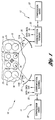
- FIG. 1 illustrates a high data rate satellite communication system 10 in which the present invention may be employed.
- the system 10 comprises a plurality of user terminals (VSAT's) 11,12 (corresponding to first and second user terminals 11,12) that are linked by and that communicate with each other by way of a satellite relay system 13.
- VSAT's user terminals
- the system 10 employs frequency division multiplexing on uplinks from the terminals 11,12 and the network control center 14 to the satellite relay system 13.
- the system 10 employs time division multiplexing on downlinks from the satellite relay system 10 to the terminals 11,12 and the network control center 14.
- Each user terminal 11,12 comprises a data compression coder/decoder (CODEC) circuit 22 for compressing and coding input data and decompressing and decoding output data, a transceiver 23 for modulating and demodulating input and output data, and an antenna 25 for transmitting and receiving encoded data to and from the satellite relay system 13.
- CDEC data compression coder/decoder
- the compression circuit 22 is replaced by interface circuitry that interfaces to a data source, such as a local area network, a terminal or computer, a data communication line, or the like.
- the satellite relay system 13 is typically comprised of a satellite 30, a plurality of receive antennas 32, a plurality of transmit antennas 31, and a signal processor 36. Respective pluralities of feed horns 33,34 are provided to feed data to and from the respective transmit and receive antennas 31,32.
- the plurality of receive antennas 32 operate in a first frequency band and produce a first plurality of beams that cover a predefined area.
- the plurality of receive antennas 32 receive frequency division multiplexed data from the first user terminals 11 on a first beam.
- the plurality of transmit antennas 31 operate in a second frequency band and produce a second plurality of beams that cover the predefined area.
- the plurality of transmit antennas 31 transmit the time division multiplexed data to the second user terminal 12 on a second beam. It is to be understood that the second beam may be geographically colocated with the first beam, depending upon the respective locations of the source and destination user terminals 11,12.
- the signal processor 36 demodulates frequency division multiplexed data received on the first beam from the first user terminal 11, routes the demodulated data so that it is transmitted on the second beam to the second user terminal 12, remodulates the demodulated data to provide encoded data comprising time division multiplexed data, and transmits the frequency division multiplexed data on the second beam to the second user terminal 12.
- FIG. 2 is a block diagram showing a user terminal 11, for example, employed in the system of Figure 1, and in particular the details of the transceiver 23 thereof.
- the transmitter portion of the transceiver 23 it is comprised of a data input port 41 that receives input data, such as video and analog voice signals that have been compressed by the compression circuit 22.
- the components of the transceiver 23 are, generally well known to those skilled in the art, and the functional blocks forming the transceiver 23 may be readily combined to implement the transceiver 23.
- the compressed data is input to an algebraic encoder 42, such as a Reed-Solomon (RS) or a Bose, Chadhuri, Hocquengham (BCH) encoder, and the data may be interleaved by means of an interleaver 43.
- the interleaved data is then convolutionally encoded in a convolutional encoder 44 whereafter it is multiplexed in a multiplexer 45 with control signals 51a and encoding signals 51b generated by a controller 50.
- the multiplexed data is processed by a filtered quadrature phase shift keyed (QPSK) modulator 46 and upconverted by an agile upconverter (U/C) 47.
- QPSK quadrature phase shift keyed
- the upconverted data is then variably attenuated in an uplink power control circuit (ULPC) 48 and amplified by a solid state power amplifier 49.
- the uplink power control circuit (ULPC) 48 mitigates the effect of uplink interference, rain fade, beam roll-off, and the like.
- the amplified data signals are then coupled by way of a diplexer 53 to the antenna 25.
- the receiver portion of the transceiver 23 is comprised of a low noise amplifier (LNA) 54 that is coupled to an output port of the diplexer 53.
- An agile downconverter (D/C) 55 is coupled to the low noise amplifier 54 that downconverts received time domain modulated data and applies it to a QPSK demodulator 56.
- a demultiplexer 57 demultiplexes the received data and strips off time division multiplexed (TDM) channel information 52a and decoding signals 52b that are applied to the controller 50 to control the terminal operation including data rate, uplink frequency and downlink TDM slot selections.
- TDM time division multiplexed
- the demultiplexed data is then decoded in a Viterbi decoder 58 and deinterleaved in a deinterleaver 59.
- the deinterleaved data is then decoded in an algebraic decoder 60, such as a RS or BCH deocoder.
- the algebraic decoder 60 allows recovery of information about the input error rate of the decoder 60. This input error rate is an end-to-end error rate.
- the decoded data is then output from an output port 61 of the transceiver 23.
- the present invention is not limited to the above-described error correction coding circuits and modulation scheme.
- other modulation and/or forward error correction schemes such as RS or BCH codes combined with shifted QPSK (SQPSK) or binary phase shift keying (BPSK) modulation, for example, may be readily employed in the present invention.
- the uplink power control approach of the present invention requires only that the existing circuitry be interfaced with a processor that re-formats the data and transmits it to the originating user terminal 11,12.
- the downlink quality is monitored by measuring the error rate on framing synchronization data contained within the downlink data stream.
- the framing synchronization data are required to allow the receiving terminal 12 (assuming the user terminal 11 is the transmitting terminal) to extract the signal of interest from the time-division multiplexed downlink data stream.
- the framing synchronization data consists of known binary digits that are interleaved into the downlink data stream to identify the timing synchronization of the satellite's on-board multiplexer. Once synchronization is achieved, the receive terminal 12 continues to check the framing data against the known pattern to ensure synchronization has not been lost.
- the uplink power control approach of the present invention utilizes the measured error rate to determine the link quality. Since the framing data are generated on-board satellite 30, the measured error rate is the downlink contribution only.
- the algebraic decoder 60 of the receiver terminal 12 provides the second opportunity to measure link quality.
- the algebraic encoding/decoding process operates on blocks of multi-bit characters. These are frequently 8-bit characters, or bytes, but other sizes may be used.
- redundancy characters are added to blocks of user data characters.
- the RS decoder must determine the number of errors that occur within the codeword. By averaging this number over many codewords, art estimate of input error probability for the RS decoder can be determined. Since the RS encoding/decoding is performed end-to-end on the link, this is a measurement of the overall link quality, i.e., uplink and downlink effects are measured.
- a table look-up is utilized to relate the downlink error rate and the end-to-end error rate to the performance of the uplink of the transmitting terminal 11. The use of the table look-up is explained in conjunction with Figures 3 and 4.
- the horizontal axis represents the downlink error rate, which is estimated by monitoring the framing data.
- the vertical axis represents the input error rate of the algebraic decoder 60, which is estimated by monitoring the decoder error-correction solutions.
- the plotted curve denotes the link error performance without any uplink error contributions. That is, if the uplink is error free and in the absence of measurement errors, this curve shows the correspondence between the downlink (framing data) error measurement and the input character error rate, which is the end-to-end error rate.
- This particular example is for a rate 4/5 convolutional inner code with soft decision Viterbi decode, but similar curves can be calculated for other code rates and types.
- Figure 3 also illustrates two important error rates.
- the horizontal line 90 end-to-end error rate of algebraic decoder 60 defines the target error rate.
- a character error rate of about 0.0013 results in a probability of decoder failure of one in 10 10 codewords.
- the vertical line 92 at a downlink error rate of about 0.0227 depicts the upper limit on the allowable downlink error rate that can allow link closure, i.e., operation of the communication link at a satisfactory error rate.
- a link quality measurement consists of one downlink error rate estimate and one end-to-end error rate estimate. Each measurement can be viewed as a point on the graph shown in Figure 3.
- the uplink power control of the present invention depends on where the measured value falls on the graph of Figure 3. Points to the right of the downlink limit vertical line indicate an inability to achieve link closure due to downlink noise. Repeated measurements in this region mean the link cannot be closed and the call should be terminated. Measurements beneath the curve indicate both some downlink measurement error and little contribution due to uplink. In this case, the uplink power control algorithm of the present invention takes no action.
- Figure 4 maps out the uplink power control algorithm behavior for each region in the plot, including a "no action" region 100, an "abort call” region 102, a “reduce uplink power” region 104, and a “boost uplink power” region 106.
- each measurement may actually be quite noisy, but the measurement rate is quite fast relative to the round-trip delay time. Thus, many measurements may be averaged or voted for each update of the power control loop. If the error rate is lower than required for the desired link performance, the uplink power can be reduced to avoid excessive interference with other system users. This corresponds to the "reduce uplink power" region 104. If the error rate is higher than acceptable, the uplink power will be boosted to overcome link noise and interference.
- the method includes the step of determining a downlink error rate of the downlink data stream, as shown at block 120.
- the downlink error rate is determined by counting errors which occur on predetermined data bits which have been interleaved into the downlink data stream. This is accomplished by time division multiplexing the downlink data stream.
- the time division multiplexed data includes framing synchronization data which is required to allow the receiving terminal 12 to extract the data from the time division multiplexed downlink data stream.
- the method also includes the step of determining an end-to-end error rate of the uplink data stream and the downlink data stream, as shown at block 122.
- RS or BCH encoding/decoding provides the opportunity to measure the quality of the link.
- Blocks of the data in the uplink data stream are encoded to include redundancy characters.
- the blocks of data are decoded to generate decoded blocks of data.
- a number of errors in the data is determined based on the decoded blocks of data and the redundancy characters.
- An error rate of the uplink is then determined based on the downlink error rate and the end-to-end error rate, as shown at block 124.
- the error rate of the uplink is determined based on a predetermined look-up table identifying the relationship between the uplink power, the downlink error rate, and the end-to-end error rate.
- the power of the uplink is then controlled based on the error rate of the uplink, as shown at block 126.
- the method and system of the present invention allow mitigation of system uplink self-interference and eliminate potential system runaway conditions by allowing the uplink to be individually controlled based on constant feedback regarding the performance of the uplink as well as the downlink. Complexity is minimal since the present invention requires only an error counting accumulator to be added to the demultiplexer function of the user terminal. Furthermore, the power control algorithm for the uplink power is modified slightly by adding a table look-up identifying the relationship of downlink error rates and end-to-end error rates with uplink performance.
Landscapes
- Engineering & Computer Science (AREA)
- Computer Networks & Wireless Communication (AREA)
- Signal Processing (AREA)
- Quality & Reliability (AREA)
- Physics & Mathematics (AREA)
- Astronomy & Astrophysics (AREA)
- Aviation & Aerospace Engineering (AREA)
- General Physics & Mathematics (AREA)
- Radio Relay Systems (AREA)
- Mobile Radio Communication Systems (AREA)
Abstract
Description
Claims (10)
- A method for controlling uplink power for signal transmission in a satellite communication system (10) employing on-board demodulation and remodulation and having a plurality of user terminals (11, 12) linked and communicating data by way of a satellite relay system (13), wherein the data is transmitted by an uplink data stream and a downlink data stream, the method comprising the steps of:determining a downlink error rate of the downlink data stream (120);determining an end-to-end error rate of the uplink data stream and the downlink data stream (122);determining an error rate of the signal transmission based on the downlink error rate and the end-to-end error rate (124); andcontrolling the power of the signal transmission based on the error rate of the signal transmission (126).
- The method of claim 1, characterized in that the step (120) of determining the downlink error rate includes the step of counting errors which occur on predetermined data bits which have been interleaved into the downlink data stream.
- The method of claim 2, characterized in that the step of counting includes the step of time division multiplexing the downlink data stream.
- The method of claim 2 or 3, characterized in that the predetermined data bits include framing synchronization data.
- The method of any of claims 1 to 4, characterized in that the step (122) of determining the end-to-end error rate includes the steps of:encoding (42) blocks of the data transmitted by the uplink data stream to include redundant information;decoding (60) the blocks of data in the downlink data stream to generate decoded blocks of data; anddetermining a number of errors in the decoded blocks of data based on the redundant information.
- A system for controlling uplink power for signal transmission in a satellite communication system (10) employing on-board demodulation and remodulation and having a plurality of user terminals (11, 12) linked and communicating data by way of a satellite relay system (13), the plurality of user terminals (11, 12) each having a processor, wherein the data is transmitted by an uplink data stream and a downlink data stream, the system comprising:the processor for determining a downlink error rate of the downlink data stream;an algebraic encoder (42) and algebraic decoder (60) for determining an end-to-end error rate of the uplink data stream and the downlink data stream;the processor for determining an error rate of the signal transmission based on the downlink error rate and the end-to-end error rate; anda controller (48) for controlling the power of the signal transmission based on the error rate of the signal transmission.
- The system of claim 6, characterized in that the processor for determining the downlink error rate includes a counter for counting errors which occur on predetermined data bits which have been interleaved into the downlink data stream.
- The system of claim 7, characterized in that the counter includes a multiplexer (45) for time division multiplexing the downlink data stream.
- The system of claim 7 or 8, characterized in that the predetermined data bits include framing synchronization data.
- The system of any of claims 6 to 9, characterized in that the algebraic encoder (42) and the algebraic decoder (60) comprises:the algebraic encoder (42) for encoding blocks of the data transmitted by the uplink data stream to include redundant information;the algebraic decoder (60) for decoding the blocks of data in the downlink data stream to generate decoded blocks of data; andthe processor for determining a number of errors in the decoded blocks of data based on the redundant information.
Applications Claiming Priority (2)
| Application Number | Priority Date | Filing Date | Title |
|---|---|---|---|
| US700961 | 1996-08-21 | ||
| US08/700,961 US5864547A (en) | 1996-08-21 | 1996-08-21 | Method and system for controlling uplink power in a high data rate satellite communication system employing on-board demodulation and remodulation |
Publications (3)
| Publication Number | Publication Date |
|---|---|
| EP0825730A2 true EP0825730A2 (en) | 1998-02-25 |
| EP0825730A3 EP0825730A3 (en) | 2003-10-08 |
| EP0825730B1 EP0825730B1 (en) | 2006-01-25 |
Family
ID=24815518
Family Applications (1)
| Application Number | Title | Priority Date | Filing Date |
|---|---|---|---|
| EP97112404A Expired - Lifetime EP0825730B1 (en) | 1996-08-21 | 1997-07-19 | Method and system for controlling uplink power in a high data rate satellite communication system employing on-board demodulation and remodulation |
Country Status (3)
| Country | Link |
|---|---|
| US (1) | US5864547A (en) |
| EP (1) | EP0825730B1 (en) |
| DE (1) | DE69735149T2 (en) |
Cited By (4)
| Publication number | Priority date | Publication date | Assignee | Title |
|---|---|---|---|---|
| WO2005046083A1 (en) * | 2003-11-05 | 2005-05-19 | Northrop Grumman Corporation | Communication system and method using time division multiplexed (tdm) downlink |
| WO2010131060A1 (en) * | 2009-05-12 | 2010-11-18 | Datalogic Scanning Group S.R.L. | Method to perform a wireless communication in a data collection system |
| WO2017053274A1 (en) * | 2015-09-23 | 2017-03-30 | Hughes Network Systems, Llc | Modulation and coding for a high altitude platform |
| CN116841920A (en) * | 2017-07-28 | 2023-10-03 | 苹果公司 | System and method for performing memory compression |
Families Citing this family (21)
| Publication number | Priority date | Publication date | Assignee | Title |
|---|---|---|---|---|
| CN1242633C (en) | 1996-11-27 | 2006-02-15 | 株式会社日立制作所 | Transmitting power controlling method, mobile terminal and base table |
| AU1083699A (en) * | 1997-10-20 | 1999-05-10 | Comsat Corporation | Adaptive modulation technique and satellite communication network implementing the same |
| US6070074A (en) * | 1998-04-24 | 2000-05-30 | Trw Inc. | Method for enhancing the performance of a regenerative satellite communications system |
| US6219528B1 (en) * | 1998-06-29 | 2001-04-17 | Hughes Electronics Corporation | Dynamic power control with adaptive reference level |
| US6201786B1 (en) * | 1998-06-29 | 2001-03-13 | Northrop Grumman Corporation | Adaptable and controllable multi-channel data link |
| US6154451A (en) * | 1998-06-29 | 2000-11-28 | Northrop Grumman Corporation | Method for dissemination of multi-sensor products |
| US6335920B1 (en) * | 1998-06-29 | 2002-01-01 | Hughes Electronics Corporation | Satellite-based measurement for uplink power control and time synchronization |
| JP4354041B2 (en) * | 1999-04-30 | 2009-10-28 | 富士通株式会社 | Wireless terminal device |
| US6477182B2 (en) * | 1999-06-08 | 2002-11-05 | Diva Systems Corporation | Data transmission method and apparatus |
| WO2001078250A1 (en) * | 2000-04-06 | 2001-10-18 | Rutgers, The State University Of New Jersey | Method and system for closed loop power control in wireless systems |
| US6760566B1 (en) | 2000-06-19 | 2004-07-06 | Northrop Grumman Corporation | Method and apparatus for controlling a transmission power threshold of a satellite communication system |
| US6430418B1 (en) | 2000-06-19 | 2002-08-06 | Trw Inc. | Method and system for controlling uplink power in a satellite communication system using error leveling |
| US6771929B1 (en) | 2000-10-20 | 2004-08-03 | Northrop Grumman Corporation | Satellite communication system threshold leveling techniques |
| US20040092257A1 (en) * | 2002-11-12 | 2004-05-13 | Chung Kirby J. | Scalable satellite area coverage |
| US20050204258A1 (en) * | 2004-02-13 | 2005-09-15 | Broadcom Corporation | Encoding system and method for a transmitter in wireless communications |
| US8547909B1 (en) * | 2004-02-27 | 2013-10-01 | Sprint Spectrum L.P. | Method and system for dynamic assignment of overhead channel group |
| JP2006311512A (en) * | 2005-03-30 | 2006-11-09 | Toshiba Corp | Transmitter-receiver module and radar equipment with the same |
| US20070206550A1 (en) * | 2006-03-06 | 2007-09-06 | Interdigital Technology Corporation | Method and apparatus for simultaneously processing data in a wireless communication system |
| US8767839B2 (en) * | 2007-01-22 | 2014-07-01 | Qualcomm Incorporated | Error filter to differentiate between reverse link and forward link video data errors |
| US9119092B1 (en) | 2008-05-06 | 2015-08-25 | Sprint Spectrum L.P. | Performance based selection of channel elements for use in a wireless network |
| GB2557628B (en) | 2016-12-13 | 2020-01-01 | Inmarsat Global Ltd | Forward link power control |
Citations (4)
| Publication number | Priority date | Publication date | Assignee | Title |
|---|---|---|---|---|
| US4941199A (en) * | 1989-04-06 | 1990-07-10 | Scientific Atlanta | Uplink power control mechanism for maintaining constant output power from satellite transponder |
| EP0389848A2 (en) * | 1989-03-09 | 1990-10-03 | Fujitsu Limited | Transmission power control system |
| US5446756A (en) * | 1990-03-19 | 1995-08-29 | Celsat America, Inc. | Integrated cellular communications system |
| US5708966A (en) * | 1996-04-04 | 1998-01-13 | Lockheed Martin Corporation | Method and apparatus for performing power control using the wide-band synchronization |
Family Cites Families (5)
| Publication number | Priority date | Publication date | Assignee | Title |
|---|---|---|---|---|
| US4261054A (en) * | 1977-12-15 | 1981-04-07 | Harris Corporation | Real-time adaptive power control in satellite communications systems |
| JPS60190035A (en) * | 1984-03-09 | 1985-09-27 | Nec Corp | Control system of satellite communication transmission power |
| US5473601A (en) * | 1993-10-21 | 1995-12-05 | Hughes Aircraft Company | Frequency reuse technique for a high data rate satellite communication system |
| US5485464A (en) * | 1993-10-21 | 1996-01-16 | Hughes Aircraft Company | Communication protocol for a high data rate satellite communication system |
| JP2877248B2 (en) * | 1994-05-20 | 1999-03-31 | エヌ・ティ・ティ移動通信網株式会社 | Transmission power control method and apparatus in CDMA system |
-
1996
- 1996-08-21 US US08/700,961 patent/US5864547A/en not_active Expired - Lifetime
-
1997
- 1997-07-19 EP EP97112404A patent/EP0825730B1/en not_active Expired - Lifetime
- 1997-07-19 DE DE69735149T patent/DE69735149T2/en not_active Expired - Lifetime
Patent Citations (4)
| Publication number | Priority date | Publication date | Assignee | Title |
|---|---|---|---|---|
| EP0389848A2 (en) * | 1989-03-09 | 1990-10-03 | Fujitsu Limited | Transmission power control system |
| US4941199A (en) * | 1989-04-06 | 1990-07-10 | Scientific Atlanta | Uplink power control mechanism for maintaining constant output power from satellite transponder |
| US5446756A (en) * | 1990-03-19 | 1995-08-29 | Celsat America, Inc. | Integrated cellular communications system |
| US5708966A (en) * | 1996-04-04 | 1998-01-13 | Lockheed Martin Corporation | Method and apparatus for performing power control using the wide-band synchronization |
Non-Patent Citations (1)
| Title |
|---|
| KAZAMA H ET AL: "TRANSMISSION POWER CONTROL FOR TDMA SATELLITE COMMUNICATION SYSTEMS" ELECTRONICS & COMMUNICATIONS IN JAPAN, PART I - COMMUNICATIONS, SCRIPTA TECHNICA. NEW YORK, US, vol. 77, no. 8, 1 August 1994 (1994-08-01), pages 48-57, XP000485782 ISSN: 8756-6621 * |
Cited By (8)
| Publication number | Priority date | Publication date | Assignee | Title |
|---|---|---|---|---|
| WO2005046083A1 (en) * | 2003-11-05 | 2005-05-19 | Northrop Grumman Corporation | Communication system and method using time division multiplexed (tdm) downlink |
| US7474635B2 (en) | 2003-11-05 | 2009-01-06 | Northrop Grumman Corp. | Communication system and method using time division multiplexed (TDM) downlink |
| WO2010131060A1 (en) * | 2009-05-12 | 2010-11-18 | Datalogic Scanning Group S.R.L. | Method to perform a wireless communication in a data collection system |
| US9113476B2 (en) | 2009-05-12 | 2015-08-18 | Datalogic Scanning Group S.R.L. | Method to perform a wireless communication in a data collection system |
| WO2017053274A1 (en) * | 2015-09-23 | 2017-03-30 | Hughes Network Systems, Llc | Modulation and coding for a high altitude platform |
| US9942082B2 (en) | 2015-09-23 | 2018-04-10 | Hughes Network Systems, Llc | Modulation and coding for a high altitude platform |
| US10536318B2 (en) | 2015-09-23 | 2020-01-14 | Hughes Network Systems Llc | Modulation and coding for a high altitude platform |
| CN116841920A (en) * | 2017-07-28 | 2023-10-03 | 苹果公司 | System and method for performing memory compression |
Also Published As
| Publication number | Publication date |
|---|---|
| EP0825730B1 (en) | 2006-01-25 |
| DE69735149D1 (en) | 2006-04-13 |
| EP0825730A3 (en) | 2003-10-08 |
| US5864547A (en) | 1999-01-26 |
| DE69735149T2 (en) | 2006-09-28 |
Similar Documents
| Publication | Publication Date | Title |
|---|---|---|
| EP0825730B1 (en) | Method and system for controlling uplink power in a high data rate satellite communication system employing on-board demodulation and remodulation | |
| US5619525A (en) | Closed loop power control for low earth orbit satellite communications system | |
| US6240124B1 (en) | Closed loop power control for low earth orbit satellite communications system | |
| KR100648867B1 (en) | Method and apparatus for reducing frame error rate through signal power adjustment | |
| US5473601A (en) | Frequency reuse technique for a high data rate satellite communication system | |
| US6134423A (en) | Satellite communications system having gateway-based user RF exposure monitoring and control | |
| US5592481A (en) | Multiple satellite repeater capacity loading with multiple spread spectrum gateway antennas | |
| US6654357B1 (en) | Satellite repeater diversity resource management system | |
| US6272325B1 (en) | Method and apparatus for considering user terminal transmitted power during operation in a plurality of different communication systems | |
| US6320850B1 (en) | Satellite communication adaptive control coding | |
| US11277221B2 (en) | Optimized ACM trajectory systems and methods | |
| IL148207A (en) | Adaptive data rate control for narrowcast networks | |
| JP2002050994A (en) | Uplink power control method and system in satellite communication system using error level adjustment | |
| EP1199828A2 (en) | High efficiency signaling with selective coding and interleaving | |
| US6771627B1 (en) | Method of operating a mobile station for diversity communication | |
| ENOMOTO et al. | Common Transmission of High Speed QPSK Signals and SSMA Signals over Non-linearly Amplified Transponder | |
| List et al. | Incorporation of uplink channel state information into an end-to-end coded satellite communication system | |
| MXPA97009984A (en) | Control of closed circuit power for satellite communications system in the terrestrial orbit b |
Legal Events
| Date | Code | Title | Description |
|---|---|---|---|
| PUAI | Public reference made under article 153(3) epc to a published international application that has entered the european phase |
Free format text: ORIGINAL CODE: 0009012 |
|
| AK | Designated contracting states |
Kind code of ref document: A2 Designated state(s): AT BE CH DE DK ES FI FR GB GR IE IT LI LU MC NL PT SE |
|
| RAP1 | Party data changed (applicant data changed or rights of an application transferred) |
Owner name: HUGHES ELECTRONICS CORPORATION |
|
| PUAL | Search report despatched |
Free format text: ORIGINAL CODE: 0009013 |
|
| AK | Designated contracting states |
Kind code of ref document: A3 Designated state(s): AT BE CH DE DK ES FI FR GB GR IE IT LI LU MC NL PT SE |
|
| 17P | Request for examination filed |
Effective date: 20040311 |
|
| AKX | Designation fees paid |
Designated state(s): DE FR GB |
|
| 17Q | First examination report despatched |
Effective date: 20041011 |
|
| GRAP | Despatch of communication of intention to grant a patent |
Free format text: ORIGINAL CODE: EPIDOSNIGR1 |
|
| GRAS | Grant fee paid |
Free format text: ORIGINAL CODE: EPIDOSNIGR3 |
|
| GRAA | (expected) grant |
Free format text: ORIGINAL CODE: 0009210 |
|
| STAA | Information on the status of an ep patent application or granted ep patent |
Free format text: STATUS: THE PATENT HAS BEEN GRANTED |
|
| AK | Designated contracting states |
Kind code of ref document: B1 Designated state(s): DE FR GB |
|
| REG | Reference to a national code |
Ref country code: GB Ref legal event code: FG4D |
|
| REF | Corresponds to: |
Ref document number: 69735149 Country of ref document: DE Date of ref document: 20060413 Kind code of ref document: P |
|
| ET | Fr: translation filed | ||
| PLBE | No opposition filed within time limit |
Free format text: ORIGINAL CODE: 0009261 |
|
| 26N | No opposition filed |
Effective date: 20061026 |
|
| REG | Reference to a national code |
Ref country code: FR Ref legal event code: PLFP Year of fee payment: 20 |
|
| PGFP | Annual fee paid to national office [announced via postgrant information from national office to epo] |
Ref country code: GB Payment date: 20160624 Year of fee payment: 20 |
|
| PGFP | Annual fee paid to national office [announced via postgrant information from national office to epo] |
Ref country code: FR Payment date: 20160621 Year of fee payment: 20 |
|
| PGFP | Annual fee paid to national office [announced via postgrant information from national office to epo] |
Ref country code: DE Payment date: 20160801 Year of fee payment: 20 |
|
| REG | Reference to a national code |
Ref country code: DE Ref legal event code: R071 Ref document number: 69735149 Country of ref document: DE |
|
| REG | Reference to a national code |
Ref country code: GB Ref legal event code: PE20 Expiry date: 20170718 |
|
| PG25 | Lapsed in a contracting state [announced via postgrant information from national office to epo] |
Ref country code: GB Free format text: LAPSE BECAUSE OF EXPIRATION OF PROTECTION Effective date: 20170718 |