EP0820040A2 - Passive range estimation using image size measurements - Google Patents
Passive range estimation using image size measurements Download PDFInfo
- Publication number
- EP0820040A2 EP0820040A2 EP97305333A EP97305333A EP0820040A2 EP 0820040 A2 EP0820040 A2 EP 0820040A2 EP 97305333 A EP97305333 A EP 97305333A EP 97305333 A EP97305333 A EP 97305333A EP 0820040 A2 EP0820040 A2 EP 0820040A2
- Authority
- EP
- European Patent Office
- Prior art keywords
- target
- range
- scene
- dimensions
- sensor
- Prior art date
- Legal status (The legal status is an assumption and is not a legal conclusion. Google has not performed a legal analysis and makes no representation as to the accuracy of the status listed.)
- Granted
Links
Images
Classifications
-
- G—PHYSICS
- G01—MEASURING; TESTING
- G01S—RADIO DIRECTION-FINDING; RADIO NAVIGATION; DETERMINING DISTANCE OR VELOCITY BY USE OF RADIO WAVES; LOCATING OR PRESENCE-DETECTING BY USE OF THE REFLECTION OR RERADIATION OF RADIO WAVES; ANALOGOUS ARRANGEMENTS USING OTHER WAVES
- G01S11/00—Systems for determining distance or velocity not using reflection or reradiation
- G01S11/12—Systems for determining distance or velocity not using reflection or reradiation using electromagnetic waves other than radio waves
-
- G—PHYSICS
- G06—COMPUTING; CALCULATING OR COUNTING
- G06T—IMAGE DATA PROCESSING OR GENERATION, IN GENERAL
- G06T7/00—Image analysis
- G06T7/50—Depth or shape recovery
- G06T7/55—Depth or shape recovery from multiple images
- G06T7/579—Depth or shape recovery from multiple images from motion
Definitions
- This invention relates to passive estimation of range from a sensor or seeker to an object and, more specifically, to a system and method for estimating such range based upon the change of size of the object with change of distance of the object of interest within a scene from the sensor.
- An air-to-air missile can use estimated range to the target to determine when to detonate its warhead.
- Anti-tank missiles which fly non-line-of-sight trajectories use range to determine target position on the battlefield.
- the missile flies as closely as possible to the LOS of the gunner. Missile accelerations perpendicular to the LOS due to climbing, diving or yaw maneuvers are undesirable since such maneuvers may cause the missile to hit the ground or miss the target completely.
- the angle-only measurement EKF approaches require maneuvers away from the LOS, these techniques cannot be used for LOS-only engagements.
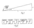
- FIGURE 1 shows the geometry to be used to derive a filter which will passively estimate range from target size and the change in target size with distance in the sensed scene to the target.
- x is a physical dimension of the target (e.g., width or height)
- r is the range along the LOS from the sensor to the target and ⁇ is the angle subtended by x in the sensor image
- the above is accomplished by providing a data base containing data capable of determining the particular type of target of interest being sensed within the scene being observed by the sensor.
- This data base also is provided with data for each type of target therein relating to target dimensions as a function of distance from the target. While the range estimator travels in a direction relative to the target the sensor continually observes the target and the system calculates the dimensions of the target and provides a range estimate therefrom. It follows that the system is fully passive and provides an entirely different approach to range estimation as compared with the prior art.
- FIGURE 2 there is shown a seeker in the form of a sensor depicted as a TV camera 1 which is moved relative to a target, such as by being placed on a movable vehicle such as, for example, an automobile for use in a collision avoidance system.
- the sensor creates a picture 3 of a scene being observed.
- the picture is provided in digital form, either directly or by conversion from analog to digital form with a converter 5.
- This provides an array of numbers representing the observed intensity at each of the pixels of the picture observed.
- the intensity can be, for example, the amount of light received or the amount of heat sensed in the case of an IR detector. These numbers are stored in a memory 7.
- a microprocessor 9 then reads these numbers in memory 7 and attempts to determine the size of the target of interest within the observed picture therefrom, this being a standard technique as discussed in W.K. Pratt, Digital Image Processing , John Wiley & Sons, 1978, pp. 471-550.
- This provides an instantaneous horizontal target dimension and an instantaneous vertical target dimension.
- This procedure and computation is continually repeated, such as, for example, thirty frames/second, while the distance between the target and the sensor simultaneously changes with the sensor generally traveling toward the target, though the invention herein merely requires known relative motion between target and sensor, preferably toward each other. With the sensor approaching the target, the target dimensions within the picture of the scene during each observation of the scene continue to increase with each successive observation.
- the initial range between the sensor and the target is computed from a data base containing data which recognizes the particular type of target (i.e., type of automobile, type of tank, etc.).
- the target type is known a priori, is recognized by a human operator, or is determined by an automatic target recognition (ATR) system such as described in "Automatic Target Recognition: State of the Art Survey", by B. Bhanu, IEEE Transactions on Aerospace and Electronic Systems , vol. AES-22, no. 4, July 1986, pp. 364-379.
- ATR automatic target recognition
- the system contains a data base as a part of the microprocessor circuitry which includes data relating to the size and/or other features of each of the types of targets which are expected to be encountered. Such data is provided relating to these targets for various ranges from the target to the sensor as discussed above and a rough estimated initial range to the target is initially provided to the system, though the range estimate need not be very accurate and can be in error by a factor of up to about an order of magnitude.
- the microprocessor 9 With the estimated range to the target entered, the microprocessor 9 with data base as discussed above, in conjunction with an extended Kalman filter therein, predicts the range to the target from the prior range estimate and adds the range traveled toward the target by the sensor, the first predicted range calculation using the estimated distance to the target set into the system.
- the extended Kalman filter estimates the size of the target and, for mathematical reasons, estimates the inverse of the range.
- the steps involved in making the range and target size predictions are:
- the remaining steps of the procedure involve standard extended Kalman filter equations as discussed in Estimation Theory with Applications to Communications and Control , by A.P. Sage and J.L. Melsa, McGraw-Hill, New York, 1971. These include a step of computing a residual and residual covariance wherein the size of the object in the picture is both predicted and measured with an error term being provided, along with the variance therebetween. The filter will then attempt to correct for the measured error by altering the estimate in a direction so as to correct the error. The intent is to drive the average error to zero to indicate that the system is predicting the size of the object correctly. When the size estimate is correct, this means that the range estimate is also correct at the same time.
- a step of adjusting the gain of the extended Kalman filter determines the weight to be given to the residual term to make the required corrections. This determines the speed at which the corrections are to be made, taking into account problems such as sensor noise.
- a step of state update and covariance takes the error term, multiplies it by some gains and adds the resulting corrections to the prior estimates of range and object size.
- the initial range estimate is computed from expected target dimensions and the initial target size as measured in the image.
- the initial state covariance matrix, P o is specified as: The (2,2) element of the matrix P o is computed using (see Introduction to the Theory of Statistics , by A.M. Mood, F.A. Graybill, and D.C. Boes, 3rd Ed., 1974, p. 181, equation 15).
- the extended Kalman filter defined herein is similar to the modified polar coordinate (MPC) filter described by Stallard in a previously cited reference. However, instead of relying upon LOS angles and LOS angle rates, this new filter uses target size.
- MPC modified polar coordinate
Landscapes
- Physics & Mathematics (AREA)
- Engineering & Computer Science (AREA)
- General Physics & Mathematics (AREA)
- Electromagnetism (AREA)
- Radar, Positioning & Navigation (AREA)
- Remote Sensing (AREA)
- Computer Vision & Pattern Recognition (AREA)
- Theoretical Computer Science (AREA)
- Radar Systems Or Details Thereof (AREA)
- Length Measuring Devices By Optical Means (AREA)
Abstract
Description
- This invention relates to passive estimation of range from a sensor or seeker to an object and, more specifically, to a system and method for estimating such range based upon the change of size of the object with change of distance of the object of interest within a scene from the sensor.
- There are a number of situations wherein it is desirable to estimate the range to an object of interest or target. For example, if for some reason the ILS of an aircraft becomes disabled, it is highly advantageous to know the distance from the entrance to the runway to the aircraft to assist in landing. In the case of automotive travel, it would be highly desirable to always be aware of the distance between vehicles to avoid collisions. An air-to-air missile can use estimated range to the target to determine when to detonate its warhead. Anti-tank missiles which fly non-line-of-sight trajectories use range to determine target position on the battlefield.
- Active techniques to measure range, such as radar, ladar and sonar, have been used extensively. The drawback of active ranging approaches, primarily in military applications, is that they can be easily detected by the target under attack. For example, if a submarine commander uses sonar to determine the position and velocity of an enemy ship, he runs a high risk of being detected. In such situations, it is advantageous to estimate range to the target passively.
- The most common technique used to passively estimate range to a target employs a Kalman filter to estimate range from angle-only measurements. Initially, a rectangular Cartesian coordinate-based extended Kalman filter (EKF) is used to estimate target positions and velocities in Cartesian coordinates from angle measurements. Analytical and experimental work has shown that the Cartesian-based EKF suffers from instabilities and bias in the filter as discussed in "Fundamental Properties and Performance of Bearings-Only Target Motion Analysis", by S.C. Nardone et al., IEEE Transactions on Auto. Control, Vol. AC-29, No. 4, Sept. 1984, pp. 775-781. A paper entitled "An Angle-Only Tracking Filter in Modified Spherical Coordinates", by D. V. Stallard, AIAA Guidance, Navigation, & Control Conference, Vol. 1, August 17-19, 1987, pp. 542-550 describes the use of modified spherical coordinates (MSC) which reduces problems with EKF observability, range bias and covariance ill-conditioning. In this paper, line-of-sight (LOS) angles of a missile are used as both filter measurements and states. This paper proposed the following six-state vector:

- Considering a command to LOS flight from a gunner to a target, the missile flies as closely as possible to the LOS of the gunner. Missile accelerations perpendicular to the LOS due to climbing, diving or yaw maneuvers are undesirable since such maneuvers may cause the missile to hit the ground or miss the target completely. However, since the angle-only measurement EKF approaches require maneuvers away from the LOS, these techniques cannot be used for LOS-only engagements.
- In accordance with the present invention, it has been determined that a sensor, such as a camera, IR detector, missile containing an imaging seeker or the like, using the size of the object or target and the size change of the object or target as seen within the sensed scene or picture over time as a guide as the distance between sensor and object changes, will provide an estimated range to the target. FIGURE 1 shows the geometry to be used to derive a filter which will passively estimate range from target size and the change in target size with distance in the sensed scene to the target. If x is a physical dimension of the target (e.g., width or height), r is the range along the LOS from the sensor to the target and Ψ is the angle subtended by x in the sensor image, then tan Ψ = x/r and d(tan Ψ)/dt = (ẋr - xṙ)/r2 = ẋ/r - (tan Ψ)(ṙ/r) and d(1/r)/dt = -(1/r)2ṙ. If the target is not changing aspect with respect to the missile, then ẋ = 0 and d(tan Ψ)/dt = - (tan Ψ)ṙ(1/r).
- Briefly, the above is accomplished by providing a data base containing data capable of determining the particular type of target of interest being sensed within the scene being observed by the sensor. This data base also is provided with data for each type of target therein relating to target dimensions as a function of distance from the target. While the range estimator travels in a direction relative to the target the sensor continually observes the target and the system calculates the dimensions of the target and provides a range estimate therefrom. It follows that the system is fully passive and provides an entirely different approach to range estimation as compared with the prior art.
-
- FIGURE 1 shows the geometry to be used to derive a filter which will passively estimate range from target size and the change in target size with distance to the target; and
- FIGURE 2 is a block diagram of a passive range estimation system in accordance with the present invention.
- Referring to FIGURE 2, there is shown a seeker in the form of a sensor depicted as a
TV camera 1 which is moved relative to a target, such as by being placed on a movable vehicle such as, for example, an automobile for use in a collision avoidance system. The sensor creates a picture 3 of a scene being observed. The picture is provided in digital form, either directly or by conversion from analog to digital form with aconverter 5. This provides an array of numbers representing the observed intensity at each of the pixels of the picture observed. The intensity can be, for example, the amount of light received or the amount of heat sensed in the case of an IR detector. These numbers are stored in a memory 7. A microprocessor 9 then reads these numbers in memory 7 and attempts to determine the size of the target of interest within the observed picture therefrom, this being a standard technique as discussed in W.K. Pratt, Digital Image Processing, John Wiley & Sons, 1978, pp. 471-550. This provides an instantaneous horizontal target dimension and an instantaneous vertical target dimension. This procedure and computation is continually repeated, such as, for example, thirty frames/second, while the distance between the target and the sensor simultaneously changes with the sensor generally traveling toward the target, though the invention herein merely requires known relative motion between target and sensor, preferably toward each other. With the sensor approaching the target, the target dimensions within the picture of the scene during each observation of the scene continue to increase with each successive observation. The initial range between the sensor and the target is computed from a data base containing data which recognizes the particular type of target (i.e., type of automobile, type of tank, etc.). Either the target type is known a priori, is recognized by a human operator, or is determined by an automatic target recognition (ATR) system such as described in "Automatic Target Recognition: State of the Art Survey", by B. Bhanu, IEEE Transactions on Aerospace and Electronic Systems, vol. AES-22, no. 4, July 1986, pp. 364-379. Once the target type is recognized, the average dimensions for the target type can be used to compute an initial range estimate. - Referring to FIGURE 1, with x being the average physical height or width of the target type, and with Xinit being the initial target height or width, respectively, as measured by the microprocessor 9 of FIGURE 2 within the first observed picture, if f is the seeker focal length, then the initial range estimate is computed as rinit=f(x/xinit).
- The system contains a data base as a part of the microprocessor circuitry which includes data relating to the size and/or other features of each of the types of targets which are expected to be encountered. Such data is provided relating to these targets for various ranges from the target to the sensor as discussed above and a rough estimated initial range to the target is initially provided to the system, though the range estimate need not be very accurate and can be in error by a factor of up to about an order of magnitude.
- With the estimated range to the target entered, the microprocessor 9 with data base as discussed above, in conjunction with an extended Kalman filter therein, predicts the range to the target from the prior range estimate and adds the range traveled toward the target by the sensor, the first predicted range calculation using the estimated distance to the target set into the system. The extended Kalman filter estimates the size of the target and, for mathematical reasons, estimates the inverse of the range. The steps involved in making the range and target size predictions are:
- a. Estimating the range to the object (target) at sensor frame k-1 which is 1/inverse range estimate at frame k-1.
- b. Determining the size of the object in physical dimensions (meters, feet, etc.) at frame k-1 from an estimate of tan Ψ at frame k-1 times the range estimate at frame k-1 in FIGURE 1.
- c. Estimating the range to the object at sensor frame k given frame k-1 which is the range estimate at frame k-1 plus the range traveled by the sensor between frames k-1 and k.
- d. Estimating the inverse range for frame k, given frame k-1 which is one divided by the range estimate for frame k, knowing frame k-1.
- e. Estimating the tanΨ of the object at frame k, knowing the tan Ψ at frame k-1, this tan at frame k being the size of the object in physical dimensions at frame k-1 times the inverse range estimate for frame k, given frame k-1.
- The remaining steps of the procedure involve standard extended Kalman filter equations as discussed in Estimation Theory with Applications to Communications and Control, by A.P. Sage and J.L. Melsa, McGraw-Hill, New York, 1971. These include a step of computing a residual and residual covariance wherein the size of the object in the picture is both predicted and measured with an error term being provided, along with the variance therebetween. The filter will then attempt to correct for the measured error by altering the estimate in a direction so as to correct the error. The intent is to drive the average error to zero to indicate that the system is predicting the size of the object correctly. When the size estimate is correct, this means that the range estimate is also correct at the same time. A step of adjusting the gain of the extended Kalman filter determines the weight to be given to the residual term to make the required corrections. This determines the speed at which the corrections are to be made, taking into account problems such as sensor noise. A step of state update and covariance takes the error term, multiplies it by some gains and adds the resulting corrections to the prior estimates of range and object size.
- Assuming the extended Kalman filter state vector at sensor frame k-1, xk-1, contains a first element (tan Ψ)k-1 and a second element (1/r)k-1, the extended Kalman filter equations setting forth the above are as follows:
- 1. State predictions:


- 2. State covariance predictions:


- 3. Residual and residual covariance:


- 4. Kalman gain:

- 5. State update and covariance:


- The initial state vector can be computed as x o = [tan(Ψo) (1/rinit)]T where Ψo is the initial target size measurement and rint is the initial range estimate. The initial range estimate is computed from expected target dimensions and the initial target size as measured in the image. The initial state covariance matrix, Po, is specified as:


- The extended Kalman filter defined herein is similar to the modified polar coordinate (MPC) filter described by Stallard in a previously cited reference. However, instead of relying upon LOS angles and LOS angle rates, this new filter uses target size.
- Though the invention has been described with respect to a specific preferred embodiment thereof, many variations and modifications will immediately become apparent to those skilled in the art. It is therefore the intention that the appended claims be interpreted as broadly as possible in view of the prior art to include all such variations and modifications.
Claims (8)
- A range estimation method which comprises the steps of:(a) providing a data base containing data for identification of certain targets and data for estimating the initial range to each of said certain targets as a function of the observed dimensions of said targets;(b) observing a scene containing a target a plurality of spaced apart times while moving relative to said target;(c) obtaining data from each observation of said scene relating to identification and dimensions of said target;(d) identifying said target from said data base; and(e) estimating the remaining range to said target from said data base and from a prior estimation of the remaining range to said target.
- The method of claim 1 wherein said step of observing comprises the step of providing a sensor for providing electrical signals representing the observed scene.
- The method of claim 2 wherein said sensor is one of a visible light or infrared sensor.
- The method of any preceding claim wherein said step of estimating comprises the steps providing the range travelled between successive observations of said scene, determining the change of dimensions bf said target in said scene and determining said remaining range to said target in response to said range travelled between successive observations of said scene and said change of dimensions of said target in said scene.
- A range estimation system which comprises:(a) a data base containing data for identification of certain targets and data for estimating the initial range to each of said certain targets as a function of the observed dimensions of said targets;(b) means for observing a scene containing a target a plurality of spaced apart times while said means for observing is moving relative to said target to provide data from each observation of said scene relating to identification and dimensions of said target; and(c) means to identify said target from said data base and estimate the remaining range to said target from said data base and from a prior estimation of the remaining range to said target.
- The system of claim 5 wherein said means for observing comprises a sensor for providing electrical signals representing the observed scene.
- The system of claim 6 wherein said sensor is one of a visible light or infrared sensor.
- The system of any one of claims 5 to 7 wherein said means to identify said target from said data base and estimate the remaining range comprises means to determine the range travelled between successive observations of said scene and computing means determining the change of dimensions of said target in said scene and determining said remaining range to said target in response to said range travelled between successive observations of said scene and said change of dimensions of said target in said scene.
Applications Claiming Priority (2)
| Application Number | Priority Date | Filing Date | Title |
|---|---|---|---|
| US2191396P | 1996-07-17 | 1996-07-17 | |
| US21913P | 1996-07-17 |
Publications (3)
| Publication Number | Publication Date |
|---|---|
| EP0820040A2 true EP0820040A2 (en) | 1998-01-21 |
| EP0820040A3 EP0820040A3 (en) | 1999-01-20 |
| EP0820040B1 EP0820040B1 (en) | 2004-08-18 |
Family
ID=21806812
Family Applications (1)
| Application Number | Title | Priority Date | Filing Date |
|---|---|---|---|
| EP97305333A Expired - Lifetime EP0820040B1 (en) | 1996-07-17 | 1997-07-17 | Passive range estimation using image size measurements |
Country Status (2)
| Country | Link |
|---|---|
| EP (1) | EP0820040B1 (en) |
| DE (1) | DE69730278T2 (en) |
Cited By (5)
| Publication number | Priority date | Publication date | Assignee | Title |
|---|---|---|---|---|
| GB2368118A (en) * | 2000-05-24 | 2002-04-24 | Daimler Chrysler Ag | Method of and device for detecting, ranging and classifying road users and obstacles |
| EP1876414A1 (en) | 2006-07-07 | 2008-01-09 | Honeywell International Inc. | Passive optical locator |
| US7453395B2 (en) | 2005-06-10 | 2008-11-18 | Honeywell International Inc. | Methods and systems using relative sensing to locate targets |
| WO2018023143A1 (en) * | 2016-08-03 | 2018-02-08 | Zkw Group Gmbh | Method and device for measuring a distance between a first vehicle and a second vehicle driving directly ahead of the first vehicle |
| WO2018146399A1 (en) * | 2017-02-10 | 2018-08-16 | Continental Automotive France | Method for processing images for the detection of an object along a route |
Families Citing this family (2)
| Publication number | Priority date | Publication date | Assignee | Title |
|---|---|---|---|---|
| DE102007025373B3 (en) * | 2007-05-31 | 2008-07-17 | Sick Ag | Visual monitoring device for use in e.g. automated guided vehicle system, has evaluation unit formed such that unit tests separation information based on another separation information of plausibility |
| DE102011075674A1 (en) * | 2011-05-11 | 2012-11-15 | Continental Teves Ag & Co. Ohg | Distance determination by means of a camera sensor |
Citations (3)
| Publication number | Priority date | Publication date | Assignee | Title |
|---|---|---|---|---|
| US5249128A (en) * | 1990-11-16 | 1993-09-28 | Texas Instruments Incorporated | System and method for determining the distance to an energy emitting object |
| US5282013A (en) * | 1992-06-26 | 1994-01-25 | Spar Aerospace Limited | Passive ranging technique for infrared search and track (IRST) systems |
| US5479360A (en) * | 1992-12-21 | 1995-12-26 | Martin Marietta Corporation | Target passive ranging without an ownship maneuver |
-
1997
- 1997-07-17 DE DE69730278T patent/DE69730278T2/en not_active Expired - Lifetime
- 1997-07-17 EP EP97305333A patent/EP0820040B1/en not_active Expired - Lifetime
Patent Citations (3)
| Publication number | Priority date | Publication date | Assignee | Title |
|---|---|---|---|---|
| US5249128A (en) * | 1990-11-16 | 1993-09-28 | Texas Instruments Incorporated | System and method for determining the distance to an energy emitting object |
| US5282013A (en) * | 1992-06-26 | 1994-01-25 | Spar Aerospace Limited | Passive ranging technique for infrared search and track (IRST) systems |
| US5479360A (en) * | 1992-12-21 | 1995-12-26 | Martin Marietta Corporation | Target passive ranging without an ownship maneuver |
Cited By (9)
| Publication number | Priority date | Publication date | Assignee | Title |
|---|---|---|---|---|
| GB2368118A (en) * | 2000-05-24 | 2002-04-24 | Daimler Chrysler Ag | Method of and device for detecting, ranging and classifying road users and obstacles |
| GB2368118B (en) * | 2000-05-24 | 2002-11-27 | Daimler Chrysler Ag | Method of and device for detecting ranging and classifying road users and obstacles |
| US6838980B2 (en) | 2000-05-24 | 2005-01-04 | Daimlerchrysler Ag | Camera-based precrash detection system |
| US7453395B2 (en) | 2005-06-10 | 2008-11-18 | Honeywell International Inc. | Methods and systems using relative sensing to locate targets |
| US7518713B2 (en) | 2005-11-08 | 2009-04-14 | Honeywell International Inc. | Passive-optical locator |
| EP1876414A1 (en) | 2006-07-07 | 2008-01-09 | Honeywell International Inc. | Passive optical locator |
| WO2018023143A1 (en) * | 2016-08-03 | 2018-02-08 | Zkw Group Gmbh | Method and device for measuring a distance between a first vehicle and a second vehicle driving directly ahead of the first vehicle |
| WO2018146399A1 (en) * | 2017-02-10 | 2018-08-16 | Continental Automotive France | Method for processing images for the detection of an object along a route |
| FR3062943A1 (en) * | 2017-02-10 | 2018-08-17 | Continental Automotive France | METHOD OF PROCESSING IMAGES FOR DETECTION OF AN OBJECT ALONG A ROAD |
Also Published As
| Publication number | Publication date |
|---|---|
| DE69730278D1 (en) | 2004-09-23 |
| EP0820040A3 (en) | 1999-01-20 |
| EP0820040B1 (en) | 2004-08-18 |
| DE69730278T2 (en) | 2005-08-11 |
Similar Documents
| Publication | Publication Date | Title |
|---|---|---|
| US5867256A (en) | Passive range estimation using image size measurements | |
| EP2159779B1 (en) | Using image sensor and tracking filter time-to-go to avoid mid-air collisions | |
| US20170059692A1 (en) | Mitigation of Small Unmanned Aircraft Systems Threats | |
| US6639553B2 (en) | Passive/ranging/tracking processing method for collision avoidance guidance | |
| US8798812B2 (en) | Three-dimensional digital map | |
| EP1610152B1 (en) | Tracking of a moving object for a self-defence system | |
| US20070073473A1 (en) | System and method of target tracking using sensor fusion | |
| EP3004786B1 (en) | Method of fire control for gun-based anti-aircraft defence | |
| EP0820040B1 (en) | Passive range estimation using image size measurements | |
| US9384669B2 (en) | Method and arrangement for estimating at least one parameter of an intruder | |
| EP0530050B1 (en) | Method and apparatus for tracking an aimpoint on an elongate structure | |
| RU2728197C1 (en) | Method to control a group of unmanned aerial vehicles taking into account the degree of danger of surrounding objects | |
| Lee et al. | See and avoidance behaviors for autonomous navigation | |
| US5373318A (en) | Apparent size passive range method | |
| RU2308093C1 (en) | Method of control of flying vehicles in heading by means of two-position radar system | |
| EP0530049B1 (en) | Method and apparatus for tracking an aimpoint with arbitrary subimages | |
| RU2498342C1 (en) | Method of intercepting aerial targets with aircraft | |
| Lee et al. | Performance Verification of a Target Tracking System With a Laser Rangefinder | |
| GB2279444A (en) | Missile guidance system | |
| Forlenza | Vision based strategies for implementing Sense and Avoid capabilities onboard Unmanned Aerial Systems | |
| Saini et al. | Air-to-air tracking performance with inertial navigation and gimballed radar: a kinematic scenario | |
| RU2819590C1 (en) | Onboard intelligent uav search and guidance system | |
| Gunasinghe et al. | A mid-air collision warning system: Vision-based estimation of collision threats for aircraft | |
| Aboutalib et al. | All source adaptive fusion for aided navigation in non-GPS environment | |
| RU2795367C1 (en) | Method of software adjustable target support |
Legal Events
| Date | Code | Title | Description |
|---|---|---|---|
| PUAI | Public reference made under article 153(3) epc to a published international application that has entered the european phase |
Free format text: ORIGINAL CODE: 0009012 |
|
| AK | Designated contracting states |
Kind code of ref document: A2 Designated state(s): DE FR GB IT NL |
|
| AX | Request for extension of the european patent |
Free format text: AL;LT;LV;RO;SI |
|
| PUAL | Search report despatched |
Free format text: ORIGINAL CODE: 0009013 |
|
| AK | Designated contracting states |
Kind code of ref document: A3 Designated state(s): AT BE CH DE DK ES FI FR GB GR IE IT LI LU MC NL PT SE |
|
| AX | Request for extension of the european patent |
Free format text: AL;LT;LV;RO;SI |
|
| RHK1 | Main classification (correction) |
Ipc: G01S 11/12 |
|
| RAP1 | Party data changed (applicant data changed or rights of an application transferred) |
Owner name: RAYTHEON COMPANY |
|
| 17P | Request for examination filed |
Effective date: 19990719 |
|
| AKX | Designation fees paid |
Free format text: DE FR GB IT NL |
|
| 17Q | First examination report despatched |
Effective date: 20021105 |
|
| GRAP | Despatch of communication of intention to grant a patent |
Free format text: ORIGINAL CODE: EPIDOSNIGR1 |
|
| RAP1 | Party data changed (applicant data changed or rights of an application transferred) |
Owner name: RAYTHEON COMPANY |
|
| GRAS | Grant fee paid |
Free format text: ORIGINAL CODE: EPIDOSNIGR3 |
|
| GRAA | (expected) grant |
Free format text: ORIGINAL CODE: 0009210 |
|
| AK | Designated contracting states |
Kind code of ref document: B1 Designated state(s): DE FR GB IT NL |
|
| PG25 | Lapsed in a contracting state [announced via postgrant information from national office to epo] |
Ref country code: NL Free format text: LAPSE BECAUSE OF FAILURE TO SUBMIT A TRANSLATION OF THE DESCRIPTION OR TO PAY THE FEE WITHIN THE PRESCRIBED TIME-LIMIT Effective date: 20040818 Ref country code: IT Free format text: LAPSE BECAUSE OF FAILURE TO SUBMIT A TRANSLATION OF THE DESCRIPTION OR TO PAY THE FEE WITHIN THE PRE;WARNING: LAPSES OF ITALIAN PATENTS WITH EFFECTIVE DATE BEFORE 2007 MAY HAVE OCCURRED AT ANY TIME BEFORE 2007. THE CORRECT EFFECTIVE DATE MAY BE DIFFERENT FROM THE ONE RECORDED.SCRIBED TIME-LIMIT Effective date: 20040818 |
|
| REG | Reference to a national code |
Ref country code: GB Ref legal event code: FG4D |
|
| REF | Corresponds to: |
Ref document number: 69730278 Country of ref document: DE Date of ref document: 20040923 Kind code of ref document: P |
|
| NLV1 | Nl: lapsed or annulled due to failure to fulfill the requirements of art. 29p and 29m of the patents act | ||
| PLBE | No opposition filed within time limit |
Free format text: ORIGINAL CODE: 0009261 |
|
| STAA | Information on the status of an ep patent application or granted ep patent |
Free format text: STATUS: NO OPPOSITION FILED WITHIN TIME LIMIT |
|
| ET | Fr: translation filed | ||
| 26N | No opposition filed |
Effective date: 20050519 |
|
| PGFP | Annual fee paid to national office [announced via postgrant information from national office to epo] |
Ref country code: GB Payment date: 20120711 Year of fee payment: 16 |
|
| PGFP | Annual fee paid to national office [announced via postgrant information from national office to epo] |
Ref country code: DE Payment date: 20120711 Year of fee payment: 16 Ref country code: FR Payment date: 20120719 Year of fee payment: 16 |
|
| GBPC | Gb: european patent ceased through non-payment of renewal fee |
Effective date: 20130717 |
|
| REG | Reference to a national code |
Ref country code: FR Ref legal event code: ST Effective date: 20140331 |
|
| PG25 | Lapsed in a contracting state [announced via postgrant information from national office to epo] |
Ref country code: DE Free format text: LAPSE BECAUSE OF NON-PAYMENT OF DUE FEES Effective date: 20140201 Ref country code: GB Free format text: LAPSE BECAUSE OF NON-PAYMENT OF DUE FEES Effective date: 20130717 |
|
| REG | Reference to a national code |
Ref country code: DE Ref legal event code: R119 Ref document number: 69730278 Country of ref document: DE Effective date: 20140201 |
|
| PG25 | Lapsed in a contracting state [announced via postgrant information from national office to epo] |
Ref country code: FR Free format text: LAPSE BECAUSE OF NON-PAYMENT OF DUE FEES Effective date: 20130731 |