EP0818756A2 - Method and device for non-contact detecting the presence of a person at different control stations - Google Patents
Method and device for non-contact detecting the presence of a person at different control stations Download PDFInfo
- Publication number
- EP0818756A2 EP0818756A2 EP97110213A EP97110213A EP0818756A2 EP 0818756 A2 EP0818756 A2 EP 0818756A2 EP 97110213 A EP97110213 A EP 97110213A EP 97110213 A EP97110213 A EP 97110213A EP 0818756 A2 EP0818756 A2 EP 0818756A2
- Authority
- EP
- European Patent Office
- Prior art keywords
- receiving body
- base station
- data carrier
- guide device
- shaped
- Prior art date
- Legal status (The legal status is an assumption and is not a legal conclusion. Google has not performed a legal analysis and makes no representation as to the accuracy of the status listed.)
- Withdrawn
Links
Images
Classifications
-
- G—PHYSICS
- G07—CHECKING-DEVICES
- G07C—TIME OR ATTENDANCE REGISTERS; REGISTERING OR INDICATING THE WORKING OF MACHINES; GENERATING RANDOM NUMBERS; VOTING OR LOTTERY APPARATUS; ARRANGEMENTS, SYSTEMS OR APPARATUS FOR CHECKING NOT PROVIDED FOR ELSEWHERE
- G07C1/00—Registering, indicating or recording the time of events or elapsed time, e.g. time-recorders for work people
- G07C1/22—Registering, indicating or recording the time of events or elapsed time, e.g. time-recorders for work people in connection with sports or games
- G07C1/24—Race time-recorders
-
- G—PHYSICS
- G07—CHECKING-DEVICES
- G07C—TIME OR ATTENDANCE REGISTERS; REGISTERING OR INDICATING THE WORKING OF MACHINES; GENERATING RANDOM NUMBERS; VOTING OR LOTTERY APPARATUS; ARRANGEMENTS, SYSTEMS OR APPARATUS FOR CHECKING NOT PROVIDED FOR ELSEWHERE
- G07C1/00—Registering, indicating or recording the time of events or elapsed time, e.g. time-recorders for work people
- G07C1/20—Checking timed patrols, e.g. of watchman
Definitions
- the invention relates to a method and a device for contactless detection of presence a person at different control posts.
- the invention can be advantageous in orienteering be used.
- non-volatile data memories that can be read and, if necessary, written in contactless fashion is known in the sports sector.
- Such arrangements are described, for example, in the patent specifications WO 93/13500 and DE 44 43 402 A1, the common feature of the known solutions being that the base stations necessarily have telecontrol devices for data acquisition.
- the disadvantage of this method is the absence a signaling device assigned to the control post, the data exchange to the competitor. Furthermore it is not possible to get information about at the checkpoint to record the competitors passing the post, to process, save or via other Additional devices to a data collection point transfer.
- the invention has for its object a device and a method for contactless Proof of location and time of people at control posts specify where the competitor does not additional readout and verification device to be carried needed.
- control post Base station can be created, the one directly on Compass placed proof carrier clearly mutually identified and about technical possibilities for signaling, storage and remote transmission of the exchanged data.
- the object is achieved by a method resolved, at which every control body except the Code is assigned a programmable timer and the code and time using a magnetic Field assigned to a person Data carriers are transferred, the code and the time in the disk in a non-volatile Memory can be saved.
- An advantageous embodiment of the method stipulates that the time of one at the checkpoint attached base station on the Transfer data carrier and there directly addressed storage space, that of the unique Coding corresponds to the respective base station, is filed.
- the device provides that - The disk has a non-volatile memory has and at a defined point within a receiving body is arranged and that a base station assigned to the control point a guide device for the introduction of the receiving body has a defined location of the inserted receiving body opposite the guide device guaranteed.
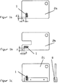
- a miniaturized, non-volatile, read and writable disk 1 is in a defined Position attached to the receiving body 2. To do this the plate-shaped receiving body 2a, 2b and 2c over at least one right-angled outer boundary, from which the data carrier 1 at a distance is located remotely. It is beneficial to continue a layer height h of the data carrier 1 within to comply with the receiving body 2.
- the thickness of the disk-shaped receiving body 2 corresponds at least the corresponding height of the data carrier 1, so that when integrating the data carrier 1 in the receiving body 2, the outer shape of the receiving body is not changed.
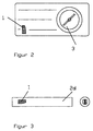
- Figure 2 shows a particularly advantageous embodiment the arrangement according to the invention, in which the base plate of a compass 3 as a receiving body of disk 1 is used.
- Figures 1b, 1c and 3 show receiving bodies that especially for base stations with special Guide devices are suitable. Of the Receiving body 2c in Figure 1c is attached to a Guide device 5b adapted in Figure 6. Of the Receiving body 2b in Figure 1b and the rod-shaped Receiving bodies 2d in FIG. 3 are not for explained guide devices with circular or pipe-like entries can be used.
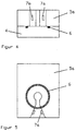
- Figures 4 and 5 explain the application of Data exchange device according to the invention between the data carrier 1 and the base station 4.
- the base station 4 has a guide device 5a with a wedge-shaped recess and a hole that will ensure that when placed of the receiving body 2 with disk 1 in the Guide device 5a a partially determined positive guidance so that the magnetic axis of the Data carrier 1 secure coupling with the magnetic axis of a coupling coil 6 Base station 4 enables. To do this covers the Coupling coil 6 the entire surface of the wedge-shaped Cutout and the bore of the guide device 5a, in which the receiving body 2 with data carrier 1 can be placed.
- the design of the wedge-shaped recess of the guide device 5a allows the placement of exactly one Receiving body 2 on the base station 4.
- Die Wall thickness of the guide device 5 is selected so that an outside of the wedge-shaped recess and Data media placed outside the hole 1 cannot exchange data with the base station.
- optical Signaling devices 7 arranged over Operating states of the base station 4 and required data exchange between data carriers 1 and base station 4.
- the light exit surfaces of the optical signal devices 7a and 7b are in the interior of the wedge-shaped Recess of the guide device 5a to largely prevent disturbing extraneous light influences.
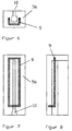
- Figures 6, 7 and 8 show one at the base station 4 attached to the device according to the invention Guide device 5b for insertion and Fixing the position of the receiving body 2c.
- the guide device 5b has a receiving slot 10, which is designed so that the receiving body 2c along a limited trajectory is carried out in a predetermined position, so that the data carrier 1 of the receiving body 2c is safe in the magnetic field in a guide device 5b attached and enclosing the guide slot 10 Form coil 11 is moved.
- Figure 6 shows a web-shaped guide device in front view
- Figure 7 the associated top view
- FIG. 8 the associated side view.
- the method for using the device for location and time detection according to the invention enables a competition-specific initialization of the data carrier assigned to the competitor before the start of the competition.
- Information about the name of the competitor, club, competition class and start time can be stored directly or in encrypted form on data carrier 1 using a start number.
- the competition by placing the data carrier 1 within the area provided in the base station 4, the current competition or time is transferred from the base station to the data carrier.
- each base station can be directly assigned a storage space in the data carrier which corresponds, for example, to a code number that is visually displayed on the base station.
- the data exchange between base station 4 and data carrier 1 can be visually recognized by the competitor by means of the signaling device 7a and 7b attached in the guide device 5a.
- access to the data carrier can be protected with a competition-specific password. If the time of the data exchange is written directly to a memory location corresponding to the coding of the base station, the most recent process is saved.
- a data record consisting of the control code and the associated time is stored continuously. For this purpose, a memory location of the subsequent data record is incremented with each identification process. With this embodiment, the complete course of the competition of the respective athlete is clearly mapped.
- a result expression can have the following form: Surname class route Scoring Lion H21 7.4 km Item required 31-45 -...- 94-70-99 OK Leo 13 items -Additional item 27 190 m -Posts - Total runtime 3:12 7:20 13:14 19:59 -Time difference 3:12 4:08 5:54 6:45 -Running speed 6.0 km / h Panther H40 5.6 km - Item required 32-45 -...- 67-71-99 OK Peter 11 items -Additional items 130 m -Posts -Total runtime -Time difference -Runtime speed
- the optical display elements 7a and 7b are activated in the following way: Starting base station red green a Disk in the field out a a Start time has been reached out out Disk removed from the field
- the start time is checked with Signaling of the start release, in the finish the acquisition the total running time and reading the im Disk 1 saved during the competition Information.
- no competition-specific initialization of the Card before the start of the competition Immediately before Start will be an appropriately configured base station 4 a unique one assigned to the data carrier ID number in that of the competition-specific Copied memory locations assigned to the start number.
- the competition-specific assignment is made Starting number for card number when reading out that in disk 1 during the competition stored information.
- the use of the arrangement according to the invention and the procedure for contactless local and Proof of time will be made by your competitor assignable registration device to be assigned superfluous.
- the integration of the Disk 1 in the competitor always carried compass reduces the number of to be carried independently of one another in the competition technical aids and evidence.
- the stake a base station 4 designed according to the invention enables the use of a competitor assigned disk 1, the practical is maintenance-free and independent of age. Of the Process of data exchange between base station 4 and disk 1 is within a constant Duration guaranteed. Thus are for all competition participants same conditions with no differences given in the quality of the verification codes.
Landscapes
- Physics & Mathematics (AREA)
- General Physics & Mathematics (AREA)
- Time Recorders, Dirve Recorders, Access Control (AREA)
- Management, Administration, Business Operations System, And Electronic Commerce (AREA)
- Near-Field Transmission Systems (AREA)
Abstract
Description
Die Erfindung betrifft ein Verfahren und eine Vorrichtung zum berührungslosen Erfassen der Anwesenheit einer Person an verschiedenen Kontrollstellen.The invention relates to a method and a device for contactless detection of presence a person at different control posts.
Die Erfindung kann vorteilhaft beim Orientierungslauf eingesetzt werden.The invention can be advantageous in orienteering be used.
In der Sportart Orientierungslauf sind durch den Wettkämpfer eine Anzahl von vorgegebenen Kontrollposten vollständig und in einer vorgegebenen Reihenfolge anzulaufen. Jeder Wettkämpfer führt ein ihm zugeordnetes Nachweisgerät mit sich, auf das von einer an jedem Kontrollposten angebrachten Einrichtung ein jedem Kontrollposten zugeordneter Code übertragen wird.In the sport orienteering are through the Competitors a number of predetermined checkpoints completely and in a given Order to start. Every competitor introduces associated with him, on the from a facility attached to each checkpoint a code assigned to each control post is transmitted.
Andere Einsatzfälle der erfindungsgemäßen Einrichtung sind denkbar, z.B. zum Nachweis von vorgeschriebenen Rundgängen des Wachpersonals in zu bewachenden Objekten.Other applications of the device according to the invention are conceivable, e.g. as proof of prescribed Tours of the guards to be guarded Objects.
Der Einsatz von kontaktlos les- und gegebenenfalls
schreibbaren nichtflüchtigen Datenspeichern im
Sportbereich ist bekannt. Es existieren z.B. Anwendungen,
in denen kontaktlos über bestimmte Entfernungen
Informationen aus unterschiedlich ausgebildeten
Basisstationen und in den Sportlern zugeordneten
Datenspeichern vorrangig zur Erfassung von
Zwischen- und Endzeiten ausgelesen werden.
Solche Anordnungen sind beispielsweise in den
Patentschriften WO 93/13500 und DE 44 43 402 A1
beschrieben, wobei gemeinsames Merkmal der bekannten
Lösungen ist, daß die Basisstationen notwendigerweise
über Fernwirkeinrichtungen zur Datenerfassung
verfügen.The use of non-volatile data memories that can be read and, if necessary, written in contactless fashion is known in the sports sector. There are, for example, applications in which information is read contactlessly over certain distances from base stations of different designs and in data stores assigned to the athletes, primarily for recording intermediate and end times.
Such arrangements are described, for example, in the patent specifications WO 93/13500 and DE 44 43 402 A1, the common feature of the known solutions being that the base stations necessarily have telecontrol devices for data acquisition.
Im Stand der Technik ist auch bekannt, kontaktlos auslesbare Codeträger zu verwenden, die an einer geeigneten Stelle am Kontrollposten befestigt werden. Jeder innerhalb eines Wettkampfes verwendete Codeträger besitzt eine eindeutige Codierung. Zum Nachweis des Anlaufens der geforderten Kontrollposten verwendet jeder Wettkämpfer ein Auslesegerät, das bis zur Auswertung des Wettkampfes die ausgelesenen Kontrollcodes und die Reihenfolge des Anlaufens erfaßt und zusätzlich zum Kontrollcode die zugehörige Zeit speichert.Contactless is also known in the prior art to use readable code carriers on a appropriate place on the checkpoint. Everyone used within a competition Code carrier has a unique coding. To the Evidence of the start of the required checkpoints each competitor uses a reader, that until the evaluation of the competition read control codes and the order of the Start-up recorded and in addition to the control code saves the associated time.
Nachteilig bei diesem Verfahren ist das Fehlen einer dem Kontrollposten zugeordneten Signalisierungseinrichtung, die einen erfolgten Datenaustausch dem Wettkämpfer anzeigt. Weiterhin ist es nicht möglich, am Kontrollposten Informationen über die den Posten passierenden Wettkämpfer zu erfassen, zu verarbeiten, zu speichern oder über weitere Zusatzeinrichtungen an eine Datensammelstelle zu übertragen. Das dem Wettkämpfer zugeordnete und von ihm im Wettkampf mitzuführende Auslesegerät ist technisch aufwendig. Es benötigt einen Energiespeicher und ist deshalb nicht wartungsfrei. Nachteilig ist ferner seine für den Wettkämpfer störende Größe.The disadvantage of this method is the absence a signaling device assigned to the control post, the data exchange to the competitor. Furthermore it is not possible to get information about at the checkpoint to record the competitors passing the post, to process, save or via other Additional devices to a data collection point transfer. The one assigned to the competitor and by reading device to be carried in the competition technically complex. It needs an energy store and is therefore not maintenance-free. Disadvantageous is also his for the competitor disturbing size.
Der Erfindung liegt die Aufgabe zugrunde, eine Vorrichtung und ein Verfahren zum berührungslosen Orts- und Zeitnachweis von Personen an Kontrollstellen anzugeben, bei dem der Wettkämpfer kein mitzuführendes zusätzliches Auslese- und Nachweisgerät benötigt.The invention has for its object a device and a method for contactless Proof of location and time of people at control posts specify where the competitor does not additional readout and verification device to be carried needed.
Ferner soll eine dem Kontrollposten zugeordnete Basisstation geschaffen werden, die einen direkt am Kompaß plazierten Nachweisträger eindeutig wechselseitig identifiziert und über technische Möglichkeiten zur Signalisierung, Speicherung und Fernübertragung der ausgetauschten Daten verfügt.Furthermore, one should be assigned to the control post Base station can be created, the one directly on Compass placed proof carrier clearly mutually identified and about technical possibilities for signaling, storage and remote transmission of the exchanged data.
Erfindungsgemäß wird die Aufgabe durch ein Verfahren gelöst, bei dem jeder Kontrollstelle außer dem Code ein programmierbarer Zeitgeber zugeordnet ist und der Code und die Uhrzeit mittels eines magnetischen Feldes auf einen der Person zugeordneten Datenträger übertragen werden, wobei der Code und die Uhrzeit im Datenträger in einem nichtflüchtigen Speicher gespeichert werden.According to the invention, the object is achieved by a method resolved, at which every control body except the Code is assigned a programmable timer and the code and time using a magnetic Field assigned to a person Data carriers are transferred, the code and the time in the disk in a non-volatile Memory can be saved.
Eine vorteilhafte Ausgestaltung des Verfahrens sieht vor, daß die Uhrzeit von einer an der Kontrollstelle angebrachten Basisstation auf den Datenträger übertragen und dort auf einem direkt adressierten Speicherplatz, der der eindeutigen Codierung der jeweiligen Basisstation entspricht, abgelegt wird.An advantageous embodiment of the method stipulates that the time of one at the checkpoint attached base station on the Transfer data carrier and there directly addressed storage space, that of the unique Coding corresponds to the respective base station, is filed.
Die erfindungsgemäße Vorrichtung sieht vor, daß - der Datenträger einen nichtflüchtigen Speicher aufweist und an einer definierten Stelle innerhalb eines Aufnahmekörpers angeordnet ist und daß eine der Kontrollstelle zugeordnete Basisstation eine Führungsvorrichtung zur Einführung des Aufnahmekörpers aufweist, die eine definierte Lage des eingeführten Aufnahmekörpers gegenüber der Führungsvorrichtung gewährleistet.The device according to the invention provides that - The disk has a non-volatile memory has and at a defined point within a receiving body is arranged and that a base station assigned to the control point a guide device for the introduction of the receiving body has a defined location of the inserted receiving body opposite the guide device guaranteed.
Vorteilhafte Ausgestaltungen der erfindungsgemäßen Vorrichtung sind in den Ansprüchen 5 bis 16 angegeben.Advantageous embodiments of the invention Device are specified in claims 5 to 16.
Durch den Einsatz eines Transponders mit einem Datenspeicher, der durch die von einer Basisstation ausgesendeten und im Transponder gespeicherten Daten den Nachweis für die Erfüllung der vorgegebenen Aufgaben erbringt und dessen zweckmäßige Integration in vorhandene oder zu schaffende Vorrichtungen, wird eine zweckmäßige Handhabbarkeit gewährleistet.By using a transponder with a Data storage by that of a base station transmitted and stored in the transponder Data proof of compliance with the given Performs tasks and their appropriate Integration into existing or to be created devices, becomes a convenient manageability guaranteed.
Die Erfindung wird nachfolgend an Ausführungsbeispielen
näher erläutert. In den zugehörigen
Zeichnungen zeigen:
und
and
Ein miniaturisierter, nichtflüchtiger, les- und
beschreibbarer Datenträger 1 ist in einer definierten
Lage am Aufnahmekörper 2 angebracht. Dazu verfügen
die plattenförmigen Aufnahmekörper 2a, 2b und
2c über mindestens eine rechtwinklige Außenbegrenzung,
von welcher der Datenträger 1 im Abstand a
entfernt angeordnet ist. Es ist vorteilhaft, weiterhin
eine Lagehöhe h des Datenträgers 1 innerhalb
des Aufnahmekörpers 2 einzuhalten. Die Dicke des
scheibenförmigen Aufnahmekörpers 2 entspricht mindestens
der entsprechenden Bauhöhe des Datenträgers
1, so daß bei einer Integration des Datenträgers 1
in den Aufnahmekörper 2 die äußere Form des Aufnahmekörpers
nicht verändert wird.A miniaturized, non-volatile, read and
Figur 2 zeigt eine besonders vorteilhafte Ausgestaltung
der erfindungsgemäßen Anordnung, bei der
die Grundplatte eines Kompasses 3 als Aufnahmekörper
des Datenträgers 1 verwendet wird.Figure 2 shows a particularly advantageous embodiment
the arrangement according to the invention, in which
the base plate of a
Die Figuren 1b, 1c und 3 zeigen Aufnahmekörper, die
insbesonders für Basisstationen mit speziellen
Führungsvorrichtungen geeignet sind. Der
Aufnahmekörper 2c in Figur 1c ist an eine
Führungsvorrichtung 5b in Figur 6 angepaßt. Der
Aufnahmekörper 2b in Figur 1b und der stabförmige
Aufnahmekörper 2d in Figur 3 sind für nicht näher
erläuterte Führungsvorrichtungen mit kreisförmigen
oder rohrähnlichen Einführungen verwendbar.Figures 1b, 1c and 3 show receiving bodies that
especially for base stations with special
Guide devices are suitable. Of the
Receiving
Die Figuren 4 und 5 erläutern die Anwendung der
erfindungsgemäßen Vorrichtung zum Datenaustausch
zwischen dem Datenträger 1 und der Basisstation 4.
Dazu besitzt die Basisstation 4 eine Führungsvorrichtung
5a mit einer keilförmigen Aussparung und
einer Bohrung, die gewährleisten, daß bei Plazierung
des Aufnahmekörpers 2 mit Datenträger 1 in der
Führungsvorrichtung 5a eine teilbestimmte Zwangsführung
so erfolgt, daß die magnetische Achse des
Datenträgers 1 eine sichere Kopplung mit der
magnetischen Achse einer Koppelspule 6 der
Basisstation 4 ermöglicht. Dazu überdeckt die
Koppelspule 6 die gesamte Fläche des keilförmigen
Ausschnitts und der Bohrung der Führungsvorrichtung
5a, in dem der Aufnahmekörper 2 mit Datenträger 1
plaziert werden kann. Die Gestaltung der
keilförmigen Aussparung der Führungsvorrichtung 5a
ermöglicht die Plazierung genau eines
Aufnahmekörpers 2 auf der Basisstation 4. Die
Wanddicke der Führungsvorrichtung 5 ist so gewählt,
daß ein außerhalb der keilförmigen Aussparung und
außerhalb der Bohrung plazierter Datenträger 1
keine Daten mit der Basisstation austauschen kann.
Innerhalb der Führungsvorrichtung 5a sind optische
Signaleinrichtungen 7 angeordnet, die über
Betriebszustände der Basisstation 4 und den
erforderlichen Datenaustausch zwischen Datenträger
1 und Basisstation 4 informieren. Die Lichtaustrittsflächen
der optischen Signaleinrichtungen 7a
und 7b befinden sich im Innenbereich der keilförmigen
Aussparung der Führungsvorrichtung 5a, um
störende Fremdlichteinflüsse weitgehend zu unterbinden.Figures 4 and 5 explain the application of
Data exchange device according to the invention
between the
Die Figuren 6, 7 und 8 zeigen eine an die Basisstation
4 der erfindungsgemäßen Vorrichtung angebrachte
Führungsvorrichtung 5b zur Einführung und
Lagefixierung des Aufnahmekörpers 2c.
Die Führungsvorrichtung 5b besitzt einen Aufnahmeschlitz
10, der so ausgebildet ist, daß der Aufnahmekörper
2c entlang einer begrenzten Bewegungsbahn
in einer vorgegebenen Lage geführt wird, so
daß der Datenträger 1 des Aufnahmekörpers 2c sicher
im Magnetfeld einer in der Führungsvorrichtung 5b
angebrachten und den Führungsschlitz 10 umschließenden
Formspule 11 bewegt wird. Figures 6, 7 and 8 show one at the
Figur 6 zeigt eine bahnförmige Führungsvorrichtung in Vorderansicht, Figur 7 die zugehörige Draufsicht und Figur 8 die zugehörige Seitenansicht.Figure 6 shows a web-shaped guide device in front view, Figure 7, the associated top view and FIG. 8 the associated side view.
Das Verfahren zur Nutzung der erfindungsgemäßen
Vorrichtung zum Orts- und Zeitnachweis ermöglicht
eine wettkampfspezifische Initialisierung des dem
Wettkämpfer zugeordneten Datenträgers vor Wettkampfbeginn.
Informationen über Namen des Wettkämpfers,
Verein, Wettkampfklasse und Startzeit
können direkt oder verschlüsselt über eine Startnummer
in den Datenträger 1 eingespeichert werden.
Während des Wettkampfes erfolgt durch Plazierung
des Datenträgers 1 innerhalb des in der Basisstation
4 vorgesehenen Bereiches die Übertragung der
aktuellen Wettkampf- oder Uhrzeit von der Basisstation
in den Datenträger. Dazu kann jeder Basisstation
direkt ein Speicherplatz im Datenträger zugeordnet
werden, der beispielsweise einer auf der
Basisstation optisch sichtbar aufgebrachten Codezahl
entspricht. Der Datenaustausch zwischen
Basisstation 4 und Datenträger 1 kann durch den
Wettkämpfer mittels der in der Führungsvorrichtung
5a angebrachten Signalisierungseinrichtung 7a und
7b visuell erkannt werden. Bei zwei
Signalisierungseinrichtungen, denen vorteilhaft die
Farben rot und grün zugeordnet werden können, ist
folgendes Schema zweckmäßig:
Zur Erhöhung der Sicherheit gegenüber unzulässigen
Manipulationen kann der Zugriff auf den Datenträger
mit einein wettkampfspezifischen Passwort geschützt
werden. Wird der Zeitpunkt des Datenaustausches
direkt auf einen der Kodierung der Basisstation
entsprechenden Speicherplatz geschrieben, so wird
der jeweils letzte Vorgang gespeichert.
In einem weiteren Ausführungsbeispiel des erfindungsgemäßen
Verfahrens erfolgt das Abspeichern
eines Datensatzes bestehend aus dem Kontrollcode
und der zugehörigen Zeit fortlaufend. Dazu wird ein
Speicherplatz des jeweils nachfolgenden Datensatzes
bei jedem Identifikationsvorgang inkrementiert. Mit
dieser Ausführungsform wird der vollständige Wettkampfverlauf
des jeweiligen Sportlers eindeutig
abgebildet. To increase security against unauthorized manipulation, access to the data carrier can be protected with a competition-specific password. If the time of the data exchange is written directly to a memory location corresponding to the coding of the base station, the most recent process is saved.
In a further exemplary embodiment of the method according to the invention, a data record consisting of the control code and the associated time is stored continuously. For this purpose, a memory location of the subsequent data record is incremented with each identification process. With this embodiment, the complete course of the competition of the respective athlete is clearly mapped.
Während des Datenaustausches zwischen Basisstation
und Datenträger können wettkampftypische Informationen
aus dem Datenträger ausgelesen und zusammen
mit der Uhrzeit in der Basisstation gespeichert und
befehlsgesteuert innerhalb des Wettkampfes über
Fernwirkeinrichtung ausgelesen oder nach Wettkampfende
direkt in ein Auswertegerät übertragen
werden. Diese Möglichkeit der doppelten Identifizierung
erhöht die Transparenz des Wettkampfes und
dessen Sicherheit.
Nach Durchlaufen der Ziellinie erfolgt das Auslesen
des Datenträgers. Durch die Möglichkeit einer rechnergestützten
online-Auswertung sind eine sofortige
Kontrolle und ein sofortiger Ergebnisausdruck mit
erweiterten Informationen realisierbar. Diese
Informationen umfassen:
- Nachweis des Anlaufens geforderter Kontrollpunkte
- Nachweis des Anlaufens der geforderten Kontrollpunkte in einer vorgegebenen Reihenfolge
- Informationen über das Anlaufen nicht geforderter Kontrollpunkte
- Informationen über Teil- und Zwischenlaufzeiten
After crossing the finish line, the data carrier is read out. The possibility of a computer-aided online evaluation enables an immediate control and an immediate result printout with extended information. This information includes:
- Evidence of the start of required checkpoints
- Proof that the required checkpoints have been started in a specified sequence
- Information about the start of non-required checkpoints
- Information about partial and intermediate periods
Ein Ergebnisausdruck kann die folgende Form haben:
Es ist vorteilhaft, am Start und am Ziel ebenfalls
Basisstationen 4 zu verwenden, die zusätzlich über
akustische Signaleinrichtungen verfügen. Dazu werden
die optischen Anzeigeelemente 7a und 7b in folgender
Weise angesteuert:
Am Start erfolgt die Kontrolle der Startzeit mit
Signalisierung der Startfreigabe, im Ziel die Erfassung
der Gesamtlaufzeit und das Auslesen der im
Datenträger 1 während des Wettkampfes gespeicherten
Informationen. In einem weiteren Ausführungsbeispiel
des erfindungsgemäßen Verfahrens erfolgt
keine wettkampfspezifische Initialisierung der
Karte vor Wettkampfbeginn. Unmittelbar vor dem
Start wird einer entsprechend konfigurierten Basisstation
4 eine eindeutige dem Datenträger zugeordnete
Identnummer in die der wettkampfspezifischen
Startnummer zugeordneten Speicherplätze kopiert.
In diesem Fall erfolgt die Zuordnung der wettkampfspezifischen
Startnummer zur Kartennummer beim Auslesen
der im Datenträger 1 während des Wettkampfes
gespeicherten Informationen. At the start, the start time is checked with
Signaling of the start release, in the finish the acquisition
the total running time and reading the
Die Verwendung der erfindungsgemäßen Anordnung und
des Verfahrens zum kontaktlosen Orts- und
Zeitnachweis macht eine dein Wettkämpfer
zuzuordnende extra zu tragende Registrierungseinrichtung
überflüssig. Die Integration des
Datenträgers 1 in den vom Wettkämpfer immer
mitgeführten Kompaß reduziert die Anzahl der
unabhängig voneinander im Wettkampf mitzuführenden
technischen Hilfs- und Nachweismittel. Der Einsatz
einer erfindungsgemäß ausgestalteten Basisstation 4
ermöglicht den Einsatz eines dem Wettkämpfer
zugeordneten Datenträgers 1, der praktisch
wartungsfrei und alterungsunabhängig ist. Der
Vorgang des Datenaustausches zwischen Basisstation
4 und Datenträger 1 wird innerhalb einer konstanten
Zeitdauer gewährleistet. Somit sind für alle Wettkampfteilnehmer
gleiche Bedingungen ohne Unterschiede
in der Qualität der Nachweiscodes gegeben.The use of the arrangement according to the invention and
the procedure for contactless local and
Proof of time will be made by your competitor
assignable registration device to be assigned
superfluous. The integration of the
Die erfindungsgemäße Anordnung und das zugehörige Verfahren sind überall zweckmäßig einsetzbar, wo eine zeit- und ortsgebundene Objektidentifikation vorrangig rückwirkend in definierten Zeiträumen dokumentiert werden muß. Außer im Sportbereich kann dies beispielsweise auch die periodische und aperiodische Überwachung von Gebäuden und Anlagen betreffen. The arrangement according to the invention and the associated Procedures are useful wherever a time and location-based object identification primarily retrospectively in defined periods must be documented. Except in the sports area for example, periodic and aperiodic Surveillance of buildings and facilities.
- 11
- DatenträgerDisk
- 22nd
- AufnahmekörperReceiving body
- 2a2a
- plattenförmiger Aufnahmekörperplate-shaped receiving body
- 2b2 B
- plattenförmiger Aufnahmekörperplate-shaped receiving body
- 2c2c
- plattenförmiger Aufnahmekörper mit Führungsleisteplate-shaped receiving body with guide bar
- 2d2d
- stabförmiger Aufnahmekörperrod-shaped receiving body
- 33rd
- KompaßCompass
- 44th
- BasisstationBase station
- 5a5a
- plazierende Führungsvorrichtungplacing guiding device
- 5b5b
- bahnförmige Führungsvorrichtungweb-shaped guide device
- 66
- KoppelspuleCoupling coil
- 7a7a
- optische Signaleinrichtungoptical signaling device
- 7b7b
- optische Signaleinrichtungoptical signaling device
- 88th
- FührungsleisteGuide bar
- 99
- FormspuleForm coil
- 1010th
- AufnahmeschlitzSlot
Claims (16)
Applications Claiming Priority (2)
| Application Number | Priority Date | Filing Date | Title |
|---|---|---|---|
| DE19624944 | 1996-06-24 | ||
| DE19624944 | 1996-06-24 |
Publications (2)
| Publication Number | Publication Date |
|---|---|
| EP0818756A2 true EP0818756A2 (en) | 1998-01-14 |
| EP0818756A3 EP0818756A3 (en) | 1998-12-30 |
Family
ID=7797666
Family Applications (1)
| Application Number | Title | Priority Date | Filing Date |
|---|---|---|---|
| EP97110213A Withdrawn EP0818756A3 (en) | 1996-06-24 | 1997-06-23 | Method and device for non-contact detecting the presence of a person at different control stations |
Country Status (2)
| Country | Link |
|---|---|
| EP (1) | EP0818756A3 (en) |
| DE (1) | DE19646051A1 (en) |
Cited By (2)
| Publication number | Priority date | Publication date | Assignee | Title |
|---|---|---|---|---|
| WO1999052061A1 (en) * | 1998-04-03 | 1999-10-14 | On Track Innovations Ltd. | Data transaction system for process monitoring and event tracking |
| FR2896325A1 (en) * | 2006-01-18 | 2007-07-20 | Cyrlink Soc Par Actions Simpli | TIMING DEVICE |
Families Citing this family (1)
| Publication number | Priority date | Publication date | Assignee | Title |
|---|---|---|---|---|
| DE102014109172A1 (en) | 2014-07-01 | 2016-01-07 | Sportident Gmbh | Compass arrangement with RFID transponder |
Citations (6)
| Publication number | Priority date | Publication date | Assignee | Title |
|---|---|---|---|---|
| US3781845A (en) * | 1972-06-29 | 1973-12-25 | Ibm | Centralized security system employing a magnetic checking device |
| WO1982002811A1 (en) * | 1981-02-06 | 1982-08-19 | Avi N Nelson | Security system |
| FR2597637A1 (en) * | 1986-04-17 | 1987-10-23 | Gasnier Rene | System for checking rounds |
| US5046084A (en) * | 1985-12-30 | 1991-09-03 | Supra Products, Inc. | Electronic real estate lockbox system with improved reporting capability |
| GB2260438A (en) * | 1991-09-10 | 1993-04-14 | Foley Electronics Limited | Inspection system |
| US5511045A (en) * | 1991-12-19 | 1996-04-23 | Casio Computer Co., Ltd. | Time measurement apparatus and system having reception or transmission function |
Family Cites Families (5)
| Publication number | Priority date | Publication date | Assignee | Title |
|---|---|---|---|---|
| CH282766A (en) * | 1950-09-09 | 1952-05-15 | Amandus Hanssen Henrik | Compass. |
| CH673164A5 (en) * | 1987-05-19 | 1990-02-15 | Htp High Technology Partners A | Operating data recording system with portable induct terminals - deposited in stationary data evaluation device to allow transfer of entered data |
| CH680614A5 (en) * | 1990-07-13 | 1992-09-30 | Recta Sa | |
| DE4143246A1 (en) * | 1991-12-31 | 1993-07-01 | Privates Inst Fuer Physikalisc | METHOD FOR DETERMINING INTERMEDIATE AND END TIME IN SPORTING EVENTS |
| DE4443402A1 (en) * | 1994-12-07 | 1996-06-13 | Georg Dipl Ing Taubmann | Computerised recording system for sports contestants' time results |
-
1996
- 1996-11-08 DE DE19646051A patent/DE19646051A1/en not_active Withdrawn
-
1997
- 1997-06-23 EP EP97110213A patent/EP0818756A3/en not_active Withdrawn
Patent Citations (6)
| Publication number | Priority date | Publication date | Assignee | Title |
|---|---|---|---|---|
| US3781845A (en) * | 1972-06-29 | 1973-12-25 | Ibm | Centralized security system employing a magnetic checking device |
| WO1982002811A1 (en) * | 1981-02-06 | 1982-08-19 | Avi N Nelson | Security system |
| US5046084A (en) * | 1985-12-30 | 1991-09-03 | Supra Products, Inc. | Electronic real estate lockbox system with improved reporting capability |
| FR2597637A1 (en) * | 1986-04-17 | 1987-10-23 | Gasnier Rene | System for checking rounds |
| GB2260438A (en) * | 1991-09-10 | 1993-04-14 | Foley Electronics Limited | Inspection system |
| US5511045A (en) * | 1991-12-19 | 1996-04-23 | Casio Computer Co., Ltd. | Time measurement apparatus and system having reception or transmission function |
Cited By (4)
| Publication number | Priority date | Publication date | Assignee | Title |
|---|---|---|---|---|
| WO1999052061A1 (en) * | 1998-04-03 | 1999-10-14 | On Track Innovations Ltd. | Data transaction system for process monitoring and event tracking |
| US6202927B1 (en) | 1998-04-03 | 2001-03-20 | On Track Innovations Ltd. | Dual mode proximity and in-range smart card data transaction system |
| FR2896325A1 (en) * | 2006-01-18 | 2007-07-20 | Cyrlink Soc Par Actions Simpli | TIMING DEVICE |
| WO2007083018A1 (en) * | 2006-01-18 | 2007-07-26 | Newsteo (Sas) | Timing device |
Also Published As
| Publication number | Publication date |
|---|---|
| EP0818756A3 (en) | 1998-12-30 |
| DE19646051A1 (en) | 1998-01-02 |
Similar Documents
| Publication | Publication Date | Title |
|---|---|---|
| WO1988003296A1 (en) | System for automated communication for data transmission | |
| DE3811378C2 (en) | ||
| DE3433316C2 (en) | ||
| DE19709364C2 (en) | Seal for a split housing | |
| DE10113072A1 (en) | System for the storage and delivery of objects | |
| EP1506531A2 (en) | Management system for a parking site for vehicles | |
| DE2818730A1 (en) | LOCKING CYLINDER AND KEY | |
| WO1994009450A1 (en) | Data carrier | |
| EP0544277A2 (en) | Time-keeping apparatus for sporting events | |
| DE2557984A1 (en) | Coding system for automatic ticket issue - is esp. for swimming baths and has two reading stations associated with inwards and outwards turnstiles | |
| AT391375B (en) | DATA CARRIERS FOR DATA TRAFFIC WITH AT LEAST ONE CONTROL STATION | |
| EP0818756A2 (en) | Method and device for non-contact detecting the presence of a person at different control stations | |
| EP1236182B1 (en) | Access control device | |
| DE10330321B4 (en) | Plant for managing a parking space for vehicles | |
| EP0984380A2 (en) | Method, device and system for manufacturing process documentation and/or marking and also for further identification of movable, transportable objects or goods | |
| DE19528250C2 (en) | Method for releasing a locker lock by inserting a release medium into the handle of the locker key | |
| DE10205080A1 (en) | Visitor guidance system for use in fixed areas comprises data carriers that are issued to visitors that can then be remotely read by fixed readers, which then issue appropriate audible or visual guidance instructions | |
| DE10019469C2 (en) | Rental system for sports equipment | |
| LU88169A1 (en) | IDENTIFICATION CARRIER FOR A LOCKING SYSTEM | |
| DE4138965A1 (en) | Timing device esp. for competitions between homing pigeons | |
| AT391373B (en) | INITIALIZATION STATION FOR THE FIRST ENTRY OF PERSONAL DATA INTO DATA CARRIER | |
| EP1120316A2 (en) | Plate, especially license, temporary license, seal or toll plate, preferably for motor vehicles | |
| EP2963386B1 (en) | Compass assembly using rfid transponder | |
| EP0919958B1 (en) | Electronic ring for competition pigeon | |
| EP0779589A2 (en) | IC-card reader/writer for a data carrier |
Legal Events
| Date | Code | Title | Description |
|---|---|---|---|
| PUAI | Public reference made under article 153(3) epc to a published international application that has entered the european phase |
Free format text: ORIGINAL CODE: 0009012 |
|
| AK | Designated contracting states |
Kind code of ref document: A2 Designated state(s): AT BE CH DE FR GB LI LU NL PT SE |
|
| PUAL | Search report despatched |
Free format text: ORIGINAL CODE: 0009013 |
|
| AK | Designated contracting states |
Kind code of ref document: A3 Designated state(s): AT BE CH DE DK ES FI FR GB GR IE IT LI LU MC NL PT SE |
|
| 17P | Request for examination filed |
Effective date: 19990626 |
|
| AKX | Designation fees paid |
Free format text: CH DE FI GB LI SE |
|
| RBV | Designated contracting states (corrected) |
Designated state(s): AT BE CH DE FR GB LI LU NL PT SE |
|
| 17Q | First examination report despatched |
Effective date: 20020130 |
|
| STAA | Information on the status of an ep patent application or granted ep patent |
Free format text: STATUS: THE APPLICATION IS DEEMED TO BE WITHDRAWN |
|
| 18D | Application deemed to be withdrawn |
Effective date: 20020810 |