EP0818256A1 - Composite, internal reinforced ceramic cores and related methods - Google Patents
Composite, internal reinforced ceramic cores and related methods Download PDFInfo
- Publication number
- EP0818256A1 EP0818256A1 EP97304905A EP97304905A EP0818256A1 EP 0818256 A1 EP0818256 A1 EP 0818256A1 EP 97304905 A EP97304905 A EP 97304905A EP 97304905 A EP97304905 A EP 97304905A EP 0818256 A1 EP0818256 A1 EP 0818256A1
- Authority
- EP
- European Patent Office
- Prior art keywords
- ceramic core
- ceramic
- die
- core
- casting
- Prior art date
- Legal status (The legal status is an assumption and is not a legal conclusion. Google has not performed a legal analysis and makes no representation as to the accuracy of the status listed.)
- Granted
Links
Images


Classifications
-
- B—PERFORMING OPERATIONS; TRANSPORTING
- B22—CASTING; POWDER METALLURGY
- B22C—FOUNDRY MOULDING
- B22C9/00—Moulds or cores; Moulding processes
- B22C9/10—Cores; Manufacture or installation of cores
- B22C9/106—Vented or reinforced cores
-
- B—PERFORMING OPERATIONS; TRANSPORTING
- B22—CASTING; POWDER METALLURGY
- B22C—FOUNDRY MOULDING
- B22C21/00—Flasks; Accessories therefor
- B22C21/12—Accessories
- B22C21/14—Accessories for reinforcing or securing moulding materials or cores, e.g. gaggers, chaplets, pins, bars
-
- Y—GENERAL TAGGING OF NEW TECHNOLOGICAL DEVELOPMENTS; GENERAL TAGGING OF CROSS-SECTIONAL TECHNOLOGIES SPANNING OVER SEVERAL SECTIONS OF THE IPC; TECHNICAL SUBJECTS COVERED BY FORMER USPC CROSS-REFERENCE ART COLLECTIONS [XRACs] AND DIGESTS
- Y10—TECHNICAL SUBJECTS COVERED BY FORMER USPC
- Y10T—TECHNICAL SUBJECTS COVERED BY FORMER US CLASSIFICATION
- Y10T428/00—Stock material or miscellaneous articles
- Y10T428/13—Hollow or container type article [e.g., tube, vase, etc.]
- Y10T428/131—Glass, ceramic, or sintered, fused, fired, or calcined metal oxide or metal carbide containing [e.g., porcelain, brick, cement, etc.]
Definitions
- This invention relates generally to the construction of ceramic cores used in casting processes and specifically, to ceramic cores used in the casting of gas turbine blades and nozzles which have internal cooling passages.
- Ceramic cores are used to form cooling cavities and passages within airfoil portions of buckets and nozzles used in the hot section of a gas turbine.
- the cooling passages in, for example, a turbine stage one, and sometimes stage two, bucket form a serpentine shape.
- This serpentine geometry usually includes 180° turns at both the root and the tip of the airfoil.
- the turns at the tip end of the airfoil are generally well supported outside of the airfoil.
- the turns at the root are generally supported by cross-ties of small conical (or similar) geometry, which attach at one end to the root turns and at the opposite end to the coolant supply and/or exit passages in the turbine bucket shank.
- the ceramic core is essentially a solid body which is shaped to conform to the complex interior coolant passages of the bucket.
- the core is placed within a casting mold prior to pouring of molten metal into the mold to form the bucket.
- a casting mold which holds the core consists of a ceramic shell which contains the molten metal, forms the exterior shape of the component, and fixes the ceramic core within the part being cast.
- Ceramic cores are formed by creating a die of the cooling circuit geometry into which a slurry of the desired composition is injected. The "green" material is then fired to cure the ceramic, making the core stable and rigid.
- the geometry and conditions to which the ceramic core are exposed in the casting mold are important considerations in maintaining the structural stability of the core. For example, airfoil lengths for certain gas turbine nozzles and buckets for which the cooling geometry require core stability, range from approximately six inches to twelve inches and longer.
- ceramic core compositions have been formulated to achieve structural integrity under moderately high temperatures for extended lengths of time. During casting, however, the ceramic core is exposed to molten metal which can be as hot as 2700°F.
- the object of this invention is to achieve effective strengthening of the ceramic core in an airfoil (specifically, but not necessarily limited to turbine buckets and nozzles), while providing cost effective core removal.
- a strengthening member or members
- a material or materials which has structural stability at the high temperatures (greater than 2600° F.) of molten alloys used for gas turbine hot section components and the long times necessary to achieve the desired crystalline structure of the metal.
- the geometry of the strengthening member or members should be small enough to permit removal, via available openings in the component, once the casting process is complete.
- the strengthening rod may be of any appropriate cross-sectional shape and may also be provided with external ridges (similar to "re-bar" used to reinforce concrete) to provide additional adherence to the ceramic, and also for additional support of the strengthening member itself.
- the rod may be placed into the core die prior to injection of the ceramic slurry, similar to the way in which a core is placed in a wax injection die to create a wax replica of the component in an investment casting process.
- the strengthening member or rod is smaller in cross-section than the desired passage geometry, and smaller than the opening at the top of the bucket. This is done to inject the normal ceramic compound about the member and to facilitate removal of the member after the core removal process is completed, using current conventional removal techniques, including physical removal through openings or chemical leaching processes.
- the strengthening member should be made of material which maintains structural rigidity at high molten metal pouring temperatures. Suitable materials include alumina, quartz, molybdenum, tungsten, or tungsten carbide.
- the invention provides a method of improving structural stability of a ceramic core used in the casting of turbine components comprising the steps of:
- the invention provides a ceramic core used in a high temperature gas turbine component casting process, comprising a ceramic body having a geometry corresponding to internal passages of a gas turbine component; and at least one elongated rod or tube incorporated in the ceramic body, the rod or tube comprised of a material which retains structural stability at temperatures in excess of about 2600° F.
- the invention provides a method of casting a gas turbine component having interior passages, and including inserting a ceramic core into a casting die wherein the ceramic core is shaped to correspond to the interior passages, pouring molten metal into the die, solidifying the molten metal and extracting the ceramic core, an improvement comprising incorporating at least one strengthening member in the ceramic core to improve structural stability of the core during pouring and solidifying the molten metal.
- a known turbine bucket construction 10 includes an airfoil 12 attached to a platform portion 14 which seals the shank 16 from the hot gases of the turbine flow path.
- the shank 16 is covered by forward and aft integral cover plates 18, 20, respectively.
- So-called angel wings 22, 24 and 26 provide sealing of the wheel space cavities.
- the bucket is attached to the turbine rotor disk (not shown) by a conventional dovetail 28.
- an appurtenance under the bottom tang of the dovetail is used for admitting and exiting a coolant fluid such as air or steam.
- the above described bucket is typical of a stage one gas turbine bucket, but it will be appreciated that other components, including the stage one nozzle, the stage two nozzle, the stage two bucket, etc. can utilize the strengthened ceramic core in accordance with this invention.
- the outer dotted lines 30 represent the internal surfaces of a casting mold, and the ceramic core is indicated by reference numeral 32. It will be understood that the ceramic core defines the coolant passages in the finally formed bucket and that the remaining spaces between various portions of the ceramic core and the casting mold 30 will be filled with molten metal during casting of the bucket.
- the internal coolant passage, as defined by the ceramic core has a generally serpentine configuration with individual radial inflow and outflow passage sections 34, 36, 38, 40, 42 and 44. Passages 34 and 36 are connected by a U-bend at 46 located at the tip of the airfoil section.
- Similar U-bends are formed at inner and outer portions of the airfoil and are designated by reference numerals 48, 50, 52 and 54.
- the so-called root turns 48 and 52 of the ceramic core are supported by cross ties 56 and 58 which extend to (and thus connect to) portions 60 and 62 of the core which will ultimately form entry or exit passages for the coolant into the airfoil.
- the cross ties 56, 58 are shown to have a generally hourglass configuration but other cross-sectional shapes may be employed as well.
- Figure 2 also illustrates a pair of strengthening members or solid rods 64, 66 which extend substantially the entire length of the ceramic core sections 36, 38.
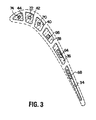
- One of these, as shown in Figure 3, has a rectangular cross-sectional shape but other shapes can be utilized.
- Figure 2 shows only two strengthening members simply for ease of understanding, while Figure 3 illustrates not only the strengthening members 64 and 66, but additional strengthening members 68, 70, 72 and 74 can be used, for example, one in each of the ceramic core sections 34, 36, 38, 40, 42 and 44.
- the cross-sectional shapes of the strengthening members can vary as between adjacent passages as shown in Figure 3, where some of the strengthening members are rectangular and others are circular in cross-section.
- additional core strengthening members 76 and 78 are shown extending through the cross-ties 56 and 58, respectively.
- strengthening members as described hereinabove can be employed in any or all of the serpentine cooling sections of the ceramic core, and/or in the cross-ties 56 and 58 of the core.
- the strengthening members should be made of a material which maintains structural rigidity at high molten metal pouring temperatures and, as noted above, materials such as alumina, quartz, molybdenum, tungsten and tungsten carbide are suitable, with alumina the presently preferred material.
- the strengthening members as described herein may also take the form of hollow tubes, and additional strength can be gained by filling the interior of the tubes with molybdenum or tungsten carbide or some other ceramic composition which would undergo a phase change during the casting process and become hard. Of course, in the event hollow strengthening members are utilized, the ends of the members would be sealed prior to injection of the ceramic material into the core die.
- the manner in which the above described strengthening members are placed and held within the ceramic core-forming die during the forming of the ceramic core is well within the skill of the art and need not be described in any detail here.
- the material is fired to cure the ceramic, thereby making the core stable and rigid.
- the ceramic core is then placed in the casting mold and made ready for pouring of the molten metal material to form the bucket.
- the strengthening members including alumina
- wax extensions can be added to one or both ends of the strengthening members so as to allow the strengthening members to expand axially under the high molten metal pouring temperatures. In other words, under high heat, the wax ends will melt and provide space for axial expansion of the tubes.
- the ceramic cores are normally removed by conventional leaching processes.
- the chemical leach bath can be modified to remove the rods as well. Alternatively, and depending on the size and location of the strengthening members, they can be physically removed through openings in the bucket.
Landscapes
- Engineering & Computer Science (AREA)
- Mechanical Engineering (AREA)
- Molds, Cores, And Manufacturing Methods Thereof (AREA)
- Turbine Rotor Nozzle Sealing (AREA)
- Compositions Of Oxide Ceramics (AREA)
Abstract
Description
Claims (10)
- A method of improving structural stability of a ceramic core used in the casing of hollow components comprising the steps of:a) providing a die having a predetermined geometry which gives the ceramic core a shape corresponding to interior spaces in the component;b) inserting elongated strengthening members into one or more interior areas of said die corresponding to said interior spaces;c) injecting a ceramic slurry into said die so as to substantially enclose said strengthening members; andd) firing the ceramic slurry to form a hardened ceramic core.
- The method of claim 1 wherein said strengthening members are comprised of alumina.
- The method of claim 1 wherein said die is configured to give the ceramic core a shape corresponding to internal coolant passages in a gas turbine bucket or nozzle.
- The method of claim 1 wherein said strengthening members are comprised of material having structural stability at temperatures in excess of 2600° F.
- A ceramic core used in a high temperature hollow component casting process, comprising:a ceramic body having a geometry corresponding to internal passages of a hollow component; andat least one elongated rod or tube incorporated in said ceramic body, said rod or tube comprised of a material which retains structural stability at temperatures in excess of about 2600° F.
- The ceramic core of claim 5 wherein said ceramic body has a geometry corresponding to internal coolant passages in a turbine bucket or nozzle.
- The ceramic core of claim 6 wherein said at least one strengthening member comprises at least a pair of elongated rods located in respective ones of said internal coolant passages.
- The ceramic core of claim 5 wherein said at least one rod or tube is composed of alumina.
- The ceramic core of claim 5 including a plurality of elongated rods or tubes.
- A method of casting a gas turbine component having interior passages, and including inserting a ceramic core into a casting die wherein the ceramic core is shaped to correspond to said interior passages, pouring molten metal into said die, solidifying said molten metal and extracting said ceramic core, and
incorporating at least one strengthening member in said ceramic core to improve structural stability of said core during pouring and solidifying said molten metal.
Applications Claiming Priority (2)
| Application Number | Priority Date | Filing Date | Title |
|---|---|---|---|
| US08/677,997 US5947181A (en) | 1996-07-10 | 1996-07-10 | Composite, internal reinforced ceramic cores and related methods |
| US677997 | 1996-07-10 |
Publications (2)
| Publication Number | Publication Date |
|---|---|
| EP0818256A1 true EP0818256A1 (en) | 1998-01-14 |
| EP0818256B1 EP0818256B1 (en) | 2004-02-25 |
Family
ID=24720952
Family Applications (1)
| Application Number | Title | Priority Date | Filing Date |
|---|---|---|---|
| EP97304905A Expired - Lifetime EP0818256B1 (en) | 1996-07-10 | 1997-07-04 | Composite, internal reinforced ceramic cores and related methods |
Country Status (5)
| Country | Link |
|---|---|
| US (1) | US5947181A (en) |
| EP (1) | EP0818256B1 (en) |
| JP (1) | JP4344787B2 (en) |
| CA (1) | CA2208377C (en) |
| DE (1) | DE69727729T2 (en) |
Cited By (21)
| Publication number | Priority date | Publication date | Assignee | Title |
|---|---|---|---|---|
| WO2001012361A2 (en) | 1999-06-24 | 2001-02-22 | Howmet Research Corporation | Ceramic core and method of making |
| GB2359042A (en) * | 1999-12-23 | 2001-08-15 | Alstom Power | Tool for producing casting cores |
| EP1834717A2 (en) * | 2001-10-24 | 2007-09-19 | United Technologies Corporation | Cores for use in precision investment casting |
| EP1930097A1 (en) * | 2006-12-09 | 2008-06-11 | Rolls-Royce plc | A core for use in a casting mould |
| FR2983420A1 (en) * | 2011-12-06 | 2013-06-07 | Michael Appleby | SYSTEMS, DEVICES AND / OR METHODS FOR FORMING HOLES |
| US9208916B2 (en) | 2001-06-05 | 2015-12-08 | Mikro Systems, Inc. | Methods for manufacturing three-dimensional devices and devices created thereby |
| US9206309B2 (en) | 2008-09-26 | 2015-12-08 | Mikro Systems, Inc. | Systems, devices, and/or methods for manufacturing castings |
| US9579714B1 (en) | 2015-12-17 | 2017-02-28 | General Electric Company | Method and assembly for forming components having internal passages using a lattice structure |
| US9968991B2 (en) | 2015-12-17 | 2018-05-15 | General Electric Company | Method and assembly for forming components having internal passages using a lattice structure |
| US9987677B2 (en) | 2015-12-17 | 2018-06-05 | General Electric Company | Method and assembly for forming components having internal passages using a jacketed core |
| US10046389B2 (en) | 2015-12-17 | 2018-08-14 | General Electric Company | Method and assembly for forming components having internal passages using a jacketed core |
| US10099284B2 (en) | 2015-12-17 | 2018-10-16 | General Electric Company | Method and assembly for forming components having a catalyzed internal passage defined therein |
| US10099276B2 (en) | 2015-12-17 | 2018-10-16 | General Electric Company | Method and assembly for forming components having an internal passage defined therein |
| US10099283B2 (en) | 2015-12-17 | 2018-10-16 | General Electric Company | Method and assembly for forming components having an internal passage defined therein |
| US10118217B2 (en) | 2015-12-17 | 2018-11-06 | General Electric Company | Method and assembly for forming components having internal passages using a jacketed core |
| US10137499B2 (en) | 2015-12-17 | 2018-11-27 | General Electric Company | Method and assembly for forming components having an internal passage defined therein |
| US10150158B2 (en) | 2015-12-17 | 2018-12-11 | General Electric Company | Method and assembly for forming components having internal passages using a jacketed core |
| US10286450B2 (en) | 2016-04-27 | 2019-05-14 | General Electric Company | Method and assembly for forming components using a jacketed core |
| US10335853B2 (en) | 2016-04-27 | 2019-07-02 | General Electric Company | Method and assembly for forming components using a jacketed core |
| WO2021062456A1 (en) | 2019-10-03 | 2021-04-08 | Fill Gesellschaft M.B.H. | Surface treatment method |
| WO2022126543A1 (en) * | 2020-12-17 | 2022-06-23 | 江苏方时远略科技咨询有限公司 | Valve-coating sand core |
Families Citing this family (25)
| Publication number | Priority date | Publication date | Assignee | Title |
|---|---|---|---|---|
| US6932145B2 (en) * | 1998-11-20 | 2005-08-23 | Rolls-Royce Corporation | Method and apparatus for production of a cast component |
| WO2001045877A2 (en) * | 1999-10-26 | 2001-06-28 | Howmet Research Corporation | Multi-wall core and process |
| ATE355918T1 (en) * | 1999-12-08 | 2007-03-15 | Gen Electric | CORE FOR ADJUSTING THE WALL THICKNESS OF A TURBINE BLADE AND METHOD |
| US20040094287A1 (en) * | 2002-11-15 | 2004-05-20 | General Electric Company | Elliptical core support and plug for a turbine bucket |
| US20050000674A1 (en) * | 2003-07-01 | 2005-01-06 | Beddard Thomas Bradley | Perimeter-cooled stage 1 bucket core stabilizing device and related method |
| US6966756B2 (en) * | 2004-01-09 | 2005-11-22 | General Electric Company | Turbine bucket cooling passages and internal core for producing the passages |
| US20080028606A1 (en) * | 2006-07-26 | 2008-02-07 | General Electric Company | Low stress turbins bucket |
| US7690894B1 (en) | 2006-09-25 | 2010-04-06 | Florida Turbine Technologies, Inc. | Ceramic core assembly for serpentine flow circuit in a turbine blade |
| US20080110024A1 (en) * | 2006-11-14 | 2008-05-15 | Reilly P Brennan | Airfoil casting methods |
| US7762774B2 (en) * | 2006-12-15 | 2010-07-27 | Siemens Energy, Inc. | Cooling arrangement for a tapered turbine blade |
| US9017027B2 (en) * | 2011-01-06 | 2015-04-28 | Siemens Energy, Inc. | Component having cooling channel with hourglass cross section |
| CN102489668A (en) * | 2011-12-06 | 2012-06-13 | 辽宁速航特铸材料有限公司 | Method for solving cracking of ceramic core by pre-burying fire-resistant rope |
| US8261810B1 (en) | 2012-01-24 | 2012-09-11 | Florida Turbine Technologies, Inc. | Turbine airfoil ceramic core with strain relief slot |
| US9713838B2 (en) * | 2013-05-14 | 2017-07-25 | General Electric Company | Static core tie rods |
| US10072503B2 (en) | 2013-08-14 | 2018-09-11 | Elwha Llc | Dual element turbine blade |
| DE102014207791A1 (en) * | 2014-04-25 | 2015-10-29 | Siemens Aktiengesellschaft | Method for investment casting of metallic components |
| US9649687B2 (en) * | 2014-06-20 | 2017-05-16 | United Technologies Corporation | Method including fiber reinforced casting article |
| GB201503640D0 (en) * | 2015-03-04 | 2015-04-15 | Rolls Royce Plc | A core for an investment casting process |
| FR3034128B1 (en) * | 2015-03-23 | 2017-04-14 | Snecma | CERAMIC CORE FOR MULTI-CAVITY TURBINE BLADE |
| US10697305B2 (en) * | 2016-01-08 | 2020-06-30 | General Electric Company | Method for making hybrid ceramic/metal, ceramic/ceramic body by using 3D printing process |
| US10443403B2 (en) | 2017-01-23 | 2019-10-15 | General Electric Company | Investment casting core |
| GB201701365D0 (en) * | 2017-01-27 | 2017-03-15 | Rolls Royce Plc | A ceramic core for an investment casting process |
| US10626797B2 (en) | 2017-02-15 | 2020-04-21 | General Electric Company | Turbine engine compressor with a cooling circuit |
| US10981217B2 (en) | 2018-11-19 | 2021-04-20 | General Electric Company | Leachable casting core and method of manufacture |
| US11021968B2 (en) * | 2018-11-19 | 2021-06-01 | General Electric Company | Reduced cross flow linking cavities and method of casting |
Citations (6)
| Publication number | Priority date | Publication date | Assignee | Title |
|---|---|---|---|---|
| US3160931A (en) * | 1961-01-03 | 1964-12-15 | Union Carbide Corp | Core casting method |
| GB1549819A (en) * | 1976-11-03 | 1979-08-08 | Thermal Syndicate Ltd | Reinforced vitreous silica casting core |
| GB2102317A (en) * | 1981-07-03 | 1983-02-02 | Rolls Royce | Internally reinforced core for casting |
| EP0105602A2 (en) * | 1982-09-02 | 1984-04-18 | PCC Airfoils, Inc. | Mold core and method of forming internal passages in an airfoil |
| US4905750A (en) * | 1988-08-30 | 1990-03-06 | Amcast Industrial Corporation | Reinforced ceramic passageway forming member |
| GB2281238A (en) * | 1993-08-23 | 1995-03-01 | Rolls Royce Plc | improvements in investment casting using chaplets |
-
1996
- 1996-07-10 US US08/677,997 patent/US5947181A/en not_active Expired - Lifetime
-
1997
- 1997-06-20 CA CA002208377A patent/CA2208377C/en not_active Expired - Lifetime
- 1997-07-04 EP EP97304905A patent/EP0818256B1/en not_active Expired - Lifetime
- 1997-07-04 DE DE69727729T patent/DE69727729T2/en not_active Expired - Lifetime
- 1997-07-08 JP JP18192197A patent/JP4344787B2/en not_active Expired - Lifetime
Patent Citations (6)
| Publication number | Priority date | Publication date | Assignee | Title |
|---|---|---|---|---|
| US3160931A (en) * | 1961-01-03 | 1964-12-15 | Union Carbide Corp | Core casting method |
| GB1549819A (en) * | 1976-11-03 | 1979-08-08 | Thermal Syndicate Ltd | Reinforced vitreous silica casting core |
| GB2102317A (en) * | 1981-07-03 | 1983-02-02 | Rolls Royce | Internally reinforced core for casting |
| EP0105602A2 (en) * | 1982-09-02 | 1984-04-18 | PCC Airfoils, Inc. | Mold core and method of forming internal passages in an airfoil |
| US4905750A (en) * | 1988-08-30 | 1990-03-06 | Amcast Industrial Corporation | Reinforced ceramic passageway forming member |
| GB2281238A (en) * | 1993-08-23 | 1995-03-01 | Rolls Royce Plc | improvements in investment casting using chaplets |
Cited By (31)
| Publication number | Priority date | Publication date | Assignee | Title |
|---|---|---|---|---|
| EP1244524A2 (en) * | 1999-06-24 | 2002-10-02 | Howmet Research Corporation | Ceramic core and method of making |
| EP1244524A4 (en) * | 1999-06-24 | 2007-08-22 | Howmet Res Corp | Ceramic core and method of making |
| WO2001012361A2 (en) | 1999-06-24 | 2001-02-22 | Howmet Research Corporation | Ceramic core and method of making |
| GB2359042A (en) * | 1999-12-23 | 2001-08-15 | Alstom Power | Tool for producing casting cores |
| US10189184B2 (en) | 2001-06-05 | 2019-01-29 | United Technologies Corporation | Methods for manufacturing three-dimensional devices and devices created thereby |
| US9208916B2 (en) | 2001-06-05 | 2015-12-08 | Mikro Systems, Inc. | Methods for manufacturing three-dimensional devices and devices created thereby |
| EP1834717A3 (en) * | 2001-10-24 | 2008-10-01 | United Technologies Corporation | Cores for use in precision investment casting |
| EP1834717A2 (en) * | 2001-10-24 | 2007-09-19 | United Technologies Corporation | Cores for use in precision investment casting |
| US7993106B2 (en) | 2006-12-09 | 2011-08-09 | Rolls-Royce Plc | Core for use in a casting mould |
| EP1930097A1 (en) * | 2006-12-09 | 2008-06-11 | Rolls-Royce plc | A core for use in a casting mould |
| US9206309B2 (en) | 2008-09-26 | 2015-12-08 | Mikro Systems, Inc. | Systems, devices, and/or methods for manufacturing castings |
| US10207315B2 (en) | 2008-09-26 | 2019-02-19 | United Technologies Corporation | Systems, devices, and/or methods for manufacturing castings |
| FR2983420A1 (en) * | 2011-12-06 | 2013-06-07 | Michael Appleby | SYSTEMS, DEVICES AND / OR METHODS FOR FORMING HOLES |
| GB2500449A (en) * | 2011-12-06 | 2013-09-25 | Mikro Systems Inc | Producing holes in metal castings |
| GB2500449B (en) * | 2011-12-06 | 2014-08-20 | Mikro Systems Inc | Systems, devices, and/or methods for producing holes |
| US9968991B2 (en) | 2015-12-17 | 2018-05-15 | General Electric Company | Method and assembly for forming components having internal passages using a lattice structure |
| US10137499B2 (en) | 2015-12-17 | 2018-11-27 | General Electric Company | Method and assembly for forming components having an internal passage defined therein |
| US10046389B2 (en) | 2015-12-17 | 2018-08-14 | General Electric Company | Method and assembly for forming components having internal passages using a jacketed core |
| US10099284B2 (en) | 2015-12-17 | 2018-10-16 | General Electric Company | Method and assembly for forming components having a catalyzed internal passage defined therein |
| US10099276B2 (en) | 2015-12-17 | 2018-10-16 | General Electric Company | Method and assembly for forming components having an internal passage defined therein |
| US10099283B2 (en) | 2015-12-17 | 2018-10-16 | General Electric Company | Method and assembly for forming components having an internal passage defined therein |
| US10118217B2 (en) | 2015-12-17 | 2018-11-06 | General Electric Company | Method and assembly for forming components having internal passages using a jacketed core |
| US9987677B2 (en) | 2015-12-17 | 2018-06-05 | General Electric Company | Method and assembly for forming components having internal passages using a jacketed core |
| US10150158B2 (en) | 2015-12-17 | 2018-12-11 | General Electric Company | Method and assembly for forming components having internal passages using a jacketed core |
| US9975176B2 (en) | 2015-12-17 | 2018-05-22 | General Electric Company | Method and assembly for forming components having internal passages using a lattice structure |
| US9579714B1 (en) | 2015-12-17 | 2017-02-28 | General Electric Company | Method and assembly for forming components having internal passages using a lattice structure |
| US10286450B2 (en) | 2016-04-27 | 2019-05-14 | General Electric Company | Method and assembly for forming components using a jacketed core |
| US10335853B2 (en) | 2016-04-27 | 2019-07-02 | General Electric Company | Method and assembly for forming components using a jacketed core |
| US10981221B2 (en) | 2016-04-27 | 2021-04-20 | General Electric Company | Method and assembly for forming components using a jacketed core |
| WO2021062456A1 (en) | 2019-10-03 | 2021-04-08 | Fill Gesellschaft M.B.H. | Surface treatment method |
| WO2022126543A1 (en) * | 2020-12-17 | 2022-06-23 | 江苏方时远略科技咨询有限公司 | Valve-coating sand core |
Also Published As
| Publication number | Publication date |
|---|---|
| EP0818256B1 (en) | 2004-02-25 |
| CA2208377A1 (en) | 1998-01-10 |
| DE69727729D1 (en) | 2004-04-01 |
| CA2208377C (en) | 2006-06-06 |
| DE69727729T2 (en) | 2004-12-02 |
| US5947181A (en) | 1999-09-07 |
| JP4344787B2 (en) | 2009-10-14 |
| JPH1080747A (en) | 1998-03-31 |
Similar Documents
| Publication | Publication Date | Title |
|---|---|---|
| US5947181A (en) | Composite, internal reinforced ceramic cores and related methods | |
| US4532974A (en) | Component casting | |
| EP0099215B1 (en) | Method for manufacture of ceramic casting moulds | |
| US4728258A (en) | Turbine engine component and method of making the same | |
| EP1142658B1 (en) | Reinforced ceramic shell molds, and related processes | |
| JP2017064785A (en) | Casting core apparatus and casting method | |
| GB2102317A (en) | Internally reinforced core for casting | |
| US11014151B2 (en) | Method of making airfoils | |
| US20090165988A1 (en) | Turbine airfoil casting method | |
| EP0768130B1 (en) | Turbine nozzle and related casting method for optimal fillet wall thickness control | |
| US8074701B2 (en) | Method for producing a pattern for the precision-cast preparation of a component comprising at least one cavity | |
| US9802248B2 (en) | Castings and manufacture methods | |
| US11014152B1 (en) | Method of making complex internal passages in turbine airfoils | |
| RU2093304C1 (en) | Cooled turbine blade and method for its manufacture | |
| US11014153B2 (en) | Method for seeding a mold | |
| CN109663888B (en) | Method for mold seeding | |
| JPS6030549A (en) | Production of casting having fine hole | |
| EP3246108A1 (en) | Methods for fabricating cast components with cooling channels | |
| JPH0234705B2 (en) | CHUZOYONAKAGOOYOBICHUZOHOHO | |
| RU2094170C1 (en) | Method for manufacture of cooled gas turbine engine blade and cooled blade of gas turbine engine | |
| EP3626932B1 (en) | Method of manufacturing a cooled component for a gas turbine engine | |
| US20190375000A1 (en) | Method for casting cooling holes for an internal cooling circuit of a gas turbine engine component | |
| JPS6057417B2 (en) | Casting method for gas turbine blades |
Legal Events
| Date | Code | Title | Description |
|---|---|---|---|
| PUAI | Public reference made under article 153(3) epc to a published international application that has entered the european phase |
Free format text: ORIGINAL CODE: 0009012 |
|
| AK | Designated contracting states |
Kind code of ref document: A1 Designated state(s): CH DE FR GB IT LI |
|
| 17P | Request for examination filed |
Effective date: 19980714 |
|
| AKX | Designation fees paid |
Free format text: CH DE FR GB IT LI |
|
| RBV | Designated contracting states (corrected) |
Designated state(s): CH DE FR GB IT LI |
|
| 17Q | First examination report despatched |
Effective date: 19981012 |
|
| GRAH | Despatch of communication of intention to grant a patent |
Free format text: ORIGINAL CODE: EPIDOS IGRA |
|
| GRAS | Grant fee paid |
Free format text: ORIGINAL CODE: EPIDOSNIGR3 |
|
| GRAA | (expected) grant |
Free format text: ORIGINAL CODE: 0009210 |
|
| AK | Designated contracting states |
Kind code of ref document: B1 Designated state(s): CH DE FR GB IT LI |
|
| REG | Reference to a national code |
Ref country code: GB Ref legal event code: FG4D |
|
| REG | Reference to a national code |
Ref country code: CH Ref legal event code: EP |
|
| REG | Reference to a national code |
Ref country code: CH Ref legal event code: NV Representative=s name: SERVOPATENT GMBH |
|
| REF | Corresponds to: |
Ref document number: 69727729 Country of ref document: DE Date of ref document: 20040401 Kind code of ref document: P |
|
| ET | Fr: translation filed | ||
| PLBE | No opposition filed within time limit |
Free format text: ORIGINAL CODE: 0009261 |
|
| STAA | Information on the status of an ep patent application or granted ep patent |
Free format text: STATUS: NO OPPOSITION FILED WITHIN TIME LIMIT |
|
| 26N | No opposition filed |
Effective date: 20041126 |
|
| REG | Reference to a national code |
Ref country code: CH Ref legal event code: PFA Owner name: GENERAL ELECTRIC COMPANY Free format text: GENERAL ELECTRIC COMPANY#1 RIVER ROAD#SCHENECTADY, NY 12345 (US) -TRANSFER TO- GENERAL ELECTRIC COMPANY#1 RIVER ROAD#SCHENECTADY, NY 12345 (US) |
|
| REG | Reference to a national code |
Ref country code: FR Ref legal event code: PLFP Year of fee payment: 20 |
|
| PGFP | Annual fee paid to national office [announced via postgrant information from national office to epo] |
Ref country code: GB Payment date: 20160727 Year of fee payment: 20 Ref country code: DE Payment date: 20160726 Year of fee payment: 20 Ref country code: CH Payment date: 20160727 Year of fee payment: 20 Ref country code: IT Payment date: 20160722 Year of fee payment: 20 |
|
| PGFP | Annual fee paid to national office [announced via postgrant information from national office to epo] |
Ref country code: FR Payment date: 20160726 Year of fee payment: 20 |
|
| REG | Reference to a national code |
Ref country code: DE Ref legal event code: R071 Ref document number: 69727729 Country of ref document: DE |
|
| REG | Reference to a national code |
Ref country code: CH Ref legal event code: PL |
|
| REG | Reference to a national code |
Ref country code: GB Ref legal event code: PE20 Expiry date: 20170703 |
|
| PG25 | Lapsed in a contracting state [announced via postgrant information from national office to epo] |
Ref country code: GB Free format text: LAPSE BECAUSE OF EXPIRATION OF PROTECTION Effective date: 20170703 |