The present invention relates to a radio conference system in
which a hub station and a plurality of terminal stations interchange data
with each other and, more particularly, to a terminal unit guiding
technology for insuring a high transmission efficiency between the
terminal stations and the hub station.
Some different transmission protocols have been proposed for
a radio conference system in order to implement sure communication and
high transmission efficiency between a single hub station and a plurality
of terminal stations. For example, a polling system allows a hub station
to send data to terminal stations and then confirm receipt terminal station
by terminal station. Another system allows the individual terminal station
to detect an error out of data received from a hub station and return a
resend request signal (NAK) to the hub station. Further, a receipt terminal
may include a display for displaying communication quality between it
and a hub station in terms of a receipt electric field strength.
However the conventional schemes described above each has
some problems left unsolved, as follows. Although sure transmission is
expected with the polling system, polling wastes time when it comes to a
conference system in which radio communication is used at a visible
distance. Specifically, this kind of conference system does not need strict
confirmation of transmission and receipt because most terminal stations
are given acceptable communication quality. Therefore, causing all the
terminal stations to acknowledge receipt by polling needs an extra period
of time and lowers the data transfer efficiency.
The NAK scheme saves the above station-by-station polling
time by determining that a terminal station having returned no NAK
signals within a preselected period of time has received data correctly.
However, the problem with the NAK scheme is that when any one of
many terminal stations is put in a low wave propagation condition, the
hub station repeats resending exclusively for such a terminal station.
Therefore, the hub station cannot send the next data to the terminal
stations until it ends the resending operation meant for the terminal station
in question, i.e., until it sends the data to all the terminal stations. As a
result, if at least one of the terminal stations is of low propagation quality,
the overall transmission efficiency of the system falls.
The display scheme capable of displaying the receipt electric
field allows each terminal unit to be moved to a location where the wave
propagation quality is relatively high in accordance with the display.
Such mobility of the terminal unit increases the overall data transfer
efficiency of the entire system. However, it is not easy even for an expert
in the radio communications art to determine the degree of the receipt
electric field strength which insures error-free data transmission.
Moreover, in the case of packet transmission, the measurement of the
electric field strength itself is sometimes difficult because the hub station
does not always send an electromagnetic wave continuously.
It is therefore an object of the present invention to provide a
radio conference system capable of guiding the participants of a radio
conference and carrying terminal stations to adequate locations in relation
to a hub station, and thereby enhancing the efficient data distribution from
the hub station to the terminal stations.
In accordance with the present invention, a radio conference
system has a hub station and a plurality of terminal stations each being
capable of receiving data from the hub station. The hub station includes
a distributing section for distributing information consisting of data and
an error checking code to the terminal stations, a resending section for
identifying, on receiving a resend request signal from any one of the
terminal stations, the terminal station sent the resend request signal, and
then resending the information, a plurality of counters respectively
assigned to the terminal stations each for counting the resend request
signals received from the terminal station associated therewith, and an
alarming section for displaying alarm information indicative of the
terminal station associated with the counter whose count has exceeded a
preselected count. The terminal units each includes a detecting section for
detecting an error out of the information sent from the hub station, and a
resend request sending section for sending, when the detecting section
detects an error, the resend request signal including identification
information identifying the terminal station.
In the above system, a chairman operating the hub station can
urge a participant carrying the displayed terminal station to move to a
location where the wave receipt condition is better. As a result, the
frequency of generation of the resend request signal is successfully
reduced, and the overall transmission efficiency of the system is
enhanced.
Further, in accordance with the present invention, a radio
conference system also has a hub station, and a plurality of terminal
stations each being capable of receiving information from the hub station.
The hub station includes a distributing section for distributing information
consisting of data and an error checking code to the terminal stations, and
a resending section for resending the information on receiving a resend
request signal from any one of the terminal stations. The terminal stations
each includes a detecting section for detecting an error out of the
information received from the hub station, a resend request sending
section for sending, when the detecting section detects an error, the resend
request signal including identification information identifying the terminal
station, a counter for counting the resent request signals sent, and an
alarming section for displaying alarm information showing that a count of
the counter has exceeded a preselected count.
In the above system, a participant holding the terminal station
with the alarm information can move to a location of better wave receipt
condition spontaneously. This also lowers the frequency of generation of
the resend request signal and thereby enhances the overall transmission
efficiency of the system.
The above and other objects, features and advantages of the
present invention will become apparent from the following detailed
description taken with the accompanying drawings in which:
Referring to FIG. 1 of the drawings, a radio conference system
embodying the present invention is shown and includes a hub station 1
and a terminal station 2. As shown, the hub station 1 and terminal station
2 are identical in configuration, i.e., they are identical terminal units.
One of the two terminal units 1 and 2 held by the chairman of a
conference plays the role of a hub station while the other terminal unit
held by a participant plays the role of the terminal station. In this sense,
the distinction between the hub station and the terminal station is only a
matter of convenience.
The hub station 1 includes an operation/display section 11 for
allowing data necessary for the terminal itself to be input thereon, while
displaying received data. A radio section 13 sends data or receives data
via an antenna 14. A first memory (MEM) 15 stores data to be sent or
data received from another terminal unit for a moment. A second memory
(MEM) 16 stores data for estimating the receiving states of terminal
stations. A control section 12 executes control which will be described.
The terminal station 2 has the same construction as the hub station 1, as
mentioned earlier.
A single hub station 1 is selected by the chairman of a
conference on the operation/display section 1. The control section 12 of
the terminal unit to play the role of the hub station causes the terminal unit
to operate in a hub station mode and causes each of the other terminal
units to operate in a terminal station mode.
The terminal station 2 is a portable unit carried by the
participant of a conference; in practice, a plurality of terminal stations are
each held by one of a plurality of participants. While the chairman and
participants are generally positioned within earshot, the range of earshot
may not coincide with the range of propagation of an electromagnetic
wave, depending on the conditions of a conference room or the ability of
a radio system used for a conference.
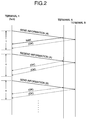
FIG. 2 demonstrates resend control particular to radio
transmission which allows identical information to be sent to a plurality
of terminal stations at the same time. The control section 12 of the hub
station 1 divides information to be distributed and stored in the memory
15 beforehand into a plurality of blocks, adds a CRC (Cyclic Redundancy
Check) or similar error checking code to each block of information, and
then broadcasts the information via the radio section 13 and antenna 14
block by block.
FIG. 2 shows the resend control beginning with the step of
broadcasting information a as a single transmission block. As shown,
terminal stations A and B (representative of a plurality of terminal
stations) each receives one block of information from the hub station or
terminal 1. In response, the terminal stations A and B each causes its
control section 12 to determine whether or not a transmission error has
occurred in the received information a on the basis of the CRC code. If
the information a is free from errors, the terminal station A or B writes the
information in the MEM 15 and then waits for the next block of data from
the hub station 1. At this instant, the terminal station A or B received the
error-free information does not inform the hub station 1 of the receipt of
the correct information, as indicated by a dashed line (OK) in FIG. 2.
This is because the probability of error-free transmission is high with a
conference system in which a number of terminal stations gather in the
same environment of relatively high wave propagation quality; returning
an acknowledgement each time would simply waste time. However,
when the control section 12 detect an error in the received information, the
terminal station A or B including the control section 12 returns a NAK
signal to the hub station 1 until it receives the information correctly.
In FIG. 2, it is assumed that the terminal station A has detected
an error in the received information a and returned the NAK signal while
the terminal station B has received the information a correctly. On
receiving the NAK signal within a preselected period of time t since the
broadcasting of the information a, the hub station 1 again broadcasts the
same information a (resending). FIG. 2 shows a condition wherein the
terminal station A receives the resent information correctly and therefore
does not return the NAK signal, and then the hub station 1 broadcasts the
next block of information b on the elapse of the next period of time t. In
FIG. 2, both the terminal stations A and B are assumed to receive the
information b correctly.
The resending system illustrated in FIG. 2 is a remedy against
the temporary disturbance to the propagation of an electromagnetic wave.
The problem is that any one of the terminal stations may continuously
generate the NAK signal because it is located at a position where the
receipt condition is poor; then, the hub station would repeat resending
without broadcasting the next information. While this problem may be
solved if the number of times of resending is limited, even such an
implementation lowers the overall transmission efficiency of the system
including many other terminal stations.
The continuous generation of the NAK signal by a certain
terminal station means that the wave propagation condition between the
terminal station and the hub station is poor. The best solution to the above
problem is to, if the terminal station is mobile, cause the terminal station
to move to a position of good wave propagation condition. This can be
done if the participant carrying the terminal station in question is informed
of the continuous generation of the NAK signal and urged to move to the
adequate position. Two different procedures for urging the above
participant to move to the adequate position will be described hereinafter.
A first procedure is executed by the hub station 1, FIG. 1, as
follows. For this procedure, the hub station 1 includes counters each
assigned to a particular terminal station. The counters each indicates the
number of times of receipt of the NAK signal from the associated terminal
station on the basis of a terminal ID code included in the NAK signal.
Every time the hub station 1 receives the NAK signal from any one of the
terminal stations, it increments the counter assigned to that terminal
station by 1 (one). When the counter reaches a preselected value, the hub
station 1 displays the ID code assigned to the above terminal unit together
with an alarm on the operation/display section 11. At the same time, the
hub station 1 may advantageously output an alert in the form of vibration
or tone because the chairman may not be watching the display section 11
by accident.
The chairman, watching the alarm appearing on the hub station
1, urges the participant carrying the terminal station in question to move
to a position of good wave propagation condition. If desired, the ID codes
and the names of the participants may be registered in the hub station 1
beforehand in one-to-one correspondence, so the ID code for alarming can
be replaced with the participant's name. After alarming the participant,
the hub station 1 causes its control section 12 to reset the counter reached
the preselected value. Alternatively, the chairman may reset the counter
on the operation/display section 11.
The above control is executed by the control section 12
implemented as, e.g., a microprocessor. A program for the
microprocessor is stored in a ROM (Read Only Memory) or similar
storage, not shown, beforehand.
The operation of the control section 12 included in the hub
station 1 and that of the control section 12 included in each terminal
station in accordance with the first procedure will be described more
specifically with reference to FIG. 3. The two stations 1 and 2 shown in
FIG. 1 can each play the role of a hub station or a terminal station,
depending on the operation mode set on the operation/display section 11,
as stated earlier. As shown in FIG. 3, the control section 12 of each
terminal station 1 or 2 determines whether or not a hub station mode
command has been input on the operation/display section 11 (step S101).
If the answer of the step S101 is positive (Y), the control section 12
executes a sequence of steps S102 through S109. If the answer of the step
S101 is negative (N), meaning that the control section 12 should set up a
terminal station mode, it executes a sequence of steps S110 through S112.
Consequently, the control section 12 of the hub station 1 executes the
steps S102 through S109 while the control section 12 of the terminal
station 2 executes the steps S110 through S112.
Specifically, the control section 12 of the hub station 1 resets all
the counters C(i) (i = 1, 2, ..., I; I being the number of terminal stations)
respectively assigned to the terminal stations (step S102). Then, the
control section 12 reads one block of data to be distributed out of the
MEM 15, adds a block number, error checking code and so forth to the
block, and then delivers them to the radio section 13. The radio section
13 broadcasts the input data to all the terminal stations via the antenna 104
(step S103). Subsequently, the control section 12 determines whether or
not the NAK signal has been received from any one of the terminal
stations within the period of time t since the transmission of the data (step
S104). If the answer of the step S104 is N, the control section 12 returns
to the step 103 so as to broadcast the next block of data.
If the answer of the step S104 is Y, the control section 12 of the
hub station 1 again causes the radio section 13 to broadcast the same data
(step S105), and increments the counter C(j) assigned to the terminal
station j sent the NAK signal by 1 (step S106). Then, the control section
12 determines whether or not the count of the counter C(j) has exceeded
a preselected threshold TH (step So). If the answer of the step So is
negative, the program returns to the step S104 to see if the terminal station
j has again sent the NAK signal in response to the resent data or not.
When the counter C(j) exceeds the threshold TH (Y, step So), the control
section 12 displays an alarm relating to the terminal station j on the
operation/display section 11 (step 108). Thereafter, the control section 12
resets the counter C(j) (step 109), returns to the step S104, and then
determines whether or not the terminal station has again sent the NAK
signal in response to the data resent in the step S105.
On the other hand, the control section 12 of the terminal station
2 receives the data sent from the hub station 1 via the radio section 13
(step S110). The control section 12 neglects the received data if the data
is the resent data and if the terminal station 12 has already received the
same data correctly. This decision can be done on the basis of the block
number included in the receive data. Subsequently, the control section 12
determines, based on the error checking code added to the data, whether
or not the received data is correct (step S111). If the answer of the step
S111 is Y, the control section 12 writes the received data in the MEM 15
(step S112) and then returns to the step S110 for waiting for the next data.
If the received data includes an error, as determined in the step S111, the
control section 12 sends the NAK signal to the hub station 1 (step S113)
and then returns to the step 110 for waiting for the resending of the data.
A second procedure for urging the participant to move to an
adequate position is executed only by the terminal station 2, as follows.
Every time the terminal station 2 sends the NAK signal to the hub station
1, it increments a counter d included in the memory 16 by 1. When the
counter d reaches a preselected count, the terminal 2 displays an alarm on
the operation/display section 11 thereof.
In the second procedure, the participant carrying the terminal
unit 2 moves to an adequate position in response to the alarm and then
operates the operation/display section 11 for resetting the counter d. Of
course, the controller 12 may automatically reset the counter d at the same
time as it displays the alarm. In this procedure, the alarm may be
implemented by an alert tone or vibration in place of or in combination
with the display.
Reference will be made to FIG. 4 for describing the operation
of the control section 12 of the hub station 1 and that of the control section
of the terminal station 2 particular to the second procedure. As shown, the
control section 12 of the hub station 1 executes steps S202 through S204
while the control section 12 of the terminal station 2 executes steps S205
through S213. As for the hub station 1, the steps S102 through S109
shown in FIG. 3 also occur except for the omission of the steps 102 and
S106 through S109, and therefore steps S202 through S204 shown in FIG.
4 will not be described. in order to avoid redundancy.
As shown in FIG. 4, the control section 12 included in the
terminal station 2 rests the counter d for counting the NAK signals sent to
the hub station 1 (step S205). The control section 12 receives the data
sent from the hub station 1 via the radio section 13 (step S206). The
control section 12 neglects the received data if the data is the resent data
and if the terminal station 12 has already received the same data correctly.
Subsequently, the control section 12 determines, based on the error
checking code added to the received data, whether or not an error exists
in the data (step S207). If the answer of the step S207 is Y, the control
section 12 writes the received data in the MEM 15 of the terminal unit 2
(step S208) and then returns to the step S206.
If the answer of the step S207 is N, meaning that the received
data includes an error, the control section 12 sends the NAK signal to the
hub station 1 (step S209) and increments the counter d by 1 (step S210).
Then, the control section 12 determines whether or not the counter d has
exceeded the threshold TH (step S211). If the answer of the step S211 is
N, the control section 12 returns to the step S206. If the answer of the
step S211 is Y, the control section 12 displays an alarm on the
operation/display section 11 (step S212), resets the counter d (step S213),
and then returns to the step S206 for awaiting the resending of the data.
In summary, in accordance with the present invention, a radio
conference system gives an alarm to the participant of a conference either
directly or via a chairman, urging the participant to move to a position of
good wave propagation condition between a terminal station held by the
participant and a hub station assigned to the chairman. This prevents the
transmission efficiency of the entire system, including may other terminal
stations, from being lowered due to a remedy against the defective wave
propagation to only a small number of terminal stations.
Modifications of the invention herein disclosed will occur to a
person skilled in the art and all such modifications are deemed to be
within the scope of the invention as defined by the appended claims.