BACKGROUND OF THE INVENTION
The invention is in the field of display technology and deals
specifically with processing color and gray scale data which is to
be sent to a color or gray scale monitor or to a color laser
printer or other continuous raster scan device using a novel
mechanism for handling complex graphics operatives. The invention
is part of the continuing evolution of software and hardware
graphics and memory reduction technology to enable the printing
and display of complex graphics images using less memory than
would be the case without using the invented techniques.
The invention specifically addresses complex logic applied to
continuous-tone data using new operatives called filter
operations.
SUMMARY OF THE INVENTION
A novel approach to handling transparency operatives
simultaneously with raster operatives in a graphics environment is
disclosed. This is achieved by introducing filter operations to
obtain the effect of transparency. Filter operations work
cooperatively with grayscale and continuous-tone color raster
operations. The introduction of filter operations, and their
cooperation with raster operations allows this otherwise
computationally complex problem to be served by a single hardware
circuit. The efficiency of this approach lends itself well to
real-time applications such as monochrome and color laser
printing. The solution is also applicable to displaying complex
graphics on a video display device.
This description first introduces raster operations and
transparency. This is followed by a discussion of the difficulties
of prior art approaches to solving the problem of combining these
two mechanisms. Treating transparency as a filtration process
allows a different view of this problem. The invention introduces
and demonstrates this filtration process. Although this solution
is efficient in software, it also lends itself well to hardware
parallelism, hence eliminating the step-by-step or sequential
computational process which the prior art approach imposes. This
solution is described and a high-level circuit diagram that
demonstrates the ability to achieve the cooperative result using
parallel computation is shown.
BRIEF DESCRIPTION OF THE DRAWINGS
Figure 1 is a block diagram of a system showing the
environment in which the present invention may be used.
Figure 2 is a representation of pixels forming a rectangular
grid.
Figure 3 is a flowchart showing the cooperative evaluation
algorithm.
Figure 4 is a block diagram of a circuit for implementing the
cooperative evaluation algorithm described in Figure 3 for three
operands.
Figure 5 is a block diagram of a circuit for implementing the
preferred embodiment of the cooperative evaluation algorithm for
two operands.
DETAILED DESCRIPTION OF THE INVENTION
Figure 1 is a block diagram of a system showing the
environment in which the present invention may be used. In U.S.
Patent No. 5,204,804, a method and apparatus for generating
graphics information for display on a continuous synchronous
raster output device is disclosed. The system is shown in Figure
4 of U.S. Patent No. 5,204,804 and is for printing on monochrome
output devices. The present invention is directed to improvements
in the system described in U.S. Patent No. 5,204,804 to handle
color images as well as monochrome images. The basic graphics
orders described in U.S. Patent No. 5,204,804 are enhanced to
support color and additional orders are defined for filters and
other operations as described below. In this connection, as fully
explained in U.S. Patent No. 5,204,804, an image which is
generated by a computer program, when it is being processed for
display or printing is represented by generated commands that draw
pixels which correspond to the image to be displayed or printed.
In the invention described in U.S. Patent No. 5,204,804, unlike
the prior art, these commands are converted to graphics orders
rather than directly to bitmaps. The graphics orders take up much
less memory than corresponding bitmaps, but can be converted to
bitmaps for sending to a continuous synchronous raster output
device such as a laser printer at a speed fast enough to keep up
with the print engine. Figure 1 herein is similar to Figure 4 of
U.S. Patent No. 5,204,804. However, in Figure 1 herein, not all
of the functional blocks shown in Figure 4 appear as such blocks
are not needed for an understanding of the present invention which
relates mostly to improvements in the realtime blit processor 37
of Figure 4 which is designated as realtime image generator 21 in
Figure 1.
Functionally, the enhancements to the basic orders described
in U.S. Patent No. 5,204,804 and additional orders defined for
filters and other operations needed for operation of the present
invention provide transparency information to realtime blit
processor 37, also referred to as the graphics execution unit
(GEU) in U.S. Patent No. 5,204,804. This includes the following
information (1) a two operand filter function F(PF, SF) or,
optionally, a three-operand filter function F(PF, SF, DF); (2) the
source filter bitmap, SF, (3) a pattern filter bitmap, PF; and (4)
a destination bitmap DF, if the three-operand filter function is
used. In U.S. Patent No. 5, 502, 804, the term "halftone" is used
instead of "pattern" and halftone mask is used instead of pattern
filter bitmap.
More specifically, the additional orders defined for filters
and other operations needed for operation of the invention perform
the following functions:
| Set Filter Boolean | Sets a hardware "register" with a boolean value that will be used in the next and subsequent operations until another Set Filter Boolean command replaces it. |
| Set Source Filter Address | Sets the starting address of the source filter to be used until another Set Source Filter command replaces it. |
| Set Pattern Filter Address | Sets the starting address of the pattern filter to be used until another Set Pattern Filter command replaces it. |
Further information regarding these orders or commands is
provided below in connection with the description of hardware
commands/operations which could be used to perform cooperative
filter and raster operations according to the present invention
with respect to the correct evaluation example shown in Table 4
below.
The functional block elements of Figure 1 perform the same
functions as their correspondingly numbered functional block
elements of Figure 4 of U.S. Patent No. 5,502,804 and, therefore
are not described herein. Host application 11 of Figure 1
corresponds to PDL interpreter 21 of Figure 4, and as previously
pointed out, realtime image generator 21 of Figure 1 corresponds
to realtime Blit processor 37 of Figure 4. The additions to
realtime image generator needed for an understanding of the
present invention are described below.
The following is a definition/description of various terms
employed herein.
Raster Graphics Data
Raster graphics data is a rectangular grid where each grid
element is a called a pixel. An example is shown in Figure 1. The
size of the grid is described in terms of width and height. A
pixel can be uniquely identified by its 〈x, y〉 coordinate, where
1≤x≤width and 1≤y≤height, within the rectangular grid. If G is a
rectangular grid, a pixel is denoted within G as G〈x, y〉.
A pixel can be broken down into components and depth. A pixel
component represents the contribution of a primary color to the
pixel. In a monochrome printer or black and white video display,
each pixel has only one component, and that component represents
the amount of black ink (printer) or white light (display) . In a
color environment, a pixel normally has three or four components.
A color video display typically has three components: red; green;
and blue. Pixels with these color components are called RGB
pixels. A printer usually has three or four components: cyan;
magenta; yellow; and, optionally, black. Pixels with these
components are called CMY pixels or CMYK pixels. In addition to
these color models, new models, such as hi-fi color, are emerging.
And other models to represent color which are not visual, such as
the many variations of CIE-XYZ device independent color spaces,
exist. The present invention has application to all of these
models.
The depth of a pixel determines the number of discernible
values each pixel component may have. Typically depth is 1, 2, 4,
or 8. Given a value d for a pixel's depth, each component has 2 d
discernible values. For example, a pixel with depth 8 allows each
component to have 256 discernible values. These can be numbered
sequentially from 0 to 2d-1.
On a digital device, each pixel component is represented as a
binary value requiring
d bits, where a bit is either a
1
" or a
0
". For example, a pixel component with value 201 and depth 8 is
represented using the binary value
11001001
".
A logical operation is a mapping of truth values into a truth
value. A truth value has one of two values: true or false where
true is denoted as
1
" and false is denoted as
0
".
There are three logical operations named AND, OR, and NOT. In
this description, the symbols &, |, and ∼, respectively, are used
to denote these operators.
A compound logical operation is an arbitrary combination of
logical operations. For example, if P, Q, and R are truth values,
then
((∼P) & Q) | R)
" is a compound logical operation whose
result may be obtained as follows:
Pixel Operations
A pixel operation is a compound logical operation R applied
to corresponding bits of one or more equally sized pixels. For
example, given two pixels
p1 and
p2 with values
1100
", and
1010
", respectively, then
∼p1 becomes
0011
",
p1 &
p2 becomes
1000
", and
p1 |
p2
becomes
1110
".
A raster operation is any pixel operation R applied to each
set of corresponding pixels of one or more equally sized raster
graphics data operands. A raster operation is called a ROP in a
Microsoft Windows environment, a Logical Operation in the various
dialects of Hewlett Packard's PCL5 language, and a Boolean
operation in an Intel i961KD processor or a Motorola 68322
processor. Within computer graphics processing, the number of
operands is usually three, pattern (P), source (S), and
destination (D) , and the result off the raster operation replaces
D. In an actual implementation, P is typically smaller than S and
S is smaller than D. However, P is used to
tile
" over S, and the
effective area of D is limited to the size of S, so one does not
lose any generality by assuming equal sizing of the operands. In
this description, the discussion of raster operations concentrates
on the three traditional computer graphics operands. In general,
however, raster operations can be applied to any number of
operands.
The effect of pixel operation R and its operands upon D are
denoted as
D ← R(P,S,D)
". The evaluation is by
Algorithm 1 as
shown in Table 1, although specific implementations may vary.
Sequences of raster operations are used in graphics
environments to construct complex images. A page of a business
document may contain a lot of text and a figure or two. Or a
presentation may have a shaded background, borders, clipart and
text. These types of page images are constructed by their
applications using a sequence of raster operations. For example,
first a background may be painted. This may be followed by several
lines of text. Then some pieces of clipart may be inserted. Each
of these steps may use a different raster operation to achieve a
specific effect.
The destination is the holder off the image being constructed,
and typically represents a page or a video display. A source is a
graphical object that needs to be placed on the destination. For
example, a character, a line, a polygon, or a photograph are
typical examples of a source. A pattern is an erect to apply to
the source. For example, one may construct a checkerboard by
applying a pattern with alternating colored boxes to a rectangular
source.
A Monochrome Raster Operation Example
Raster operations are simplified for the case where depth is
1. This is called bi-level monochrome and represents the
traditional monochrome laser printer. Consider the desire to place
a gray letter such as an "O" onto a page. An "O" is represented
digitally with "1"s denoting the ring and "0"s (zeros) denoting
the interior. To place a gray "O" onto the page, the "O" would be
the source of the raster operation. The desired gray would be
represented as the pattern. The pattern would contain a
combination of "1"s and "0"s in a ratio that produces a desired
shade of gray. When placing the "O" onto the page, it may be that
the "O" will be placed on top off a previously drawn object, a
polygon for example. It is desirable for the "O" to be placed
such that the ring replaces corresponding pixels in the polygon,
but the polygon is preserved for pixels corresponding to the
interior of the "O". This normally is achieved with the raster
operation:
D ← (S & P) |(∼S & D)
This causes the "1"s in source (S) to obtain the gray of the
pattern (P) while the "0"s (zeros) in S preserve the corresponding
destination pixels. It should be noted that the use herein of the
term
bitmap describes raster graphics data for the specific case
in which the depth is 1 and there is 1 component, whereas raster
graphics data is the general term for any depth or number of
components. Also, a gray value on a monochrome device with a depth
of 1 is represented as a pattern. A pattern is a bitmap in which
the percentage of
1
"s represents a shade of gray.
Because a raster operation has three operands, there are 256
possible raster operations (since the number of raster operations
between n boolean variables is 2** (2**n) or 2**8 in this case
where n=3.
In order to determine which raster operation is appropriate,
one needs to write down the possible combinations of three
operands and choose those combinations that are appropriate for a
given operation. A compound logical operation can then be
constructed from this choice, and this operation becomes the
raster operation.
Table 2 shows all possible combinations of three operands and
eight data values and can be used to achieve this goal. The gray
character example will be used to demonstrate.
First, write down logical forms of the three operands. The
logical forms are such that a
1
" means has color and a
0
" means
does not have color. In the previous example, the desire is for D
to be preserved when S does not have color and for S and P to be
applied when S does have color. To determine the desired result,
one inspects each of the 8 columns in the data values part of the
table to choose which combinations of P, S, and D are desirable.
In this case, the desired result is for the effect of P to be
applied to S whenever S is
1
", and for D to be preserved
otherwise. Given the table above, the desired result is
11100010.
A compound logical operation is constructed for each
1
" in
this result, and these operations are combined by use of the
|
"
operation to achieve a combined compound logical operation which
is then simplified.
For this example, 11100010 can be expressed as
(P & S & D) | (P & S & ∼D) | (P & ∼S & D) | (∼P & ∼S & D).
which simplifies to
((P & S) & (D | ∼D)) | ((P | ∼P) & (∼S & D)).
Finally, one can eliminate (D | ∼D) and (P | ∼P), as these
are always true, yielding
(P & S) | (D & ∼S).
The raster operation, therefore is
D ←(P & S) | (D & ∼S)
which is the same as equation [1].
Transparency
Since the destination is constructed by a sequence of raster
operations, a given raster operation may affect a destination area
that has had one or more objects already placed in it. Therefore,
a new source object may intersect objects already in the
destination. In one case, one may wish for the source to cover the
destination object along the intersection points. In another case
and as in the example above, one may wish those parts of the
source that have color to cover the destination, but those parts
of the source that are colorless to not affect the destination.
Or, one may wish that only those parts of the source not
intersecting existing destination objects get placed on the
destination. Many other possibilities exist.
The mechanism which achieves these effects is called
transparency. This is a secondary attribute applied to the raster
operation that further determines the portions of the pattern and
source that get applied to the destination. It describes how to
apply the colorless pixels in the operands. As an opposite of
transparency, the word opaque is often used.
In traditional imaging models, transparency is an attribute
associated with source and pattern objects. This makes it
difficult to achieve the effect of giving existing destination
objects precedence. This definition may be generalized to include
transparency as an attribute of destination thereby removing this
limitation. This makes possible an operation in which one wishes
the existing destination objects to not get covered, so that only
those parts of the source that do not intersect existing
destination objects are placed on the destination.
The transparency model assigns a truth value to each pixel
which denotes
colored
" or
colorless
" using
1
" and
0
",
respectively, for these truth values. Since transparency is a
relation upon truth values, logical operations may be applied.
Before introducing a generalized definition, a traditional
model offered by Hewlett Packard's PCL will be described. This
model defines four
transparency modes. These are
Source transparency determines the effect of colorless pixels
in the source as they are applied to the destination. In terms of
color data, a colorless value is allowed to be the same value as
white in a CMY or CMYK model, or black in an RGB model. When
transparent, the corresponding destination pixels do not change as
a result of the raster operation. When not transparent, the
destination pixels are changed according to the raster operation.
Similarly, pattern transparency determines the effect of colorless
pixels in the pattern, but only as applied through the colored
pixels of the source. Only the colored pixels in the source are
affected by pattern pixels. The affected source pixels become
transparent depending upon the pattern transparency. A colorless
pixel in a transparent pattern causes a corresponding colored
pixel in the source to become transparent, thereby not affecting
the destination. Colorless source pixels are not affected by
pattern transparency, they are only subject to source
transparency.
As in the previous example, it is often the case that one
only wants the colored pixels of a shape (e.g., the ring of the
O
") to affect the destination. For example, the destination may
already consist of a light gray and the desired effect is to place
a dark gray character on top of the light gray background such
that the background is visible through the colorless pixels of the
character (i.e., the inside of an
O
"). This is the purpose of
transparency.
The effect achieved in the previous example can also be
realized using a transparency mode of
TO
" and a raster
operation
D ← S & P
". The transparency mode states that only
those pixels in S that are not colorless affect D. Therefore, in
the case of the character
O
", the interior of the character is
colorless so that the corresponding destination pixels are
preserved. Only the outline portion of the character affects the
destination, and this would be done according to the pattern
desired.
When pixel depth is 1 and the number of components per pixel
is also 1, one can combine a raster operation with transparency to
form a new raster operation. This is because in a monochrome
image, a pixel's value is either
1
" or
0
". Therefore,
transparency can be expressed as a function directly upon the
source and pattern raster graphics data operands. To do this one
must first specify the transparency modes as logic expressions.
The pixels that are transparent can be expressed logically
according to transparency mode as follows:
Given a logical expression for transparency, one can create a
single expression that combines raster operation with
transparency. If the raster operation is R and the transparency
expression is T, then the effect on D can be written as an
expression of two terms. One term describes the effect of R
applied to D due to non-transparent (or opaque) pixels of S and P.
The second term preserves those pixels in D that correspond to
transparent pixels. This can be written logically as
D ← (R & ∼T) | (D & T).
Given the previous example of-
D ← S & P
" with transparency
mode
TO
", one can apply equation [2] to get
D ← (S & P & ∼∼S) | (D & ∼S). This simplifies to
D ← (P & S) | (D & ∼S)
which is equivalent to equation [1] of the first example.
Using the logical expressions of the four transparency modes
and Equation 1, logical operations and transparency can be
combined into the following four equations:
OO: D ← (R & ∼False) | (D & False) OT: D ← (R & ∼ (S & ∼P) ) | (D & (S & ∼P) ) TO: D ← (R & ∼∼S) | (D & ∼S) TT: D ← (R & ∼∼ (S & P) ) | (D & ∼ (S & P) ) .
These can be simplified to
OO: D ← R OT: D ← (R & (∼S | P) ) | (D & (S & ∼P) ) TO: D ← (R & S) | (D & ∼S) TT: D ← (R & (S & P) ) | (D & ∼ (S & P) ) .
Depth Or Number Of Components Are Greater Than One
The previous results were based upon logic and well-known
algebraic relations of the logical operators. Logic, however, is
by definition an expression between two truth values. Since the
preceding assumed a depth of 1 and 1 component per pixel,
traditional logic can be applied so that the model for traditional
monochrome output devices is complete.
The problem becomes much more complex when depth or the
number of components is greater than one. Pixel data of this
category is referred to as
multiple-bit. This complexity is
because pixels may no longer be represented as truth values as
there is more than one value that represents color. Consequently,
the raster graphics data operands P, S, and D can no longer be
used to represent transparency themselves. This is in contrast to
the monochrome example in which a pixel is either
1
" or
0
" . The multiple-bit pixel problem is uniquely solved by
separating the notion of transparency from the notion of raster
operation and developing a mutually cooperative model for each.
This is different than prior art solutions which use complex
algorithms to merge these concepts together. See, for example,
PCL 5 Color Technical Reference Manual,
" Hewlett Packard,
Edition
1, September 1994, Part Number 5961-0635, page 5-12.
Specifically, the prior art approaches specify an algorithm that
is unique for each transparency mode. This adds complications if
one wishes to introduce additional transparency modes. The model
using the present invention has one algorithm that is suitable for
all transparency modes, as well as a complete generalization of
transparency beyond the four modes OO, OT, TO, and TT.
Before delving into the evaluation model, an example
demonstrates why one cannot combine transparency and raster
operation to produce a new raster operation for multiple-bit pixel
data as was done previously. This example is shown in Table 3.
In this example, there is a transparency mode of TO. This
implies a transparent source and an opaque pattern. For this
example, one may use CMY pixels so that white or colorless is
defined as all three components having value zero. Each component
has a depth of 4. The source has three pixels, 100% cyan, 100%
magenta, and white (or colorless). 100% implies the maximum amount
of color, which at a depth of 4 is 15. In binary form, 15 is
written as
1111
". Since the transparency mode is TO, only S is used to
determine transparent pixels. Within S, only the third pixel is
colorless. So, the correct result should apply the raster
operation to the first two pixels of D and preserve D in the third
pixel. The raster operation,
D ← S & P
", applied to the first
pixel yields 〈1111,0000,0000〉 and to the second pixel yields
〈0000,0000,0000〉. The third pixel should be preserved so the value
of D for this should remain 〈0000,0000,1111〉.
What results, however, is that the first two pixels are
erroneous. They yield green and yellow. Only the last pixel is
correct.
This occurs because both sides of the combined operation
yield content for the erroneous pixels. The (S & P) side is
intended to describe the effect of the aster operation for non-transparent
pixels, whereas the (D & ∼S) side is intended to
preserve the pixels in D for transparent pixels in S. Therefore,
it should never be the case that both of these terms contribute to
the results. For the two erroneous pixels, however, the yellow
from each of the pixels in D was preserved in the result even
though some pixels were not transparent.
Since logical operations operate on truth values, that is
values that are either
1
" or
0
", the notion of a pixel is not
captured in the erroneous example. Consequently, the recognition
of colored and colorless is lost in the multiple-bit pixel case.
This is true regardless of the number of components. The fact that
S is colored in the first two pixels should inhibit the inclusion
of
D & ∼S
" in those pixels' results. Conversely, since the third
pixel in S is colorless, the evaluation of that pixel should
exclude the contribution of
S & P
" . Combining the raster
operation with the transparency mode into a single operation
between three operands loses this distinction.
Given this breakdown of the pixels in S and how the result of
D should be derived, the evaluation in Table 4 shows how the
correct result is obtained. The first two pixels are colored in S
so the raster operation is applied to S and P to derive D. Since
the third pixel of S is colorless, the pixel in D is preserved.
In the preceding examples, the detection of colored and
colorless pixels for S is derived from the same data in which the
raster operation is applied. However, in actual printing and
display applications, the data may go through some transformations
before the raster operation is evaluated. These transformations
introduce additional complications as transparency and raster
operations are expressed upon inputs.
The transformations may be broadly categorized as
- adjustment,
- conversion, and
- dithering.
Adjustment is the application of special effects to the input
data. For example adding contrast or brightness. Conversion takes
color in one of many input forms and maps this data to the form
used by the target device. For example, a photograph will likely
have RGB raster graphics data, but a printer will likely have CMY
or CMYK inks or toners. Finally, dithering is a process of
reducing depth and/or compensating for undesirable characteristics
of the target device (e.g., high pitch banding on a laser
printer). A typical photograph, for example, has a depth of 8,
whereas a printer may have depths 1, 2, 4, or 8. A dithering
process is employed to reduce the depth appropriately via a
process called halftoning. Dithering can also be used to
reorganize color to compensate for disturbing artifacts today's
printers may introduce.
Each of these transformations change the raster graphics
data. In doing so, each may introduce color into pixels where
color was not originally present, or may make some pixels
colorless which were not colorless originally.
Transparency is expressed upon the inputs, independent of the
transformations a given system may apply for reproduction
purposes. Consequently, the recognition of colored and colorless
pixels must be at the input level.
However, since raster operations must use homogeneous data,
and treat the destination as an operand as well as the holder of
the results, raster operations must be exercised upon transformed
raster graphics data. Consequently, five operands are required to
fulfill a raster operation with transparency expressed upon S and
P. These operands are the three transformed raster graphics data
operands P, S, and D plus transparency aster graphics data
operands. The transparency operands are called PT and ST,
respectively. These operands represent the colored and colorless
pixels in the input forms of P and S.
It is noted here that the traditional model only considers P
and S with regard to transparency. This makes operations such as
fill all colorless destination pixels with patterned source
color
" impossible. The model used by the present invention
overcomes this limitation by introducing D as an operand of
transparency, as well as completely generalizing the possible
variations of transparency. Before delving into that discussion,
however, the following shows how P
T and S
T are traditionally used.
The following is a description of the "orders" or hardware
commands/operations that could be used to perform cooperative
filter and raster operations according to the present invention.
A hardware implementation of cooperative filter and raster
operations requires an interface that the software can use to set
up the transparency filter or filters and the boolean operations
to be applied between the filter and the source or pattern. The
software interface must also include operations or commands
(orders) to produce the image in memory. The following is a
description of the necessary commands followed by an example
showing use of the commands that could be used to produce a
desired image:
| Opcode | Command | Description |
| set_bbmap | Set Band Buffer | Sets the address and other parameters of the image destination. One of these commands is required for each band buffer of an image. |
| set_bool_hs | Set Filter Boolean | Sets a hardware "register" with a boolean value that will be used in the next and subsequent operations until another Set Filter Boolean command replaces it. |
| set_bool_d | Set Raster Operation Boolean | Sets a hardware "register" with a boolean value that will be used in the next and subsequent operations until another Set Raster Operation Boolean command replaces it. The last portion of the Opcode indicates whether the boolean is to be applied to operations involving the destination (d), the pattern or halftone (hd), source (s), or all three (shd) |
| set_bool_hd |
| set_bool_sd |
| set_bool_shd |
| set_srnask_sa | Set Source Filter Address | Sets the starting address of the source filter to be used until another Set Source Filter command replaces it. |
| set_pmask_sa | Set Pattern Filter Address | Sets the starting address of the pattern filter to be used until another Set Pattern Filet command replaces it. |
| set_htbmap | Set Pattern Parameters | Establishes the characteristics of the pattern to be used in subsequent raster operations. |
| Characteristics include size, width, and height. |
| set_sbmap | Set Source Bitmap Parameters | Establishes a source bitmap warp to be used in subsequent operations. the warp characteristic applies to all raster operations until it is changed. |
| blt2bb_shd | Perform Raster Operation with Source, Pattern and Destination | Causes the generation of an image based on the current filters and boolean set by previous commands. |
In Table 5. the opcodes set_bbmap, set_bool_d, set_bool_hd,
set_bool_sd, set_bool_shd, set_htbmap, set_sbmap and blt2bb_shd
are opcodes for commands which are described in U.S. Patent No.
5,204,804. The opcodes set_bool_hs, set_smask_sa and set_pmask_sa
are opcodes for new operations which would need to be implemented
to practice the present invention. The details of an
implementation of these new opcodes (i.e., the operations
performed by these opcodes or similar opcodes) should be apparent
to persons of ordinary skill in art based upon the descriptions
contained herein.
There are two basic raster operations required: one that
includes source and destination only, and one that includes
source, pattern and destination. If the source may be represented
in more than one way, there may be two operations defined for each
source representation. For example, the source may be represented
as a run length encoded object. It may be desirable to define two
distinct operation codes. In either case, the Perform Raster
Operation with Source, Pattern and Destination command includes
the arguments necessary to give the memory location of the source,
destination, and optional pattern. The height and width of the
destination are required arguments. Since the memory location of
the destination may be expressed as an offset or an x, y location,
the command must include an origin for the destination or
alternately a "band buffer" designation. Other parameters may be
included to allow adjustment of the pattern.
With the above operations it is possible to construct a list
of "orders" or commands to render objects in a frame buffer or
band buffer in memory for subsequent output. The example in Table
4 can be rendered using the following sequence of commands where
the items in parenthesis are arguments used by the command:
The source filter boolean is "00001010" in the example shown
in Table 4.
The address of the source filter is "00000110" in the example
of Table 4. The source filter is assumed to contain one bit for
each pixel of the source.
The boolean to be used in raster operation is "1100000" in
the example.
The remainder parameters deal with placement of the pattern
(halftone).
The command set_pmask_sa shown in Table 5 is not used in the
foregoing example because the transparency is TO meaning that the
source is transparent and the pattern is opaque. However, the
arguments to the set_pmask_sa command would be as follows:
The pattern filter is assumed to contain one bit for each
pixel of the pattern.
For the most part, the parameters in the foregoing commands
should be readily apparent. However, the following provides a
description of those arguments whose function or type may not be
readily apparent.
A pattern is applied to an object repeatedly to fill or paint
the object. This allows a small pattern to fill a larger object.
The repeated application of a pattern within the boundaries of an
object is often called "tiling." Unless otherwise indicated in
the arguments for a raster operation command, it is assumed that
any pattern has its origin at the top, left of the page image.
The pattern x remainder and pattern y remainder arguments allow
for the adjustment of the origin and tiling of the pattern
relative to the source object when they are combined with the
destination. In the nominal case the x and y remainder arguments
are set to the width and height of the pattern. In this case the
pattern origin or anchor point is the top, left hand corner of the
page image. This means that the pattern is applied to the object
modulo the pattern width and height. By choosing other values for
the x remainder and y remainder the user of the command,
blt2bb_shd can effectively alter the pattern origin or anchor
point such that the pattern is applied to the object starting with
a particular bit position within the pattern.
Traditional Evaluation
In order to achieve the correct evaluation, traditional
methods define sequential algorithms, or complex formulae, one for
each transparency mode. One example of this is shown on pages 5-12
of
PCL 5 Color Technical Reference Manual,
" Hewlett Packard,
Edition 1, September 1994, Part Number 5961-0635.
OO: D ← R OT: D ← (R & (∼ST | PT)) | (D & (∼PT & ST )) TO: D ← (R & ST) | (D & ∼ST) TT: D ← (R & (ST & PT)) | (D & ∼ (ST & PT)) Note that these are similar to equations [3], [4], [5], [6] .
In this example the transparency operands PT and ST must be
expanded to the depth of the P, S, D such that a colored pixel has
a maximum value (2 d -1) and a colorless value is 0.
Problems With The Traditional Approach
The traditional evaluation model has some fundamental
problems. First, it is limited to four transparency modes. To add
a new transparency mode, therefore, requires a new algorithm for
that mode. Certainly in a software only system, this is not a
tremendous task. However, in order to add a new algorithm to
hardware, one is required to create new hardware. Therefore, this
model is not easily extensible to hardware architectures.
Second, this model is computationally complex. Therefore,
both hardware and software implementations will have an excessive
processing burden. When one considers the large quantity of data
needed to produce a page on a color laser printer, up to 128MB for
letter-size page at 600 dots per inch with four components and a
depth of 8, and real-time considerations, perhaps 3 to 6 pages per
minute, excessive computation may limit capabilities or require
very expensive processors.
Next, this solution places stress on a low memory real-time
environment. This is because the transparency operands must be of
the same depth as P, S, and D. This implies these operands must be
compressed which then puts stress upon real-time decompression
requirements.
Finally, this method excludes destination as a transparency
operand. An operation in which one wishes existing destination
objects to not get covered, so that only those parts of the source
not intersecting existing objects get placed on the destination,
becomes very difficult. Allowing destination transparency
eliminates this problem.
Filters
The invented solution overcomes all of the problems the
traditional solution imposes. The basis of this solution is to
separate transparency into filter operations and raster
operations. A model for transparency is defined which includes
destination as a transparency operand. This model is based upon
filters and filter operations. As the raster operation model is
complete, it is not altered. Last, the mechanism which allows the
models to work cooperatively is defined.
A
filter is raster graphics data where each pixel has 1
component, has a depth of 1, and whose value represents either
colored (
1
") or colorless (
0
"). Filters denoted P
F and S
F are
used to represent the colored and colorless pixels in the input
forms of P and S, respectively. These filters are used to
implement the effects of transparency serving the purpose of S
T
and P
T.
A filter for a source or pattern represents the colored and
colorless pixels in the input source or pattern, that is before
any transformations. Each filter can be constructed by
Algorithm 2
shown in Table 6.
A filter is also maintained for D and denoted as DF. However,
this filter is constructed from SF and PF much like D is
constructed through raster operations applied to P, S, and D. In
this fashion, DF represents the colored and colorless pixels in D
due to a sequence of raster operations with regard to input
patterns and sources.
Filter Operations
A filter operation is any compound logical operation F
applied on a repetitive basis to corresponding pixels in one or
more equally sized filters. Although this definition is generally
unbounded, the application in computer graphics processing is
described much in the same way as was done with raster operations.
For this, three equally sized filters PF, SF, and DF are used.
The application of F to its three operands is denoted as
F(PF, SF, DF) .
A filter operation is used to determine which outputs of a
raster operation get applied to the destination. If a filter
operation yields a
1
", the associated output of the raster
operation is applied to the corresponding destination pixel.
Otherwise, the destination pixel is unchanged. It is in this
fashion that the phrase
cooperative filter and raster operations
"
is used.
As with raster operations, since a filter operation has three
operands, there are 256 of them possible. A filter operation can
be determined in much the same way as a raster operation. This is
done using Table 7.
First write down all combinations of logical forms between
the three operands. To determine the filter operation, one
inspects each of the 8 columns in the data values part of the
table to choose which combinations of P
F, S
F, and D
F are desirable.
Suppose it is desired that the filter be constructed that
represents all colorless pixels in S or all colored pixels in S
that correspond to colorless pixels in P. The combinations 111,
110, 101, 100, 001, and 000 achieve this result. This can be
written in logic form as
(PF & SF & DF) | (PF & SF & ∼DF) | (PF & ∼SF & DF) | (PF & ∼SF
& ∼DF) | (∼PF & ∼SF & DF) | (∼PF & ∼SF & ∼DF)
One can use logic algebra to simply this to the filter
operation
(∼SF | PF ) .
Note that the transparency expression for OT is (S & ∼P), and
that this filter operation is the opposite of this or ∼(S & ∼P) =
(∼S | P).
Cooperative Filter And Raster Operations
Filter operations are used to determine the colored and
colorless pixels in the three raster operation operands. A raster
operation is as defined earlier. In this fashion, a filter
operation acts as a sieve with regard to the changes in D. If a
filter operation yields a result of a colored pixel, the raster
operation is applied to the corresponding destination pixel.
Otherwise the destination pixel is unchanged.
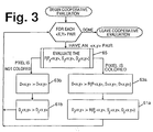
Flowchart
In this model there are six operands, three filter operands,
PF, SF, DF, and three raster operands, P, S, and D. Given these six
operands, a filter operation F, and a raster operation R,
Algorithm 3 described in the flowchart in Figure 3 shows the
evaluation model. Specifically, the filter operations 61a and 61b
determine which pixels in D are changed, and the raster operations
63a and 63b describe the change to D. In Figure 3, Since DF must be
generated from the colored and colorless input raster graphics
data according to the raster operation, the raster operation is
also used to update DF. In this model, only DF and D need initial
values. DF is initialized to colorless and D is initialized to 0.
Example
To demonstrate the algorithm, one may use the same data as
the erroneous example. Recalling Table 3, there is a source S
which is (C, M, 0), a pattern P which is (CMY, 0, CMY), and a
destination D which is (Y, Y, Y). From this one can write S
F as
110
", P
F as
101
", and D
F as
111
". Since the transparency mode is TO, let F be
SF
". That is F is
the opposite of the logical operation
∼S
" that represents a
transparent source and an opaque pattern with a filter as input
rather than the source itself.
Since F is S
F, the colored pixels due to the filter operation
are the first two. Applying the raster operation
to the first two pixels and preserving D for the third pixels
yields (C, 0, Y) as desired. Also note that the first two pixels
of D
F must be updated and this results in a new D
F. value of
101
".
In Algorithm 3 (see Figure 3), a filter is used to produce
the effect of transparency while the raster operation describes
the effect of non-transparent operations. This mechanism employs
the filter operation 65 as an input into the algorithm. Hence, one
algorithm serves all modes of transparency. The difficulty is the
creation of the filter and the determination of the filter
operation. The method has been shown for filter creation
explicitly in Algorithm 2. It has also been demonstrated how to
construct a filter operation using a logic table. The filter
operations suitable for the traditional four transparency modes
are shown below:
- OO:
- 1 (or always colored)
- OT:
- ∼SF | PF
- TO:
- SF
- TT:
- SF & PF
These filter operations when used with Algorithm 3 yield the
same results as equations [7] [8] [9], and [10].
Use With Non-Traditional Transparency Modes
Consider the desire to fill portions of D that do not have
color with a raster operation. This can be achieved using a filter
operation of ∼DF and Algorithm 3. This can not be done with the
traditional model.
In order to achieve this, DF must be constructed along with D.
This is done by applying the raster operation to the three filter
operands to produce the destination filter. The destination filter
is subject to the same transparency effects are the pattern,
source, and destination.
Hardware Implementation
The cooperative filter and raster operation evaluation model
is very efficient for software implementation when compared to
traditional solutions. Additionally, it has a significant
advantage for hardware implementation. This advantage is even
greater for devices with real-time constraints such as color and
monochrome laser printers. Before discussing these advantages, a
circuit for a three operand model is introduced.
Generalized Hardware Circuit
The generalized form of a three operand hardware circuit
diagram will now be described with reference to Figure 4. This
diagram is an implementation of Algorithm 3. In the hardware
circuit, all three logical operations can be performed in
parallel. These operations are contained in the two raster
operation logic units 71 and 73 and in the filter operation logic
unit 75. Each of these units recognizes 256 distinct operation
codes that determine the compound logical operation to perform.
The operation code informs the unit what the result for the eight
binary combinations of the three input operands should be. The
outputs of these three units are synchronized on a pixel basis.
The first raster operation unit computes the result of the
raster operation applied to the raster graphics data of the
pattern, source, and destination. The second raster operation unit
computes the result of the raster operation applied to the filters
for the pattern, source, and destination.
The filter operation unit emits
1
" if the result for a pixel
is colored according to the filter operation and
0
" otherwise.
The outputs of the three operation units are input into
multiplexors referred to as
selection units 81 and 83. Selection
is based upon the output of the filter
operation logic unit 75.
Selection Unit 1 chooses between the result of Raster
Operation
Logic Unit 1 and operand
D. Selection Unit 2 chooses between the
result of Raster
Operation Logic Unit 2 and operand D
F. The
outputs of the selection units are the new values for the
destination (D') and destination filter (D
F'). These outputs of the
selection units replace the respective pixels in the destination
raster graphics data and the destination filter.
Table 8 lists the major advantages of the cooperative filter
and raster operation model as compared to the traditional model.
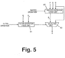
Preferred Hardware Circuit
It should be noted that a model has been described which
generalizes the notion of transparency by use of filters over
three operands. Like raster operations, this model is extensible
to any number of arguments in a trivial fashion. In the preferred
embodiment, two is chosen because the devices the preferred
circuit operates on are typically printing and display devices.
Since the applications used to generate data input to these
devices normally employ transparency only upon patterns and
sources, the preferred embodiment only includes these. This is
shown in Figure 5.
Since the destination filter is not included in the preferred
embodiment, i.e., the filter operation only accepts two operands,
the maintenance of the destination filter is unnecessary in the
preferred circuit. So, raster operation logic unit 87 is present,
but the second raster operation logic unit is not present, and the
inputs and outputs associated with filter operation logic unit 75
which results in are eliminated which results in filter operation
logic unit 91. Selection unit 93 is a multiplexor like selection
unit 1 or selection unit 2 (elements 81 and 83) in Figure 4.
This model provides for 16 filter operations. To determine
the filter operation, construct a table of the possible
combinations of two operands as shown in Table 9. This table is
much like the table for three operands in Table 7. Table 9 has
four columns which represent the four possible combinations of
pixels from two, pattern and source, filters.
For example, suppose the desired filter is
only apply the
raster operation to pixels that correspond to colored source
pixels.
" This uses the first and third columns, from the left, in
the table:
11
" and
01
". One can write these as
This is equivalent to
S
" which is a sufficient filter
operation for transparency mode TO.
The present invention provides a novel approach to
simultaneously handling transparency operatives along with raster
operations in a graphics environment. This is achieved by
introducing filters and filter operations. These are used to
determine the effect of transparency separately from the
evaluation of raster operations. This is significantly different
than traditional prior art approaches which attempt to combine
these two forms of logic into a single operation.
Algorithm 3 is defined which is a cooperative evaluation
model for filters and raster operations. These operations may be
computed independently of one another. The cooperation lies in the
fact that the results of both are used together to determine the
final result. In fact, the result of the filter operation
determines what value is output, whereas the raster operation
provides one of the values that may be output.
The invented model generalizes transparency via filter
operations to any number of operands, preferably all operands that
may affect the destination. This is in contrast to traditional
models which only consider a subset of the operands as
transparency factors. Further, the invented model is such that one
algorithm handles all cases. This is because the transparency or
filter operation is a logic operation input to the algorithm. This
is significantly different than traditional approaches which
customize an algorithm for each transparency mode.
As a consequence of the invented model and given a fired set
of inputs and two destination outputs, raster and filter, it is
possible to specify a general purpose circuit which may handle any
filter and raster operation pair. This diagram is shown for three
inputs in Figure 3. Because the preferred embodiment is the
current display and printer environment, and because the
applications which provide inputs to these typically only use
source and pattern transparency, a preferred embodiment is shown
in Figure 4 that allows three raster graphics operands and two
filters. Should the application environment of the future
generalize transparency as described herein, the invented approach
is well and uniquely suited to support that generalization as
well.