EP0816976A2 - PCI expansion card retainer clip - Google Patents
PCI expansion card retainer clip Download PDFInfo
- Publication number
- EP0816976A2 EP0816976A2 EP97110433A EP97110433A EP0816976A2 EP 0816976 A2 EP0816976 A2 EP 0816976A2 EP 97110433 A EP97110433 A EP 97110433A EP 97110433 A EP97110433 A EP 97110433A EP 0816976 A2 EP0816976 A2 EP 0816976A2
- Authority
- EP
- European Patent Office
- Prior art keywords
- panel
- opening
- clip
- cover
- card
- Prior art date
- Legal status (The legal status is an assumption and is not a legal conclusion. Google has not performed a legal analysis and makes no representation as to the accuracy of the status listed.)
- Granted
Links
Images


Classifications
-
- G—PHYSICS
- G06—COMPUTING; CALCULATING OR COUNTING
- G06F—ELECTRIC DIGITAL DATA PROCESSING
- G06F1/00—Details not covered by groups G06F3/00 - G06F13/00 and G06F21/00
- G06F1/16—Constructional details or arrangements
- G06F1/18—Packaging or power distribution
- G06F1/183—Internal mounting support structures, e.g. for printed circuit boards, internal connecting means
- G06F1/185—Mounting of expansion boards
-
- G—PHYSICS
- G06—COMPUTING; CALCULATING OR COUNTING
- G06F—ELECTRIC DIGITAL DATA PROCESSING
- G06F1/00—Details not covered by groups G06F3/00 - G06F13/00 and G06F21/00
- G06F1/16—Constructional details or arrangements
- G06F1/18—Packaging or power distribution
- G06F1/183—Internal mounting support structures, e.g. for printed circuit boards, internal connecting means
- G06F1/184—Mounting of motherboards
-
- G—PHYSICS
- G06—COMPUTING; CALCULATING OR COUNTING
- G06F—ELECTRIC DIGITAL DATA PROCESSING
- G06F1/00—Details not covered by groups G06F3/00 - G06F13/00 and G06F21/00
- G06F1/16—Constructional details or arrangements
- G06F1/18—Packaging or power distribution
- G06F1/183—Internal mounting support structures, e.g. for printed circuit boards, internal connecting means
- G06F1/186—Securing of expansion boards in correspondence to slots provided at the computer enclosure
-
- H—ELECTRICITY
- H05—ELECTRIC TECHNIQUES NOT OTHERWISE PROVIDED FOR
- H05K—PRINTED CIRCUITS; CASINGS OR CONSTRUCTIONAL DETAILS OF ELECTRIC APPARATUS; MANUFACTURE OF ASSEMBLAGES OF ELECTRICAL COMPONENTS
- H05K7/00—Constructional details common to different types of electric apparatus
- H05K7/14—Mounting supporting structure in casing or on frame or rack
- H05K7/1401—Mounting supporting structure in casing or on frame or rack comprising clamping or extracting means
- H05K7/1402—Mounting supporting structure in casing or on frame or rack comprising clamping or extracting means for securing or extracting printed circuit boards
- H05K7/1405—Mounting supporting structure in casing or on frame or rack comprising clamping or extracting means for securing or extracting printed circuit boards by clips or resilient members, e.g. hooks
Definitions
- This invention relates to a new and improved PCI expansion card retainer clip. More particularly, the invention relates to a retainer which engages a cover fixed to such card, retaining the cover in place blocking an opening formed in a wall of the computer enclosure.
- PCI cards conventionally have been sold with a vertical cover or plate along one edge having an outward extending tab.
- the cover blocks an I/O opening in the wall of the casing.
- Conventionally a screw has been used to attach a tab on the cover to a bracket on the enclosure.
- the present invention provides a retainer for the cover which does not require use of such a screw or equivalent fastener.
- the present invention comprises a removable retainer attached to a panel of a computer enclosure.
- a conventional PCI card or a blanking cover (used when no card is installed) may be installed or removed in an opening in a panel of the enclosure.
- the clip When the clip is in operative position, the card or blanking cover is secured in place.
- Use of the cover shields against EMI and dust and is a safety precaution.
- Another feature of the invention is that heretofore the outer end of the tab attached to the plate has been connected to the computer panel, which requires that the edge of the card be spaced from the panel a distance approximately equal to the length of the tab (which for practical purposes is approximately 1/2").
- the present invention enables the card to be located closer to the panel, the tab projecting outwardly of the housing and thereby making more of the space within the enclosure usable.
- a further feature of the invention is that conventionally there are two openings in the panel of the computer enclosure to accommodate two separate cards and the clip of the present invention retains the covers for both openings. Where only one or no cards are used, blocking covers are used and the present invention can retain both a card cover and a blocking cover, two card covers or two blanking covers.
- a hole must be formed in the panel adjacent the I/O openings.
- the retainer of the present invention has means for filling this hole as the retainer is moved to a closed position.
- the present invention provides means for attaching the retainer to the panel of the enclosure firmly on all axes.
- Another feature of the invention is the ease with which the user may move the clip between operative and inoperative positions.
- the retainer of the present invention comprises a spring clip formed with a plate which blocks a hole formed in the enclosure panel. Fingers projecting from an edge of the plate engage the outside of the panel and also engage and hold in place the covers, either of the PCI cards or the blanking covers are used when no cards are employed.
- the plate also has outward bent tabs which fit through openings in the panel.
- a resilient portion having two leaves which normally diverge outwardly, but which may be gripped by the fingers of the user to compress the leaves into approximately parallel position. Tabs on one of the leaves fit through apertures in the panel of the enclosure.
- the clip is held in position on the panel and the card covers secured in place.
- the spring clip is compressed, releasing the tabs from the holes in the side panel and permitting the clip to be removed from a position engaging the card covers.
- the mechanism of the present invention is actuated with the cover of the enclosure off, inasmuch as the clip is disengageable only from the inside of the enclosure. Hence, any lock which is embodied for the enclosure cover improves the security of the device.
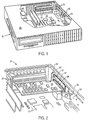
- FIG. 1 is a perspective view of a computer enclosure with the cover broken away to reveal internal construction. In FIG. 1, no PCI card is installed, but the openings in the enclosure therefor are closed by removable blanking covers.
- FIG. 2 is an enlarged perspective view of a portion of the structure of FIG. 1.
- one PCI card is installed in the enclosure.
- FIG. 3 is an enlarged side elevational view of a portion of the panel of the computer construction showing two cards installed and the retainer clip in place.
- FIG. 4 is a view similar to FIG. 3 showing a step in the removal of the clip.
- FIG. 5 is a view similar to FIG. 3 showing one of the PCI cards in the process of being removed.
- FIG. 6 is an enlarged perspective view showing the retainer.
- FIG. 7 is a perspective view of the structure of FIG. 6 viewed from an opposite angle.
- Enclosure 21 has a bottom 22 and top 23 and at least one vertical panel 24. Various electronic components 26 may be installed on bottom 22. Adjacent rear panel 24 are two horizontally spaced apart connectors 27 of a type well known in the industry. The PCI cards 36 hereinafter described are plugged into the connectors 27. However, as shown in FIG. 1, no cards are installed. Accordingly, blanking covers 31 are used to close off openings 46 in panel 24, there being two such covers 31 shown, each having a tongue 32 and an outwardly protruding tab 33. In FIG. 2, one of the blanking covers 31 is removed and a PCI card 36 is installed in lower connector 27.
- PCI card 36 is of a type well known in the industry. Technical specifications of such cards are set forth in a publication entitled: PCI Local Bus Specification, Rev.2.0, Chapter 5, Mechanical Specification , published by PCI Special Interest Group of Hillsboro, OR.
- One longitudinal edge of card 36 is connected to one of the connectors 27.
- a lateral edge of card 36 is formed with an edge reinforcement 37 and externally thereof is a metallic cover 38.
- Cover 38 has an extending tongue 39 at one end and a laterally outwardly bent tab 33 at its opposite end.
- a screw (not shown) is used to connect the tab 33 to a bracket (also not shown) on the interior of panel 24.
- the present invention eliminates the necessity for use of the screw or similar means of attachment.
- Elongated rectangular openings 46 are formed in panel 24, of a length slightly greater than the distance required to disconnect the contacts (not shown) on card 36 from connector 27. Where no PCI card is used, blanking covers 31 are used to close such openings and when cards 36 are used, the covers 38 close such openings. Adjacent one end of opening 46 is a tongue receptor 47 which receives tongue 39 and holds it in place. Inward projecting cover edge guides 48 are positioned above and below the longitudinal edges of openings 46 to engage the top and bottom edges of cover 38 (or 31).
- Rearward of openings 46 is vertically elongated rectangular opening 49 which is used to facilitate insertion and removal of card 36 where the enclosure top 23 is closed and when the present invention is not employed.
- Clip 56 is formed with a substantially rectangular plate 57 which is of a size to close off the opening 49.
- An edge of plate 57 has upper and lower outside fingers 58 which fit through opening 49 and engage the exterior of panel 24.
- On the same edge of plate 57 are inside fingers 59 which engage the ends of covers 38 (or 31) opposite tongues 39.
- Plate 57 also has outwardly struck tabs 61 which fit through opening 49 and engage protrusions 62 into opening 49. The tabs 61 prevent retraction movement of plates 57 relative to panel 24.
- Bent approximately at right angles to the edge of plate 57 opposite fingers 58 and 59 is an inward projecting leaf 66 which is formed at its inner end with a bend 67 from which is a return leaf 68 which in the relaxed position of the clip diverges from projection 66.
- Finger grip 69 may be fixed to return 68 in order to assist in gripping the same.
- the distal edges of return leaf 68 are formed with tabs 71 which may be inserted in holes 72 in panel 24 as hereinafter explained.
- tongues 39 are inserted in receptors 47 and cards 36 are plugged into connectors 27 with the tabs 33 extending outwardly of panel 24 through openings 46.
- the user then installs the plate 57 in position with finger 58 on the exterior of the panel 24 and fingers 59 engaging the nearest end of covers 38 (or blanking covers 31) and also inserts the tabs 61 through opening 49.
- the user then squeezes the clip 56 by placing a thumb or finger on the grip 69 and other fingers on the leaf 66 so that the tabs 71 may be inserted in the hole 72.
- the clip Upon release of the grip, the clip remains attached to the panel 24 and the covers 38 or 31 are firmly held in place along all axes.
Abstract
Description
Claims (11)
- A computer enclosure panel (24) formed with a first opening (46) having a first opening end and a second opening end, a cover (31,38) shaped to close said first opening (46) having a first cover end (39) and a second cover end (39), first means (47) adjacent said first opening end for securing said first cover end (39) to said panel (24), second means (56) movable between a first position adjacent said second opening end to retain said second cover end (33) to said panel (24) and a second position remote from said second cover end (33), said second means comprising a clip (56) having panel engaging means (71), resilient means (66) biasing said panel engaging means (71) in a first direction, said clip (56) being compressible to move said panel engaging means (71) in a second direction opposite said first direction, said panel (24) being formed with means (72) to receive said panel engaging means (71) when said clip (56) is compressed in said second direction and to retain said clip (56) attached to said panel (24) when said clip (56) is released and said panel engaging means (71) moves in said first direction.
- The panel of claim 1, which further comprises a card, preferably a PCI card (36), said card (36) being secured to said cover (38).
- The panel of claim 1, in which said panel (24) is formed with a second opening (49) adjacent said first-mentioned opening (46), said clip (56) having a blanking portion (57) closing said second opening (49) when said second means (56) is in first position.
- The panel of any of the preceding claims, in which further comprises at least one finger (58) on said second means (56) extending through said opening (46) and engaging said panel (24) when said second means (56) is in first position.
- The panel of any of the preceding claims, which further comprises at least one finger (59) on said second means (56) engaging said cover (31,38) when said second means (56) is in first position.
- The panel of any of the preceding claims, in which said panel (24) is formed with a third opening parallel to and below said first-mentioned opening (46), a second cover (38) having a third cover end and a fourth cover end shaped to close said third opening, third means (47) adjacent said first opening end for securing said third cover end to said panel (24), said second means (56) retaining said fourth cover end to said panel (24) when said second means (56) is in first position.
- The panel of claim 3, in which said clip (56) comprises a plate (57), a first spring leaf (66) extending from said plate (57), a second spring leaf (68) disposed at an acute angle relative to said first spring leaf (66), means (67) resiliently connecting said leaves (66,68) together, said plate (57) having first panel engaging means (58), said second spring leaf (68) having second panel engaging means (71), said panel (24) having at least one aperture (72) to receive said second engaging means (71), whereby said spring leaves (66,68) are squeezed together said first and second panel engaging means (58,71) may be installed in said second opening (49) and said aperture (72), respectively, said first and second panel engaging means (58,71) securing said clip (56) to said panel (24) when said spring leaves (66,68) are released.
- The panel of claim 7, in which said means resiliently connecting said leaves together comprises a bend (67), said plate (57), said leaves (66,68) and said bend (67) being integral.
- The panel of claim 7, in which said first panel engaging means comprises at least one finger (58) on said plate (57) which extends out through said opening (49) and engages the exterior of said panel (24).
- The panel of claim 7, in which said second panel engaging means comprises a bent tab (71) extending through said aperture (72) and engaging the exterior of said panel (24).
- The panel of claim 7, in which said panel (24) is formed with an enlarged second opening adjacent said first-mentioned opening (46), said plate blocking said second opening (46), said first panel engaging means (58) extending through said second opening (46).
Applications Claiming Priority (2)
| Application Number | Priority Date | Filing Date | Title |
|---|---|---|---|
| US08/675,281 US5640309A (en) | 1996-07-01 | 1996-07-01 | PCI expansion card retainer clip |
| US675281 | 1996-07-01 |
Publications (3)
| Publication Number | Publication Date |
|---|---|
| EP0816976A2 true EP0816976A2 (en) | 1998-01-07 |
| EP0816976A3 EP0816976A3 (en) | 1998-05-13 |
| EP0816976B1 EP0816976B1 (en) | 2002-03-06 |
Family
ID=24709796
Family Applications (1)
| Application Number | Title | Priority Date | Filing Date |
|---|---|---|---|
| EP97110433A Expired - Lifetime EP0816976B1 (en) | 1996-07-01 | 1997-06-25 | PCI expansion card retainer clip |
Country Status (3)
| Country | Link |
|---|---|
| US (1) | US5640309A (en) |
| EP (1) | EP0816976B1 (en) |
| DE (1) | DE69710816T2 (en) |
Families Citing this family (37)
| Publication number | Priority date | Publication date | Assignee | Title |
|---|---|---|---|---|
| KR200266864Y1 (en) * | 1996-07-16 | 2002-05-09 | 윤종용 | Board connection structure |
| US6078504A (en) * | 1997-10-08 | 2000-06-20 | Cisco Systems, Inc. | Universal adapter bracket for communications devices |
| US6185093B1 (en) * | 1997-11-12 | 2001-02-06 | Dell, Usa, L. P. | Expansion card carrier and method for a computer system |
| US5947571A (en) * | 1998-01-06 | 1999-09-07 | Ho; Hsin Chien | Device adapted to position interface cards |
| US6058025A (en) * | 1998-04-21 | 2000-05-02 | International Business Machines Corporation | Computer tailgate having expansion slot alignment pins |
| US6390320B2 (en) * | 1998-04-29 | 2002-05-21 | Cisco Technology, Inc. | Easily installable and removable electro-magnetic interference shielding faceplate |
| US6220887B1 (en) | 1998-09-28 | 2001-04-24 | Enclosure Technologies, Inc. | Stabilizer for holding circuit boards in a port |
| TW395572U (en) * | 1998-10-06 | 2000-06-21 | Hon Hai Prec Ind Co Ltd | Shielding structure of electronic device |
| US6408347B1 (en) | 1998-12-10 | 2002-06-18 | Cisco Technology, Inc. | Integrated multi-function adapters using standard interfaces through single a access point |
| US6215668B1 (en) | 1999-03-23 | 2001-04-10 | Dell Usa, L.P. | Expansion card retaining device |
| US6256191B1 (en) | 1999-05-18 | 2001-07-03 | Dell Usa, L.P. | Card retention apparatus for a computer system |
| US6278614B1 (en) | 1999-05-21 | 2001-08-21 | International Business Machines Corporation | Expansion card retention apparatus and method |
| FR2794256A1 (en) * | 1999-05-27 | 2000-12-01 | E2A Technology Sa | Device for blocking computer card position in computer chassis has clip that comes by pivoting of bolt with elastic support against limbs of connectors, in inserting of clip into aperture |
| US6046912A (en) * | 1999-06-03 | 2000-04-04 | Micron Electronics, Inc. | Computer system having riser board expansion capability |
| TW438201U (en) * | 1999-09-23 | 2001-05-28 | Hon Hai Prec Ind Co Ltd | Computer case body |
| US6487089B1 (en) * | 2000-03-20 | 2002-11-26 | International Business Machines Corporation | Enhanced arrangement for securing two mating components together |
| US6639807B1 (en) | 2000-04-10 | 2003-10-28 | Sun Microsoft, Inc. | Card retention mechanism |
| US6674650B1 (en) | 2000-06-16 | 2004-01-06 | Gateway, Inc. | Card retention assembly |
| US6442038B1 (en) | 2000-08-11 | 2002-08-27 | Gateway, Inc. | Expansion card hold down assembly |
| US6418010B1 (en) | 2000-08-11 | 2002-07-09 | Gateway, Inc. | Convertible flat panel display hanging support |
| TW486232U (en) * | 2000-09-29 | 2002-05-01 | Hon Hai Prec Ind Co Ltd | Fastening device for computer expansion card |
| US6404651B1 (en) | 2000-11-27 | 2002-06-11 | International Business Machines Corporation | Computer expansion card shield retention device |
| US6454581B1 (en) | 2000-12-28 | 2002-09-24 | Spx Corporation | Plug for covering a plurality of openings of an electronic device |
| US6612460B2 (en) * | 2000-12-28 | 2003-09-02 | Spx Corporation | Plug for covering an opening of an electronic device |
| DE20109095U1 (en) * | 2001-05-31 | 2002-10-02 | Faist Systeme Gmbh | Mounting adapter for low-profile computer cards |
| US20030049948A1 (en) * | 2001-09-13 | 2003-03-13 | Kim David J. | Apparatus and method for coupling buses |
| US6625034B2 (en) * | 2001-11-15 | 2003-09-23 | Gateway, Inc. | Pivoting pressure cover |
| FR2840505A1 (en) * | 2002-05-31 | 2003-12-05 | Thomson Multimedia Broadband F | SHIELDING DEVICE FOR PRINTED CIRCUIT BOARDS |
| US6937467B2 (en) * | 2003-08-27 | 2005-08-30 | Inventec Corporation | Device for fastening adapter cards at a positioning frame of computer case |
| CN2681189Y (en) * | 2003-12-23 | 2005-02-23 | 鸿富锦精密工业(深圳)有限公司 | Expansion card fixing device |
| US7254041B2 (en) * | 2005-12-30 | 2007-08-07 | Hong Fu Jin Precision Industry (Shenzhen) Co., Ltd. | Expansion card mounting apparatus |
| US8144463B2 (en) | 2010-04-08 | 2012-03-27 | Dell Products L.P. | Card retention system |
| TWI408532B (en) * | 2010-11-17 | 2013-09-11 | Giga Byte Tech Co Ltd | Computer case |
| CN103376851A (en) * | 2012-04-27 | 2013-10-30 | 鸿富锦精密工业(深圳)有限公司 | Fixing device for expansion card |
| US9166337B2 (en) * | 2012-12-18 | 2015-10-20 | Nvidia Corporation | Externally latching I/O housing |
| CN110908468B (en) * | 2019-11-22 | 2021-08-20 | 苏州浪潮智能科技有限公司 | PCIE card fixing device |
| CN115793789A (en) * | 2021-09-10 | 2023-03-14 | 英业达科技有限公司 | Baffle combination |
Citations (4)
| Publication number | Priority date | Publication date | Assignee | Title |
|---|---|---|---|---|
| EP0666524A2 (en) * | 1994-02-08 | 1995-08-09 | Vobis Microcomputer Ag | Personal computer with housing, mother board, plug-in cards, and related retaining device |
| DE29510599U1 (en) * | 1995-06-29 | 1995-11-16 | Siemens Nixdorf Inf Syst | Covering device for installation spaces accessible through openings in a housing wall of a data processing device for standard flat assemblies that can be used there |
| DE29604610U1 (en) * | 1996-03-12 | 1996-07-11 | Siemens Nixdorf Inf Syst | Holding device for the mounting bracket of plug-in cards or standard flat modules |
| US5601349A (en) * | 1995-07-25 | 1997-02-11 | Dell U.S.A., Lp | Captive latch mechanism for use with an expansion card cage in a personal computer |
Family Cites Families (4)
| Publication number | Priority date | Publication date | Assignee | Title |
|---|---|---|---|---|
| FR2598689B1 (en) * | 1986-05-13 | 1988-09-02 | Francaise Metallurg | PRESENTATION AND STORAGE BOX OF AN ELECTRIC TOOL, SUCH AS A MINI-DRILL |
| US5004867A (en) * | 1988-11-14 | 1991-04-02 | Compuadd Corporation | Personal computer expansion slot seal and method |
| US4979075A (en) * | 1989-10-12 | 1990-12-18 | Compuadd, Corporation | Method and apparatus for controlling circuit expansion for consumer electronic systems |
| US5544006A (en) * | 1995-01-18 | 1996-08-06 | Dell Usa, L.P. | Computer chassis having flexible card guide for expansion card insertion and removal |
-
1996
- 1996-07-01 US US08/675,281 patent/US5640309A/en not_active Expired - Fee Related
-
1997
- 1997-06-25 DE DE69710816T patent/DE69710816T2/en not_active Expired - Fee Related
- 1997-06-25 EP EP97110433A patent/EP0816976B1/en not_active Expired - Lifetime
Patent Citations (4)
| Publication number | Priority date | Publication date | Assignee | Title |
|---|---|---|---|---|
| EP0666524A2 (en) * | 1994-02-08 | 1995-08-09 | Vobis Microcomputer Ag | Personal computer with housing, mother board, plug-in cards, and related retaining device |
| DE29510599U1 (en) * | 1995-06-29 | 1995-11-16 | Siemens Nixdorf Inf Syst | Covering device for installation spaces accessible through openings in a housing wall of a data processing device for standard flat assemblies that can be used there |
| US5601349A (en) * | 1995-07-25 | 1997-02-11 | Dell U.S.A., Lp | Captive latch mechanism for use with an expansion card cage in a personal computer |
| DE29604610U1 (en) * | 1996-03-12 | 1996-07-11 | Siemens Nixdorf Inf Syst | Holding device for the mounting bracket of plug-in cards or standard flat modules |
Also Published As
| Publication number | Publication date |
|---|---|
| US5640309A (en) | 1997-06-17 |
| EP0816976B1 (en) | 2002-03-06 |
| DE69710816D1 (en) | 2002-04-11 |
| DE69710816T2 (en) | 2002-10-31 |
| EP0816976A3 (en) | 1998-05-13 |
Similar Documents
| Publication | Publication Date | Title |
|---|---|---|
| US5640309A (en) | PCI expansion card retainer clip | |
| US5673175A (en) | PCI expansion card double-door retainer | |
| US5748453A (en) | PCI expansion card slide-type retainer | |
| US6595605B1 (en) | Spring loaded latching for system enclosure panels | |
| EP1653264B1 (en) | Optical connector with shutter | |
| US6185103B1 (en) | Releasable disk drive for electronic devices | |
| TWI690795B (en) | Fixing mechanism and related electronic apparatus | |
| US5601349A (en) | Captive latch mechanism for use with an expansion card cage in a personal computer | |
| US7753458B2 (en) | Expansion card mounting apparatus | |
| US6025987A (en) | Mounting arrangement for mounting a subsystem unit | |
| US6972370B2 (en) | Mounting device for mounting expansion cards in computer enclosure | |
| US20070222347A1 (en) | Mounting assembly for side panel of computer enclosure | |
| JP3638535B2 (en) | Card holding assembly and chassis using the same | |
| US20050078445A1 (en) | Mounting apparatus for storage device | |
| US20050111179A1 (en) | Mounting device for mounting expansion cards in computer enclosure | |
| US6654238B2 (en) | Fastening device for securing a data storage device | |
| US6401311B1 (en) | Retaining clip for computer expansion card | |
| US5478246A (en) | Guiding and protecting housing for memory card connector | |
| US6582132B1 (en) | Connector panel mount system | |
| US6404651B1 (en) | Computer expansion card shield retention device | |
| US10666308B2 (en) | Communication-adapter mounting device | |
| CN213522617U (en) | SD card cover and shell | |
| KR100433513B1 (en) | Notebook computer hdd assembly having improved structure facilitating attachment | |
| CN216204192U (en) | Electrical component and air conditioner with same | |
| US6681939B2 (en) | Fixing device for attaching an auxiliary card in a personal computer |
Legal Events
| Date | Code | Title | Description |
|---|---|---|---|
| PUAI | Public reference made under article 153(3) epc to a published international application that has entered the european phase |
Free format text: ORIGINAL CODE: 0009012 |
|
| AK | Designated contracting states |
Kind code of ref document: A2 Designated state(s): DE FR GB |
|
| PUAL | Search report despatched |
Free format text: ORIGINAL CODE: 0009013 |
|
| AK | Designated contracting states |
Kind code of ref document: A3 Designated state(s): AT BE CH DE DK ES FI FR GB GR IE IT LI LU MC NL PT SE |
|
| 17P | Request for examination filed |
Effective date: 19981104 |
|
| AKX | Designation fees paid |
Free format text: DE FR GB |
|
| RBV | Designated contracting states (corrected) |
Designated state(s): DE FR GB |
|
| 17Q | First examination report despatched |
Effective date: 20000704 |
|
| GRAG | Despatch of communication of intention to grant |
Free format text: ORIGINAL CODE: EPIDOS AGRA |
|
| GRAG | Despatch of communication of intention to grant |
Free format text: ORIGINAL CODE: EPIDOS AGRA |
|
| GRAH | Despatch of communication of intention to grant a patent |
Free format text: ORIGINAL CODE: EPIDOS IGRA |
|
| GRAH | Despatch of communication of intention to grant a patent |
Free format text: ORIGINAL CODE: EPIDOS IGRA |
|
| REG | Reference to a national code |
Ref country code: GB Ref legal event code: IF02 |
|
| GRAA | (expected) grant |
Free format text: ORIGINAL CODE: 0009210 |
|
| AK | Designated contracting states |
Kind code of ref document: B1 Designated state(s): DE FR GB |
|
| REF | Corresponds to: |
Ref document number: 69710816 Country of ref document: DE Date of ref document: 20020411 |
|
| ET | Fr: translation filed | ||
| PLBE | No opposition filed within time limit |
Free format text: ORIGINAL CODE: 0009261 |
|
| STAA | Information on the status of an ep patent application or granted ep patent |
Free format text: STATUS: NO OPPOSITION FILED WITHIN TIME LIMIT |
|
| 26N | No opposition filed |
Effective date: 20021209 |
|
| PGFP | Annual fee paid to national office [announced via postgrant information from national office to epo] |
Ref country code: FR Payment date: 20040608 Year of fee payment: 8 |
|
| PGFP | Annual fee paid to national office [announced via postgrant information from national office to epo] |
Ref country code: DE Payment date: 20050623 Year of fee payment: 9 |
|
| PG25 | Lapsed in a contracting state [announced via postgrant information from national office to epo] |
Ref country code: FR Free format text: LAPSE BECAUSE OF NON-PAYMENT OF DUE FEES Effective date: 20060228 |
|
| REG | Reference to a national code |
Ref country code: FR Ref legal event code: ST Effective date: 20060228 |
|
| PGFP | Annual fee paid to national office [announced via postgrant information from national office to epo] |
Ref country code: GB Payment date: 20060621 Year of fee payment: 10 |
|
| PG25 | Lapsed in a contracting state [announced via postgrant information from national office to epo] |
Ref country code: DE Free format text: LAPSE BECAUSE OF NON-PAYMENT OF DUE FEES Effective date: 20070103 |
|
| GBPC | Gb: european patent ceased through non-payment of renewal fee |
Effective date: 20070625 |
|
| PG25 | Lapsed in a contracting state [announced via postgrant information from national office to epo] |
Ref country code: GB Free format text: LAPSE BECAUSE OF NON-PAYMENT OF DUE FEES Effective date: 20070625 |