EP0814577A1 - Interface unit for a mobile radio communication network - Google Patents
Interface unit for a mobile radio communication network Download PDFInfo
- Publication number
- EP0814577A1 EP0814577A1 EP97401358A EP97401358A EP0814577A1 EP 0814577 A1 EP0814577 A1 EP 0814577A1 EP 97401358 A EP97401358 A EP 97401358A EP 97401358 A EP97401358 A EP 97401358A EP 0814577 A1 EP0814577 A1 EP 0814577A1
- Authority
- EP
- European Patent Office
- Prior art keywords
- channel
- received
- message
- code
- rank
- Prior art date
- Legal status (The legal status is an assumption and is not a legal conclusion. Google has not performed a legal analysis and makes no representation as to the accuracy of the status listed.)
- Withdrawn
Links
Images


Classifications
-
- H—ELECTRICITY
- H04—ELECTRIC COMMUNICATION TECHNIQUE
- H04B—TRANSMISSION
- H04B1/00—Details of transmission systems, not covered by a single one of groups H04B3/00 - H04B13/00; Details of transmission systems not characterised by the medium used for transmission
- H04B1/69—Spread spectrum techniques
- H04B1/707—Spread spectrum techniques using direct sequence modulation
-
- H—ELECTRICITY
- H04—ELECTRIC COMMUNICATION TECHNIQUE
- H04B—TRANSMISSION
- H04B7/00—Radio transmission systems, i.e. using radiation field
- H04B7/24—Radio transmission systems, i.e. using radiation field for communication between two or more posts
- H04B7/26—Radio transmission systems, i.e. using radiation field for communication between two or more posts at least one of which is mobile
- H04B7/2628—Radio transmission systems, i.e. using radiation field for communication between two or more posts at least one of which is mobile using code-division multiple access [CDMA] or spread spectrum multiple access [SSMA]
Definitions
- the present invention relates generally to a telecommunications network.
- the invention applies to a terrestrial network for communications with mobiles or to a satellite network for communications with mobiles.
- the ETSI GSM Recommendations define a technical solution for implementing a cellular radiocommunication network with combined TDMA / FDMA type mobiles.
- the choice concerning the technique or the combination of transmission techniques have a direct implication on the realization, not only of the transmission units proper, namely terminals and base stations, but also of the entire mobile network, excluding stations based.
- a large part of the entire infrastructure is defined according to the choice which is made for the transmission technique.
- This solution has the disadvantage of costly developments for each type of network developed, by obliging operators to make significant systematic developments for each type of transmission technique chosen. As a corollary, this then leads to less reliability of each developed network and less controlled maintenance for each network.
- the invention aims to remedy this drawback by providing a unit allowing the reuse of a large part of the existing network infrastructures using a given transmission technique for the development of new networks using another transmission technique.
- the first means for associating associate, in addition, with each message received, as a function of the identification data, a rank of time interval (it1-it4), a transmission channel being of CDMA / TDMA type and being defined by a rank of time interval in a frame and by a coding sequence.
- the first means for associating associate with at least two distinct channel packets of the same channel respectively at least two distinct transmission channel identification information, the two identification information identifying the same rank of time interval and two respective respective coding sequences.
- the successive data messages are received from a base station controller of a G.S.M type network, to be transmitted in code division multiple access mode.
- the first means associate with each message received at least one transmission channel identification information, further depending on a transmitter / receiver identification information, known as TRX in GSM.
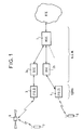
- the infrastructure of a radiocommunication network with the mobiles for implementing the invention comprises, on the one hand, a mobile service switch, or MSC, 1 connected via MIC links to the PSTN Switched Telephone Network and base station controllers 2a, 2b, assumed here of the GSM type, and, on the other hand, base stations 3, 4.
- the Mobile Service Switch is responsible for routing communications from and to mobiles in a given geographic area.
- the base station controllers 2a, 2b connected to a Mobile Service Switch are local communications switches, moreover providing a control function for one or more base stations 3, 4.
- the base stations 3, 4 provide radio transmission / reception of communications to / from mobiles 6, 7.
- a radio transmission between a base station and a mobile can be established directly, in the case of a terrestrial network, or via a relay satellite 5, in the case of a satellite network. More information on GSM networks is provided in the book "The GSM System for Mobile Communications" by Michel MOULY and Marie-Bernadette PAUTET, published by the authors, Edition 1992 as well as in the ETSI Recommendations relating to GSM.
- the invention proposes using base stations 3, 4 using an operating mode at least partially CDMA, the rest of the infrastructure, namely the base station controllers 2a, 2b and the switches of the Mobile Service 1, advantageously using the elements of existing networks, such as GSM.
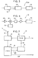
- a base station 3, 4 implementing the invention comprises a switching and message formation unit 38, a transmission chain 36, a reception chain 36 'and an antenna 37 An output of the transmit chain 36 and an input of the receive chain 36 'are coupled to the antenna 37.
- the transmission chain 36 includes M transmission queues 30-1 to 30-M whose respective outputs are applied to inputs of M code modulation units 32-1 to 32-M.
- the respective outputs of the M code modulation units 32-1 to 32-M are applied to an input of a radio transmission unit 34.
- the reception chain 36 ' comprises a radio reception unit 35, one output of which is s' applies to M code demodulation units 33-1 to 33-M, and M reception queues 31-1 to 31-M whose inputs receive the respective outputs of the M code demodulation units 33-1 to 33 -Mr.
- the routing and message formation unit 38 is coupled, on the one hand, to the M respective inputs of the queues 30-1 to 30-M through a first bus B1 and, on the other hand, to the M respective outputs of queues 31-1 to 31-1 through a second bus B2.
- This unit 38 is provided here for coupling, or interfacing, a G.S.M 2a, 2b type base station controller to the transmission and reception chains 36 and 36 ′ operating at least partially in CDMA; it is therefore located at the level defined in G.S.M by the Abis interface between G.S.M base station controller and G.S.M base station.
- the Abis interface defines a particular message format for the messages transmitted and received by a base station controller 2a, 2b.
- Each message relates to a particular channel or sub-channel and has several fields including a field identifying the type of channel conveyed "CH. TYPE", a field identifying the rank "TS-n °" of the time interval in the TDMA frame carrying this channel, and possibly the rank "SC No.” of a subchannel within a channel, and finally a useful data field "DATA”.
- Specific information identifying a "TRX" transmitter / receiver in a base station receiving a given message is carried by the LINK level, within the meaning of the ISO OSI Recommendations.
- the definition of a TRX is given on page 212 of the book "The GSM System for Mobile Communications" by Michel MOULY and Marie-Bernadette PAUTET, published by the authors, Edition 1992.
- the elementary radio data transmission support structure is called "frame".
- a frame is defined by 8 multiplexed time intervals IT0-IT7, which are repeated with the periodicity of the frame. Each time interval is intended to convey a channel or several subchannels.
- TCH traffic channels
- DCCH dedicated channels
- CCCH common control channels
- BCCH general information dissemination channels
- Certain channels for example the dedicated DCCH channels and the general information broadcasting channels BCCH each carry subchannels, such as the SACCH (Slow Associated Control CHannel) subchannels for the DCCH channels or the SCH subchannels ( Channel Synchronization) for BCCH channels.
- SACCH Small Associated Control CHannel
- SCH subchannels Channel Synchronization
- the association table 382 can associate with the aforementioned information, in addition to the rank of a queue identifying a modulation unit by given code, a rank of time interval in a frame.
- the routing unit is synchronized with the frequency of appearance of the frames and time intervals in the frame to transmit data packets in the queues 30-1 to 30-M at respective times synchronized with the instants of appearance of the temporal intervals in a frame.
- association table associates with any message whose "CH. TYPE” field identifies BCCH or CCCH channel information, a given queue , and this independently of the information conveyed in the time interval rank field. Furthermore, this same table can associate with any message whose "CH. TYPE” field identifies TCH channel information, and the "TS No.” field identifies the 7th time interval IT7, the 3rd queue.
- this association between information carried by the fields "" TS No. ",” SC No. “,” CH. TYPE “and” TRX “and the queues 30-1 to 30-M depend on the transmission resources which are allocated by the transmission chain 36.
- the total capacity will be equal to the baseband bit rate of each channel (which is modulated by a sequence Respective PN) multiplied by the number of PN sequences.
- the total capacity will be equal to the baseband bit rate d '' a channel (occupying a time interval per frame) modulated by orthogonal sequences, multiplied by the number of sequences and by the number of time intervals in a frame.
- An adequacy must exist between the total bit rate capacity to be transmitted and the transmission resources provided by the transmission chain, and the unit 38 is responsible for switching each channel to a particular resource by associating beforehand with the information conveyed. in messages received MES, identification information of transmission channels.
- association function defined by the association table 382 is given as follows: (TS-n °, SC n °, TRX) or ("CH tYPE", TS-n °, SC n °, TRX) ⁇ (PN) in CDMA transmission mode, where PN denotes a PN sequence; or by : (TS-n °, SC n °, TRX) or (TS-n °, SC n °, TRX, "CH TYPE”) ⁇ (Hm) in CDMA transmission mode, where Hm denotes one of plurality of orthogonal sequences between them, for a solution of the type described in patent US-A-5 103 459; or by: (TS-n °, SC n °, TRX) or (TS-n °, SC n °, TRX, "CH TYPE") ⁇ (Hm, ITj) in combined TDMA / CDMA mode, or Hm denotes one of 'a plurality of orthogonal
- the association data stored in the association table 382 are also used for allocating a channel to a mobile.
- a GSM channel allocated by the infrastructure to a mobile will be translated into a CDMA channel.
- a message conveying information identifying this CDMA channel will be sent to the mobile when this channel is allocated to the mobile.
- each modulation unit 32-m, m comprised between 1 and M comprises in cascade a convolutional coding circuit 320, an interleaving circuit 321, a phase modulation circuit QPSK 322, and on each of two parallel channels, two multipliers identified by the references 323 and 325 for one of the two channels, and by the references 324 and 326 for the other of the two channels.
- the baseband data packets from the 30-m queue are therefore modulated by code by the 32-m modulation circuit, then interleaved by the 321 circuit.
- the resulting interleaved signal is modulated in the QPSK phase (Quadrature Phase Shift keying) by circuit 322.
- the latter 322 produces two quadrature signal components which are each applied to the two multipliers 323, 325 and 324, 326 of the channel considered.
- the operation of the network is such that all the signals transmitted inside a cell (terrestrial networks) or of a beam (satellite networks) use the same PN (pseudo-noise) sequence which is different from a PN sequence used by a neighboring cell, or beam.
- PN pseudo-noise
- a signal to a particular station, such as terminal is further coded by a particular sequence which is orthogonal to the sequences used for signals to other stations in the same cell or the same beam.
- PN sequences consist of identical pseudo-random sequences which are time-shifted between them for separate cells.
- Orthogonal sequences are, for example, Walsh functions, also known as "Hadamard sequences”.
- the Hadamard sequences are obtained from a Hadamard matrix of rank M, M being a power of 2, such that:
- a Hadamard Hm sequence, m between 1 and M, is a respective one of the lines M of the Hadamard matrix.
- a Hadamard matrix of rank M therefore contains M sequences, each having a length of M bits.
- Hadamard sequences of order M have the property that over an interval of M symbols, the correlation between the different sequences is zero, it being understood that these different sequences are aligned in time. This results from the fact that each sequence differs from any other sequence for half of the bits which compose it.
- the two components of QPSK modulated signal in quadrature are both multiplied by a Hadamard Hm sequence of rank m and by a PN sequence associated with the base station 3, 4 considered, to produce two signals in quadrature modulated by Im and Qm code.
- the different quadrature signals Im and Qm, m between 1 and M, coming from the different code modulation units 32-1 to 32-M are added by means of adders 340, 341 and 342.
- the resulting addition signal is modulated by a transmission carrier PE before being amplified by an amplifier 344 to be transmitted through the antenna 37.
- This signal transmitted through the antenna 37, is as shown in FIG. 13. It uses for example an elementary frame pattern with four time intervals it1-it4 which are repeated at the frame frequency.
- a transmission channel in the network described here and defined by a time interval itj, j between 1 and 4, and a Hadamard Hm sequence corresponds by its content, except in special cases, to a TDMA channel in GSM.
- the BCCH traffic is carried by the channels associated with a given Hadamard sequence, such as H0.
- the association table 382 therefore performs this correspondence.
- the traffic channels In GSM, the traffic channels, called full-rate, denoted TCH / F which are received by the routing unit 38 are such that they occupy an interval of the same rank in each successive GSM frame of 8 time intervals.
- TCH / F channels advantageously, with reference to American patent US-A-5 373 502 in the name of ALCATEL.NV, the association table 382 associates with a time interval out of two a channel defined by an interval temporal itj of the frame shown in FIG. 13 and a sequence of Hadamard Hm and at the other of these two temporal intervals, the same temporal interval itj of the frame but a sequence of Hadamard Hm 'distinct from Hm.
- the TCH / F channel is received by a remote station, half coded on two distinct Hadamard sequences but over the same time interval.
- the elementary frame structure shown in FIG. 13A is part of a superframe structure made up of N elementary frames, (N-1) of these frames conveying the content of the GSM channels, and a frame conveying PN synchronization data.
- N-1 the allocation of a CDMA or CDMA / TDMA type channel combined by the association table to a GSM channel can be arbitrary, except for the BCCH and CCCH signaling channels which should preferably be modulated by the same Hadamard sequence.
- the full-rate traffic channels will be divided, for a time interval out of two, on a Hadamard sequence and for the other of these time intervals over another sequence of Hadamard, using the same time interval d ' program.
- each superframe ST comprises an acquisition sequence SS.
- the SS acquisition sequence is sent once during a given duration for each superframe produced. It is transmitted by each 32-1 to 32-M modulation unit undergoing only PN code modulation, and no modulation by Hadamard sequence.
- a remote receiving station will receive in the time interval coinciding with the sequence SS, this sequence SS with a power M times greater than the power normally received for one of the transmission channels defined in our embodiment by a time interval is a Hadamard sequence.
- the superframes thus produced are received by a receiving station 6, for example a terminal, shown in FIG. 7.
- the terminal 6 comprises a duplexer 61 which is connected to an antenna, and whose input is connected to a output of a transmitting unit 62, and an output of which is applied to an input of a receiving unit 63.
- the receiving station further comprises a central unit 64.
- the reception unit 63 of the terminal 6,7 comprises an RF amplifier 630, a multiplier 631, a carrier generator 632, a bandpass filter 633, an IF amplifier 634, an analog / converter digital 635, 3 code demodulation units 65a-65c and a delay demultiplexing circuit 636.
- the addition signal modulated by a transmission carrier PE to be transmitted through the antenna 37 by the station 2a, 2b is received by the antenna 60 of the terminal 6.
- This received modulated addition signal is amplified RF by the amplifier 630, then demodulated by the demodulation carrier produced by the generator 632, filtered bandpass in the filter 633, amplified IF in amplifier 634, then converted into a digital addition signal by converter 635.
- each code demodulation unit includes a PN / QPSK correlator 651, a phase detector 652, a convolutional decoder 653, a PN 655 sequence generator, a Hadamard 656 sequence generator and a multiplier 654.
- a first input of the correlator 651 receives the digital addition signal from the converter 635, and a second input of said correlator 651 receives the signal resulting from the multiplication of the PN and Hadamard sequences produced respectively by the generators 655 and 656.
- the correlator produces two quadrature signals applied to an input of the phase detector 652, one output of which is connected to an input of a convolution decoder 653 ensuring a lattice decoding of the Viterbi coding.
- the acquisition sequence SS is received, coded by the sequence PN, with a power equal to M times the power of a channel taken alone, such as a traffic channel.
- the Hadamard sequence generator 656 in the code demodulator 65a produces a Hadamard sequence with all the bits at "1". This allows the correlator to get rid of the Hadamard Hm sequence modulation to acquire PN synchronization.
- This PN synchronization is obtained by means of the correlator 651, in a known manner.
- the Hadamard sequence generator 656 in the code demodulator 65a is controlled to produce a predefined Hadamard sequence.
- This predefined Hadamard sequence is the sequence, for example H0, modulating by code the BCCH and CCCH channels.
- it produces, at the output, by code demodulation, the various information, conveyed for example in the common channels PCH, SCH and FCH which are applied to an input of the central unit 64.
- the central unit 64 provides time synchronization (SCH), frequency synchronization (FCH) functions for correcting the frequency of the generator 632, and incoming call detection (PCH).
- the content of messages carried by the mobile calling PCH channel is modified so as to include, in addition to the address of the called mobile, the channel, defined by the sequence (s) of Hadamard and the rank (s) ( s) time interval among the time intervals it1 to it4 of frame, which conveys (s) a call to be established as well as the associated signaling.
- the central unit 64 consequently controls, by CO control signals, the transmission and reception units 62 and 63 to synchronize the reception and transmission of the communication over the rank (s) of time interval and the Hadamard sequence (s) identified by the PCH channel.
- One of the two or two code demodulation units 65b and 65c then has the function of demodulating the received communication by code. Both units are used when the solution described in the aforementioned patent US-A-5 373 502 is implemented. In this case, the signals produced at the respective outputs of the two units 65b and 65c will be combined in a circuit 636 to produce a single signal Sout reconstructing the original baseband signal transmitted.
- the transmission unit of the terminal 6, 7 comprises a routing circuit 620, two queues 621a and 621b, two modulation units 66a and 66b, an adder 622, a multiplier 623, and an RF amplifier 624.
- the use of two queues 621a and 621b and associated modulation units 66a and 66b results from the implementation of the solution described in patent US-A-5 373 502.
- L the routing unit 620 directs the GIS signaling and the signal in baseband of Sin communication to the appropriate queue according to the channel intended to convey this information.
- This information is coded 660, interlaced 661, modulated in QPSK 662 phase, then modulated in PN 663-665 and Hadamard 666-668 sequences.
- the Hadamard sequences produced in the two modulation units 66a and 66b are distinct from each other.
- the code modulated signals from the two modulation units 66a and 66b are summed by the adder 622, and the resulting addition signal is modulated by a transmission carrier before being amplified by the amplifier 624 for transmission to through the duplexer and the antenna of terminal 6, 7.
- the base station allocates to the mobile a SACCH channel in which is conveyed time advance information that the mobile must give to its clock with respect to what it believes to be the clock of the base station, so that the data subsequently sent by the mobile coincide with a given time interval of the frame.
- the time advance information must in our implementation have a precision much higher than that of GSM, to take account of the CDMA modulation. A number of bits greater than those defined for this purpose in GSM will therefore be used in SACCH.
- the base station therefore receives the different channels over perfectly synchronized time intervals, modulated by Hadamard sequences, as shown in FIG. 14.
- each demodulation unit by code 33-m, m between 1 and M comprises in cascade a correlator QPSK / PN 330, a fast Hadamard transform Hm and a convolution decoder 332.
- the fast Hadamard transform operates for the sequence Hm .
- the message formation circuit 38 receives in the bus B2, through the respective queues 31-1 to 31-M, these different signals in band of based.
- the circuit 38 is synchronized over the time interval and frame period, and associates with each channel packet originating from each demodulator by code, identification data and TDMA channel rank, identification of transmitter / receiver. TRX according to GSM format.
- the message forming circuit then forms a message including the data packet carried in the time interval considered and the identification information and TDMA channel rank. These messages are then transmitted to the base station controller 2a, 2b.
- association function operates according to a process of association opposite to the association process on transmission.
- association table 382 is given by: (PN) ⁇ (CH. TYPE, TS-n °, SC n °, TRX) in CDMA reception mode, where PN denotes a particular PN sequence, for a solution of the type described in patent US-A-4,901,307; or by : (Hm) ⁇ (CH.
- Hm denotes one of a plurality of orthogonal sequences between them, for a solution of the type described in the US-A-5,103,459; or by: (Hm, ITj) ⁇ (CH. TYPE, TS-n °, SC n °, TRX) in combined TDMA / CDMA mode, or Hm denotes one of a plurality orthogonal sequences between them, and ITj denotes a given time interval, for a solution of the type described in the above preferred embodiment.
Abstract
Description
La présente invention concerne de manière générale un réseau de télécommunications. En particulier, l'invention s'applique à un réseau terrestre de communications avec les mobiles ou à un réseau par satellite de communications avec les mobiles.The present invention relates generally to a telecommunications network. In particular, the invention applies to a terrestrial network for communications with mobiles or to a satellite network for communications with mobiles.
Selon la technique antérieure, trois principales techniques de transmission sont définies pour véhiculer des communications dans des systèmes à accès multiple destinés à établir des communications avec un nombre élevé d'usagers. Ces techniques sont respectivement dénommées "Accès Multiple à Répartition dans le Temps", "Accès Multiple à Répartition de Fréquence" et "Accès Multiple à Répartition de Code".According to the prior art, three main transmission techniques are defined to convey communications in multiple access systems intended to establish communications with a high number of users. These techniques are respectively called "Multiple Access to Time Distribution", "Multiple Access to Frequency Distribution" and "Multiple Access to Code Distribution".
Sur la base de ces différentes techniques, plusieurs types de réseau ont été développés qui utilisent l'une spécifique ou une combinaison de ces différentes techniques de transmission. A titre d'exemple, les Recommandations G.S.M de l'ETSI définissent une solution technique d'implémentation d'un réseau cellulaire de radiocommunications avec les mobiles de type TDMA/FDMA combinés. Le choix concernant la technique ou la combinaison de techniques de transmission ont une implication directe sur la réalisation, non seulement des unités de transmission à proprement parlé, à savoir terminaux et stations de base, mais également de la totalité du réseau mobile, hors stations de base. Ainsi, selon la technique antérieure, une partie importante de la totalité de l'infrastructure est définie en fonction du choix qui est fait pour la technique de transmission. Cette solution présente l'inconvénient de développements coûteux pour chaque type de réseau développé, en obligeant les opérateurs à faire des développements importants systématiques pour chaque type de technique de transmission choisie. En corollaire, cela conduit alors à une moindre fiabilité de chaque réseau développé et à une maintenance moins maîtrisée pour chaque réseau.Based on these different techniques, several types of network have been developed that use the specific one or a combination of these different transmission techniques. For example, the ETSI GSM Recommendations define a technical solution for implementing a cellular radiocommunication network with combined TDMA / FDMA type mobiles. The choice concerning the technique or the combination of transmission techniques have a direct implication on the realization, not only of the transmission units proper, namely terminals and base stations, but also of the entire mobile network, excluding stations based. Thus, according to the prior art, a large part of the entire infrastructure is defined according to the choice which is made for the transmission technique. This solution has the disadvantage of costly developments for each type of network developed, by obliging operators to make significant systematic developments for each type of transmission technique chosen. As a corollary, this then leads to less reliability of each developed network and less controlled maintenance for each network.
L'invention vise à remédier à cet inconvénient en fournissant une unité permettant la réutilisation d'une grande partie des infrastructures de réseau existantes utilisant une technique de transmission donnée pour le développement de nouveaux réseaux utilisant une autre technique de transmission.The invention aims to remedy this drawback by providing a unit allowing the reuse of a large part of the existing network infrastructures using a given transmission technique for the development of new networks using another transmission technique.
A cette fin, une unité d'interface pour réseau de radiocommunications avec les mobiles, pour former des signaux à émettre à partir de messages successifs reçus, chacun desdits messages successifs véhiculant au moins un paquet élémentaire de canal, ladite unité comprenant, en outre, une pluralité de dispositifs de modulation par code destinés à moduler des paquets de canal reçus par des séquences de codage respectives,
est caractérisée en ce que chaque message véhicule, en outre, des données d'identification de rang de canal TDMA de canal véhiculé, et
en ce que ladite unité comprend:
- des premiers moyens pour associer à chaque message reçu, en fonction desdites données d'identification, au moins une information d'identification de canal d'émission identifiant l'un des dispositifs de modulation par code, et
- des moyens pour aiguiller ledit au moins un paquet de canal dans un message vers l'un desdits dispositifs de modulation par code en fonction de ladite au moins une information d'identification de canal d'émission.
is characterized in that each message carries, in addition, TDMA channel rank identification data for the channel conveyed, and
in that said unit comprises:
- first means for associating with each received message, as a function of said identification data, at least one transmission channel identification information identifying one of the code modulation devices, and
- means for routing said at least one channel packet in a message to one of said code modulation devices as a function of said at least one transmission channel identification information.
Dans le cas d'un mode d'émission CDMA/TDMA combiné, les premiers moyens pour associer associent, en outre, à chaque message reçu, en fonction des données d'identification, un rang d'intervalle temporel (it1-it4), un canal d'émission étant de type CDMA/TDMA et étant défini par un rang d'intervalle temporel dans une trame et par une séquence de codage.In the case of a combined CDMA / TDMA transmission mode, the first means for associating associate, in addition, with each message received, as a function of the identification data, a rank of time interval (it1-it4), a transmission channel being of CDMA / TDMA type and being defined by a rank of time interval in a frame and by a coding sequence.
Selon une réalisation, il peut être prévu que les premiers moyens pour associer associent à au moins deux paquets de canal distincts d'un même canal respectivement au moins deux informations d'identification de canal d'émission distinctes, les deux informations d'identification identifiant un même rang d'intervalle temporel et deux séquences de codage respectives distinctes.According to one embodiment, it may be provided that the first means for associating associate with at least two distinct channel packets of the same channel respectively at least two distinct transmission channel identification information, the two identification information identifying the same rank of time interval and two respective respective coding sequences.
En réception, l'unité de conversion forme des messages à partir de signaux reçus, les signaux étant reçus modulés par code, et est caractérisée en ce qu'elle comprend
- une pluralité de dispositifs de démodulation par code destinés à démoduler des paquets de canal dans les signaux reçus par des séquences de codage respectives, et
- des seconds moyens pour associer, selon un processus inverse auxdits premiers moyens, à chaque paquet de canal qui est démodulé par code par une séquence de codage, des données de rang de canal TDMA, et
- des moyens pour former un message incluant ledit paquet de canal et lesdites données de rang de canal TDMA .
- a plurality of code demodulation devices intended for demodulating channel packets in the signals received by respective coding sequences, and
- second means for associating, according to a process reverse to said first means, with each channel packet which is demodulated by code by a coding sequence, TDMA channel rank data, and
- means for forming a message including said channel packet and said TDMA channel rank data.
Selon une réalisation avantageuse, les messages de données successifs sont reçus en provenance d'un contrôleur de station de base d'un réseau de type G.S.M, pour être émis en mode à accès multiple à division de code.According to an advantageous embodiment, the successive data messages are received from a base station controller of a G.S.M type network, to be transmitted in code division multiple access mode.
Il peut être prévu en outre que les premiers moyens associent à chaque message reçu au moins une information d'identification de canal d'émission, en fonction en outre d'une information d'identification d'émetteur/récepteur, dit TRX en GSM.It can also be provided that the first means associate with each message received at least one transmission channel identification information, further depending on a transmitter / receiver identification information, known as TRX in GSM.
D'autres caractéristiques et avantages de la présente invention apparaîtront plus clairement à la lecture de la description suivante, en référence aux dessins annexés correspondants, dans lesquels :
- la figure 1 représente, sous forme schématique, un réseau de télécommunications avec les mobiles mettant en oeuvre l'invention;
- la figure 2 est un bloc-diagramme d'une station de base formant partie du réseau de la figure 1;
- la figure 3 est un bloc-diagramme détaillé d'une unité d'aiguillage selon l'invention;
- les figures 4A et 4B forment ensemble un bloc-diagramme détaillé des circuits de modulation d'émission inclus dans la station de base;
- les figures 5 et 6 forment ensemble un bloc-diagramme détaillé des circuits de démodulation de réception inclus dans la station de base;
- la figure 7 est un bloc-diagramme général d'un terminal destiné à établir des communications à travers le réseau de la figure 1;
- la figure 8 est un bloc-diagramme détaillé d'une unité de réception inclus dans le terminal de la figure 7;
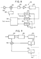
- la figure 9 est un bloc-diagramme de chacun des circuits de démodulation CDMA inclus l'unité de réception de la figure 8;
- la figure 10 est un bloc-diagramme détaillé d'une unité d'émission inclus dans le terminal de la figure 7;
- la figure 11 est un bloc-diagramme de chacun des circuits de modulation CDMA inclus l'unité d'émission de la figure 10;
- la figure 12 représente un motif de trame GSM;
- la figure 13A montre des trames modulées par des séquences respectives orthogonales entr'elles formées à partir de trames GSM;
- la figure 13B montre une supertrame formée par une pluralité de trames successives modulées par une même séquence parmi ; et
- la figure 14 montre un format de message à l'interface Abis d'un réseau de type GSM.
- Figure 1 shows, in schematic form, a telecommunications network with mobiles implementing the invention;
- Figure 2 is a block diagram of a base station forming part of the network of Figure 1;
- Figure 3 is a detailed block diagram of a switching unit according to the invention;
- FIGS. 4A and 4B together form a detailed block diagram of the transmission modulation circuits included in the base station;
- FIGS. 5 and 6 together form a detailed block diagram of the reception demodulation circuits included in the base station;
- Figure 7 is a general block diagram of a terminal for establishing communications across the network of Figure 1;
- Figure 8 is a detailed block diagram of a receiving unit included in the terminal of Figure 7;
- Figure 9 is a block diagram of each of the CDMA demodulation circuits including the receiving unit of Figure 8;
- Figure 10 is a detailed block diagram of a transmitting unit included in the terminal of Figure 7;
- Figure 11 is a block diagram of each of the CDMA modulation circuits including the transmission unit of Figure 10;
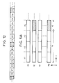
- Figure 12 shows a GSM frame pattern;
- FIG. 13A shows frames modulated by respective orthogonal sequences between them formed from GSM frames;
- FIG. 13B shows a superframe formed by a plurality of successive frames modulated by the same sequence from; and
- FIG. 14 shows a message format at the Abis interface of a GSM type network.
En référence à la figure 1, selon une réalisation, l'infrastructure d'un réseau de radiocommunications avec les mobiles pour la mise en oeuvre de l'invention, comprend, d'une part, un commutateur du service mobile, ou MSC, 1 raccordé à travers des liaisons MIC au Réseau Téléphonique Commuté RTC et des contrôleurs de stations de base 2a, 2b, supposés ici de type GSM, et, d'autre part, des stations de base 3, 4. Le Commutateur du Service Mobile est chargé de l'acheminement des communications en provenance de et vers les mobiles, dans une zone géographique donnée. Les contrôleurs de station de base 2a, 2b reliés à un Commutateur du Service mobile sont des commutateurs locaux des communications, assurant par ailleurs une fonction de pilotage d'une ou plusieurs stations de base 3, 4. Les stations de base 3, 4 assurent l'émission/réception radio des communications vers/en provenance des mobiles 6, 7. Une émission radio entre une station de base et un mobile peut être établie directement, dans le cas d'un réseau terrestre, ou via un satellite relais 5, dans le cas d'un réseau par satellite. De plus amples informations concernant les réseaux GSM sont fournies dans l'ouvrage "The GSM System for Mobile Communications" de Michel MOULY et Marie-Bernadette PAUTET, publié par les auteurs, Edition 1992 ainsi que dans les Recommandations ETSI relatives au GSM.With reference to FIG. 1, according to one embodiment, the infrastructure of a radiocommunication network with the mobiles for implementing the invention, comprises, on the one hand, a mobile service switch, or MSC, 1 connected via MIC links to the PSTN Switched Telephone Network and
L'invention propose d'utiliser des stations de base 3, 4 utilisant un mode de fonctionnement au moins partiellement CDMA, le reste de l'infrastructure, à savoir les contrôleurs de station de base 2a, 2b et les commutateurs du Service mobile 1, utilisant avantageusement les éléments des réseaux existants, tels que GSM.The invention proposes using
En référence à la figure 2, une station de base 3, 4 mettant en oeuvre l'invention comprend une unité d'aiguillage et de formation de message 38, une chaîne d'émission 36, une chaîne de réception 36' et une antenne 37. Une sortie de la chaîne d'émission 36 et une entrée de la chaîne de réception 36' sont couplées à l'antenne 37.With reference to FIG. 2, a
La chaîne d'émission 36 comprend M files d'attente d'émission 30-1 à 30-M dont des sorties respectives sont appliquées à des entrées de M unités de modulation par code 32-1 à 32-M. Les sorties respectives des M unités de modulation par code 32-1 à 32-M sont appliquées à une entrée d'une unité d'émission radio 34. La chaîne de réception 36' comprend une unité de réception radio 35 dont une sortie s'applique à M unités de démodulation par code 33-1 à 33-M, et M files d'attente de réception 31-1 à 31-M dont des entrées reçoivent les sorties respectives des M unités de démodulation par code 33-1 à 33-M.The
L'unité d'aiguillage et de formation de message 38 est couplée, d'une part, aux M entrées respectives des files d'attente 30-1 à 30-M à travers un premier bus B1 et, d'autre part, aux M sorties respectives des files d'attente 31-1 à 31-1 à travers un second bus B2. Cette unité 38 est fournie ici pour coupler, ou interfacer, un contrôleur de station de base de type G.S.M 2a, 2b aux chaînes d'émission et de réception 36 et 36' opérant au moins partiellement en CDMA; elle est donc localisée au niveau définie en G.S.M par l'interface Abis entre contrôleur de station de base G.S.M et station de base G.S.M.The routing and
Comme montré dans la figure 14, l'interface Abis définit un format de message particulier pour les messages transmis et reçus par un contrôleur de station de base 2a, 2b. Chaque message est relatif à un canal, ou sous-canal, particulier et possèdent plusieurs champs dont un champ identifiant le type de canal véhiculé "CH. TYPE", un champ identifiant le rang "TS-n°" de l'intervalle temporel dans la trame TDMA véhiculant ce canal, et éventuellement le rang "SC n°" d'un sous-canal à l'intérieur d'un canal, et enfin un champ de données utiles "DATA". Une information particulière d'identification d'un émetteur/récepteur "TRX" dans une station de base destinataire d'un message donné est portée par le niveau LIAISON, au sens des Recommandations OSI de l'ISO. La définition d'un TRX est donnée à la page 212 de l'ouvrage "The GSM System for Mobile Communications" de Michel MOULY et Marie-Bernadette PAUTET, publié par les auteurs, Edition 1992.As shown in Figure 14, the Abis interface defines a particular message format for the messages transmitted and received by a
Comme montré dans la figure 12, dans le G.S.M, la structure élémentaire de support de transmission radioélectrique des données est appelée "trame". Une telle trame est définie par 8 intervalles temporels multiplexés IT0-IT7, qui sont répétés avec la périodicité de la trame. Chaque intervalle temporel est destiné à véhiculer un canal ou plusieurs sous-canaux. Dans le G.S.M, quatre types de canal sont distingués, à savoir les canaux de trafic (TCH en littérature anglo-saxonne pour Traffic CHannel), les canaux dédiés (DCCH en littérature anglosaxonne pour Dedicated Control CHannel), les canaux de contrôle commun (CCCH en littérature anglo-saxonne pour Common Control CHannel) et les canaux de diffusion d'informations générales (BCCH en littérature anglo-saxonne pour Broadcast Control CHannel). Certains canaux, par exemple les canaux dédiés DCCH et les canaux de diffusion d'informations générales BCCH véhiculent chacun des sous-canaux, tels que les sous-canaux SACCH (Slow Associated Control CHannel) pour les canaux DCCH ou les sous-canaux SCH (Synchronisation Channel) pour les canaux BCCH. Les motifs d'apparition des données, sous la forme de bursts, dans des intervalles temporels, ou portions d'intervalles temporels, pour former un canal, ou un sous-canal, sont définies d'une manière très particulière dans le cadre du G.S.M, avec des structures de supertrame, hypertrame, etc...As shown in Figure 12, in the G.S.M, the elementary radio data transmission support structure is called "frame". Such a frame is defined by 8 multiplexed time intervals IT0-IT7, which are repeated with the periodicity of the frame. Each time interval is intended to convey a channel or several subchannels. In GSM, four types of channel are distinguished, namely the traffic channels (TCH in Anglo-Saxon literature for Traffic CHannel), dedicated channels (DCCH in Anglo-Saxon literature for Dedicated Control CHannel), the common control channels (CCCH in Anglo-Saxon literature for Common Control CHannel) and general information dissemination channels (BCCH in Anglo-Saxon literature for Broadcast Control CHannel). Certain channels, for example the dedicated DCCH channels and the general information broadcasting channels BCCH each carry subchannels, such as the SACCH (Slow Associated Control CHannel) subchannels for the DCCH channels or the SCH subchannels ( Channel Synchronization) for BCCH channels. The reasons for the appearance of data, in the form of bursts, in time intervals, or portions of time intervals, to form a channel, or a subchannel, are defined in a very specific way in the context of GSM. , with superframe, hyperframe structures, etc.
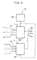
Comme montré dans la figure 3, l'unité 38, recevant des messages au format de la figure 13, comprend un circuit d'aiguillage 380, une table d'association 382 et un circuit de formation de message 381. Le bus de sortie B1 du circuit d'aiguillage 380 comprend M liaisons appliquées aux M entrées respectives des files d'attente 32-1 à 32-M. Les messages MES reçus en provenance du contrôleur de station de base sont appliqués à une entrée du circuit d'aiguillage 380. L'unité d'aiguillage 380 aiguille en conséquence le ou les paquet(s) de données utiles DATA contenu(s) dans un message MES vers celle des files d'attente 30-1 à 30-M qui est associée, dans la table d'association 382, aux informations :
- (a) - de rang "TS-n°" de l'intervalle temporel dans la trame véhiculant ce canal, ou éventuellement rang "SC n°" d'un sous-canal à l'intérieur d'un canal,
qui sont portées par le message MES, et éventuellement - (b) - d'identification de TRX,
qui est portée par le niveau LIAISON du protocole d'échange des messages MES.
- (a) - of rank "TS-n °" of the time interval in the frame carrying this channel, or possibly rank "SC n °" of a subchannel within a channel,
which are carried by the MES message, and possibly - (b) - identification of TRX,
which is carried by the LINK level of the MES message exchange protocol.
Dans le cas ou la station de base 3, 4 fonctionne en mode combiné CDMA/TDMA selon la réalisation décrite ci-après, la table d'association 382 peut associer aux informations précitées, outre le rang d'une file d'attente identifiant une unité de modulation par code donnée, un rang d'intervalle temporel dans une trame. Dans ce cas, l'unité d'aiguillage est synchronisée sur la fréquence d'apparition des trames et intervalles temporels dans la trame pour transmettre des paquets de données dans les files d'attente 30-1 à 30-M à des instants respectifs synchronisés avec les instants d'apparition des intervalles temporels dans une trame.In the case where the
En outre, avantageusement, pour des raisons qui seront développées ultérieurement, il peut être prévu que la table d'association associe à tout message dont le champ "CH. TYPE" identifie une information de canal BCCH ou CCCH, une file d'attente donnée, et cela indépendamment de l'information véhiculée dans le champ de rang d'intervalle temporel. Par ailleurs, cette même table peut associer à tout message dont le champ "CH. TYPE" identifie une information de canal TCH, et le champ "TS n°" identifie le 7ème intervalle temporel IT7, la 3ème file d'attente.In addition, advantageously, for reasons which will be developed later, it can be provided that the association table associates with any message whose "CH. TYPE" field identifies BCCH or CCCH channel information, a given queue , and this independently of the information conveyed in the time interval rank field. Furthermore, this same table can associate with any message whose "CH. TYPE" field identifies TCH channel information, and the "TS No." field identifies the 7th time interval IT7, the 3rd queue.
En pratique, comme cela va maintenant être décrit plus en détail, cette association entre des informations portées par les champs " "TS n°", "SC n°", "CH. TYPE" et "TRX" et les files d'attente 30-1 à 30-M dépend des ressources d'émission qui sont allouées par la chaîne d'émission 36. Ainsi à titre d'exemple, dans le cas ou cette chaîne fonctionne en mode CDMA selon lequel à chaque canal est associée une séquence PN différente, la capacité totale sera égale au débit en bande de base de chaque canal (qui est modulé par une séquence PN respective) multiplié par le nombre de séquences PN. Pour un autre exemple dans lequel la chaîne fonctionne en mode combiné CDMA/TDMA, selon lequel à chaque canal est associée une séquence parmi une pluralité de séquences orthogonales et un intervalle temporel de trame, la capacité totale sera égale au débit en bande de base d'un canal (occupant un intervalle temporel par trame) modulé par les séquences orthogonales, multiplié par le nombre de séquences et par le nombre d'intervalles temporels dans une trame. Une adéquation doit exister entre la capacité de débit total à transmettre et les ressources d'émission fournies par la chaîne d'émission, et l'unité 38 est chargée de l'aiguillage de chaque canal vers une ressource particulière en associant préalablement aux informations véhiculées dans les messages reçus MES, des informations d'identification de canaux d'émission.In practice, as will now be described in more detail, this association between information carried by the fields "" TS No. "," SC No. "," CH. TYPE "and" TRX "and the queues 30-1 to 30-M depend on the transmission resources which are allocated by the
Ainsi, de manière schématique, la fonction d'association définie par la table d'association 382 est donnée de la manière suivante:
(TS-n°, SC n°, TRX) ou ("CH tYPE", TS-n°, SC n°, TRX) → (PN) en mode d'émission CDMA, où PN désigne une séquence PN;
ou par :
(TS-n°, SC n°, TRX) ou (TS-n°, SC n°, TRX, "CH TYPE") → (Hm) en mode d'émission CDMA, où Hm désigne l'une d'une pluralité de séquences orthogonales entr'elles, pour une solution du type décrit dans le brevet US-A-5 103 459;
ou encore par :
(TS-n°, SC n°, TRX) ou (TS-n°, SC n°, TRX, "CH TYPE") → (Hm, ITj) en mode combiné TDMA/CDMA, ou Hm désigne l'une d'une pluralité de séquences orthogonales entr'elles, et ITj désigne un intervalle temporel donné, pour une solution du type décrit dans la réalisation préférée qui va suivre.Thus, schematically, the association function defined by the association table 382 is given as follows:
(TS-n °, SC n °, TRX) or ("CH tYPE", TS-n °, SC n °, TRX) → (PN) in CDMA transmission mode, where PN denotes a PN sequence;
or by :
(TS-n °, SC n °, TRX) or (TS-n °, SC n °, TRX, "CH TYPE") → (Hm) in CDMA transmission mode, where Hm denotes one of plurality of orthogonal sequences between them, for a solution of the type described in patent US-A-5 103 459;
or by:
(TS-n °, SC n °, TRX) or (TS-n °, SC n °, TRX, "CH TYPE") → (Hm, ITj) in combined TDMA / CDMA mode, or Hm denotes one of 'a plurality of orthogonal sequences between them, and ITj denotes a given time interval, for a solution of the type described in the preferred embodiment which follows.
Les données d'association mémorisées dans la table d'association 382 sont, en outre, utilisées pour l'allocation d'un canal à un mobile. Ainsi, un canal GSM alloué par l'infrastructure à un mobile sera traduit en un canal CDMA. Un messsage véhiculant une information d'identification de ce canal CDMA sera émis à destination du mobile lors de l'allocation de ce canal au mobile.The association data stored in the association table 382 are also used for allocating a channel to a mobile. Thus, a GSM channel allocated by the infrastructure to a mobile will be translated into a CDMA channel. A message conveying information identifying this CDMA channel will be sent to the mobile when this channel is allocated to the mobile.
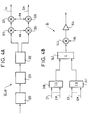
Comme montré dans la figure 4A, dans la réalisation décrite, chaque unité de modulation 32-m, m compris entre 1 et M, comprend en cascade un circuit de codage convolutionnel 320, un circuit d'entrelacement 321, un circuit de modulation de phase QPSK 322, et sur chacune de deux voies parallèles, deux multiplieurs identifiés par les repères 323 et 325 pour l'une des deux voies, et par les repères 324 et 326 pour l'autre des deux voies. Le circuit de codage 320 est un codeur convolutionnel, par exemple de type Viterbi de longueur de contrainte K=7 et de rapport r = 1/2. Il a pour fonction de mettre en oeuvre un codage qui offre une garantie de la qualité de la liaison. Un tel circuit de codage est bien connu de l'homme de l'art. Les paquets de données en bande de base issus de la file d'attente 30-m sont donc modulés par code par le circuit de modulation 32-m, puis entrelacées par le circuit 321. Le signal résultant entrelacé est modulé en phase QPSK (Quadrature Phase Shift keying) par le circuit 322. Ce dernier 322 produit deux composantes de signal en quadrature qui sont chacune appliquée aux deux multiplieurs 323, 325 et 324, 326 de la voie considérée.As shown in FIG. 4A, in the embodiment described, each modulation unit 32-m, m comprised between 1 and M, comprises in cascade a
Dans la réalisation décrite ici, le fonctionnement du réseau est tel que tous les signaux émis à l'intérieur d'une cellule (réseaux terrestres) ou d'un faisceau (réseaux par satellite) utilisent une même séquence PN (pseudo-noise) qui est différente d'une séquence PN utilisée par une cellule, ou faisceau, voisin(e). A l'intérieur d'une cellule, un signal à destination d'une station, tel que terminal, particulière est en outre codé par un séquence particulière qui est orthogonale aux séquences utilisées pour les signaux à destination d'autres stations dans la même cellule ou le même faisceau.In the embodiment described here, the operation of the network is such that all the signals transmitted inside a cell (terrestrial networks) or of a beam (satellite networks) use the same PN (pseudo-noise) sequence which is different from a PN sequence used by a neighboring cell, or beam. Inside a cell, a signal to a particular station, such as terminal, is further coded by a particular sequence which is orthogonal to the sequences used for signals to other stations in the same cell or the same beam.
Typiquement, les séquences PN consistent en des séquences pseudo-aléatoires identiques qui sont décalées temporellement entr'elles pour des cellules distinctes. Les séquences orthogonales sont par exemple des fonctions de Walsh, également connues sous les termes de "séquences de Hadamard".Typically, PN sequences consist of identical pseudo-random sequences which are time-shifted between them for separate cells. Orthogonal sequences are, for example, Walsh functions, also known as "Hadamard sequences".
Les séquences de Hadamard sont obtenues à partir d'une matrice de Hadamard de rang M, M étant une puissance de 2, telle que: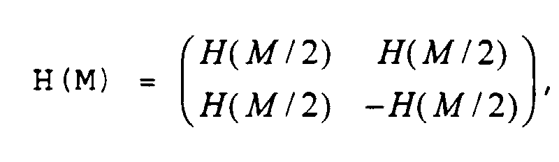

Une séquence de Hadamard Hm, m compris entre 1 et M, est l'une respective des lignes M de la matrice de Hadamard. Une matrice de Hadamard de rang M contient donc M séquences, chacune ayant une longueur de M bits. Les séquences de Hadamard d'ordre M possèdent la propriété que sur un intervalle de M symboles, la corrélation entre les différentes séquences est nulle, étant entendu que ces différentes séquences sont alignées temporellement. Cela résulte du fait que chaque séquence diffère de toute autre séquence pour la moitié des bits qui la composent.A Hadamard Hm sequence, m between 1 and M, is a respective one of the lines M of the Hadamard matrix. A Hadamard matrix of rank M therefore contains M sequences, each having a length of M bits. Hadamard sequences of order M have the property that over an interval of M symbols, the correlation between the different sequences is zero, it being understood that these different sequences are aligned in time. This results from the fact that each sequence differs from any other sequence for half of the bits which compose it.
En revenant à la figure 4A, pour l'unité de modulation 32-m, les deux composantes de signal modulé QPSK en quadrature sont toutes deux multipliées par une séquence de Hadamard Hm de rang m et par une séquence PN associée à la station de base 3, 4 considérée, pour produire deux signaux en quadrature modulés par code Im et Qm. Comme montré dans la figure 4B, dans l'unité d'émission radio 34, les différents signaux en quadrature Im et Qm, m compris entre 1 et M, issus des différentes unités de modulation par code 32-1 à 32-M sont additionnés au moyen d'additionneurs 340, 341 et 342. Le signal d'addition résultant est modulé par une porteuse d'émission PE avant d'être amplifié par un amplificateur 344 pour être émis à travers l'antenne 37.Returning to FIG. 4A, for the 32-m modulation unit, the two components of QPSK modulated signal in quadrature are both multiplied by a Hadamard Hm sequence of rank m and by a PN sequence associated with the
Ce signal, émis à travers l'antenne 37, est tel que représenté dans la figure 13. Il utilise par exemple un motif élémentaire de trame à quatre intervalles temporels it1-it4 qui se répètent à la fréquence de trame. Un signal de trame donné est associé à une séquence de Hadamard respective Hm, m étant par exemple compris entre 1 et 64, la matrice de Hadamard choisie étant de rang M=64. Un canal d'émission dans le réseau décrit ici et défini par un intervalle temporel itj, j compris entre 1 et 4, et une séquence de Hadamard Hm, correspond par son contenu, sauf cas particulier, à un canal TDMA dans le GSM. De manière très avantageuse, le trafic BCCH est véhiculé par les canaux associés à une séquence de Hadamard donnée, telle que H0. La table d'association 382 réalise donc cette correspondance. Dans la GSM, les canaux de trafic, dits full-rate, notés TCH/F qui sont reçus par l'unité d'aiguillage 38 sont tels qu'ils occupent un intervalle de même rang dans chaque trame GSM successive de 8 intervalles temporels. Pour ces canaux TCH/F, de manière avantageuse, en se référant au brevet américain US-A- 5 373 502 au nom de ALCATEL.N.V, la table d'association 382 associe à un intervalle temporel sur deux un canal défini par un intervalle temporel itj de la trame montrée dans la figure 13 et une séquence de Hadamard Hm et à l'autre de ces deux intervalles temporels, le même intervalle temporel itj de la trame mais une séquence de Hadamard Hm' distincte de Hm. Ainsi le canal TCH/F est reçu par une station distante par moitié codée sur deux séquences de Hadamard distinctes mais sur un même intervalle temporel.This signal, transmitted through the
Comme montré dans la figure 13B, la structure de trame élémentaire montrée à la figure 13A s'inscrit dans une structure de supertrame constituée de N trames élémentaires, (N-1) de ces trames véhiculant le contenu des canaux GSM, et une trame véhiculant des données de synchronisation PN. Il est rappelé que l'allocation d'un canal de type CDMA ou CDMA/TDMA combiné par la table d'association à un canal GSM peut être quelconque, sauf pour ce qui concerne les canaux de signalisation BCCH et CCCH qui devront de préférence être modulées par une même séquence de Hadamard. De même avantageusement, les canaux de trafic full-rate seront divisés, pour un intervalle temporel sur deux, sur une séquence de Hadamard et pour l'autre de ces intervalles temporels sur une autre séquence de Hadamard, en utilisant un même intervalle temporel d'émission.As shown in FIG. 13B, the elementary frame structure shown in FIG. 13A is part of a superframe structure made up of N elementary frames, (N-1) of these frames conveying the content of the GSM channels, and a frame conveying PN synchronization data. It is recalled that the allocation of a CDMA or CDMA / TDMA type channel combined by the association table to a GSM channel can be arbitrary, except for the BCCH and CCCH signaling channels which should preferably be modulated by the same Hadamard sequence. Likewise advantageously, the full-rate traffic channels will be divided, for a time interval out of two, on a Hadamard sequence and for the other of these time intervals over another sequence of Hadamard, using the same time interval d ' program.
Comme montré dans la figure 13B, pour chacune des séquences de Hadamard, les trames sont combinées en supertrames ST comprenant K trames élémentaires, K étant un nombre entier. Ces supertrames définissent des motifs périodiques de répartition des canaux. En outre, chaque supertrame ST comprend une séquence d'acquisition SS. La séquence d'acquisition SS est émise une fois pendant une durée donnée pour chaque supertrame produite. Elle est émise par chaque unité de modulation 32-1 à 32-M en subissant uniquement la modulation de code PN, et aucune modulation par séquence de Hadamard. En résultat, une station réceptrice distante recevra dans l'intervalle temporel coïncidant avec la séquence SS, cette séquence SS avec une puissance M fois supérieure à la puissance normalement reçue pour l'un des canaux d'émission défini dans notre réalisation par un intervalle temporel est une séquence de Hadamard.As shown in FIG. 13B, for each of the Hadamard sequences, the frames are combined into ST superframes comprising K elementary frames, K being an integer. These superframes define periodic patterns of channel distribution. In addition, each superframe ST comprises an acquisition sequence SS. The SS acquisition sequence is sent once during a given duration for each superframe produced. It is transmitted by each 32-1 to 32-M modulation unit undergoing only PN code modulation, and no modulation by Hadamard sequence. As a result, a remote receiving station will receive in the time interval coinciding with the sequence SS, this sequence SS with a power M times greater than the power normally received for one of the transmission channels defined in our embodiment by a time interval is a Hadamard sequence.
Les supertrames ainsi produites sont reçues par une station réceptrice 6, par exemple un terminal, montrée à la figure 7. Le terminal 6 comprend un duplexeur 61 qui est relié à une antenne, et dont une entrée est connectée à une sortie d'une unité d'émission 62, et dont une sortie est appliquée à une entrée d'une unité de réception 63. La station réceptrice comprend, en outre, une unité centrale 64.The superframes thus produced are received by a receiving
En référence à la figure 8, l'unité de réception 63 du terminal 6,7 comprend un amplificateur RF 630, un multiplieur 631, un générateur de porteuse 632, un filtre passe-bande 633, un amplificateur IF 634, un convertisseur analogique/numérique 635, 3 unités de démodulation de code 65a-65c et un circuit de démultiplexage-retard 636. Le signal d'addition modulé par une porteuse d'émission PE pour être émis à travers l'antenne 37 par la station 2a, 2b est reçu par l'antenne 60 du terminal 6. Ce signal d'addition modulé reçu est amplifié RF par l'amplificateur 630, puis démodulé par la porteuse de démodulation produite par le générateur 632, filtré passe-bande dans le filtre 633, amplifié IF dans l'amplificateur 634, puis converti en un signal d'addition numérique par le convertisseur 635.With reference to FIG. 8, the
Ce signal d'addition numérique est appliqué en parallèle à trois entrées respectives des trois unités de démodulation de code 65a-65c. Comme montré dans la figure 9, chaque unité de démodulation de code comprend un corrélateur PN/QPSK 651, un détecteur de phase 652, un décodeur de convolution 653, un générateur de séquence PN 655, un générateur de séquence d'Hadamard 656 et un multiplieur 654. Une première entrée du corrélateur 651 reçoit le signal d'addition numérique issu du convertisseur 635, et une seconde entrée dudit corrélateur 651 reçoit le signal résultant de la multiplication des séquences PN et de Hadamard respectivement produites par les générateurs 655 et 656. Le corrélateur produit deux signaux en quadrature appliqués à une entrée du détecteur de phase 652 dont une sortie est reliée à une entrée d'un décodeur de convolution 653 assurant un décodage par treillis du codage de Viterbi.This digital addition signal is applied in parallel to three respective inputs of the three
La séquence d'acquisition SS est reçue, codée par la séquence PN, avec une puissance égale à M fois la puissance d'un canal pris seul, tel que canal de traffic. Lors de l'initialisation du terminal, le générateur de séquence de Hadamard 656 dans le démodulateur de code 65a produit une séquence de Hadamard avec tous les bits à "1". Cela permet au corrélateur de s'affranchir de la modulation par séquence de Hadamard Hm pour acquérir la synchronisation PN. Cette synchronisation PN est obtenue au moyen du corrélateur 651, de manière connue.The acquisition sequence SS is received, coded by the sequence PN, with a power equal to M times the power of a channel taken alone, such as a traffic channel. When initializing the terminal, the
A l'issue de cette acquisition de synchronisation PN, le générateur de séquence de Hadamard 656 dans le démodulateur de code 65a est commandé pour produire une séquence de Hadamard prédéfinie. Cette séquence de Hadamard prédéfinie est la séquence, par exemple H0, modulant par code les canaux BCCH et CCCH. En résultat, elle produit, en sortie, par démodulation de code, les diverses informations, véhiculées par exemple dans les canaux communs PCH, SCH et FCH qui sont appliquées à une entrée de l'unité centrale 64. En fonction de ces informations, l'unité centrale 64 assure des fonctions de synchronisation temporelle (SCH), fréquentielle (FCH) pour la correction de la fréquence du générateur 632, et de détection d'appel entrant (PCH). Le contenu des messages portés par le canal PCH d'appel des mobiles est modifié de sorte à y inclure, outre l'adresse du mobile appelé, le canal, défini par la ou les séquence(s) de Hadamard et le ou les rang(s) d'intervalle temporel parmi les intervalles temporels it1 à it4 de trame, qui véhicule(nt) une communication à établir ainsi que la signalisation associée.At the end of this PN synchronization acquisition, the
L'unité centrale 64 pilote en conséquence, par des signaux de commande CO, les unités d'émission et de réception 62 et 63 pour synchroniser les réception et émission de la communication sur le(s) rang(s) d'intervalle temporel et la ou les séquences de Hadamard identifié par le canal PCH. L'une des deux ou les deux unités de démodulation par code 65b et 65c ont alors pour fonction de démoduler par code la communication reçue. Les deux unités sont utilisées lorsqu'est mise en oeuvre la solution décrite dans le brevet précité US-A- 5 373 502. Dans ce cas, les signaux produits aux sorties respectives des deux unités 65b et 65c seront combinés dans un circuit 636 pour produire un unique signal Sout reconstituant le signal original en bande de base transmis.The
En référence aux figures 10 et 11, l'unité d'émission du terminal 6, 7 comprend un circuit d'aiguillage 620, deux files d'attente 621a et 621b, deux unités de modulation 66a et 66b, un additionneur 622, un multiplieur 623, et un amplificateur RF 624. L'utilisation de deux files d'attente 621a et 621b et unités de modulation associées 66a et 66b résulte de la mise en oeuvre de la solution décrite dans le brevet US-A- 5 373 502. L'unité d'aiguillage 620 aiguille la signalisation SIG et le signal en bande de base de communication Sin vers la file d'attente appropriée en fonction du canal destiné à véhiculer ces informations. Ces informations sont codées 660, entrelacées 661, modulées en phase QPSK 662, puis modulées en séquences PN 663-665 et Hadamard 666-668. Les séquences Hadamard produites dans les deux unités de modulation 66a et 66b sont distinctes entr'elles. Les signaux modulés par code issus des deux unités de modulation 66a et 66b sont sommés par l'additionneur 622, et le signal d'addition résultant est modulé par une porteuse d'émission avant d'être amplifié par l'amplificateur 624 pour émission à travers le duplexeur et l'antenne du terminal 6, 7.With reference to FIGS. 10 and 11, the transmission unit of the
En revenant à la figure 2 et en référence aux figures 3, 5 et 6, il est maintenant décrit le fonctionnement en réception par la station de base, des signaux émis par les différents mobiles 6, 7 d'une cellule, ou faisceau. Il est préalablement souligné que les mobiles sont synchronisés en émission selon la procédure de réglage de l'instant d'émission, dite du "timing advance" en G.S.M. Pour cela, avant établissement d'une communication, un mobile déclenche une émission sur le canal RACH relativement à la synchronisation qu'il a reçue de la station de base. Cette émission permet à la station de base de mesurer le double du temps de propagation mobile-station de base. En réponse, la station de base alloue au mobile un canal SACCH dans lequel est véhiculée une information d'avance temporelle que le mobile doit donner à son horloge par rapport à ce qu'il croit être l'horloge de la station de base, de sorte que les données ultérieurement émises par le mobile coïncident avec un intervalle temporel donné de la trame. L'information d'avance temporelle devra dans notre réalisation posséder une précision bien supérieur à celle du G.S.M, pour tenir compte de la modulation CDMA. Un nombre de bits supérieur à ceux définis à cette fin dans le GSM sera donc utilisé dans le SACCH.Returning to FIG. 2 and with reference to FIGS. 3, 5 and 6, there is now described the operation in reception by the base station, of the signals transmitted by the
La station de base reçoit donc les différents canaux sur des intervalles temporels parfaitement synchronisés, et modulées par des séquences de Hadamard, tel que cela est montré dans la figure 14.The base station therefore receives the different channels over perfectly synchronized time intervals, modulated by Hadamard sequences, as shown in FIG. 14.
Comme montré dans la figure 6, ces différents signaux sont successivement amplifiés RF par un amplificateur 350, démodulés par une porteuse de démodulation produite par un générateur 352, filtrés par un filtre passe-bande 353, amplifiés BF 354, et subissent finalement une conversion analogique/numérique 355. Le signal composite issu du convertisseur analogique/numérique 355 est appliqué aux entrées respectives des unités de démodulation par code 33-1 à 33-M. Chaque unité de démodulation par code 33-m, m compris entre 1 et M, comprend en cascade un corrélateur QPSK/PN 330, une transformée de Hadamard rapide Hm et un décodeur de convolution 332. La transformée de Hadamard rapide opère pour la séquence Hm. En sortie d'un décodeur de convolution 332 de l'une des unités de démodulation par code 33-m, est produit le signal en bande de base correspondant aux trames "portées" par l'une respective des séquences de Hadamard Hm, m compris entre 1 et M=64 dans la figure 13A.As shown in Figure 6, these different signals are successively RF amplified by an
Dans l'unité d'aiguillage et de formation de message 38, le circuit de formation de message 381, reçoit dans le bus B2, à travers les files d'attente respectives 31-1 à 31-M, ces différents signaux en bande de base. Le circuit 38 est synchronisé sur la période d'intervalle temporel et de trame, et associe à chaque paquet de canal issu de chaque démodulateur par code, des données d'identification et de rang de canal TDMA, d'identification d'émetteur/récepteur TRX selon le format GSM.In the routing and
Ainsi, à titre d'exemple, tout intervalle temporel itj de rang j=2 reçu en provenance de la mème = 6ème file d'attente se verra associer un champ "CH. TYPE" identifiant une information de canal TCH, et un champ de rang "TS n°" identifiant le 7ème intervalle temporel IT7. Le circuit de formation de message forme alors un message incluant le paquet de données véhiculé dans l'intervalle temporel considéré et les informations d'identification et de rang de canal TDMA. Ces messages sont alors transmis à destination du contrôleur de station de base 2a, 2b.Thus, by way of example, any time interval itj of rank j = 2 received from the m th = 6 th queue will be associated with a "CH. TYPE" field identifying channel information TCH, and a rank field "TS n °" identifying the 7th IT7 time interval. The message forming circuit then forms a message including the data packet carried in the time interval considered and the identification information and TDMA channel rank. These messages are then transmitted to the
De manière générale, en réception, la fonction d'association opère selon un processus d'association inverse au processus d'association en émission. Ainsi, en réception, la fonction d'association définie par la table d'association 382 est donnée par:
(PN) → (CH. TYPE, TS-n°, SC n°, TRX) en mode réception CDMA, où PN désigne une séquence PN particulière, pour une solution du type décrite dans le brevet US-A-4 901 307;
ou par :
(Hm) → (CH. TYPE, TS-n°, SC n°, TRX) en mode réception CDMA, où Hm désigne l'une d'une pluralité de séquences orthogonales entr'elles, pour une solution du type décrit dans le brevet US-A-5 103 459;
ou encore par :
(Hm, ITj) → (CH. TYPE, TS-n°, SC n°, TRX) en mode combiné TDMA/CDMA, ou Hm désigne l'une d'une pluralité de séquences orthogonales entr'elles, et ITj désigne un intervalle temporel donné, pour une solution du type décrit dans la réalisation préférée qui précède.Generally, on reception, the association function operates according to a process of association opposite to the association process on transmission. Thus, on reception, the association function defined by the association table 382 is given by:
(PN) → (CH. TYPE, TS-n °, SC n °, TRX) in CDMA reception mode, where PN denotes a particular PN sequence, for a solution of the type described in patent US-A-4,901,307;
or by :
(Hm) → (CH. TYPE, TS-n °, SC n °, TRX) in CDMA reception mode, where Hm denotes one of a plurality of orthogonal sequences between them, for a solution of the type described in the US-A-5,103,459;
or by:
(Hm, ITj) → (CH. TYPE, TS-n °, SC n °, TRX) in combined TDMA / CDMA mode, or Hm denotes one of a plurality orthogonal sequences between them, and ITj denotes a given time interval, for a solution of the type described in the above preferred embodiment.
Claims (9)
caractérisée en ce que chaque message véhicule, en outre, des données d'identification de rang de canal TDMA (TS N°, SC N°) de canal véhiculé, et
en ce que ladite unité comprend:
characterized in that each message further carries TDMA channel rank identification data (TS No., SC No.) of the channel conveyed, and
in that said unit comprises:
Applications Claiming Priority (2)
| Application Number | Priority Date | Filing Date | Title |
|---|---|---|---|
| FR9607619 | 1996-06-19 | ||
| FR9607619A FR2750281B1 (en) | 1996-06-19 | 1996-06-19 | INTERFACE UNIT FOR MOBILE RADIO COMMUNICATIONS NETWORK |
Publications (1)
| Publication Number | Publication Date |
|---|---|
| EP0814577A1 true EP0814577A1 (en) | 1997-12-29 |
Family
ID=9493204
Family Applications (1)
| Application Number | Title | Priority Date | Filing Date |
|---|---|---|---|
| EP97401358A Withdrawn EP0814577A1 (en) | 1996-06-19 | 1997-06-16 | Interface unit for a mobile radio communication network |
Country Status (4)
| Country | Link |
|---|---|
| EP (1) | EP0814577A1 (en) |
| JP (1) | JPH1098456A (en) |
| AU (1) | AU726766B2 (en) |
| FR (1) | FR2750281B1 (en) |
Cited By (2)
| Publication number | Priority date | Publication date | Assignee | Title |
|---|---|---|---|---|
| EP0954111A1 (en) * | 1998-04-27 | 1999-11-03 | Siemens Aktiengesellschaft | Radio communications apparatus and method of communicating control data for use in a radio communications apparatus |
| FR2785118A1 (en) * | 1998-10-26 | 2000-04-28 | Cit Alcatel | CHANNEL ACQUISITION AND TRACKING MODULE FOR A RADIO COMMUNICATION SYSTEM |
Citations (6)
| Publication number | Priority date | Publication date | Assignee | Title |
|---|---|---|---|---|
| US4799252A (en) * | 1985-07-31 | 1989-01-17 | U.S. Philips Corp. | Digital radio transmission system |
| US5260967A (en) * | 1992-01-13 | 1993-11-09 | Interdigital Technology Corporation | CDMA/TDMA spread-spectrum communications system and method |
| EP0600713A2 (en) * | 1992-12-01 | 1994-06-08 | Nokia Mobile Phones Ltd. | Communication method and system |
| US5369664A (en) * | 1991-08-12 | 1994-11-29 | Matsushita Electric Industrial Co., Ltd. | Mobile communication system |
| EP0658991A1 (en) * | 1993-12-08 | 1995-06-21 | Nec Corporation | Mobile communication system capable of transmitting and receiving a radio signal obtained by TDMA and CDMA without interference |
| WO1995023464A1 (en) * | 1994-02-25 | 1995-08-31 | Motorola Inc. | Method and apparatus for time division multiplexing the use of spreading codes in a communication system |
-
1996
- 1996-06-19 FR FR9607619A patent/FR2750281B1/en not_active Expired - Fee Related
-
1997
- 1997-06-16 EP EP97401358A patent/EP0814577A1/en not_active Withdrawn
- 1997-06-17 AU AU27548/97A patent/AU726766B2/en not_active Ceased
- 1997-06-19 JP JP16315297A patent/JPH1098456A/en active Pending
Patent Citations (6)
| Publication number | Priority date | Publication date | Assignee | Title |
|---|---|---|---|---|
| US4799252A (en) * | 1985-07-31 | 1989-01-17 | U.S. Philips Corp. | Digital radio transmission system |
| US5369664A (en) * | 1991-08-12 | 1994-11-29 | Matsushita Electric Industrial Co., Ltd. | Mobile communication system |
| US5260967A (en) * | 1992-01-13 | 1993-11-09 | Interdigital Technology Corporation | CDMA/TDMA spread-spectrum communications system and method |
| EP0600713A2 (en) * | 1992-12-01 | 1994-06-08 | Nokia Mobile Phones Ltd. | Communication method and system |
| EP0658991A1 (en) * | 1993-12-08 | 1995-06-21 | Nec Corporation | Mobile communication system capable of transmitting and receiving a radio signal obtained by TDMA and CDMA without interference |
| WO1995023464A1 (en) * | 1994-02-25 | 1995-08-31 | Motorola Inc. | Method and apparatus for time division multiplexing the use of spreading codes in a communication system |
Cited By (6)
| Publication number | Priority date | Publication date | Assignee | Title |
|---|---|---|---|---|
| EP0954111A1 (en) * | 1998-04-27 | 1999-11-03 | Siemens Aktiengesellschaft | Radio communications apparatus and method of communicating control data for use in a radio communications apparatus |
| WO1999056402A1 (en) * | 1998-04-27 | 1999-11-04 | Siemens Aktiengesellschaft | Radio communications apparatus and method of communicating control data for use in a radio communications apparatus |
| FR2785118A1 (en) * | 1998-10-26 | 2000-04-28 | Cit Alcatel | CHANNEL ACQUISITION AND TRACKING MODULE FOR A RADIO COMMUNICATION SYSTEM |
| EP0998065A1 (en) * | 1998-10-26 | 2000-05-03 | Alcatel | Channel module for acquisition and tracking used in a radio communication system |
| WO2000025450A1 (en) * | 1998-10-26 | 2000-05-04 | Alcatel | Module channel for acquiring and tracking in a radio communication system |
| US6813307B1 (en) | 1998-10-26 | 2004-11-02 | Alcatel | Module channel for acquiring and tracking in a radio communication system |
Also Published As
| Publication number | Publication date |
|---|---|
| JPH1098456A (en) | 1998-04-14 |
| AU2754897A (en) | 1998-01-08 |
| FR2750281B1 (en) | 1998-07-31 |
| AU726766B2 (en) | 2000-11-23 |
| FR2750281A1 (en) | 1997-12-26 |
Similar Documents
| Publication | Publication Date | Title |
|---|---|---|
| EP0095959B1 (en) | Frequency hopping radiocommunication system | |
| US5956332A (en) | High-speed data transmission in mobile communication networks | |
| FR2701178A1 (en) | Spread spectrum communication system with multiple users. | |
| WO2007104741A1 (en) | Method for optimizing allocation of resources in a cellular network using a shared radio transmission link, network and network adaptors thereof | |
| FR2577090A1 (en) | RADIOCOMMUNICATION SYSTEM | |
| EP0918404A1 (en) | Base station for mobile cellular radiocommunication system and synchronisation system for these base stations | |
| EP1070401A1 (en) | Cellular radio signal with additional channel assigned to downlink, corresponding method, system and base station | |
| EP0641096B1 (en) | Method with multiple access by orthogenal frequencies, corresponding central station, remote station, system and their use | |
| EP1759471B1 (en) | Terrestrial repeater with pseudo-random code redistribution on different carrier frequencies | |
| EP0817397B1 (en) | Method for switching a channel from a first to a second propagation path | |
| EP1198906B1 (en) | Radiocommunication method between a base station and mobile terminals, base stations and mobile terminals for implementing same | |
| FR2685588A1 (en) | RADIO TRANSMISSION SYSTEM COMPRISING AT LEAST ONE CENTER STATION AND A PLURALITY OF SATELLITE STATIONS. | |
| EP0814577A1 (en) | Interface unit for a mobile radio communication network | |
| EP0887950A1 (en) | Base station with antennas diversity for the transmission of unidirectional channels and corresponding method | |
| WO2009090317A1 (en) | Wideband radiocommunications system, complementary receiving station, and method of optimizing a data link in a radiocommunications system. | |
| CA2364829C (en) | Radio resources allocation process, base station for implementation and system incorporating the process | |
| CA2374339C (en) | Radio communication method between a base station and mobile terminals | |
| FR2719428A1 (en) | Transmission system formed from at least one base station, a satellite station and a node station and base station and satellite station suitable for such a system. | |
| FR2724085A1 (en) | TELECOMMUNICATIONS METHOD AND DEVICE PROVIDING ADAPTIVE TEMPORAL POSITIONING OF SALVES TRANSMISSION | |
| FR3091454A1 (en) | Communication system between improved base stations of a mobile radiocommunication system using a broadcast / multicast type of broadcasting mode to establish data transport links | |
| NL1005522C2 (en) | Method and communication system for CDMA data transfer. | |
| EP0702498A1 (en) | Multi-layered cellular radio communication network with beaconless cell | |
| FR2823042A1 (en) | PACKET SYNCHRONIZED BIDIRECTIONAL TRANSMISSION METHOD | |
| WO2010034947A1 (en) | Method for accessing a transmission without a frequency duplexer | |
| Bossom | of Deliverable: European ITS Framework Architecture |
Legal Events
| Date | Code | Title | Description |
|---|---|---|---|
| PUAI | Public reference made under article 153(3) epc to a published international application that has entered the european phase |
Free format text: ORIGINAL CODE: 0009012 |
|
| AK | Designated contracting states |
Kind code of ref document: A1 Designated state(s): DE ES FI FR GB IT SE |
|
| 17P | Request for examination filed |
Effective date: 19980629 |
|
| AKX | Designation fees paid |
Free format text: DE ES FI FR GB IT SE |
|
| RBV | Designated contracting states (corrected) |
Designated state(s): DE ES FI FR GB IT SE |
|
| RAP1 | Party data changed (applicant data changed or rights of an application transferred) |
Owner name: ALCATEL SPACE INDUSTRIES |
|
| STAA | Information on the status of an ep patent application or granted ep patent |
Free format text: STATUS: THE APPLICATION IS DEEMED TO BE WITHDRAWN |
|
| 18D | Application deemed to be withdrawn |
Effective date: 20050104 |