EP0814371B1 - Method and apparatus for feeding film cartridges in a photographic printer - Google Patents
Method and apparatus for feeding film cartridges in a photographic printer Download PDFInfo
- Publication number
- EP0814371B1 EP0814371B1 EP97109789A EP97109789A EP0814371B1 EP 0814371 B1 EP0814371 B1 EP 0814371B1 EP 97109789 A EP97109789 A EP 97109789A EP 97109789 A EP97109789 A EP 97109789A EP 0814371 B1 EP0814371 B1 EP 0814371B1
- Authority
- EP
- European Patent Office
- Prior art keywords
- cartridge
- cartridges
- film
- processor
- Prior art date
- Legal status (The legal status is an assumption and is not a legal conclusion. Google has not performed a legal analysis and makes no representation as to the accuracy of the status listed.)
- Expired - Lifetime
Links
Images


Classifications
-
- G—PHYSICS
- G03—PHOTOGRAPHY; CINEMATOGRAPHY; ANALOGOUS TECHNIQUES USING WAVES OTHER THAN OPTICAL WAVES; ELECTROGRAPHY; HOLOGRAPHY
- G03D—APPARATUS FOR PROCESSING EXPOSED PHOTOGRAPHIC MATERIALS; ACCESSORIES THEREFOR
- G03D15/00—Apparatus for treating processed material
- G03D15/001—Counting; Classifying; Marking
- G03D15/005—Order systems, e.g. printsorter
-
- G—PHYSICS
- G03—PHOTOGRAPHY; CINEMATOGRAPHY; ANALOGOUS TECHNIQUES USING WAVES OTHER THAN OPTICAL WAVES; ELECTROGRAPHY; HOLOGRAPHY
- G03B—APPARATUS OR ARRANGEMENTS FOR TAKING PHOTOGRAPHS OR FOR PROJECTING OR VIEWING THEM; APPARATUS OR ARRANGEMENTS EMPLOYING ANALOGOUS TECHNIQUES USING WAVES OTHER THAN OPTICAL WAVES; ACCESSORIES THEREFOR
- G03B27/00—Photographic printing apparatus
- G03B27/32—Projection printing apparatus, e.g. enlarger, copying camera
- G03B27/52—Details
- G03B27/62—Holders for the original
- G03B27/6271—Holders for the original in enlargers
- G03B27/6285—Handling strips
Definitions
- This invention relates to a method and apparatus for feeding a new type of cartridges that makes it possible to collate the film in each cartridge with the corresponding photoprints at the print finishing station after the film in each cartridge has been processed in a photoprinter.
- a conventional 135 film which is housed in a patrone, is cut to a plurality of strips each having six or so frames, put in a negative sheet and discharged for each customer at a position near the printing unit.
- a sorter is used to feed prints to the position where an operator for finishing the prints is stationed. If it is necessary to finish the prints and collate the prints with corresponding cartridges, the operator has to carry negative sheets discharged at the printing unit to the position where prints are discharged.
- Unexamined Japanese patent publication 7-36120 discloses a photoprinting processor for processing films stored in new type cartridges.
- This processor includes a rotary table mounted on a base.
- a plurality of cartridge holders are provided on the rotary table.
- a scanner unit and a print/exposure unit are provided across the rotary table from each other along a first line connecting two diametrically opposite cartridge holders when these two cartridges are at predetermined positions.
- a cartridge feed station is provided on the base along a second line perpendicular to the first line.
- the spool of the cartridge held by each holder is turned to feed film end into a film guide.
- the film end is caught between a driving and a pressure roller provided in the film feed path, the film is fed by the rollers.
- an end mark impressed on the film is detected.
- the film is wound back into the cartridge.
- Films stored in new type cartridges can be fed into processors by setting cartridges one by one in the respective cartridge holders on the rotary table. But since new type cartridges have been developed so that they can be automatically fed into processors, it is desirable to feed them automatically from the cartridge storage space with a carrier means.
- An object of this invention is to provide a method and apparatus for feeding film cartridges in which film cartridges are transported to a print collecting station after they have been fed into and out of the photoprinter so that film cartridges can be collated with prints with high efficiency.
- US 5 473 402 A discloses a method of feeding film cartridges to a printer for printing the films, wherein the films are separated from the cartridges, spliced to a long roll for printing, cut from the roll of spliced films into single films which are then rewound back into their cartridges after processing for collating the cartridges with their corresponding prints.
- the film orders are sorted beforehand, but only with respect to the different film, cassette and order types.
- US 5 231 439 A discloses a method of printing a single film in a cartridge by extracting the film in a printing station and retracting the film back into its own cartridge after printing and conveying the cartridge to a collating station to collate it with its associated prints. No sorting of the cartridges is mentioned.
- a plurality of film cartridges stored in a storage space are supplied one by one into the photoprinting processor to print films therein.
- the cartridges supplied into the processor contain developed films.
- the cartridge is moved back to its original position and then fed to the print collecting station, where it is collated with photoprints discharged from the photoprocessor to determine if their contents are identical.
- the film cartridges are sorted into cartridges containing developed films and those containing undeveloped films by detecting whether or not each cartridge has a nail, and only the former cartridges are supplied into the photoprinting processor. All the cartridges containing undeveloped films are ejected from the feed path leading to the print collecting station. If a signal indicating clogging of print paper or a print stop signal is produced while a cartridge containing a developed film is being fed into or out of the photoprinting processor, such a cartridge is also ejected from the feed path leading to the print collecting station. The remaining film cartridges are fed to the print collecting station.
- This apparatus distinguishes cartridges containing developed films from those containing undeveloped films, and supplies only the former into the photoprinting processor to print films therein. During printing or while a film cartridge containing a developed film is being fed into the photoprinting processor, it may become necessary to stop printing operations due to clogging of print paper or any other machine glitch.
- Fig. 1 is a plan view of an entire photoprocessor with a carrier means according to the present invention.
- the photoprocesser comprises a photo-developing unit 1, a photo-finisher 2 and a photoprinter 3.
- the photoprinter 3 is a rotary table type as disclosed in the aforementioned patent publication and is used exclusively to print films in new type film cartridges.
- a cartridge feeder/collector 4 feeds film cartridges X into the photoprinter 3 for printing, collects them out of the printer 3 after printing, and sends them onto a carrier means 5 through a discharge opening.
- a cartridge sorter 6 is provided on the carrier 5 to sort cartridges X containing undeveloped film.
- the carrier 5 extends to a point just short of a print collector 7 of the photo-finisher 2.
- the photoprinter 3 has a base 31 on which is rotatably supported a rotary table 32.
- the rotary table is rotated by a drive unit 33 comprising a rotary shaft supported by a support frame, and a motor for rotating the rotary shaft through a belt.
- Four cartridge holders 34 are mounted on the rotary table 32 at 90 ° intervals.
- a scanning station 35 and a print/exposure station 36 are provided around the rotary table 32, diametrically opposite to each other with respect to the center of the rotary table.
- the scanning station 35 Provided in the scanning station 35 are a pair of scanner units (not shown) located over and under a centerline that passes a point P1 on the feed path of film fed out of a cartridge set in one cartridge holder when it aligns with the scanning station. Film is wound into a film winder 36a.
- the print/exposure station 36 is basically identical in structure to the scanning station, having a pair of print/exposure units (not shown) provided over and under a point P2. Detail of the photoprinter 3 is omitted because it is disclosed in the aforementioned publication.
- the carrier means 5 includes an endless belt conveyor 52 provided between side frames 51 and driven between a front and a rear roller (not shown) by a motor 55 through a gear 54 and an intermediate roller 53.
- Numeral 56 indicates a cover case. The feed end 57 of the carrier means 5 is funnelled so that cartridges X can be fed smoothly into the carrier.
- the carrier means 5 At its delivery end, the carrier means 5 has a slightly inclined stock path 5' as shown in Fig. 9. The end of the stock path 5' is located adjacent the print collector 7.
- the sorter 6, provided at an intermediate portion of the carrier means 5, comprises a sorting lever 61 and a solenoid 62 for pivoting the lever 61.
- cartridge feed path is blocked by the lever 61 as shown in Fig. 3B, cartridges X are diverted from the feed path into an apron stage 63.
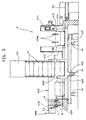
- the cartridge feeder/collector 4 is shown schematically in Fig. 2 and in detail in Figs. 4-8. Numerals (1)-(3) in these figures indicate different positions of cartridges being fed.
- the feeder/collector 4 comprises a cartridge storage/feed unit A and a longitudinal feed unit B.
- the cartridge storage/feed unit A comprises a cartridge stocker 401 for dropping cartridges one at a time, and a cartridge receiver 402 laterally movable in a lateral feed unit 403 for receiving cartridges dropped from the stocker 401.
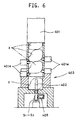
- the stocker 401 comprises, as shown in Fig. 6, a cartridge stocking cylinder in which a plurality of cartridges are stored one atop another, and two opposed pairs of solenoids 401a provided at the bottom end of the cylinder.
- a cartridge stocking cylinder in which a plurality of cartridges are stored one atop another, and two opposed pairs of solenoids 401a provided at the bottom end of the cylinder.
- the cartridge receiver 402 is a U-shaped member movable laterally in a gap 404 defined in the lateral feed unit 403.
- An endless belt 406 is connected to a protrusion 405 provided at the bottom end of the cartridge receiver 402. By turning one of two pulleys supporting the belt 406 in either direction with a motor 407, the cartridge receiver 402 is moved laterally.
- the letters S1, S2 and S3 indicate position detection sensors for detecting that the cartridge receiver 402 is in respective positions.
- the lateral feed unit 403 has a base at substantially the same height as the cartridge receiving surface of the cartridge receiver 402. Its end wall 403w (Fig. 4) has an IPI detection sensor 408 for determining whether the film in each cartridge X is developed or undeveloped by detecting whether or not the cartridge X has a nail d (to be described hereinbelow) (hereinafter "IPI detection").
- IPI detection for determining whether the film in each cartridge X is developed or undeveloped by detecting whether or not the cartridge X has a nail d (to be described hereinbelow)
- the detection sensor 408 determines that a cartridge has a nail if a lever t of a limit switch Ls (Fig. 5) is bent by being brought into contact with a pin p, and otherwise determines that there is no nail.
- the pin p and a spring k are received in a recess 409, while the limit switch LS is mounted on a support plate 403w of the end wall.
- the longitudinal feed unit B comprises feed guide 410, a carriage 420 movable along the guide 410, and a drive unit 440 for driving the carriage 420.
- the feed guide 410 comprises two parallel side walls 411 and guide rods 412 provided between the side walls 411 and extending into between the drive unit 440 and the rotary table 32 of the photoprinter 3.
- the carriage 420 comprises a base 421, support plates 422 provided on the four corners of the base 421 and partially protruding outwardly, and four support arms 422a slidably engaging the guide rods 412.
- the base 421 carries a solenoid 423 and a cartridge holder 424 having fork levers 424a at its front end.
- the cartridge holder 424 is pivotable about a pin 425 supported on the support plates 422, and coupled to an attitude control plates 426 on both sides by a pin 427 engaged in elongated holes 428.
- the attitude control plates 426 are formed with chevron-shaped second elongated holes 430 in which is inserted a support pin 429 fixed to the support plates 422. The plates 426 are thus movable.
- attitude control plates 426 are coupled together by a rod 431.
- a spring 432 provided between the support pin 429 and the rod 431 resiliently couples the holder 424 to the solenoid 423.
- the solenoid 423 has its solenoid rod 423a fixed to the rod 431 and thus coupled to the holder 424.
- a U-shaped coupling member 433 is provided between two support arms 422a on one side so as to be slidable along the guide rod 412.
- Springs 434 are mounted around the rod 412 between the coupling member 433 and the support arms 422a, restricting the sliding movement of the member 433 along the rod 412.
- a belt 441 of a drive unit 440 is fastened by a fastening means 435.
- Numeral 433a is a detection plate for a position detection sensor provided at one end of the coupling member 433. As shown in Fig. 4, position detection sensors S4 and S5 are provided near both ends of the longitudinal feed path.
- the drive unit 440 comprises, as seen in Figs. 4 and 7, an endless belt 441 and a motor 442 for driving the belt.
- the endless belt 441 is supported by a motor-driven pulley 443 and a pulley 443 provided near the end of the longitudinal feed path.
- Numeral 444 is a stopper.
- the longitudinal feed path is formed on a base plate 4x and includes a guide path 4a for smoothly feeding cartridges X from the lateral feed unit 403 onto the longitudinal feed path.
- Numeral 37 is a cartridge engaging means provided on the rotary table.
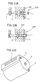
- Cartridges X used are new type ones as shown in Fig. 13.
- a new type cartridge is small but can entirely house a roll of film therein.
- the letter a is a spool shaft
- the letter b is a rotary shaft for opening and closing the door C
- the letter d is a nail. Depending on whether or not there is the nail, it is determined whether the film in the cartridge has been developed or not.
- the nail pushes the pin of the nail detection sensor 408 against the force of the spring k.
- the sensor thus detects that the film in the cartridge has not yet been developed. If the cartridge has no nail as shown in Fig. 13B, the pin p fits in the recess of the cartridge. The sensor thus detects that the film has been developed.
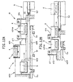
- Fig. 10 shows cartridges X being fed laterally.
- one cartridge X is dropped from the cartridge stocker 401, received in the cartridge receiver 402 and fed laterally, i.e. leftwardly so that the nail detection sensor 408 provided on the end wall can detect whether or not the cartridge has the nail.
- the cartridge is fed longitudinally in two different ways depending on whether the cartridge has the nail or not. We will explain how different in the later part of the description.
- the cartridge receiver 402 In the state of Fig. 10B, the cartridge receiver 402 is at a stop near the end wall.
- the pin p of the nail detection sensor 408 detects whether or not the cartridge has the nail. In the case shown, the cartridge has no nail, which means that the film in the cartridge has been developed. From this state, the cartridge is moved back in the direction of arrow past the feed position shown in Fig. 10A until the cartridge receiver 402 enters the longitudinal feed path.
- the cartridge X is caught by fork levers 424a of the cartridge holder 424 of the carriage 420 in the longitudinal feed path, and fed longitudinally.
- the cartridge X can move either leftwardly or rightwardly of either side wall 411 through either of openings 413, 414 formed in the side walls 411.
- the solenoid 423 is activated to pull the holder 424 until the cartridge X is held between the fork levers 424a and the apron 421a of the carriage 420.
- the cartridge X can now be fed longitudinally.
- the motor 442 of the drive unit 440 is started to move the endless belt 441 and advance the carriage 420 (in the direction of the arrow (a)).
- the cartridge X is engaged by the cartridge engaging means 37 on the rotary table 32.
- the solenoid 423 is activated to protrude the rod 423a, raise the fork levers 424a and open the cartridge X (as shown by the two-dot lines). If the cartridge has the nail, the carriage 420 moves back with the fork levers 424a kept shut. That is, the cartridge is returned to the original position in the longitudinal feed path while being held by the carriage 420.
- the cartridge X When the cartridge X is opened by raising the fork levers 424a, it is fed into the scanner and then print/exposure stations while being held by the cartridge engaging means 37, as the rotary table 32 is turned. After photoprinting/exposure, the cartridge returns to the position shown in Fig. 11B.
- the cartridge receiver 402 By the time the cartridge X returns to the original position, the next cartridge is received in the cartridge receiver 402 as shown in Fig. 12A. From this state, the cartridge receiver 402 approaches the cartridge X that has returned to the original position, and pushes it rightwardly as shown in Fig. 12B.
- this cartridge X When this cartridge X has been completely pushed out rightwardly, it is received on the endless belt 52 of the carrier 5 and fed thereon. Simultaneously, the next cartridge X, received in the cartridge receiver 402, is fed in the longitudinal feed path.
- Cartridges X are fed by the cartridge carrier means 5 in the same manner as described above.
- the cartridge sorter 6 directs each cartridge into one of the abovementioned two feed paths according to the signal that indicates that the cartridge has a nail or no nail, a signal indicating clogging of print paper, or a print stop signal. Any cartridge having no nail, i.e. containing developed and printed film passes the sorter 6, and is fed downstream of the cartridge carrier 5.
- many cartridges X are stocked in a stock path 5' (see Fig. 9).
- the cartridge X at the extreme end of the path 5' is compared with the print for each order, which is discharged by the print collector 7, and if they tally, this cartridge is delivered to a customer. By repeating this operation, cartridges are delivered one by one to customers.
- the lever 61 of the sorter 6 is activated to block the path of the cartridge X and thus to discharge it into the apron stage 63.
- the sorter 6 directs each cartridge to one of the two feed paths depending upon whether the cartridge contains a developed or an undeveloped film, which is determined based on whether or not the cartridge has a nail. But the following signals are also used to control the sorter. That is, if a print stop signal is produced or inputted due to clogging of print paper or any other trouble while a cartridge having no nail, i.e. containing developed film is being fed into the photoprinter 3 or being printed in the photoprinter 3, the print is incomplete and it is not necessary to compare the print with the film in the cartridge. Thus, in such a case, the sorter 6 is activated to discharge the cartridge into the apron stage.
- Film cartridges are supplied into the photoprinting processor to print films therein. After printing, the cartridges are retrieved from the processor and sent to the print collecting station. With this arrangement, it is possible to directly compare the cartridges with photoprints and thus to improve work efficiency of photoprinting.
- the apparatus is an apparatus for carrying out the claimed method with high efficiency.
Landscapes
- Physics & Mathematics (AREA)
- General Physics & Mathematics (AREA)
- Photographic Developing Apparatuses (AREA)
- Photographic Processing Devices Using Wet Methods (AREA)
- Projection-Type Copiers In General (AREA)
Description
Claims (2)
- A method of feeding film cartridges comprising the steps of sorting a plurality of film cartridges (X1,X2) into first cartridges (X1) which contain a developed film and second cartridges (X2) which contain an undeveloped film by detecting whether or not said each cartridge (X) has a nail (d), feeding only said first cartridges (X1) in an order one by one into a photoprinting processor (3), extracting the film from said cartridge (X1) to an end mark of said film, printing said film, retracting said film back into said cartridge (X1), retrieving said first cartridge (X1) from said processor (3), feeding said first cartridge (X1) along a cartridge feed path (5) to a print collecting station (7) for collation with said prints developed from the film of said cartridge (X1) in the meantime, feeding said second cartridges (X2) one by one along said cartridge feed path (5), ejecting said second cartridges (X2) and any first cartridges (X1) from said feed path if a signal indicating clogging of print paper or a print stop signal is produced while said first cartridges (X1) are being fed along said cartridge feed path (5) or are being retrieved from said processor (3), such guaranteeing that the order of said first cartridges (X1) retrieved from said processor (3) corresponds to the order of the prints being developed in the meantime from the film of the corresponding cartridge (X1) and being fed to said print collecting station.
- An apparatus for feeding film cartridges comprising a cartridge supply/collect means (4) for supplying film cartridges (X) into a photoprinting processor (3) and retrieving said film cartridges (X) from said processor (3) after the film of said cartridge (X) has been extracted from said cartridge to an end mark of said film, has been printed, and has been retracted back into said film cartridge (X), a cartridge carrier means (5) for feeding said film cartridges (X) to a print collecting station (7) to collate said film cartridges (X) with prints developed from the film cartridges (X) in said processor (3), a detector means (408) for distinguishing cartridges (X1) containing developed films from cartridges (X2) containing undeveloped films by detecting whether or not each cartridge (X) has a nail (d), and a sorter means (6) for sorting cartridges (X) based on the signal from said detector means (408) and a signal indicating clogging of print paper or a print stop signal.
Applications Claiming Priority (3)
| Application Number | Priority Date | Filing Date | Title |
|---|---|---|---|
| JP8155228A JPH103126A (en) | 1996-06-17 | 1996-06-17 | Carrying method and device for film cartridge |
| JP15522896 | 1996-06-17 | ||
| JP155228/96 | 1996-06-17 |
Publications (3)
| Publication Number | Publication Date |
|---|---|
| EP0814371A2 EP0814371A2 (en) | 1997-12-29 |
| EP0814371A3 EP0814371A3 (en) | 1998-01-14 |
| EP0814371B1 true EP0814371B1 (en) | 2002-09-04 |
Family
ID=15601334
Family Applications (1)
| Application Number | Title | Priority Date | Filing Date |
|---|---|---|---|
| EP97109789A Expired - Lifetime EP0814371B1 (en) | 1996-06-17 | 1997-06-16 | Method and apparatus for feeding film cartridges in a photographic printer |
Country Status (4)
| Country | Link |
|---|---|
| US (1) | US5856863A (en) |
| EP (1) | EP0814371B1 (en) |
| JP (1) | JPH103126A (en) |
| DE (1) | DE69715104T2 (en) |
Families Citing this family (1)
| Publication number | Priority date | Publication date | Assignee | Title |
|---|---|---|---|---|
| DE59802804D1 (en) | 1998-09-14 | 2002-02-28 | Gretag Imaging Ag | Film cartridge loading device and film stage provided therewith |
Family Cites Families (8)
| Publication number | Priority date | Publication date | Assignee | Title |
|---|---|---|---|---|
| US3402811A (en) * | 1967-02-17 | 1968-09-24 | Eastman Kodak Co | Sorting apparatus for film cartridges |
| US4186837A (en) * | 1978-12-27 | 1980-02-05 | Mystic Color Lab, Inc. | Automated film cartridge and mailer sorting and correlating apparatus |
| US5032707A (en) * | 1989-02-08 | 1991-07-16 | Standard Manufacturing | Bagless film handling system |
| JP2771352B2 (en) * | 1990-08-03 | 1998-07-02 | 富士写真フイルム株式会社 | How to handle photo film patrone |
| JP3158792B2 (en) * | 1993-07-19 | 2001-04-23 | ノーリツ鋼機株式会社 | Photo printing method and apparatus |
| US5473402A (en) * | 1993-12-22 | 1995-12-05 | Eastman Kodak Company | Film processing system |
| US5612765A (en) * | 1994-04-07 | 1997-03-18 | Noritsu Koki Co., Ltd. | Film cartridge carrier |
| JPH08152704A (en) * | 1994-11-28 | 1996-06-11 | Fuji Photo Film Co Ltd | Method for collating photographic materials in photograph processing system |
-
1996
- 1996-06-17 JP JP8155228A patent/JPH103126A/en not_active Withdrawn
-
1997
- 1997-06-16 DE DE69715104T patent/DE69715104T2/en not_active Expired - Fee Related
- 1997-06-16 EP EP97109789A patent/EP0814371B1/en not_active Expired - Lifetime
- 1997-06-17 US US08/877,570 patent/US5856863A/en not_active Expired - Fee Related
Also Published As
| Publication number | Publication date |
|---|---|
| DE69715104D1 (en) | 2002-10-10 |
| US5856863A (en) | 1999-01-05 |
| EP0814371A2 (en) | 1997-12-29 |
| EP0814371A3 (en) | 1998-01-14 |
| DE69715104T2 (en) | 2003-01-02 |
| JPH103126A (en) | 1998-01-06 |
Similar Documents
| Publication | Publication Date | Title |
|---|---|---|
| US5159385A (en) | Total photofinishing laboratory system | |
| EP0024342B1 (en) | Photographic print inspection method and apparatus | |
| US5374972A (en) | Photographic processing system | |
| EP0793142B1 (en) | Photographic processing system comprising means for automatically sorting films according to parameters read from the films | |
| JP2661826B2 (en) | Film joining machine | |
| EP0814371B1 (en) | Method and apparatus for feeding film cartridges in a photographic printer | |
| JPH0643622A (en) | Photograph collating bagging device | |
| JPH06347983A (en) | Photosensitive material processing device | |
| JP2604891B2 (en) | Photo creation equipment | |
| JP2991345B2 (en) | Photo collation method and device | |
| EP0726495B1 (en) | Photographic printer | |
| EP0646843B1 (en) | Method and means for separating leader from film in photographic processing machine | |
| JP3856384B2 (en) | Sheet sorting device | |
| JP2604889B2 (en) | Photo creation equipment | |
| JP2650230B2 (en) | Photo collation device and photo collation loading device | |
| US5847810A (en) | Photographic processing apparatus | |
| JPH04318846A (en) | Automatic collating and bagging device | |
| JPH04318848A (en) | Automatic bagging device | |
| EP0770921B1 (en) | Automatic film processing apparatus | |
| JPH04318847A (en) | Automatic bagging device | |
| JP2715802B2 (en) | Film feeder | |
| JPH0651492B2 (en) | Paper sorting machine | |
| JPH0527405A (en) | Automatic collating and bas filling device | |
| JPH0689018A (en) | Collecting device for printed photograph and film housing sheet | |
| JPH09319010A (en) | Photograph processing method and developed short-length film takeout device |
Legal Events
| Date | Code | Title | Description |
|---|---|---|---|
| PUAI | Public reference made under article 153(3) epc to a published international application that has entered the european phase |
Free format text: ORIGINAL CODE: 0009012 |
|
| PUAL | Search report despatched |
Free format text: ORIGINAL CODE: 0009013 |
|
| AK | Designated contracting states |
Kind code of ref document: A2 Designated state(s): DE FR GB IT |
|
| AK | Designated contracting states |
Kind code of ref document: A3 Designated state(s): AT BE CH DE DK ES FI FR GB GR IE IT LI LU MC NL PT SE |
|
| 17P | Request for examination filed |
Effective date: 19980213 |
|
| AKX | Designation fees paid |
Free format text: DE FR GB IT |
|
| RBV | Designated contracting states (corrected) |
Designated state(s): DE FR GB IT |
|
| 17Q | First examination report despatched |
Effective date: 19990209 |
|
| GRAG | Despatch of communication of intention to grant |
Free format text: ORIGINAL CODE: EPIDOS AGRA |
|
| GRAG | Despatch of communication of intention to grant |
Free format text: ORIGINAL CODE: EPIDOS AGRA |
|
| GRAH | Despatch of communication of intention to grant a patent |
Free format text: ORIGINAL CODE: EPIDOS IGRA |
|
| GRAH | Despatch of communication of intention to grant a patent |
Free format text: ORIGINAL CODE: EPIDOS IGRA |
|
| GRAA | (expected) grant |
Free format text: ORIGINAL CODE: 0009210 |
|
| AK | Designated contracting states |
Kind code of ref document: B1 Designated state(s): DE FR GB IT |
|
| PG25 | Lapsed in a contracting state [announced via postgrant information from national office to epo] |
Ref country code: IT Free format text: LAPSE BECAUSE OF FAILURE TO SUBMIT A TRANSLATION OF THE DESCRIPTION OR TO PAY THE FEE WITHIN THE PRESCRIBED TIME-LIMIT;WARNING: LAPSES OF ITALIAN PATENTS WITH EFFECTIVE DATE BEFORE 2007 MAY HAVE OCCURRED AT ANY TIME BEFORE 2007. THE CORRECT EFFECTIVE DATE MAY BE DIFFERENT FROM THE ONE RECORDED. Effective date: 20020904 |
|
| REG | Reference to a national code |
Ref country code: GB Ref legal event code: FG4D |
|
| REF | Corresponds to: |
Ref document number: 69715104 Country of ref document: DE Date of ref document: 20021010 |
|
| ET | Fr: translation filed | ||
| PLBE | No opposition filed within time limit |
Free format text: ORIGINAL CODE: 0009261 |
|
| STAA | Information on the status of an ep patent application or granted ep patent |
Free format text: STATUS: NO OPPOSITION FILED WITHIN TIME LIMIT |
|
| 26N | No opposition filed |
Effective date: 20030605 |
|
| PGFP | Annual fee paid to national office [announced via postgrant information from national office to epo] |
Ref country code: FR Payment date: 20040608 Year of fee payment: 8 |
|
| PGFP | Annual fee paid to national office [announced via postgrant information from national office to epo] |
Ref country code: GB Payment date: 20040616 Year of fee payment: 8 |
|
| PGFP | Annual fee paid to national office [announced via postgrant information from national office to epo] |
Ref country code: DE Payment date: 20040624 Year of fee payment: 8 |
|
| PG25 | Lapsed in a contracting state [announced via postgrant information from national office to epo] |
Ref country code: GB Free format text: LAPSE BECAUSE OF NON-PAYMENT OF DUE FEES Effective date: 20050616 |
|
| PG25 | Lapsed in a contracting state [announced via postgrant information from national office to epo] |
Ref country code: DE Free format text: LAPSE BECAUSE OF NON-PAYMENT OF DUE FEES Effective date: 20060103 |
|
| PG25 | Lapsed in a contracting state [announced via postgrant information from national office to epo] |
Ref country code: FR Free format text: LAPSE BECAUSE OF NON-PAYMENT OF DUE FEES Effective date: 20060228 |
|
| GBPC | Gb: european patent ceased through non-payment of renewal fee |
Effective date: 20050616 |
|
| REG | Reference to a national code |
Ref country code: FR Ref legal event code: ST Effective date: 20060228 |