EP0811738A1 - Locking device - Google Patents
Locking device Download PDFInfo
- Publication number
- EP0811738A1 EP0811738A1 EP97490017A EP97490017A EP0811738A1 EP 0811738 A1 EP0811738 A1 EP 0811738A1 EP 97490017 A EP97490017 A EP 97490017A EP 97490017 A EP97490017 A EP 97490017A EP 0811738 A1 EP0811738 A1 EP 0811738A1
- Authority
- EP
- European Patent Office
- Prior art keywords
- blade
- projection
- locking
- housing
- fixed member
- Prior art date
- Legal status (The legal status is an assumption and is not a legal conclusion. Google has not performed a legal analysis and makes no representation as to the accuracy of the status listed.)
- Withdrawn
Links
Images


Classifications
-
- E—FIXED CONSTRUCTIONS
- E05—LOCKS; KEYS; WINDOW OR DOOR FITTINGS; SAFES
- E05B—LOCKS; ACCESSORIES THEREFOR; HANDCUFFS
- E05B47/00—Operating or controlling locks or other fastening devices by electric or magnetic means
-
- E—FIXED CONSTRUCTIONS
- E05—LOCKS; KEYS; WINDOW OR DOOR FITTINGS; SAFES
- E05B—LOCKS; ACCESSORIES THEREFOR; HANDCUFFS
- E05B47/00—Operating or controlling locks or other fastening devices by electric or magnetic means
- E05B47/0001—Operating or controlling locks or other fastening devices by electric or magnetic means with electric actuators; Constructional features thereof
- E05B47/0002—Operating or controlling locks or other fastening devices by electric or magnetic means with electric actuators; Constructional features thereof with electromagnets
-
- E—FIXED CONSTRUCTIONS
- E05—LOCKS; KEYS; WINDOW OR DOOR FITTINGS; SAFES
- E05B—LOCKS; ACCESSORIES THEREFOR; HANDCUFFS
- E05B47/00—Operating or controlling locks or other fastening devices by electric or magnetic means
- E05B47/06—Controlling mechanically-operated bolts by electro-magnetically-operated detents
- E05B47/0603—Controlling mechanically-operated bolts by electro-magnetically-operated detents the detent moving rectilinearly
-
- E—FIXED CONSTRUCTIONS
- E05—LOCKS; KEYS; WINDOW OR DOOR FITTINGS; SAFES
- E05B—LOCKS; ACCESSORIES THEREFOR; HANDCUFFS
- E05B63/00—Locks or fastenings with special structural characteristics
- E05B63/12—Locks or fastenings with special structural characteristics with means carried by the bolt for interlocking with the keeper
- E05B63/121—Locks or fastenings with special structural characteristics with means carried by the bolt for interlocking with the keeper using balls or the like cooperating with notches
-
- E—FIXED CONSTRUCTIONS
- E05—LOCKS; KEYS; WINDOW OR DOOR FITTINGS; SAFES
- E05B—LOCKS; ACCESSORIES THEREFOR; HANDCUFFS
- E05B47/00—Operating or controlling locks or other fastening devices by electric or magnetic means
- E05B47/0001—Operating or controlling locks or other fastening devices by electric or magnetic means with electric actuators; Constructional features thereof
- E05B47/0002—Operating or controlling locks or other fastening devices by electric or magnetic means with electric actuators; Constructional features thereof with electromagnets
- E05B47/0006—Operating or controlling locks or other fastening devices by electric or magnetic means with electric actuators; Constructional features thereof with electromagnets having a non-movable core; with permanent magnet
-
- E—FIXED CONSTRUCTIONS
- E05—LOCKS; KEYS; WINDOW OR DOOR FITTINGS; SAFES
- E05B—LOCKS; ACCESSORIES THEREFOR; HANDCUFFS
- E05B63/00—Locks or fastenings with special structural characteristics
- E05B63/0052—Locks mounted on the "frame" cooperating with means on the "wing"
-
- E—FIXED CONSTRUCTIONS
- E05—LOCKS; KEYS; WINDOW OR DOOR FITTINGS; SAFES
- E05B—LOCKS; ACCESSORIES THEREFOR; HANDCUFFS
- E05B65/00—Locks or fastenings for special use
- E05B65/0025—Locks or fastenings for special use for glass wings
-
- E—FIXED CONSTRUCTIONS
- E05—LOCKS; KEYS; WINDOW OR DOOR FITTINGS; SAFES
- E05C—BOLTS OR FASTENING DEVICES FOR WINGS, SPECIALLY FOR DOORS OR WINDOWS
- E05C19/00—Other devices specially designed for securing wings, e.g. with suction cups
- E05C19/18—Portable devices specially adapted for securing wings
- E05C19/184—Portable devices specially adapted for securing wings a portable member cooperating with a fixed member or an opening on the wing or the frame, for locking the wing
Definitions
- the present invention relates to a device for locking / unlocking the relative movement of two members with respect to each other. It also relates to a lock allowing the control of a locking / unlocking device such as, in particular, that previously mentioned.
- Said locking / unlocking device and said lock are intended in particular for removable wall supports, cabinet doors, candelabra gates or the like.
- the invention may also be used in all sectors of economic activity in which it is desired to block access and / or prevent the dismantling of an element and / or d 'an installation.
- said glass is generally of high cost.
- the object of the present invention is to provide a device for locking / unlocking the relative movement of two members relative to one another which overcomes the aforementioned drawbacks by preventing any dismantling and / or opening of the installations on which it is used. , untimely unauthorized.
- Another object of the present invention is to provide a device for locking / unlocking the relative movement of two members relative to each other which is easily accessible, simple to use, while offering a level of reliability and 'satisfactory inviolability.
- Another object of the present invention is to provide a locking / unlocking device whose size is small so that it can be housed in a space of reduced dimensions such as, for example, a support frame for glass walls.
- the object of the present invention is thus also to provide a lock which overcomes the aforementioned drawbacks and can have satisfactory reliability.
- Another object of the present invention is to propose a lock which is simple to use and to implement.
- Another object of the present invention is to provide a lock allowing the control by an electric current of a locking / unlocking device in which the energy source used is external to the installation equipped with said device.
- Another object of the present invention is to provide a lock allowing the electrical control of a device for locking / unlocking allowing remote triggering of the latter.
- Another object of the present invention is to provide a lock which can be fitted, in particular, with street furniture such as removable material supports, cabinet doors, candelabra gates or the like, notably bus shelters.
- the present invention relates first of all to a device for locking / unlocking the relative movement of two members relative to one another, in particular intended for removable wall supports, cabinet doors, candelabra gates or the like .
- locking / unlocking device can also be used in all sectors of economic activity in which it is desired to block access and / or prevent the dismantling of an installation.
- the device 1 for locking / unlocking the relative movement of two members 2; 102, 3; 103 relative to each other comprises a housing 4; 104 provided on one of the members 2; 102, said to be fixed, said housing 4; 104 being able to accommodate the other member 3; 103, says mobile.
- the device 1 also includes a projection 5; 105 retractable, able at least to open, through said fixed member 2; 102 in said housing 4; 104 to cooperate with said movable member 3; 103.
- the device 1 comprises electromagnetic means 6; 106 for blocking said projection 5; 105 in said housing 4; 104.
- said device 1 is housed in a tubular frame 7 and makes it possible to maintain a removable wall 8 such as, in particular, a window.
- a removable wall 8 such as, in particular, a window.
- said fixed member 2 and said movable member form, for example, in the locked position, a groove 9 at their end provided opposite to said tubular frame 7, in which groove 9 said removable wall 8 is suitable for be introduced.
- said movable member 3 can be moved, for example, in the direction of the arrow marked 10, so as to be removed from said housing 4.
- the removable wall 8 can then be installed or removed before putting said movable member 3 back into said housing 4 and thus ensuring the formation of the groove 9 after locking.
- FIGS. 7 and 8 there is another example of application of the device 1 according to the invention to a box or candelabra 11 of which it allows the blocking of the door or gate 12.
- the fixed member 2 is subject to the walls 13 of said box 11 while the movable member 3 is subject to said door 12 and can be moved, when the device is unlocked, in the direction of the arrow marked 14.
- said electromagnetic locking means 6; 106 are constituted at least by an electromagnet 15; 115, subject directly or indirectly to said fixed member 2; 102.
- Said electromagnet 15; 115 is able, in particular, to allow unlocking when it is traversed by a current, the device being kept locked in the opposite case. It consists, for example, of a coil 16 and a core 17.
- Said locking means 6 further comprise, in particular, a first blade 18; 118 mobile, subject directly or indirectly to said fixed member 2; 102.
- Said first blade 18; 118 is suitable, for example, for directly or indirectly blocking the projection 5; 105 in said housing 4; 104 in the locked position and / or under the effect of the magnetic field created by the electromagnet 15; 115, to leave free said projection 5; 105 in the opposite case.
- said locking means 6; 106 further comprises, optionally, a first spring 19; 119, subject directly or indirectly to said fixed member 2; 102 cooperating with said first blade 18; 118 for locking.
- Said spring 19; 119 thus makes it possible, for example, to repel said first blade 18; 118 of the electromagnet 15; 115 when the latter is no longer supplied.
- said blocking means 6; 106 further comprise a second blade, called the pressure blade 20; 120, movable, subject directly or indirectly to said fixed member 2; 102.
- Said pressure blade 20; 120 cooperates, for example, with said projection 5; 105.
- it is capable of being immobilized by bracing against said first blade 18; 118 when said device 1 is in the locked position.
- Said first blade 18; 118 and pressure blade 20; 120 are, for example, mobile in rotation, respectively, around a first 21; 121 and a second 22; 122 axes, subject to the fixed member 2; 102.
- Said pressure blade 20; 120 has, in particular, an end cooperating with said first blade 18; 118 provided with a spout 23; 123.
- the latter comprises, on the one hand, an edge 24; 124 in particular forming a steep slope favoring the bracing against said first blade 18; 118.
- said spout 23 therefore has, for example, an edge 25, forming a gentle slope, making it possible to avoid such untimely blocking of the device 1 in the unlocked position in the event of a power cut to the electromagnet 15 during said unlocking.
- the first blade 18; 118 has a shoulder 26; 126, able to cooperate with the steep edge 24; 124 of the pressure blade 20; 120 in order to also favor bracing.
- Said shoulder 26; 126 is provided on said first blade 18; 118, for example, facing said soft edge 25; 125 of the pressure blade 20; 120 when the latter is in the withdrawn position. This will avoid the possible risks of blockage mentioned above.
- said first blade 18 optionally consists of two separate elements 27, 28 secured to each other and moving together.
- the first element 27 is formed, for example, of a magnetic material and allows cooperation with the electromagnet 15 while the second element 28 is formed, for example, of a more robust material, capable of promoting the bracing against pressure blade 20.
- Said locking means 6; 106 further comprises, optionally, a second spring 29; 129, subject directly or indirectly to said fixed member 2; 102.
- Said second spring 29; 129 cooperates with said pressure blade 20; 120 so as to allow the return of said projection 5; 105 in said housing 4; 104.
- said second spring 29; 129 exerts a restoring force and repels said pressure blade 20; 120 towards said housing 4; 104 in the locked position. It is the same, possibly, when the movable member 3 has been removed from said housing 4.
- said movable member 3; 103 possibly has a recess 30; 130 wherein said projection 5; 105 is able to fit into the locked position.
- said projection 5; 105 it is constituted, in particular, by a pawl, sliding in an orifice 31; 131 provided on said fixed member 2; 102.
- Said pawl 5; 105 is formed, for example of a ball, capable of fitting as mentioned above, in said recess 30, 130 provided substantially hemispherical.
- the locking device described above may also include, possibly, additionally, a lever 53, articulated in rotation about an axis 54 subject to said fixed member 2.
- Said lever 53 provided suitable to cooperate with said movable member 3 allows, in particular, to be able to reintroduce the latter inside said housing 4 even when said first blade 18 is not attracted by the electromagnet 15, which was the case in the mode of embodiment illustrated in Figures 1 to 3 for which it was necessary to supply the coil to be able to relock.
- one of the ends 56 of said lever 53 is able to cooperate with the distal end 55 of said movable member 3, the other end 57 of said lever 53 then being able to unlock said first blade 18.
- said movable member 3 has a cutout 58 in which said end 56 of said lever 53 is able to be housed.
- a piston 60 could also be provided in said device 1 according to the invention in order to facilitate, by spring effect, the unlocking of the member blocked by said movable element 3.
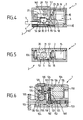
- FIG. 6 Another embodiment of the locking / unlocking device 1 according to the invention, illustrated in FIG. 6, can also, among others, be envisaged.
- the first blade 118 is in one piece. It is attracted to said electromagnet 115 by means of a rod, not shown, sliding in the core of said electromagnet 115.
- said first blade 118 is provided, for example, with an orifice through which said rod is capable of opening, a protuberance being provided at the end of said rod so as to entrain said first blade 118 towards the electri - magnet 115.
- the device according to the invention comprises means 160 to allow locking without power to the coil.
- the spring of said piston 152 is, in particular, provided compressed when the device 1 is in the locked position and able to relax, thus allowing the said first blade 118 to be kept in the unlocked position thanks, for example, to a ring 161 secured to said piston 152 under said first blade 118.
- Said piston 152 is possibly provided in the axis of the movable member 103 and then facilitates unlocking. In fact, said piston, when it relaxes, thus acts on said mobile member 3.
- said piston 152 facilitates the breaking of the bracing between said first blade 118 and said pressure blade 120 and thus authorizes the use of a lower power electromagnet.
- said movable member 103 has at its end a protrusion 155, substantially of the dimensions of said housing 104, extending a rod 156 of reduced size. Such an arrangement facilitates the introduction of said movable member 103 into said housing 104.
- said blocking means 6; 106 are integrated, for example, in a housing 32; 132 formed by said fixed member 2; 102.
- Said housing 32; 132 thus contains, in particular, the electromagnet 15; 115, the blades 18; 118, 20; 120 as well as their axis of articulation 21; 121, 22; 122 and / or the first and second springs 19; 119, 29; 129.
- the reduction in the size of the locking device 1, according to the invention, is thus favored.
- said housing 32; 132 is in particular provided with a removable cover, for example transparent.
- the walls of said housing 32; 132 have, in particular, one or more orifices 33 allowing, for example, the fixing of said housing 32; 132 on its support, such as the tubular frame 7; 107 and / or the fixing, in its internal cavity, of the various elements of the locking means 6; 106.
- Said housing 4; 104 has, for example, the shape of a groove inside which said projection 5; 105 has a transverse opening.
- emergency unlocking means may possibly be provided in the event of a malfunction of the electromagnetic locking means 6. They consist, for example, of a metal rod intended to be introduced by percussion with the inside the housing 32 to unlock the bracing, an imprint on the external surface of said housing 32 can be provided, in particular to facilitate the guiding of said metal rod.
- the present invention also relates to a lock allowing the control by an electric current of a lock or locking / unlocking device such as, in particular, that described above, equipping, in particular removable wall supports, cabinet doors, gates candelables or others.
- said lock may be used, in general, in all sectors of economic activity in which it is necessary to use locks controlled by an electric current.
- the lock according to the invention comprises at least one barrel 201; 301 and a key 202; 302 able to cooperate so as to allow control by an electric current of a lock.
- said barrel 201; 301 and said key 202; 302 are each provided with at least two connection terminals 243; 304, 244; 305, 241; 306, 242; 307, one being connectable to ground, said connection terminals 241; 306, 242; 307 of key 202; 302 being able to be brought into contact with the connection strips 243; 304, 244; 305 of barrel 201; 301.
- said lock comprises an energy source 208, 308 capable of supplying the connection strips of the key 2; 302 or barrel 201; 301 as well as coding means 209; 309 for controlling the lock, said coding relating to bringing said connection terminals 243 into contact; 304, 244; 305, 241; 306, 242; 307 which is only possible in the event of nesting in the barrel 201; 301 of key 202; 302 corresponding to him.
- connection terminals consist, in particular, of flexible blades, capable of establishing contact by deformation one against the other and / or by plugs cooperating with orifices, each provided on the barrel 201; 301 or on the key 202; 302, or vice versa.
- said energy source 208, 308 is provided in the key 202; 302, for example at the level of its gripping zone 210. It consists, for example, of a battery 211, 311.
- said key 202 thus comprises, for example, an electric battery 237, capable of constituting the source of electricity supply necessary here for actuation of the locking / unlocking device 1.
- the fact of providing said battery 237 in said key 202 makes it possible to place the energy source authorizing unlocking at exterior of the installation on which said device 1 according to the invention is fixed and reinforces security.
- said key 202 is provided, for example, with a rod 238 comprising two electrical plugs 239, 240, connected at one end to the terminals of said battery 237, and having, at their opposite end, said two terminals 241, 242, arranged so as to be able to come into contact with said two terminals 243, 244, of given spacing, provided inside said lock 201.
- the spacing that it will therefore be necessary to confer on said terminals 241, 242, provided at the end of said rod 238 in order to actuate said device 1, thus reinforces the reliability of the locking and constitutes coding means 209.
- the housing 32; 132 of the device 1 and said lock can be separated and provided at two different levels in the installations which are equipped with it.
- said lock and said electromagnet 15; 115 are connected, in particular, as mentioned above, by electric cables 45.
- Such a solution also makes it possible to reinforce the reliability of the locking offered by the device according to the invention.
- said socket 301 and said key 302 have, optionally, a longitudinal axis 312 of symmetry.
- Said barrel 301 consists, in particular, of a sleeve 313 and a protuberance 314, provided inside said sleeve 313, said sleeve 313 and said protuberance 314 defining between them a gap 315, by annular example, opening on the side opposite the bottom of said socket 313.
- said lock does not consist of a stator and a rotor movable relative to each other. It therefore has a less complex structure and its implementation is simplified.
- Said key 302 comprises at least, in particular a barrel 316, having a tubular structure, capable of being fitted into said interstice 315.
- Said protuberance 314 is, in particular, made up of a cylinder, the cavity of the sleeve 313 inside which it is provided, being itself, for example, cylindrical. Said protuberance 314 and said cavity are, optionally, coaxial and / or of substantially circular section.
- said barrel 316 has a tubular structure, also possibly cylindrical, in particular of substantially circular section, its thickness being less than that of the gap 315.
- said protuberance 314 may also be hollow, the barrel 316 of the key 302 then having, in correspondence, projections in its own cavity 317.
- connection terminals 304, 305, 306, 307 are provided, in particular, on said barrel 316 and / or in said interstice 315, for example in said cavity 317 and on said protuberance 314.
- Said coding means 309 are constituted, for example, by the relative positioning of the connection terminals 304, 305, 306, 307 on the key 302 and on the socket 301.
- keying pins can also be provided opposite on said key 302 and said lock 301 to indicate the direction of interlocking.
- Said coding means 309 can also be constituted, for example, by the relative dimensions of the barrel 316 and the gap 315, in particular their thickness and / or their depth.
- said coding means 309 can also, for example, consist of cutouts 319, provided on said barrel 316, and extra thicknesses of material 320 provided in correspondence in said interstice 315, or vice versa.
- Said cutouts are constituted, in particular, by slots 319, provided at the end of the barrel 316 and oriented parallel to the longitudinal axis 312, while said extra thicknesses of material are constituted by rods 320, provided at the bottom of said interstice 315 and oriented parallel to the longitudinal axis 312, the dimensions of said cutouts 319 and said rods 320 corresponding to each other, in particular as regards their length.
- said cutouts 319 are provided, in particular, in the thickness of the barrel 316.
- the lock according to the invention may possibly be provided at the level of the barrel 201; 301 and / or the key 202; 302 of a spring element, capable of expelling at least partially, said key 202; 302 of said barrel 201; 301 so as to prevent the electrical connection from lasting too long and running the risk of unnecessarily discharging the energy source.
- the lock controlled by the lock described above may also be constituted, for example, according to embodiments not illustrated, by an electric or electronic component playing the role, in particular, of switch in an electric or electronic circuit .
- Said component is connected, in particular, to the terminals of the barrel.
Landscapes
- Engineering & Computer Science (AREA)
- Structural Engineering (AREA)
- Physics & Mathematics (AREA)
- Electromagnetism (AREA)
- Lock And Its Accessories (AREA)
Abstract
Description
La présente invention concerne un dispositif de verrouillage/déverrouillage du mouvement relatif de deux organes l'un par rapport à l'autre. Elle concerne également une serrure permettant la commande d'un dispositif de verrouillage/déverrouillage tel que, notamment, celui précédemment évoqué.The present invention relates to a device for locking / unlocking the relative movement of two members with respect to each other. It also relates to a lock allowing the control of a locking / unlocking device such as, in particular, that previously mentioned.
Ledit dispositif de verrouillage/déverrouillage et ladite serrure sont notamment destinés à des supports de parois amovibles, des portes de coffrets, des portillons de candélabres ou autres.Said locking / unlocking device and said lock are intended in particular for removable wall supports, cabinet doors, candelabra gates or the like.
Toutefois, bien que plus particulièrement développée pour de telles applications, l'invention pourra également être utilisée dans tous les secteurs de l'activité économique dans lesquels on souhaite bloquer l'accès et/ou empêcher le démontage d'un élément et/ou d'une installation.However, although more particularly developed for such applications, the invention may also be used in all sectors of economic activity in which it is desired to block access and / or prevent the dismantling of an element and / or d 'an installation.
Actuellement, notamment dans le domaine des abris urbains, on est amené à rencontrer des parois constituées généralement de glaces, assujetties à une armature fixe. De telles installations faisant régulièrement l'objet d'actes de vandalisme, lesdites glaces sont souvent abîmées et/ou fracturées, et doivent pouvoir être facilement changées.Currently, especially in the field of urban shelters, we are led to encounter walls generally consisting of windows, subject to a fixed frame. Since such installations are regularly the subject of acts of vandalism, said windows are often damaged and / or fractured, and must be able to be easily changed.
Ainsi, jusqu'à présent, leur fixation était aisément accessible et peu ou mal protégée, facilitant le travail d'éventuels voleurs attirés par leur valeur pécuniaire.Thus, until now, their fixation was easily accessible and poorly or poorly protected, facilitating the work of potential thieves attracted by their monetary value.
En effet, compte tenu de leurs dimensions et de la qualité des matériaux utilisés pour les fabriquer, lesdites glaces sont généralement d'un coût élevé.Indeed, given their dimensions and the quality of the materials used to manufacture them, said glass is generally of high cost.
De telles installations nécessitent donc d'être verrouillées. Pour cela, on connaît de nombreux dispositifs mécaniques différents. Toutefois, dans un tel contexte, ils sont le plus souvent soit trop chers, soit pas assez fiables et les installations sur lesquelles ils sont employés sont alors forcées.Such installations therefore need to be locked. For this, many different mechanical devices are known. However, in such a context, they are most often either too expensive or not reliable enough and the installations on which they are used are then forced.
Le but de la présente invention est de proposer un dispositif de verrouillage/déverrouillage du mouvement relatif de deux organes l'un par rapport à l'autre qui pallie les inconvénients précités en empêchant tout démontage et/ou ouverture des installations sur lesquelles il est utilisé, intempestive non autorisée.The object of the present invention is to provide a device for locking / unlocking the relative movement of two members relative to one another which overcomes the aforementioned drawbacks by preventing any dismantling and / or opening of the installations on which it is used. , untimely unauthorized.
Un autre but de la présente invention est de proposer un dispositif de verrouillage/déverrouillage du mouvement relatif de deux organes l'un par rapport à l'autre qui soit facilement accessible, simple d'utilisation, tout en offrant un niveau de fiabilité et d'inviolabilité satisfaisant.Another object of the present invention is to provide a device for locking / unlocking the relative movement of two members relative to each other which is easily accessible, simple to use, while offering a level of reliability and 'satisfactory inviolability.
Un autre but de la présente invention est de proposer un dispositif de verrouillage/déverrouillage dont l'encombrement soit faible de manière à pouvoir être logé dans un espace de dimensions réduites tel que, par exemple, une armature de support de parois vitrées.Another object of the present invention is to provide a locking / unlocking device whose size is small so that it can be housed in a space of reduced dimensions such as, for example, a support frame for glass walls.
Par ailleurs, on connaît de nombreux types de serrures permettant la commande par un courant électrique d'un dispositif de verrouillage/déverrouillage. Néanmoins, pour certains domaines d'application tels que l'équipement du mobilier urbain, elles sont soit trop complexes, soit pas assez fiables notamment en ce qui concerne les organes, tels que clés et barillets, employés pour leur actionnement.Furthermore, many types of locks are known which allow the control by an electric current of a locking / unlocking device. However, for certain fields of application such as the equipment of street furniture, they are either too complex or not reliable enough in particular with regard to the organs, such as keys and barrels, used for their actuation.
Un autre inconvénient des serrures actuellement connues réside dans le fait qu'elles utilisent des sources d'énergie électriques qui sont prévues à demeure sur l'installation équipée. Ceci n'est pourtant pas toujours souhaitable lorsqu'une telle installation peut être sujette à des détériorations, par exemple dues à des actes de vandalisme.Another drawback of the locks currently known lies in the fact that they use electrical energy sources which are permanently provided on the equipped installation. However, this is not always desirable when such an installation may be subject to deterioration, for example due to acts of vandalism.
Le but de la présente invention est ainsi également de proposer une serrure qui pallie les inconvénients précités et puisse présenter une fiabilité satisfaisante.The object of the present invention is thus also to provide a lock which overcomes the aforementioned drawbacks and can have satisfactory reliability.
Un autre but de la présente invention est de proposer une serrure qui soit simple à utiliser et à mettre en oeuvre.Another object of the present invention is to propose a lock which is simple to use and to implement.
Un autre but de la présente invention est de proposer une serrure permettant la commande par un courant électrique d'un dispositif de verrouillage/déverrouillage dans lequel la source d'énergie utilisée soit extérieure à l'installation équipée dudit dispositif.Another object of the present invention is to provide a lock allowing the control by an electric current of a locking / unlocking device in which the energy source used is external to the installation equipped with said device.
Un autre but de la présente invention est de proposer une serrure permettant la commande électrique d'un dispositif de verrouillage/déverrouillage autorisant un déclenchement à distance de ce dernier.Another object of the present invention is to provide a lock allowing the electrical control of a device for locking / unlocking allowing remote triggering of the latter.
Un autre but de la présente invention est de proposer une serrure qui puisse équiper, notamment, du mobilier urbain tel que des supports de matériau amovibles, des portes de coffrets, des portillons de candélabres ou autres, notamment d'abris bus.Another object of the present invention is to provide a lock which can be fitted, in particular, with street furniture such as removable material supports, cabinet doors, candelabra gates or the like, notably bus shelters.
D'autres buts et avantages de la présente invention apparaîtront au cours de la description qui va suivre qui n'est donnée qu'à titre indicatif et qui n'a pas pour but de la limiter.Other objects and advantages of the present invention will appear during the description which follows which is given only for information and which is not intended to limit it.
La présente invention concerne un dispositif de verrouillage/déverrouillage du mouvement relatif de deux organes l'un par rapport à l'autre, notamment destiné à des supports de parois amovibles, des portes de coffrets, des portillons de candélabres ou autres, caractérisé par le fait qu'il comprend :
- un logement, prévu sur l'un des organes, dit fixe, apte à accueillir l'autre organe, dit mobile,
- une saillie rétractable, apte au moins à déboucher, à travers ledit organe fixe, dans ledit logement, pour coopérer avec ledit organe mobile,
- des moyens électromagnétiques de blocage de ladite saillie dans ledit logement de manière à pouvoir empêcher le déplacement relatif dudit organe mobile, en position de verrouillage.
- a housing, provided on one of the members, said to be fixed, capable of accommodating the other member, said to be mobile,
- a retractable projection, able at least to open, through said fixed member, into said housing, to cooperate with said movable member,
- electromagnetic means for blocking said projection in said housing so as to be able to prevent the relative displacement of said movable member, in the locked position.
La présente invention concerne également une serrure comprenant au moins un barillet et une clé, aptes à coopérer de façon à permettre la commande d'un dispositif de verrouillage/déverrouillage par un courant électrique, caractérisée par le fait que :
- ledit barillet et ladite clé sont munis chacun d'au moins deux bornes de connexion, les bornes de connexion de la clé étant aptes à être mises en contact avec les bornes de connexion du barillet,
- ladite serrure comprend une source d'énergie, apte à alimenter les bornes de connexion de la clé ou du barillet, et des moyens de codage de la commande, ledit codage portant sur la mise en contact desdites bornes de connexion, prévu possible qu'en cas d'emboîtement dans le barillet de la clé lui correspondant.
- said barrel and said key are each provided with at least two connection terminals, the connection terminals of the key being able to be brought into contact with the connection terminals of the barrel,
- said lock comprises a power source, capable of supplying the connection terminals of the key or of the barrel, and means for coding the command, said coding relating to bringing said contacts into contact connection terminals, possible only if it fits into the barrel of the corresponding key.
La présente invention sera mieux comprise à la lecture de la description suivante accompagnée des dessins en annexe qui en font partie intégrante et parmi lesquels :
- la figure 1 est une vue de dessus, en coupe, d'un premier exemple de dispositif de verrouillage/déverrouillage conforme à l'invention, en cours de déverrouillage,
- la figure 2 décrit, selon la même vue, le dispositif illustré à la figure 1, en position de verrouillage,
- la figure 3 est une vue latérale, en coupe, de l'exemple de dispositif illustré aux figures 1 et 2 précédentes,
- la figure 4 décrit, selon un plan de coupe longitudinal, un second exemple de dispositif de verrouillage/déverrouillage conforme à l'invention,
- la figure 5 est une vue de dessus, en coupe, d'après la figure 4,
- la figure 6 décrit, selon un plan de coupe longitudinal, un troisième exemple de dispositif de verrouillage/déverrouillage conforme à l'invention,
- la figure 7 est une vue latérale, en coupe, illustrant le principe d'actionnement par un exemple de serrure conforme à l'invention du dispositif de verrouillage/déverrouillage, illustré aux figures 1 à 3 précédentes,
- la figure 8 est une vue de dessus d'après la figure 4,
- la figure 9 décrit, selon une coupe radiale, un autre exemple de réalisation de serrure conforme à l'invention,
- la figure 10 décrit, selon une coupe radiale, un exemple encore différent de réalisation de serrure conforme à l'invention,
- la figure 11 est une vue en perspective, selon une coupe radiale de la serrure illustrée à la figure 10 précédente, le plan de coupe étant orienté de manière différente.
- FIG. 1 is a top view, in section, of a first example of a locking / unlocking device according to the invention, during unlocking,
- FIG. 2 describes, according to the same view, the device illustrated in FIG. 1, in the locked position,
- FIG. 3 is a side view, in section, of the example of device illustrated in the preceding FIGS. 1 and 2,
- FIG. 4 describes, according to a longitudinal sectional plane, a second example of a locking / unlocking device according to the invention,
- FIG. 5 is a top view, in section, according to FIG. 4,
- FIG. 6 describes, according to a longitudinal section plane, a third example of a locking / unlocking device according to the invention,
- FIG. 7 is a side view, in section, illustrating the principle of actuation by an example of a lock in accordance with the invention of the locking / unlocking device, illustrated in preceding figures 1 to 3,
- FIG. 8 is a top view according to FIG. 4,
- FIG. 9 describes, in a radial section, another exemplary embodiment of a lock according to the invention,
- FIG. 10 describes, in a radial section, a still different example of embodiment of a lock according to the invention,
- Figure 11 is a perspective view, in a radial section of the lock illustrated in Figure 10 above, the cutting plane being oriented differently.
La présente invention concerne tout d'abord un dispositif de verrouillage/déverrouillage du mouvement relatif de deux organes l'un par rapport à l'autre, notamment destiné à des supports de parois amovibles, des portes de coffrets, des portillons de candélabres ou autres.The present invention relates first of all to a device for locking / unlocking the relative movement of two members relative to one another, in particular intended for removable wall supports, cabinet doors, candelabra gates or the like .
De telles applications ne sont toutefois pas limitatives et ledit dispositif de verrouillage/déverrouillage pourra également être utilisé dans tous les secteurs de l'activité économique dans lesquels on souhaite bloquer l'accès et/ou empêcher le démontage d'une installation.However, such applications are not limiting and said locking / unlocking device can also be used in all sectors of economic activity in which it is desired to block access and / or prevent the dismantling of an installation.
Comme illustré aux figures 1 à 6, le dispositif 1 de verrouillage/déverrouillage du mouvement relatif de deux organes 2 ; 102, 3 ; 103 l'un par rapport à l'autre, conforme à l'invention, comprend un logement 4 ; 104 prévu sur l'un des organes 2 ; 102, dit fixe, ledit logement 4 ; 104 étant apte à accueillir l'autre organe 3 ; 103, dit mobile.As illustrated in Figures 1 to 6, the
Le dispositif 1 comprend également une saillie 5 ; 105 rétractable, apte au moins à déboucher, à travers ledit organe fixe 2 ; 102 dans ledit logement 4 ; 104 pour coopérer avec ledit organe mobile 3 ; 103.The
De manière à pouvoir empêcher le déplacement relatif dudit organe mobile lorsqu'il est en position de verrouillage, le dispositif 1 comprend des moyens électromagnétiques 6 ; 106 de blocage de ladite saillie 5 ; 105 dans ledit logement 4 ; 104.In order to be able to prevent the relative displacement of said movable member when it is in the locked position, the
On donne dans la suite quelques exemples non limitatifs d'application du dispositif 1 conformes à l'invention.Some non-limiting examples of application of the
Aux figures 1 à 3, ledit dispositif 1 est logé dans une armature tubulaire 7 et permet de maintenir une paroi amovible 8 telle que, notamment, une glace. Pour cela, ledit organe fixe 2 et ledit organe mobile forment, par exemple, en position de verrouillage, une gorge 9 à leur extrémité prévue à l'opposé de ladite armature tubulaire 7, dans laquelle gorge 9 la dite paroi amovible 8 est apte à être introduite.In Figures 1 to 3, said
Selon l'invention, ledit organe mobile 3 peut être déplacé, par exemple, selon la direction de la flèche repérée 10, de manière à être retiré dudit logement 4. La paroi amovible 8 peut alors être installée ou déposée avant de remettre ledit organe mobile 3 dans ledit logement 4 et assurer ainsi la formation de la gorge 9 après verrouillage.According to the invention, said
Si l'on se reporte maintenant aux figures 7 et 8, on observe un autre exemple d'application du dispositif 1 conforme à l'invention à un coffret ou candélabre 11 dont il permet le blocage de la porte ou portillon 12.If we now refer to FIGS. 7 and 8, there is another example of application of the
Pour cela, l'organe fixe 2 est assujetti aux parois 13 dudit coffret 11 tandis que l'organe mobile 3 est assujetti à ladite porte 12 et peut être déplacé, lorsque le dispositif est déverrouillé, selon le sens de la flèche repérée 14.For this, the fixed
Si l'on revient maintenant au dispositif 1 en tant que tel, on constate que, selon les modes de réalisation illustrés, lesdits moyens électromagnétiques de blocage 6 ; 106, sont constitués au moins par un électro-aimant 15 ; 115, assujetti directement ou indirectement audit organe fixe 2 ; 102. Ledit électro-aimant 15 ; 115 est apte, notamment, à permettre le déverrouillage lorsqu'il est parcouru par un courant, le dispositif étant maintenu verrouillé dans le cas inverse. ll est constitué, par exemple, d'une bobine 16 et d'un noyau 17.If we now return to the
Lesdits moyens de blocage 6 comprennent, en outre, notamment, une première lame 18 ; 118 mobile, assujettie directement ou indirectement audit organe fixe 2 ; 102. Ladite première lame 18 ; 118 est apte, par exemple, à bloquer directement ou indirectement la saillie 5; 105 dans ledit logement 4 ; 104 en position de verrouillage et/ou sous l'effet du champ magnétique créé par l'électro-aimant 15 ; 115, à laisser libre ladite saillie 5 ;105 dans le cas inverse.Said locking means 6 further comprise, in particular, a
Lorsque l'électro-aimant 15 ; 115 est parcouru par un courant, ladite première lame 18 ; 118 est ainsi notamment, attirée vers ledit élément aimant 15; 115.When the
Comme plus spécialement représentés aux figures 1 et 2, ainsi que 4 et 6, lesdits moyens de blocage 6 ; 106 comprennent, en outre, éventuellement, un premier ressort 19 ; 119, assujetti directement ou indirectement audit organe fixe 2 ; 102 coopérant avec ladite première lame 18 ; 118 pour assurer le verrouillage. Ledit ressort 19 ; 119 permet ainsi, par exemple, de repousser ladite première lame 18 ; 118 de l'électro-aimant 15 ; 115 lorsque ce dernier n'est plus alimenté.As more especially shown in Figures 1 and 2, as well as 4 and 6, said locking means 6; 106 further comprises, optionally, a
Selon le mode de réalisation illustré, lesdits moyens de blocage 6 ; 106 comprennent, en outre, une seconde lame, dite lame de pression 20 ; 120, mobile, assujettie directement ou indirectement audit organe fixe 2 ; 102. Ladite lame de pression 20 ; 120 coopère, par exemple, avec ladite saillie 5 ; 105. De plus, elle est apte à être immobilisée par arc-boutement contre ladite première lame 18 ; 118 lorsque ledit dispositif 1 est en position de verrouillage.According to the illustrated embodiment, said blocking means 6; 106 further comprise a second blade, called the
Lesdites premières lame 18 ; 118 et lame de pression 20 ; 120 sont, par exemple, mobiles en rotation, respectivement, autour d'un premier 21 ; 121 et d'un second 22 ; 122 axes, assujettis à l'organe fixe 2 ; 102.Said
Ladite lame de pression 20 ; 120 présente, notamment, une extrémité coopérant avec ladite première lame 18 ; 118 munie d'un bec 23 ; 123.Said
Ce dernier comprend, d'une part, une arête 24 ; 124 formant notamment une pente abrupte favorisant l'arc-boutement contre ladite première lame 18 ; 118.The latter comprises, on the one hand, an
D'autre part, il est à noter que, lors d'un déverrouillage, ladite lame de pression 20 est poussée en retrait par la saillie rétractable 5 sous l'action des déplacements de l'organe mobile 3 dans ledit logement 4, comme il est représenté à la figure 1.On the other hand, it should be noted that, during unlocking, said
Si, selon le mode de réalisation illustré à cette figure, lorsque ladite lame de pression 20 est dans une telle position de retrait, l'alimentation de l'électro-aimant 15 vient à être coupée, la première lame 18, repoussée par le premier ressort 19, pourra alors bloquer le dispositif 1 en position déverrouillée.If, according to the embodiment illustrated in this figure, when said
Afin de pallier cet éventuel inconvénient, ledit bec 23 présente donc, par exemple, une arête 25, formant une pente douce, permettant d'éviter un tel blocage intempestif du dispositif 1 en positon déverrouillée en cas de coupure de l'alimentation de l'électro-aimant 15 lors dudit déverrouillage.In order to overcome this possible drawback, said
Cela étant, selon les modes de réalisation illustrés, la première lame 18 ; 118 présente un épaulement 26 ; 126, apte à coopérer avec l'arête abrupte 24 ; 124 de la lame de pression 20 ; 120 afin de favoriser également l'arc-boutement.However, according to the illustrated embodiments, the
Ledit épaulement 26 ; 126 est prévu, sur ladite première lame 18 ; 118, par exemple, en vis-à-vis de ladite arête douce 25 ; 125 de la lame de pression 20 ; 120 lorsque cette dernière est en position de retrait. On évitera ainsi les éventuels risques de blocage évoqués plus haut.Said
Selon le premier mode de réalisation illustré, ladite première lame 18 est éventuellement constituée de deux éléments distincts 27, 28 assujettis l'un à l'autre et se déplaçant conjointement. Le premier élément 27 est formé, par exemple, d'un matériau magnétique et permet la coopération avec l'électro-aimant 15 tandis que le second élément 28 est formé, par exemple, d'un matériau plus robuste, apte à favoriser l'arc-boutement contre la lame de pression 20.According to the first illustrated embodiment, said
Lesdits moyens de blocage 6 ; 106 comprennent, en outre, éventuellement un second ressort 29 ; 129, assujetti directement ou indirectement audit organe fixe 2 ; 102. Ledit second ressort 29 ; 129 coopère avec ladite lame de pression 20 ; 120 de manière à permettre le retour de ladite saillie 5 ; 105 dans ledit logement 4 ; 104. Ainsi, lorsque ladite lame de pression 20 ; 120 est dans la position de retrait évoquée plus haut, ledit second ressort 29 ; 129 exerce un effort de rappel et repousse ladite lame de pression 20 ; 120 en direction dudit logement 4 ; 104 en position de verrouillage. Il en est de même, éventuellement, lorsque l'organe mobile 3 a été extrait dudit logement 4.Said locking means 6; 106 further comprises, optionally, a
A ce sujet, ledit organe mobile 3 ; 103 présente, éventuellement, un évidement 30 ; 130 dans lequel ladite saillie 5 ; 105 est apte à s'encastrer, en position de verrouillage. Quant à ladite saillie 5 ; 105, elle est constituée, notamment, par un cliquet, coulissant dans un orifice 31 ; 131 prévu sur ledit organe fixe 2 ; 102.In this regard, said
Une telle disposition permet ainsi de séparer ledit organe mobile 3 ; 103 des lames permettant le verrouillage. Lors d'un essai frauduleux de déverrouillage par traction sur ledit organe mobile 3 ; 103, celui-ci se répercute donc sur le cliquet 5 ; 105 logé dans ledit orifice 31 ; 131 plutôt que sur lesdites lames 18 ; 118, 20 ; 120 qui sont elles plus fragiles. La fiabilité du dispositif conforme à l'invention est ainsi renforcée.Such an arrangement thus makes it possible to separate said
Ledit cliquet 5 ; 105 est formé, par exemple d'une bille, apte à s'encastrer comme évoqué plus haut, dans ledit évidement 30, 130 prévu sensiblement hémisphérique.
Comme illustré aux figures 4 et 5, le dispositif de verrouillage décrit plus haut pourra également comprendre, éventuellement, de manière supplémentaire, un levier 53, articulé en rotation autour d'un axe 54 assujetti audit organe fixe 2. Ledit levier 53, prévu apte à coopérer avec ledit organe mobile 3 permet, notamment, de pouvoir réintroduire ce dernier à l'intérieur dudit logement 4 même lorsque ladite première lame 18 n'est pas attirée par l'électro-aimant 15, ce qui était le cas dans le mode de réalisation illustré aux figures 1 à 3 pour lequel il fallait alimenter la bobine pour pouvoir reverrouiller.As illustrated in FIGS. 4 and 5, the locking device described above may also include, possibly, additionally, a
En effet, lors de cette phase, l'une des extrémités 56 dudit levier 53 est apte à coopérer avec l'extrémité distale 55 dudit organe mobile 3, l'autre extrémité 57 dudit levier 53 étant alors apte à débloquer ladite première lame 18.In fact, during this phase, one of the
De plus, pour ne pas géner le verrouillage, ledit organe mobile 3 présente une découpe 58 dans laquelle ladite extrémité 56 dudit levier 53 est apte à se loger.In addition, so as not to generate the locking, said
Un piston 60 pourra également être prévu dans ledit dispositif 1 conforme à l'invention afin de faciliter, par effet ressort, le déverrouillage de l'organe bloqué par ledit élément mobile 3.A piston 60 could also be provided in said
Cela étant, un autre mode de réalisation du dispositif de verrouillage/déverrouillage 1 conforme à l'invention, illustré à la figure 6, peut également, parmi d'autres, être envisagé.However, another embodiment of the locking / unlocking
Dans ce mode de réalisation, la première lame 118 est monobloc. Elle est attirée par ledit électro-aimant 115 par l'intermédiaire d'une tige, non-représentée, coulissant dans le noyau dudit électro-aimant 115.In this embodiment, the
Pour cela, ladite première lame 118 est munie, par exemple, d'un orifice à travers lequel ladite tige est apte à déboucher, une protubérance étant prévue à l'extrémité de ladite tige de manière à entraîner ladite première lame 118 vers l'électri-aimant 115.For this, said
Par ailleurs, comme cela est également le cas pour le mode de réalisation illustré aux figures 4 et 5, le dispositif conforme à l'invention comprend des moyens 160 pour permettre le verrouillage sans alimentation de la bobine.Furthermore, as is also the case for the embodiment illustrated in Figures 4 and 5, the device according to the invention comprises means 160 to allow locking without power to the coil.
Il s'agit ici, par exemple, d'un piston 152, apte à maintenir la première lame 118 en position de déverrouillage. Pour cela, le ressort dudit piston 152 est, notamment, prévu comprimé lorsque le dispositif 1 est en position de verrouillage et apte à se détendre permettant alors le maintien de la dite première lame 118 en position déverrouillée grâce, par exemple, à une bague 161 assujettie audit piston 152 sous ladite première lame 118.This is, for example, a
Ledit piston 152 est, éventuellement, prévu dans l'axe de l'organe mobile 103 et facilite alors le déverrouillage. En effet, ledit piston, lors de sa détente, agit ainsi sur ledit organe mobile 3.
Il est également à noter que l'utilisation dudit piston 152 facilite la rupture de l'arc-boutement entre ladite première lame 118 et ladite lame de pression 120 et autorise ainsi l'emploi d'un électro-aimant de plus faible puissance.It should also be noted that the use of said
Enfin, selon ce mode de réalisation, ledit organe mobile 103 présente à son extrémité une protubérance 155, sensiblement des dimensions dudit logement 104, prolongeant une tige 156 de dimension réduite. Une telle disposition facilite l'introduction dudit organe mobile 103 dans ledit logement 104.Finally, according to this embodiment, said
Cela étant, selon les différents modes de réalisation illsutrés, lesdits moyens de blocage 6 ; 106 sont intégrés, par exemple, dans un boîtier 32 ; 132 formé par ledit organe fixe 2 ; 102. Ledit boîtier 32 ; 132 renferme ainsi, notamment, l'électro-aimant 15 ; 115, les lames 18 ; 118, 20 ; 120 ainsi que leur axe d'articulation 21 ; 121, 22 ; 122 et/ou les premier et deuxième ressorts 19 ; 119, 29 ; 129. La diminution de l'encombrement du dispositif 1 de verrouillage, conforme à l'invention, est ainsi favorisée.However, according to the different embodiments illustrated, said blocking means 6; 106 are integrated, for example, in a
Par ailleurs, afin de simplifier sa fabrication, ledit boîtier 32 ; 132 est notamment muni d'un couvercle amovible, par exemple transparent. Les parois dudit boîtier 32 ; 132 présentent, notamment, un ou plusieurs orifices 33 permettant, par exemple, la fixation dudit boîtier 32 ; 132 sur son support, tel que l'armature tubulaire 7 ; 107 et/ou la fixation, dans sa cavité intérieure, des différents éléments des moyens de blocage 6 ; 106.Furthermore, in order to simplify its manufacture, said
Ledit logement 4 ; 104 présente, par exemple, la forme d'une gorge à l'intérieur de laquelle ladite saillie 5 ; 105 est débouchante transversalement.Said
A titre de remarque, il est à noter que des moyens de déverrouillage de secours peuvent être éventuellement prévus en cas de disfonctionnement des moyens électromagnétiques de blocage 6. Ils sont constitués, par exemple, par une tige métallique destinée à être introduite par percussion à l'intérieur du boîtier 32 pour débloquer l'arc-boutement, une empreinte sur la surface extérieure dudit boîtier 32 pouvant être prévue, notamment pour faciliter le guidage de ladite tige métallique.By way of a note, it should be noted that emergency unlocking means may possibly be provided in the event of a malfunction of the electromagnetic locking means 6. They consist, for example, of a metal rod intended to be introduced by percussion with the inside the
La présente invention concerne également une serrure permettant la commande par un courant électrique d'un verrou ou dispositif de verrouillage/déverrouillage tel que, notamment, celui exposé plus haut, équipant, notamment des supports de parois amovibles, des portes de coffrets, des portillons de candélables ou autres.The present invention also relates to a lock allowing the control by an electric current of a lock or locking / unlocking device such as, in particular, that described above, equipping, in particular removable wall supports, cabinet doors, gates candelables or others.
Toutefois, bien que plus particulièrement prévue pour de telles applications, ladite serrure pourra être utilisée, de manière générale, dans tous les secteurs de l'activité économique dans lesquels on est amené à employer des verrous commandés par un courant électrique.However, although more particularly intended for such applications, said lock may be used, in general, in all sectors of economic activity in which it is necessary to use locks controlled by an electric current.
Comme représentée aux figures 7 à 11, la serrure conforme à l'invention comprend au moins un barillet 201 ; 301 et une clé 202 ; 302 aptes à coopérer de façon à permettre la commande par un courant électrique d'un verrou.As shown in Figures 7 to 11, the lock according to the invention comprises at least one barrel 201; 301 and a key 202; 302 able to cooperate so as to allow control by an electric current of a lock.
Selon l'invention, ledit barillet 201 ; 301 et ladite clé 202 ; 302 sont munis chacun d'au moins deux bornes de connexion 243 ; 304, 244 ; 305, 241 ; 306, 242 ; 307, l'une pouvant être reliée à la masse, lesdites bornes de connexion 241 ; 306, 242 ; 307 de la clé 202 ; 302 étant aptes à être mises en contact avec les bandes de connexion 243 ; 304, 244 ; 305 du barillet 201 ; 301.According to the invention, said barrel 201; 301 and said key 202; 302 are each provided with at least two
De plus, ladite serrure comprend une source d'énergie 208, 308 apte à alimenter les bandes de connexion de la clé 2 ; 302 ou du barillet 201 ; 301 ainsi que des moyens de codage 209 ; 309 de la commande du verrou, ledit codage concernant la mise en contact desdites bornes de connexion 243 ; 304, 244 ; 305, 241 ; 306, 242 ; 307 qui n'est possible qu'en cas d'emboîtement dans le barillet 201 ; 301 de la clé 202 ; 302 lui correspondant.In addition, said lock comprises an
Ainsi, lorsque la bonne clé 202 ; 302 est utilisée, il y a fermeture du circuit électrique défini entre le barillet 201 ; 301 et ladite clé 202 ; 302. On dispose alors, grâce à la source d'énergie 208, 308 employée, d'un courant qui peut être utilisé directement ou indirectement pour la commande du verrou tel que, notamment le dispositif de verrouillage/déverrouillage 1 précédemment décrit, par exemple pour alimenter en courant électrique l'électro-aimant 15 ; 115 par l'intermédiaire d'un câblage 45.So when the
Lesdites bornes de connexion sont constituées, notamment, de lames flexibles, aptes à établir un contact par déformation l'une contre l'autre et/ou par des fiches coopérant avec des orifices, prévus chacun soit sur le barillet 201 ; 301 ou sur la clé 202 ; 302, ou réciproquement.Said connection terminals consist, in particular, of flexible blades, capable of establishing contact by deformation one against the other and / or by plugs cooperating with orifices, each provided on the barrel 201; 301 or on the key 202; 302, or vice versa.
Selon un mode de réalisation préférentiel, ladite source d'énergie 208, 308 est prévue dans la clé 202 ; 302, par exemple au niveau de sa zone de préhension 210. Elle est constituée, par exemple, d'une batterie 211, 311.According to a preferred embodiment, said
Si l'on se reporte maintenant plus spécialement à la figure 7, on constate que ladite clé 202 comprend ainsi, par exemple, une pile électrique 237, apte à constituer la source d'alimentation en électricité nécessaire ici à l'actionnement du dispositif de verrouillage/déverrouillage 1. Le fait de prévoir ladite pile 237 dans ladite clé 202 permet de placer la source d'énergie autorisant le déverrouillage à l'extérieur de l'installation sur laquelle ledit dispositif 1 conforme à l'invention est fixé et renforce la sécurité.If we now refer more particularly to FIG. 7, it can be seen that said key 202 thus comprises, for example, an
De plus, ladite clé 202 est munie, par exemple, d'une tige 238 comprenant deux fiches électriques 239, 240, reliées à l'une de leur extrémité aux bornes de ladite pile 237, et présentant, à leur extrémité opposée, lesdites deux bornes 241, 242, disposées de manière à pouvoir rentrer en contact avec lesdites deux bornes 243, 244, d'espacement donné, prévu à l'intérieur de ladite serrure 201. Outre le profil éventuellement spécial donné à ladite tige 238, l'espacement qu'il sera donc nécessaire de conférer auxdites bornes 241, 242, prévu à l'extrémité de ladite tige 238 pour actionner ledit dispositif 1 renforce ainsi la fiabilité du verrouillage et constitue des moyens de codage 209.In addition, said key 202 is provided, for example, with a
Il est également à noter que le boîtier 32 ; 132 du dispositif 1 et ladite serrure peuvent être dissociés et prévus à deux niveaux différents dans les installations qui en sont équipées. Pour cela, ladite serrure et ledit électro-aimant 15 ; 115 sont reliés, notamment, comme évoqué plus haut, par des câbles électriques 45. Une telle solution permet également de renforcer la fiabilité du verrouillage offerte par le dispositif conforme à l'invention.It should also be noted that the
Dans le cas de l'application de l'invention au verrouillage de parois amovibles, notamment d'abris bus, leurs supports sont munis, notamment, de deux dispositifs de verrouillage conformes à l'invention, accompagnés de leurs serrures, leurs clés étant éventuellement identiques.In the case of the application of the invention to the locking of removable walls, in particular bus shelters, their supports are provided, in particular, with two locking devices in accordance with the invention, accompanied by their locks, their keys possibly being identical.
En se reportant maintenant aux figures 9 et 10, on constate que ladite douille 301 et ladite clé 302 présentent, éventuellement, un axe longitudinal 312 de symétrie.Referring now to Figures 9 and 10, we see that said
Ledit barillet 301 est constitué, notamment, d'une douille 313 et d'une protubérance 314, prévues à l'intérieur de ladite douille 313, ladite douille 313 et ladite protubérance 314 définissant entre elles un interstice 315, par exemple annulaire, débouchant du côté opposé au fond de ladite douille 313.Said
Contrairement à ce que l'on trouve dans la plupart des dispositifs de verrouillage, notamment mécaniques, connus, ladite serrure n'est pas constituée d'un stator et d'un rotor mobiles l'un par rapport à l'autre. Elle présente donc une structure moins complexe et sa mise en oeuvre est simplifiée.Contrary to what is found in most locking devices, in particular mechanical, known, said lock does not consist of a stator and a rotor movable relative to each other. It therefore has a less complex structure and its implementation is simplified.
Ladite clé 302 comprend au moins, notamment un canon 316, présentant une structure tubulaire, apte à être emboîtée dans ledit interstice 315.Said key 302 comprises at least, in particular a
Ladite protubérance 314 est, notamment, constituée d'un cylindre, la cavité de la douille 313 à l'intérieur de laquelle elle est prévue, étant elle-même, par exemple, cylindrique. Ladite protubérance 314 et ladite cavité sont, éventuellement, coaxiales et/ou de section sensiblement circulaire.
De son côté, ledit canon 316 présente une structure tubulaire, elle aussi éventuellement cylindrique, notamment de section sensiblement circulaire, son épaisseur étant inférieure à celle de l'interstice 315.For its part, said
L'utilisation d'une section circulaire permet, notamment, larotation de la clé 302 dans le barillet 301.The use of a circular section allows, in particular, the rotation of the key 302 in the
Cela étant, selon des exemples de réalisation non représentés, ladite protubérance 314 pourra être creuse elle aussi, le canon 316 de la clé 302 présentant alors, en correspondance, des saillies dans sa propre cavité 317.However, according to embodiments not shown, said
Lesdites bornes de connexion 304, 305, 306, 307 sont prévues, notamment, sur ledit canon 316 et/ou dans ledit interstice 315, par exemple dans ladite cavité 317 et sur ladite protubérance 314.Said
Lesdits moyens de codage 309 sont constitués, par exemple, par le positionnement relatif des bornes de connexion 304, 305, 306, 307 sur la clé 302 et sur la douille 301. Afin de faciliter la mise en contact lors de l'utilisation de la bonne clé 302, des détrompeurs peuvent être d'ailleurs prévus en vis-à-vis sur ladite clé 302 et ladite serrure 301 pour indiquer la direction d'emboîtement.Said coding means 309 are constituted, for example, by the relative positioning of the
Lesdits moyens de codage 309 peuvent être également constitués, par exemple, par les dimensions relatives du canon 316 et de l'interstice 315, notamment leur épaisseur et/ou leur profondeur.Said coding means 309 can also be constituted, for example, by the relative dimensions of the
Concernant l'épaisseur, il est à noter que la correspondance des dimensions dudit canon 316 et dudit interstice 315 dans cette direction favorisera l'établissement de la connexion entre lesdites bornes 304, 305, 306, 307, notamment dans le cas d'utilisation, comme évoqué plus haut, de lames flexibles. Des rails de guidage 318 desdites bandes de connexion 306, 307 de la clé 302 sont éventuellement prévus au niveau de la surface de ladite protubérance 314.Regarding the thickness, it should be noted that the correspondence of the dimensions of said
Comme plus particulièrement illustrés aux figures 10 et 11, lesdits moyens de codage 309 peuvent encore, par exemple, être constitués de découpes 319, prévues sur ledit canon 316, et de surépaisseurs de matières 320 prévues en correspondance dans ledit interstice 315, ou réciproquement.As more particularly illustrated in FIGS. 10 and 11, said coding means 309 can also, for example, consist of
Lesdites découpes sont constituées, notamment, par des fentes 319, prévues à l'extrémité du canon 316 et orientées parallèlement à l'axe longitudinal 312, tandis que lesdites surépaisseurs de matière sont constituées par des tiges 320, prévues au fond dudit interstice 315 et orientées parallèlement à l'axe longitudinal 312, les dimensions desdites découpes 319 et desdites tiges 320 correspondant entre elles, notamment en ce qui concerne leur longueur.Said cutouts are constituted, in particular, by
Comme représentées, lesdites découpes 319 sont prévues, notamment, dans l'épaisseur du canon 316.As shown, said
Cela étant, la serrure conforme à l'invention pourra éventuellement être munie au niveau du barillet 201 ; 301 et/ou de la clé 202 ; 302 d'un élément ressort, apte à expulser au moins partiellement, ladite clé 202 ; 302 dudit barillet 201 ; 301 de manière à éviter que la connexion électrique ne dure trop longtemps et risque de décharger inutilement la source d'énergie.However, the lock according to the invention may possibly be provided at the level of the barrel 201; 301 and / or the key 202; 302 of a spring element, capable of expelling at least partially, said key 202; 302 of said barrel 201; 301 so as to prevent the electrical connection from lasting too long and running the risk of unnecessarily discharging the energy source.
En effet, ce que l'on souhaite obtenir de la serrure conforme à l'invention n'est pas forcément l'établissement d'un courant électrique permanent mais plutôt, notamment dans le cas du dispositif de verrouillage/déverrouillage précédemment décrit, une impulsion, apte à entraîner un changement d'état dudit dispositif.Indeed, what is desired from the lock according to the invention is not necessarily the establishment of an electric current permanent but rather, in particular in the case of the previously described locking / unlocking device, an impulse capable of causing a change of state of said device.
Concernant ce dernier, le verrou commandé par la serrure décrite plus haut pourra également être constitué, par exemple, selon des modes de réalisation non illustrés, par un composant électrique ou électronique jouant le rôle, notamment, d'interrupteur dans un circuit électrique ou électronique. Ledit composant est connecté, notamment, aux bornes du barillet. Ainsi, lorsque les bornes de connexion de la clé sont mises en contact avec celles dudit barillet, ledit composant peut être déclenchéRegarding the latter, the lock controlled by the lock described above may also be constituted, for example, according to embodiments not illustrated, by an electric or electronic component playing the role, in particular, of switch in an electric or electronic circuit . Said component is connected, in particular, to the terminals of the barrel. Thus, when the connection terminals of the key are brought into contact with those of said barrel, said component can be triggered
Naturellement, d'autres modes de mise en oeuvre, à la portée de l'homme de l'art, auraient pu être envisagés sans pour autant sortir du cadre de la présente invention.Naturally, other modes of implementation, within the reach of those skilled in the art, could have been envisaged without departing from the scope of the present invention.
Claims (10)
Applications Claiming Priority (2)
| Application Number | Priority Date | Filing Date | Title |
|---|---|---|---|
| FR9607244A FR2749606B1 (en) | 1996-06-06 | 1996-06-06 | DEVICE FOR LOCKING THE RELATIVE MOTION OF TWO ORGANS IN RELATION TO ONE ANOTHER, IN PARTICULAR FOR REMOVABLE WALL SUPPORTS, CASE DOORS, CANDELABRA GATES OR THE LIKE |
| FR9607244 | 1996-06-06 |
Publications (1)
| Publication Number | Publication Date |
|---|---|
| EP0811738A1 true EP0811738A1 (en) | 1997-12-10 |
Family
ID=9492945
Family Applications (1)
| Application Number | Title | Priority Date | Filing Date |
|---|---|---|---|
| EP97490017A Withdrawn EP0811738A1 (en) | 1996-06-06 | 1997-06-06 | Locking device |
Country Status (2)
| Country | Link |
|---|---|
| EP (1) | EP0811738A1 (en) |
| FR (1) | FR2749606B1 (en) |
Cited By (10)
| Publication number | Priority date | Publication date | Assignee | Title |
|---|---|---|---|---|
| DE19801752C1 (en) * | 1998-01-20 | 1999-05-12 | Dorma Gmbh & Co Kg | Locking device for emergency exit doors |
| WO2007034474A1 (en) * | 2005-09-19 | 2007-03-29 | Meteoronics Ltd | Electric locks with release hammer |
| WO2011023187A3 (en) * | 2009-08-27 | 2011-05-19 | Tap Ltd. | Lock |
| US20140338408A1 (en) * | 2013-05-14 | 2014-11-20 | Asustek Computer Inc. | Electronic system with locking function by electronically controlled |
| US20150021926A1 (en) * | 2013-07-19 | 2015-01-22 | Amsafe Commercial Products, Inc. | Latch device and anchor with swivel coupling |
| FR3036421A1 (en) * | 2015-05-20 | 2016-11-25 | Kendrion Kuhnke Automation Gmbh | DEVICE FOR LOCKING A RETAINING FINGER CONNECTED TO A COVER |
| US20170254119A1 (en) * | 2016-03-03 | 2017-09-07 | Dan Raz Ltd. | Latch arrangement having a stop latch |
| US10480213B2 (en) | 2015-11-29 | 2019-11-19 | Dan Raz Ltd. | Door or other closable panel with lock-actuating linkage |
| US10822837B2 (en) | 2017-09-03 | 2020-11-03 | Dan Raz Ltd. | Obliquely-engaging locking mechanism |
| US10865588B2 (en) | 2015-08-24 | 2020-12-15 | Dan Raz Ltd. | Securing mechanism for a sliding panel |
Citations (6)
| Publication number | Priority date | Publication date | Assignee | Title |
|---|---|---|---|---|
| FR15078E (en) * | 1909-07-16 | 1912-04-20 | Gustave Sahmer | Electric locking and unlocking device for deadbolt locks |
| DE284194C (en) * | 1914-02-13 | 1915-05-14 | Beckmann Albert | LOCK PROTECTION WITH A BOLT-ENGAGING, ELECTRICALLY RELEASED PATCH |
| DE386544C (en) * | 1921-06-19 | 1923-12-11 | Hugo Klostermann | Electromagnetic door lock |
| DE433321C (en) * | 1923-08-31 | 1926-09-01 | Internationales Handelsbuero F | Electric lock security |
| EP0096400A2 (en) * | 1982-06-07 | 1983-12-21 | ELEKTRONIKBAU Krippner & Kletzmaier Gesellschaft m.b.H. & Co. | Lock installation for securing doors |
| FR2624904A1 (en) * | 1987-12-16 | 1989-06-23 | Vesnitch Yves | Simplified lock for sliding or pivoting closure with fire safety |
-
1996
- 1996-06-06 FR FR9607244A patent/FR2749606B1/en not_active Expired - Fee Related
-
1997
- 1997-06-06 EP EP97490017A patent/EP0811738A1/en not_active Withdrawn
Patent Citations (6)
| Publication number | Priority date | Publication date | Assignee | Title |
|---|---|---|---|---|
| FR15078E (en) * | 1909-07-16 | 1912-04-20 | Gustave Sahmer | Electric locking and unlocking device for deadbolt locks |
| DE284194C (en) * | 1914-02-13 | 1915-05-14 | Beckmann Albert | LOCK PROTECTION WITH A BOLT-ENGAGING, ELECTRICALLY RELEASED PATCH |
| DE386544C (en) * | 1921-06-19 | 1923-12-11 | Hugo Klostermann | Electromagnetic door lock |
| DE433321C (en) * | 1923-08-31 | 1926-09-01 | Internationales Handelsbuero F | Electric lock security |
| EP0096400A2 (en) * | 1982-06-07 | 1983-12-21 | ELEKTRONIKBAU Krippner & Kletzmaier Gesellschaft m.b.H. & Co. | Lock installation for securing doors |
| FR2624904A1 (en) * | 1987-12-16 | 1989-06-23 | Vesnitch Yves | Simplified lock for sliding or pivoting closure with fire safety |
Cited By (16)
| Publication number | Priority date | Publication date | Assignee | Title |
|---|---|---|---|---|
| DE19801752C1 (en) * | 1998-01-20 | 1999-05-12 | Dorma Gmbh & Co Kg | Locking device for emergency exit doors |
| WO2007034474A1 (en) * | 2005-09-19 | 2007-03-29 | Meteoronics Ltd | Electric locks with release hammer |
| WO2011023187A3 (en) * | 2009-08-27 | 2011-05-19 | Tap Ltd. | Lock |
| US10301845B2 (en) * | 2013-05-14 | 2019-05-28 | Asustek Computer Inc. | Electronic system with locking function by electronically controlled |
| US20140338408A1 (en) * | 2013-05-14 | 2014-11-20 | Asustek Computer Inc. | Electronic system with locking function by electronically controlled |
| US20150021926A1 (en) * | 2013-07-19 | 2015-01-22 | Amsafe Commercial Products, Inc. | Latch device and anchor with swivel coupling |
| US9718427B2 (en) * | 2013-07-19 | 2017-08-01 | Shield Restraint Sytems, Inc. | Latch device and anchor with swivel coupling |
| FR3036421A1 (en) * | 2015-05-20 | 2016-11-25 | Kendrion Kuhnke Automation Gmbh | DEVICE FOR LOCKING A RETAINING FINGER CONNECTED TO A COVER |
| US10865588B2 (en) | 2015-08-24 | 2020-12-15 | Dan Raz Ltd. | Securing mechanism for a sliding panel |
| US10480213B2 (en) | 2015-11-29 | 2019-11-19 | Dan Raz Ltd. | Door or other closable panel with lock-actuating linkage |
| US20170254119A1 (en) * | 2016-03-03 | 2017-09-07 | Dan Raz Ltd. | Latch arrangement having a stop latch |
| US10487545B2 (en) * | 2016-03-03 | 2019-11-26 | Dan Raz Ltd. | Latch arrangement having a stop latch |
| US11359412B2 (en) | 2016-03-03 | 2022-06-14 | Dan Raz Ltd. | Latch arrangement having a stop latch |
| US11371263B2 (en) | 2016-03-03 | 2022-06-28 | Dan Raz Ltd. | Latch arrangement having a stop latch |
| US10822837B2 (en) | 2017-09-03 | 2020-11-03 | Dan Raz Ltd. | Obliquely-engaging locking mechanism |
| US11598125B2 (en) | 2017-09-03 | 2023-03-07 | Dan Raz Ltd. | Latch arrangement |
Also Published As
| Publication number | Publication date |
|---|---|
| FR2749606B1 (en) | 1999-07-23 |
| FR2749606A1 (en) | 1997-12-12 |
Similar Documents
| Publication | Publication Date | Title |
|---|---|---|
| EP3477023B1 (en) | Lock and key for this lock | |
| EP2412901B1 (en) | Electronic lock | |
| EP3431684A1 (en) | Electronic lock | |
| EP0811738A1 (en) | Locking device | |
| FR2945065A1 (en) | Electronic lock for door, has stator including magnetized part to retain movable stop in position without consuming energy in permanent manner when jerks are applied on lock, and rotor mounted at rotation in stator with channel | |
| EP1732174A1 (en) | Socket having a movable hole bottom and a retractable shutter | |
| EP2248971B1 (en) | Electronic lock | |
| FR2761396A1 (en) | ELECTRONICALLY CONTROLLED LOCK | |
| EP3477026B1 (en) | Electronic key for an electronic lock | |
| FR2511069A1 (en) | ANTI-PANEL BAR WITH ELECTRICAL LOCKING DEVICE | |
| CA1258382A (en) | Safety device for the closing and opening of doors, windows, and the like | |
| EP2148027A1 (en) | Electromechanical locking device | |
| EP3844358A1 (en) | Mechanism for locking a leaf against a frame | |
| EP2071105A1 (en) | Key with retractable insert | |
| EP1040243B1 (en) | Electrical device for controlling the release of a rotating shaft, in particular of a lock and lock equipped with same | |
| EP3477027B1 (en) | Assembly comprising an electronic lock and an electronic key | |
| FR3001751A1 (en) | ELECTRONIC LOCK | |
| WO2022053746A1 (en) | Closure system consisting of a pin tumbler lock with twist-lock serving as a switch to one or more electric locks and this or these electric locks | |
| EP1854942A1 (en) | Device for restricting access to the lock of a locking mechanism, in particular of a swing gate | |
| EP1538286B1 (en) | Lock cylinder | |
| EP1672746B1 (en) | Socket equipped with additional protection device | |
| FR3134593A1 (en) | Enclosure comprising a door and fitted with two locking devices | |
| FR3081483A1 (en) | AUTOMATIC LOCK ASSEMBLY | |
| FR2766225A1 (en) | Car door lock opening mechanism | |
| FR3052473A3 (en) | ELECTRIC LOCK STRUCTURE WITH PISTON PISTON |
Legal Events
| Date | Code | Title | Description |
|---|---|---|---|
| PUAI | Public reference made under article 153(3) epc to a published international application that has entered the european phase |
Free format text: ORIGINAL CODE: 0009012 |
|
| AK | Designated contracting states |
Kind code of ref document: A1 Designated state(s): BE CH DE ES FR GB IT LI |
|
| 17P | Request for examination filed |
Effective date: 19971027 |
|
| AKX | Designation fees paid |
Free format text: BE CH DE ES FR GB IT LI |
|
| RBV | Designated contracting states (corrected) |
Designated state(s): BE CH DE ES FR GB IT LI |
|
| 17Q | First examination report despatched |
Effective date: 19990702 |
|
| GRAP | Despatch of communication of intention to grant a patent |
Free format text: ORIGINAL CODE: EPIDOSNIGR1 |
|
| STAA | Information on the status of an ep patent application or granted ep patent |
Free format text: STATUS: THE APPLICATION IS DEEMED TO BE WITHDRAWN |
|
| 18D | Application deemed to be withdrawn |
Effective date: 20060308 |