EP0809811B1 - Process and amplitude or phase-single pulse radar device for locating flying objects - Google Patents
Process and amplitude or phase-single pulse radar device for locating flying objects Download PDFInfo
- Publication number
- EP0809811B1 EP0809811B1 EP96907242A EP96907242A EP0809811B1 EP 0809811 B1 EP0809811 B1 EP 0809811B1 EP 96907242 A EP96907242 A EP 96907242A EP 96907242 A EP96907242 A EP 96907242A EP 0809811 B1 EP0809811 B1 EP 0809811B1
- Authority
- EP
- European Patent Office
- Prior art keywords
- act
- antenna
- target
- functions
- accordance
- Prior art date
- Legal status (The legal status is an assumption and is not a legal conclusion. Google has not performed a legal analysis and makes no representation as to the accuracy of the status listed.)
- Expired - Lifetime
Links
Images


Classifications
-
- G—PHYSICS
- G01—MEASURING; TESTING
- G01S—RADIO DIRECTION-FINDING; RADIO NAVIGATION; DETERMINING DISTANCE OR VELOCITY BY USE OF RADIO WAVES; LOCATING OR PRESENCE-DETECTING BY USE OF THE REFLECTION OR RERADIATION OF RADIO WAVES; ANALOGOUS ARRANGEMENTS USING OTHER WAVES
- G01S13/00—Systems using the reflection or reradiation of radio waves, e.g. radar systems; Analogous systems using reflection or reradiation of waves whose nature or wavelength is irrelevant or unspecified
- G01S13/02—Systems using reflection of radio waves, e.g. primary radar systems; Analogous systems
- G01S13/06—Systems determining position data of a target
- G01S13/42—Simultaneous measurement of distance and other co-ordinates
- G01S13/44—Monopulse radar, i.e. simultaneous lobing
- G01S13/4418—Monopulse radar, i.e. simultaneous lobing with means for eliminating radar-dependent errors in angle measurements, e.g. multipath effects
-
- G—PHYSICS
- G01—MEASURING; TESTING
- G01S—RADIO DIRECTION-FINDING; RADIO NAVIGATION; DETERMINING DISTANCE OR VELOCITY BY USE OF RADIO WAVES; LOCATING OR PRESENCE-DETECTING BY USE OF THE REFLECTION OR RERADIATION OF RADIO WAVES; ANALOGOUS ARRANGEMENTS USING OTHER WAVES
- G01S13/00—Systems using the reflection or reradiation of radio waves, e.g. radar systems; Analogous systems using reflection or reradiation of waves whose nature or wavelength is irrelevant or unspecified
- G01S13/02—Systems using reflection of radio waves, e.g. primary radar systems; Analogous systems
- G01S13/06—Systems determining position data of a target
- G01S13/42—Simultaneous measurement of distance and other co-ordinates
- G01S13/44—Monopulse radar, i.e. simultaneous lobing
- G01S13/4463—Monopulse radar, i.e. simultaneous lobing using phased arrays
-
- G—PHYSICS
- G01—MEASURING; TESTING
- G01S—RADIO DIRECTION-FINDING; RADIO NAVIGATION; DETERMINING DISTANCE OR VELOCITY BY USE OF RADIO WAVES; LOCATING OR PRESENCE-DETECTING BY USE OF THE REFLECTION OR RERADIATION OF RADIO WAVES; ANALOGOUS ARRANGEMENTS USING OTHER WAVES
- G01S13/00—Systems using the reflection or reradiation of radio waves, e.g. radar systems; Analogous systems using reflection or reradiation of waves whose nature or wavelength is irrelevant or unspecified
- G01S13/02—Systems using reflection of radio waves, e.g. primary radar systems; Analogous systems
- G01S13/06—Systems determining position data of a target
- G01S13/42—Simultaneous measurement of distance and other co-ordinates
- G01S13/44—Monopulse radar, i.e. simultaneous lobing
- G01S13/4445—Monopulse radar, i.e. simultaneous lobing amplitude comparisons monopulse, i.e. comparing the echo signals received by an antenna arrangement with overlapping squinted beams
-
- G—PHYSICS
- G01—MEASURING; TESTING
- G01S—RADIO DIRECTION-FINDING; RADIO NAVIGATION; DETERMINING DISTANCE OR VELOCITY BY USE OF RADIO WAVES; LOCATING OR PRESENCE-DETECTING BY USE OF THE REFLECTION OR RERADIATION OF RADIO WAVES; ANALOGOUS ARRANGEMENTS USING OTHER WAVES
- G01S13/00—Systems using the reflection or reradiation of radio waves, e.g. radar systems; Analogous systems using reflection or reradiation of waves whose nature or wavelength is irrelevant or unspecified
- G01S13/02—Systems using reflection of radio waves, e.g. primary radar systems; Analogous systems
- G01S13/06—Systems determining position data of a target
- G01S13/42—Simultaneous measurement of distance and other co-ordinates
- G01S13/44—Monopulse radar, i.e. simultaneous lobing
- G01S13/4454—Monopulse radar, i.e. simultaneous lobing phase comparisons monopulse, i.e. comparing the echo signals received by an interferometric antenna arrangement
-
- G—PHYSICS
- G01—MEASURING; TESTING
- G01S—RADIO DIRECTION-FINDING; RADIO NAVIGATION; DETERMINING DISTANCE OR VELOCITY BY USE OF RADIO WAVES; LOCATING OR PRESENCE-DETECTING BY USE OF THE REFLECTION OR RERADIATION OF RADIO WAVES; ANALOGOUS ARRANGEMENTS USING OTHER WAVES
- G01S13/00—Systems using the reflection or reradiation of radio waves, e.g. radar systems; Analogous systems using reflection or reradiation of waves whose nature or wavelength is irrelevant or unspecified
- G01S13/66—Radar-tracking systems; Analogous systems
- G01S13/72—Radar-tracking systems; Analogous systems for two-dimensional tracking, e.g. combination of angle and range tracking, track-while-scan radar
- G01S13/723—Radar-tracking systems; Analogous systems for two-dimensional tracking, e.g. combination of angle and range tracking, track-while-scan radar by using numerical data
- G01S13/726—Multiple target tracking
Definitions
- the present invention relates to a method for locating flying objects for an amplitude or phase monopulse radar device according to claim 1 or 2 and a corresponding amplitude or phase monopulse radar device according to claim 18 or 19.
- Monopulse radar devices are normally used today for locating and possibly tracking flying objects used, such as in M. Skolnik, Radar Handbook, Mc Graw Hill 1970, chapter 21 or E. Brookner (editor), ASPECTS OF MODERN RADAR, Artech House Inc. 1988, Chapter 5 (S.M. Sherman, Monopulse Principles and Techniques).
- Angle error signals are generated with each received pulse in azimuth and elevation become zero if the antenna or boresight axis is precisely aligned with the target. The Alignment and, if necessary, tracking of the boresight axis takes place mechanically or with a Phased array antenna electronic.
- the measuring range is often measured with a phased array antenna Elevation electronically and mechanically scanned in azimuth (A.E. Acker, HOW TO SPEAK RADAR, BASIC FUNDAMENTALS AND APPLICATIONS OF RADAR, Varian Associates, Palo Alto 1988, pages 30 and 31).
- Known amplitude or phase monopulse radars provide accurate angle measurement data with respect a flying object, in addition to those received directly from the monitored flying object Signals, no signals from other objects or single or multiple reflected signals from first or the other objects are received.
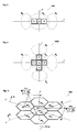
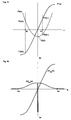
- Fig. 1 shows two flying objects TT1 and TT2 in an antenna beam B, of which the first above and the second below the boresight axis bx.
- E. Brookner, op. Cit., Chapter 5, pages 323 - 330 the spatial position of a Flying object can no longer be determined precisely as soon as a second flying object is in the same Radar steel is located.
- the phase of the resulting difference signal changes compared to the single-target case regarding the sum signal.
- conventional monopulse radars deliver faulty ones Angle measurement data, provided that the targets cannot be separated by distance.
- a special case of the two-target case is the reflection of the radar echo reflected by a flying object e.g. on a water surface.
- an elevation angle error signal usually occurs which is not zero even if the boresight axis is aligned precisely with the flying object.
- a second target echo signal reflected on the water surface is received.
- the resulting signal can then neither be resolved in distance nor in angle with respect to these two signals.
- the superimposition of these two echo signals therefore gives incorrect information regarding the elevation of the target object.
- the elevation servo circuit guides the boresight axis in the wrong direction away from the target during the tracking phase.
- Radar device is an amplitude monopulse radar device, in which the conventional with four Antennae provided with feeds (see E. Brookner, op. Cit., Chapter 5, page 301, Fig. 5.1-3) is rotated by 45 ° (diamond arrangement of the antenna horns). In addition to the previously known Antenna signals (see E. Brookner, op. Cit., Chapter 5, page 301, Fig.
- cross signal Cross difference or Cross term signal
- An antenna can also be used for this method, the three antenna horns forming a triangle having.
- the crossfeed method is therefore based, among other things, on on the evaluation of a cross term signal, which is generated by difference formation of signals emitted by antenna horns, which are not all in the measurement plane and in the basic version of the crossfeed antenna Form a cross.
- the present invention is therefore based on the object of a method and a radar device to be indicated by the two flying objects regardless of their position within the radar beam can be precisely located and measured in terms of their location.
- the second signal can instead of a second flying object also a reflected signal from the first flying object.
- the method according to the invention allows the echo signals from two to be in the antenna beam flying objects resolved and for determining the position of the flying objects in azimuth and elevation be used.
- the method according to the invention is suitable as an extension for both Amplitude as for phase monopulse radar devices, as search, target tracking or secondary radar devices be used.
- Dependent on the position of the flying objects within the antenna beam This avoids measurement errors.
- the arrangement and configuration provided according to the invention the antenna antenna or partial antennas and the evaluation of the signals emitted by them can be realized with relatively little effort.
- the area of unfavorable phase positions close to 0 ° or 180 ° between a directly received and the corresponding one indirectly reflected echo signal or the signal from a second target, making the measurement unfavorable influence, is greatly reduced by the inventive method and the device. It is particularly important for search and secondary radar systems that this also applies measurement errors are completely avoided with target deposits perpendicular to the measuring axis.
- the present invention is based on the finding that at least three sub-antennas A, B and ⁇ , the signals of which are combined with one another in such a way that two of them are required to determine the placement angle of two flying objects in one dimension (measuring axis), which are simultaneously detected by the monopulse antenna linearly independent functions F1 (x), F2 (x) (x is the target position in the selected measurement dimension, e.g. azimuth), which are not influenced by lateral positions of the detected flying objects perpendicular to the measurement axis x.
- the resulting functions F1 (x) and F2 (x) (and thus the partial antennas formed, for example, by combinations of antenna elements and the combination rule for their signals) must meet certain conditions described below.
- the intended measuring axes x, y correspond to azimuth and elevation and can be perpendicular to each other. It is e.g. however, it is also possible that the intended Measuring axes x, y enclose an acute angle and neither with azimuth nor with elevation agree in terms of direction. The direction perpendicular to the first measuring axis x therefore does not have to be inevitably correspond to the direction of the second measuring axis y. In the given embodiments, unless specifically stated, the measuring axes x and y are perpendicular to each other and chosen in accordance with azimuth or elevation. The dimensions perpendicular to the measurement dimensions x and y are referred to as sx and sy below.
- the radiation diagrams have the same amplitude and phase response perpendicular to the measuring plane and the axes bx A , bx B and bx ⁇ of the sub-antennas A, B and ⁇ consequently lie in this measuring plane .
- the partial antennas A, B and ⁇ which receive beams within the measuring plane in different directions (squint beams that only have an angular difference within the measuring plane) and which have a common phase center or an identical phase response.
- the phase centers of the partial antennas A, B and ⁇ or the corresponding subarrays, the antenna beams of which are preferably transmitted in parallel, should lie on a straight line.
- the partial beams should have the same direction and directional characteristic in planes perpendicular to the measuring plane.
- the requirement for phase monopulse radar devices can be met particularly easily.
- the formation of a cross-term signal (cross difference) with signal components from antenna horns with assigned radiation directions that are not in the measurement plane can therefore be dispensed with.
- Lateral shelves (perpendicular to the measurement plane) of the flying objects TT1, TT2 therefore do not influence the measurement results obtained in relation to the measurement plane.
- the measurement is no longer impossible if one of the flying objects has the same storage in the measurement axis and perpendicular to it.
- the functions F1 (x) and F2 (x) are selected such that they are linearly independent of one another and, in the case of a single target, give signals ( F1 ACT and F2 ACT ) which are purely real or purely imaginary. Second, equations containing the in-phase and quadrature components of the two signals F1 ACT and F2 ACT , which are complex in the two-target case, and the functions F1 (x) and F2 (x) themselves, are solved with respect to the four unknowns contained therein.
- the functions for the second measuring axis y are marked accordingly ( F1 (y), F2 (y), etc.).
- the two independent functions F1 (x) and F2 (x) required to determine the position of the flying objects per measurement dimension are formed as follows:
- the signals a2 (x, sx), b2 (x, sx) and ⁇ 2 (x, sx) emitted by partial antennas A, B and ⁇ of an extended monopulse antenna are generally of the position x of a flying object with respect to the measurement dimension and the position perpendicular thereto sx dependent.
- the radiation diagrams of the partial antennas A, B and ⁇ have the same amplitude and phase response perpendicular to the measurement plane.
- the antenna function ⁇ 2 (x, sx) was used arbitrarily for standardization. This partial antenna function ⁇ 2 (x, sx) and ⁇ (x) is therefore referred to as the reference function and the partial antenna ⁇ as the reference antenna.
- a normalization of the partial antenna functions a (x) and b (x) with ⁇ (x) results in quotients A (x) and B (x), which are independent of deposits in the dimension sx:
- a (x) a (x) / ⁇ (x)
- B (x) b (x) / ⁇ (x)
- phase positions of the partial antenna functions a (x) and b (x) are related to the phase position of the reference function ⁇ (x):
- a (x), ⁇ a (x) and ⁇ b (x) and the phases ⁇ (x), ⁇ a (x) as well as ⁇ b (x) or ⁇ (x) and ⁇ (x) depend on the target position in the measuring axis x.
- Equation sets G12 and G22 result in functions with poles that are unfavorable for further processing. Equation theorem G11 and equation theorem G21 are therefore of practical importance. Either set of equations G11 or set of equations G21 must therefore be fulfilled for each of the functions F1 (x) and F2 (x).
- the weighting factors R, S, T, E, G and H can be freely selected for the functions F1 (x) and F2 (x) in the following formula, in which the affiliation to the amplitude monopulse method is indicated by the index A.
- Mp A ( x ) R * ⁇ a ( x ) ⁇ ⁇ ( x ) + S + T * ⁇ b ( x ) ⁇ ⁇ ( x ) E * ⁇ a ( x ) ⁇ ⁇ ( x ) + G + H * ⁇ b ( x ) ⁇ ⁇ ( x )
- F2 A ( x ) R * ( ⁇ a ( x ) ⁇ ⁇ ( x ) + ⁇ a (- x ) ⁇ ⁇ (- x ) - 2 * ⁇ a (0) ⁇ (0) ) E * ( ⁇ a ( x ) ⁇ ⁇ ( x ) + ⁇ a (- x ) ⁇ ⁇ (- x ) ) + G
- the functions F1 (x) and F2 (x), on the other hand, are always independent of one another if one (eg F1 (x)) is odd and the other ( F2 (x)) is even. Since of the two functions F1 A (x) and F2 A (x) specified for the amplitude monopulse method, for example, the first is odd and the second is even, in addition to claims 1 and 2, requirement 3 mentioned above for independence of functions F1 A (x) and F2 A (x) fulfilled. Since the functions F1 A (x) and F2 A (x) have the same denominator, requirement 4 is also fulfilled.
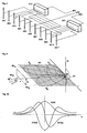
- FIG. 7 shows an extended phase monopulse antenna PA1, which can be used particularly advantageously for the method according to the invention, since antenna elements AE of the phased array antenna PA can be selected without difficulty in such a way that partial antennas ⁇ , C, D are formed, the Phase centers lie on a straight line and their main radiation axes tax C , tax D and tax ⁇ , as shown in FIG. 8, lie parallel to one another in one plane.
- the zones Z ⁇ , Z C , and Z D whose phase centers are to be arranged according to the invention, are selected, for example, as in FIG. 7.
- the antenna PA1 is used, for example, to measure objects in elevation.
- additional partial antennas A, B or zones Z A , Z B are to be provided, the phase centers of which lie on a further straight line, which is arranged, for example, orthogonally to the first straight line on which the phase centers of the partial antennas ⁇ , C, D lie.
- the phase centers of the partial antennas A and B should also have the same distance from the phase center of the central antenna ⁇ .
- those of partial antennas have one Phase monopulse radar device received signals from outside the boresight axis flying object TT were reflected, unequal phases and same amplitudes.
- the difference signals are related on the sum signals a phase difference of 0 ° for amplitude monopulse or 90 ° for Phase monopulse. This fact is also in the formation of the formulas for eleven Monopulse radars to be considered accordingly.
- ⁇ a (x) ⁇ a (-x)
- ⁇ b (x) ⁇ b (-x)
- ⁇ (x) ⁇ (-x)
- ⁇ (x) - ⁇ (x).
- This condition is met if the partial antenna ⁇ and thus its phase center is exactly in the middle between the phase centers the partial antennas A and B is arranged.
- These conditions can be compared to Amplitude monopulse method, in which all sub-antennas A, B and ⁇ the same phase center should have, are relatively easy to meet.
- weighting factors E, G, H, R, S and T in the formulas 8a to 8d either G11 or G21 is satisfied.
- the index ⁇ is used.
- the odd function F1 ⁇ (x) and the even function F2 ⁇ (x) are linearly independent of each other.
- the antenna function pair formed (F1 A (x), F2 A (x) or F1 ⁇ (x), F2 ⁇ (x)), which meets the requirements 1, 2, 3 and 4, is measured for the single-target case.
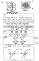
- the determined functional areas are stored in a memory. Function curves measured for, for example, fixed antenna functions F1 (x), F2 (x) are shown in FIG. 10.
- the values of the antenna functions F1 (x), F2 (x) at the locations x1 and x2 where the flying objects TT1, TT2 are located are also shown.
- R1, S1 and T1 denote the coefficients R, S and T selected for the first function F1 (x).
- a target from direction x generates the field strength ex.
- the signal values F1 ACT and F2 ACT determined in the radar device according to these formulas become complex and no longer correspond to the values recorded for the single-target case.
- quadrature signal components F1q ACT and F2q ACT also occur, which must be taken into account for the correct position determination of the two flying objects. The resulting signals are derived below:
- the signals with the field strengths ex1 and ex2 are received from two destinations from the directions x1 and x2, which are phase-shifted by the angle ⁇ and have different signal strengths by the factor ⁇ .
- F1 (x) and F2 (x) are now broken down into their real and imaginary components (p and q):
- F1 (x1) F1p (x1) + j * F1q (x1)
- F1 (x2) F1p (x2) + j * F1q (x2)
- F2 (x1) F2p (x1) + j * F2q (x1)
- F2 (x2) F2p (x2) + j * F2q (x2)
- F 12 (x1, x2, ⁇ , ⁇ ) and F22 (x1, x2, ⁇ , ⁇ ) therefore applies:
- F 1 2 ( x 1, x 2, ⁇ , ⁇ ) ( F 1 p ( x 1) + j * F 1 q ( x 1)) + N * e j ⁇ * ( F 1 p ( x 2) + j * F 1 q ( x 2)) 1 + N * e j ⁇
- F 22 ( x 1, x 2, ⁇ , ⁇ ) ( F 2 p ( x 1) + j * F 2 q ( x 1)) + N * e j ⁇ * ( F 2 p ( x 2) + j * F 2 q ( x 2)) 1 + N * e j ⁇
- the real and imaginary parts correspond to F12p (x1, x2, ⁇ , ⁇ ), F12q (x1, x2, ⁇ , ⁇ ), F22p ( x1, x2, ⁇ , ⁇ ) and F12q (x1, x2, ⁇ , ⁇ ) now the actually measured (or formed in quadrature channels) signal values F1p ACT , F2p ACT , F1q ACT and F2q ACT , which are obtained from the sub-antennas A , B, ⁇ are emitted and correspondingly weighted and combined signals are formed.
- the signal values F1p ACT , F2p ACT , F1q ACT and F2q ACT are therefore equal to the real and imaginary parts F12p (x1, x2, ⁇ , ⁇ ), F12q (x1, x2, ⁇ , ⁇ ), F22p (x1, x2, ⁇ , ⁇ ) and F22q (x1, x2, ⁇ , ⁇ ) of the functions F12 (x1, x2, ⁇ , ⁇ ) and F22 (x1, x2, ⁇ , ⁇ ).
- F 1 p ACT F 1 ( x 1) + N * cos ⁇ * ( F 1 ( x 1) + F 1 ( x 2)) + N 2 * F 1 ( x 2) 1 + 2 * N * cos ⁇ + N 2
- F 1 q ACT ( F 1 ( x 2) - F 1 ( x 1)) * N * sin ⁇ 1 + 2 * N * cos ⁇ + N 2
- F 1 p ACT j * ( F 1 ( x 2) - F 1 ( x 1)) * N * sin ⁇ 1 + 2 * N * cos ⁇ + N 2
- F 1 q ACT - j * F 1 ( x 1) + N * cos ⁇ * ( F 1 ( x 1) + F 1 ( x 2)) + N 2 * F 1 ( x 2) 1 + 2 * N * cos ⁇ + N 2
- F 2 p ACT F 2 ( x 1) + N * cos ⁇ * ( F 2 ( x 1) + F 2 ( x 2)) + N 2 * F 2 ( x 2) 1 + 2 * N * cos ⁇ + N 2
- F 2 q ACT ( F 2 ( x 1) - F 2 ( x 2)) * N * sin ⁇ 1 + 2 * N * cos ⁇ + N 2
- the values F1 A p ACT , F1 A q ACT , F2 A p ACT and F2 A q ACT or F1 ⁇ p ACT , F1 ⁇ q ACT , F2 ⁇ p ACT and F2 ⁇ q ACT are measured.
- the value of x for the target closer to the boresight axis can also be determined approximately from the formulas 120p or 120q derived from the formulas 119a, 119b, in that the value for F2 A (x) or F2 ⁇ (x) is equal to F2 A (0 ) or equal to F2 ⁇ (0).
- the method according to the invention therefore allows, in comparison to the classic monopulse method Even in the case of a single target, the exact determination of the target data, since x, y each for determining the target deposits two equations are available.
- Fig. 4 shows a section through a parabolic antenna
- the same procedure can also be carried out for the second measuring axis (elevation).
- the centrally located partial antenna ⁇ can serve as a reference antenna for both measurement dimensions.
- the main beam direction of the partial antenna ⁇ lies together with the main beam directions of the partial antennas A and B in a first measuring plane and together with the axes of the partial antennas C and D in a second measurement plane, which is preferably orthogonal to the eleventh plane.
- partial antennas consisting of antenna elements AE1,..., AEn can also be used advantageously for the amplitude monopulse method.
- the antenna elements AE1, ..., AEn are to be arranged and connected to existing networks AFa and AFb in such a way that the main radiation directions of the partial antennas are in turn aligned as shown in FIG. 6.
- the signal a (x) is emitted by the network AFa, the signal b (x) by the network AFb and the signal ⁇ (x) by the antenna element AE6.
- the weighting and combination of the antenna signals a (x), b (x) and ⁇ (x) takes place, for example, in a subsequent network.
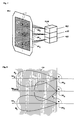
- FIG. 9 shows a monopulse radar device which has either an antenna HA2 or an antenna PA, one for summing and difference formation and for weighting the antenna signals a (x), b (x), ⁇ (x), c (x) and d ( x)
- the network AF provided, a division stage NM provided for forming the quotient, which normally also contains the receiving channels, a quadrature demodulator QG provided for forming quadrature components and a processor PROC connected to a memory unit MEM.
- Networks AF and demodulator QG are known, for example, from E. Brookner, loc. Cit., Chapter 5.4.5, page 316 (Comparators) and Chapter 5.6.2, page 322.
- the quotients according to formulas 16 and 17, which are independent of the incoming signal strength, can be formed in division level NM.
- the processes running in the stages AF, NM, QG can also be carried out in the processor PROC.
- the signals emitted by the partial antennas A, B, ⁇ , C, D are amplified, demodulated and digitized and fed to the processor PROC.
- the processor PROC preferably works according to the pipeline method and therefore has a high read cycle. However, reading out the data may be delayed by a few clock cycles.
- the stored functions F1, F2 are preferably approximated in a first step by third degree polynomials and the equations are solved analytically. The solutions found in this way are preferably used as first approximate values for an iterative process.
- the radar device can be designed as an expanded amplitude or as a phase monopulse radar device and is accordingly equipped with one of the antennas shown in FIG. 2, 3, 5 or 7 (for example, home antenna HA2 or phased array antenna PA). Mistake.
- the signals a (x), b (x) and ⁇ (x) (or c (y), d (y) and ⁇ (y) emitted by the partial antennas A, B, ⁇ , C, D are ) individually weighted and added for numerators and denominators of formulas 16 and 17 (or 101a, 101b).
- the signals are divided according to the formulas 16 and 17 (or 101a, 101b), so that at the output of this stage the signals F12 and F22 correspond to signals which are present in the demodulator QG in in-phase components F1p ACT , F2p ACT and divided into quadrature fractions F1q ACT , F2q ACT .
- the signals F1p ACT , F1q ACT , F2p ACT and F2q ACT determined by these measures in the radar device are sampled according to the signal bandwidth and fed to the processor PROC, which according to formula 119a and 119b uses the ones stored in the memory MEM for the single-target case measured antenna functions F1 (x), F2 (x) determines the solutions x1 and x2 of equations 119a and 119b.
- suitable functions F1 (x), F2 (x) can be defined and the corresponding antenna beams can then be determined according to Formula 1000.
- array antennas in which signal components are to be obtained from all antenna elements if possible, it makes more sense to define and optimize lighting functions Js , J01 and J02 and to use these to determine functions F1 (x) and F2 (x).
- the transition from the lighting function Js ; J01 or J02 which determines the weighting of the elementary signals of an array antenna as a function of the location lx on the array, for the corresponding antenna functions Fs (x), F01 (x) and F02 (x) is carried out by the founer transformation.
- Illumination functions Js (lx), J01 (lx) and J02 (lx) are used to scan or measure the wave fronts arriving from the measured targets, which are curved in the case of a multi-target case. If only a spherical or approximately flat wavefront originating from a target were to be measured, its inclination with respect to the radar antenna could be determined using an illumination function in accordance with the classic monopulse method (inclination monopulse). To measure the curvature of a wavefront originating from two targets, an additional lighting function is required which is linearly independent of the first. The extension of the classic monopulse method by introducing an additional antenna function is referred to below as the curvature monopulse method.
- the lighting function J02 (lx) is optimized for a measurement of the field curvature.
- antenna functions F1 (x), F2 (x) are achieved, by means of which the resolution of two targets with regard to position, signal power and signal phase is achieved. After determining the antenna functions F1 (x), F2 (x), the method according to the invention is carried out as already described above.
- the first odd and the second is preferably chosen.
- the course of the odd lighting function is point-symmetrical with respect to the origin of the coordinate system.
- the course of the straight lighting function is axisymmetric with respect to the ordinate of the coordinate system.
- the illumination function Js (lx) which changes into the sum or reference function Fs (x) by applying the Fourier transformation, is to be selected such that the ratio F01 (x) / Fs (x) or F02 (x) / Fs (x ) remains constant for shelves perpendicular to the measuring axis. This can be achieved, for example, if, in addition to fulfilling the above-mentioned conditions, the lighting functions J01s (lsx), J02s (lsx) and Jss (lsx) have functional profiles over the aperture of the array antenna perpendicular to the measuring axis, which differ only in a proportionality factor.
- the antenna functions resulting from the two-dimensional lighting functions j01 (lx, lsx), j02 (lx, lsx) js (lx, lsx) by Fourier transformation are f01 (lx, lsx), f02 (lx, lsx) fs (lx, lsx) .
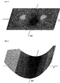
- FIG. 11 shows the two-dimensional pattern of the antenna function of the cross term signal (diagonal difference signal) known from Sherman, SM, Monopulse Principles and Techniques, Artech House, Norwood, MA, 1984, page 341, FIG. 12.2-1.
- the cross term signal (diagonal difference signal) known from Sherman, SM, Monopulse Principles and Techniques, Artech House, Norwood, MA, 1984, page 341, FIG. 12.2-1.
- the values of this cross term function change as a function of target positions x in the measurement plane and as a function of target positions sx perpendicular to the measurement plane.
- the cross term function known from the prior art therefore does not meet requirement 3 'according to the invention.
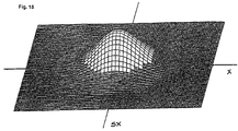
- FIG. 13 shows the two-dimensional pattern of an illumination function defined according to the invention for a function which can be used according to the invention (for example for FIG. 10, function F2 (x)).
- lx is the location on the antenna measured from the center and lxo is the distance from the edge to the center of the antenna.
- the function W2 is ideal for measuring the curvature of a field. However, it has strong side lobes that are intolerable. The lighting function J02 should therefore be approximated to the function W2 until the side peaks reach the still tolerable dimension. It is now: the reference power of the curvature beam and the measurement performance.
- lx0 is the location on the aperture where the excitation amplitude of the Gaussian function has decreased by 1 / e 1 ⁇ 2 or the excitation power by 1 / e compared to the value in the center.
- the method according to the invention can be used particularly advantageously in connection with radar devices which are suitable for carrying out the sidelobe suppression (SLS) method, which is described, for example, in Richard C. Johnson, Antenna Engineering Handbook, Mc Graw-Hill Book Company, New York 1993, third Edition, chapter 33, pages 33-6 to 33-8.
- SLS sidelobe suppression
- a gap pattern (Notch-Pattem) is used, which results from the sum pattern by the phase inversion of the elementary signals from antenna elements, which is in the middle of the Form a column antenna perpendicular to the measuring axis.
- This gap pattern is similar to the pattern of the lighting function J02 (lx) defined according to the invention shown in FIG. 13.
- the illumination function of the SLS array antenna corresponding to the gap pattern corresponds, after Fourier transformation and normalization with the sum function, to a straight function F2 (x) which can be used according to the invention.
- a radar system which is suitable for carrying out the sidelobe suppression (SLS) method can therefore be expanded to a system suitable for carrying out the method according to the invention with practically no manual changes to the antenna.
- the two methods provided in a radar system for suppressing target signals which are received via side lobes and for resolving two targets which are detected by the main lobes therefore complement one another in an ideal manner.
- the target directions determined according to the method according to the invention can also be used for control purposes the antenna can be used.
- the transmission diagram is set so that with respect to the direction of a Interference signal or a target to be hidden, if possible, no signal transmitted or received becomes.
- the data available in the processor for determining the target positions x1, x2 can also be used for determining the phase angle den between the signals arriving from direction x1, y1 and x2, y2.
- the angle ⁇ can be clearly determined on the basis of the values of sin ⁇ and cos ⁇ . Likewise can the angle ⁇ also with the data of the curvature channel (replace F1 in the formulas above with F2) as well as the data used in the phase monopulse method. By measurement of the angle ⁇ can distinguish real two-target cases from reflection cases as well as unfavorable phase positions are recognized, in which the angle ⁇ becomes close to zero or close to ⁇ .
- Phase differences ⁇ close to zero or close to ⁇ can e.g. by changing the transmission frequency be avoided.
- the phase changes between two measurements are typical about a hundred times smaller than in two-target cases where the transponder have different transmission frequencies from two destinations. This allows reflections from real A distinction is made between two target cases.
- Two targets can also have a difference frequency (Beat) can be assigned, which allows this target pair to be restored at a later time to identify.
- Beat difference frequency
- the power ratios L A 1, L A 2 can also be determined using the data of the curvature channel and the data used in the phase monopulse method. Based on the data obtained, the goals can be marked and then more easily followed. If two targets are detected by the radar system according to the invention (see FIG. 9), their angle data x1, y1 and x2, y2 can be determined according to the invention. If the targets swap their positions at a later moment, for example, this is not recognized if only the angle data x1, y1 and x2, y2 are determined. If, however, the power ratios L A 1, L A 2 were determined before the swapping, the targets can be clearly identified again even after a transmission interruption.
- the effective antenna-independent target-specific services are determined the directional characteristic of the sum diagram in the direction of the target in question with the calibration direction as a correction factor.
- the determination of the performance ratios L A 1, L A 2 and the target-specific benefits can be used extremely advantageously for various purposes.
- the goals can be labeled as described above, making it much easier to pursue these goals.
- the reflection factor can also be determined for mirrored targets. It can also be determined whether there is a one-target or a two-target case. If the division of the performance ratios L A 1, L A 2 goes towards zero or ⁇ , there is a single-target case. If a threshold value close to zero or ⁇ is undershot or exceeded, the procedure for determining the target data according to the formulas (Formula 121) is therefore used for the single-target case.
- the determination of the power ratios L A 1, L A 2 is also advantageous when measuring the target in two dimensions.
- target deposits x1, x2, y1 and y2 can be determined by the method according to the invention. It is initially unclear which target shelves are to be combined. Is the first target at x1, y2 and the second target at x2, y1 or is the first target at x1, y1 and the second target at x2, y2?
- the performance measurement can now be used to determine which pair of target shelves x1, y1; x1, y2 or x2, y1; x2, y2 has at least approximately the same power ratios L A 1 and L A 2 and belongs to a target pair and not to a phantom pair. Of particular importance is the determination of the performance ratios L A 1, L A 2 for the suppression or separation of interference signals (defruiting, degarbeling). The underlying individual signals can thus be identified.
- the honeycomb antenna provided with seven subarrays shown in FIG. 17 can also be used advantageously WA, which is able to measure two targets in three coplanar dimensions x, y, z and based on the measured values x1, x2, y1, y2, z1, z2.
- the three measuring axes x, y, z run through the phase centers pz5, pz ⁇ , pz6; pz3, pz ⁇ , pz4 or pz1, pz ⁇ , pz2 of three subarrays each and preferably intersect in the phase center pz ⁇ of the central subarray ⁇ .
- Phantom- or ghost images can be complete by using the measurements from the third measurement dimension be switched off without taking into account the performance of the individual signals are. This gives the advantage that clear location is also possible if the performance ratio both target echo signals are the same.
- the destinations TT1, TT2 shown in FIG. 17 are present Places that are identified by measurement values from all three measurement dimensions.
- the target data can be measured using the method according to the invention only with respect to position x1, y1; x2, y2, only with respect to phase ⁇ or only with regard to the power ratios L A 1, L A 2, but also in any combination.
Landscapes
- Engineering & Computer Science (AREA)
- Radar, Positioning & Navigation (AREA)
- Remote Sensing (AREA)
- Computer Networks & Wireless Communication (AREA)
- Physics & Mathematics (AREA)
- General Physics & Mathematics (AREA)
- Radar Systems Or Details Thereof (AREA)
- Variable-Direction Aerials And Aerial Arrays (AREA)
Abstract
Description
Die vorliegende Erfindung betrifft ein Verfahren zur Ortung von Flugobjekten für ein Amplituden- oder Phasen-Monopulsradargerät nach Anspruch 1 bzw. 2 sowie ein entsprechendes Amplituden- oder Phasen-Monopulsradargerät nach Anspruch 18 bzw. 19.The present invention relates to a method for locating flying objects for an amplitude or phase monopulse radar device according to claim 1 or 2 and a corresponding amplitude or phase monopulse radar device according to claim 18 or 19.
Zur Ortung und gegebenenfalls Verfolgung von Flugobjekten werden heute normalerweise Monopulsradargeräte eingesetzt, wie sie u.a. in M. Skolnik, Radar-Handbook, Mc Graw Hill 1970, Kapitel 21 oder E. Brookner (editor), ASPECTS OF MODERN RADAR, Artech House Inc. 1988, Kapitel 5 (S.M. Sherman, Monopulse Principles and Techniques) beschrieben sind. Mit Monopulsradargeräten werden mit jedem empfangenen Puls in Azimut und Elevation Winkelfehlersignale erzeugt, die zu Null werden, wenn die Antennen- bzw. Boresightachse genau auf das Ziel ausgerichtet ist. Die Ausrichtung und gegebenenfalls Nachführung der Boresightachse erfolgt mechanisch oder mit einer Phased-Array-Antenne elektronisch. Oft wird mit einer Phased-Array-Antenne der Messbereich in Elevation elektronisch und in Azimut mechanisch abgetastet (A.E. Acker, HOW TO SPEAK RADAR, BASIC FUNDAMENTALS AND APPLICATIONS OF RADAR, Varian Associates, Palo Alto 1988, Seiten 30 und 31).Monopulse radar devices are normally used today for locating and possibly tracking flying objects used, such as in M. Skolnik, Radar Handbook, Mc Graw Hill 1970, chapter 21 or E. Brookner (editor), ASPECTS OF MODERN RADAR, Artech House Inc. 1988, Chapter 5 (S.M. Sherman, Monopulse Principles and Techniques). With monopulse radars Angle error signals are generated with each received pulse in azimuth and elevation become zero if the antenna or boresight axis is precisely aligned with the target. The Alignment and, if necessary, tracking of the boresight axis takes place mechanically or with a Phased array antenna electronic. The measuring range is often measured with a phased array antenna Elevation electronically and mechanically scanned in azimuth (A.E. Acker, HOW TO SPEAK RADAR, BASIC FUNDAMENTALS AND APPLICATIONS OF RADAR, Varian Associates, Palo Alto 1988, pages 30 and 31).
Bekannte Amplituden- oder Phasen-Monopulsradargeräte liefern genaue Winkel-Messdaten bezüglich einem Flugobjekt, solange zusätzlich zu den direkt vom überwachten Flugobjekt empfangenen Signalen, keine Signale von weiteren Objekten oder ein- oder mehrfach reflektierte Signale vom ersten oder den weiteren Objekten empfangen werden.Known amplitude or phase monopulse radars provide accurate angle measurement data with respect a flying object, in addition to those received directly from the monitored flying object Signals, no signals from other objects or single or multiple reflected signals from first or the other objects are received.
Fig. 1 zeigt zwei Flugobjekte TT1 und TT2 in einem Antennenstrahl B, von denen sich das erste über und das zweite unterhalb der Boresightachse bx befindet. Gemäss E. Brookner, a.a.O., Kapitel 5, Seiten 323 - 330 kann mit einem konventionellen Monopulsradargerät die räumliche Lage eines Flugobjekts nicht mehr präzise bestimmt werden, sobald sich ein zweites Flugobjekt in demselben Radarstahl befindet. Im Vergleich zum Einziel-Fall ändert sich die Phase des resultierenden Differenzsignals bezüglich dem Summensignal. Zudem liefern konventionelle Monopulsradargeräte fehlerhafte Winkel-Messdaten, sofern die Ziele auch distanzmässig nicht getrennt werden können. Ein Spezialfall des Zweiziel-Falles ist die Spiegelung des von einem Flugobjekt reflektierten Radarechos z.B. auf einer Wasseroberfläche.Fig. 1 shows two flying objects TT1 and TT2 in an antenna beam B, of which the first above and the second below the boresight axis bx. According to E. Brookner, op. Cit., Chapter 5, pages 323 - 330, the spatial position of a Flying object can no longer be determined precisely as soon as a second flying object is in the same Radar steel is located. The phase of the resulting difference signal changes compared to the single-target case regarding the sum signal. In addition, conventional monopulse radars deliver faulty ones Angle measurement data, provided that the targets cannot be separated by distance. On A special case of the two-target case is the reflection of the radar echo reflected by a flying object e.g. on a water surface.
Wird z.B. mit einem Zielfolge-Radargerät ein über Wasser fliegendes Objekt verfolgt, tritt meist ein Elevations-Winkelfehlersignal auf, das auch dann nicht null ist, wenn die Boresightachse genau auf das Flugobjekt ausgerichtet ist. Neben dem Echosignal des überwachten Flugobjekts wird ein zweites an der Wasseroberfläche gespiegeltes Zielechosignal empfangen. Das resultierende Signal kann dann bezüglich diesen beiden Signalen weder in der Distanz noch im Winkel aufgelöst werden. Die Überlagerung dieser zwei Echosignale ergibt daher falsche Angaben bezüglich der Elevation des Zielobjekts. Dadurch führt der Elevations-Servokreis während der Nachführphase die Boresightachse in eine falsche vom Ziel abgelegene Richtung. Bekannt ist femer, dass zur gleichzeitigen Vermessung von nt verschiedenen kohärenten Zielen in 2 Dimensionen theoretisch wenigstens ma = 2 * nt verschiedene Teilantennen (unabhängige Empfangspunkte innerhalb eines Antennensystems) benötigt werden, die komplexe Signale abgeben, welche in exakt kalibrierten, stabilen Inphase- und Quadraturkanälen zu verarbeiten sind. Zur Ermittlung der Zieldaten werden m, komplexe Gleichungen benötigt, die vom Computer des Radarsystems nach den Unbekannten aufzulösen sind (siehe A.I. Leonov, K.I. Fomichev, Monopulse Radar, 1986 Artech House Inc., Kapitel 5.4.4 (Functional Signal Processing)). Diese theoretischen Überlegungen wurden aufgrund der zu erwartenden Schwierigkeiten bisher noch nicht in der vorgeschlagenen Form in die Praxis umgesetzt (vgl. E. Brookner, a.a.O., Kapitel 5.7, Seiten 323 und 324). Sie liegen der nachfolgend erwähnten Lösung zugrunde, bei der es gelang, durch gezielte Vereinfachungen ein Verfahren zur Vermessung von zwei gleichzeitig auftretenden Zielen zu finden, dass aufgrund der vorgenommenen Einschränkungen jedoch nur für Zielfolge-Radargeräte anwendbar ist.If, for example, an object flying above water is tracked with a target following radar device, an elevation angle error signal usually occurs which is not zero even if the boresight axis is aligned precisely with the flying object. In addition to the echo signal of the monitored flying object, a second target echo signal reflected on the water surface is received. The resulting signal can then neither be resolved in distance nor in angle with respect to these two signals. The superimposition of these two echo signals therefore gives incorrect information regarding the elevation of the target object. As a result, the elevation servo circuit guides the boresight axis in the wrong direction away from the target during the tracking phase. It is also known that, for the simultaneous measurement of n t different coherent targets in two dimensions, theoretically at least m a = 2 * n t different sub-antennas (independent reception points within an antenna system) are required, which emit complex signals which are in exactly calibrated, stable in-phase - and quadrature channels are to be processed. To determine the target data, complex complex equations are required, which must be solved by the computer of the radar system according to the unknowns (see AI Leonov, KI Fomichev, Monopulse Radar, 1986 Artech House Inc., chapter 5.4.4 (Functional Signal Processing)). Due to the expected difficulties, these theoretical considerations have not yet been put into practice in the proposed form (cf. E. Brookner, loc. Cit., Chapter 5.7, pages 323 and 324). They are the basis of the solution mentioned below, in which it was possible to find a method for measuring two simultaneously occurring targets by means of targeted simplifications, but because of the restrictions made it can only be used for target radar devices.
Durch dieses aus Dr. A. Schenkel, Crossfeed monopulse - a specific method to eliminate mistrakking over sea, presented at the international conference "Radar-87", London, 19-21 Oktober 1987 bekannte Verfahren werden fehlerhafte Vermessungen von über Wasser fliegenden Objekten vermieden. Bei dieser Methode, die ferner in den Patentschriften U.S. 4,084,160 und U.S. 4,219,816 bzw. CH 592 887 und CH 629 898 beschrieben ist, werden die bisher benutzten sowie weitere Winkelfehlersignale verwendet, die bei richtiger Kombination auch im Spiegelungsfall eine Signal-Nullstelle auf der Boresightachse erzeugen. Die Anwendung dieser Methode bei der Vermessung eines Flugobjekts in Azimut und Elevation erlaubt zudem eine Vermessung nicht nur beim beschriebenen Spiegelungsfall (Ziel 1 und 2 haben denselben Azimut), sondern beim allgemeinen Zweiziel-Fall (Ziel 1 und 2 unterscheiden sich in Azimut und Elevation). Das für diese Methode verwendete Radargerät ist ein Amplituden-Monopulsradargerät, bei dem die konventionelle mit vier Antennenhömem (Feeds) versehene Antenne (vgl. E. Brookner, a.a.O., Kapitel 5, Seite 301, Fig. 5.1-3) um 45° gedreht ist (Diamantanordnung der Antennenhörner). Nebst den bisher bekannten Antennensignalen (vgl. E. Brookner, a.a.O., Kapitel 5, Seite 301, Fig. 5.1-3 : Sum, Traverse difference, Elevation difference) wird darin neu ein sogenanntes Crossignal (Cross difference bzw. Kreuztermsignal) verwendet, das der Differenz der beiden Summensignale entspricht, die durch Addition der Signale der einander diagonal gegenüberliegenden Antennenhörner gebildet werden. Anwendbar für diese Methode ist ferner eine Antenne, die drei ein Dreieck bildende Antennenhörner aufweist. Die Crossfeed-Methode basiert daher u.a. auf der Auswertung eines Kreuztermsignals, das durch Differenzbildung von Signalen erzeugt wird, die von Antennenhörnem abgegeben werden, die nicht alle in der Messebene liegen und in der Grundausführung der Crossfeed-Antenne ein Kreuz bilden. Through this from Dr. A. Schenkel, Crossfeed monopulse - a specific method to eliminate mistrakking over sea, presented at the international conference "Radar-87", London, October 19-21, 1987 Known methods are incorrect measurements of objects flying over water avoided. This method, further described in U.S. Pat. 4,084,160 and U.S. 4,219,816 or CH 592 887 and CH 629 898, the previously used as well further angle error signals are used, which, if properly combined, also result in a mirroring event Generate signal zero on the boresight axis. The application of this method to the survey of a flying object in azimuth and elevation also allows a measurement not only at the Mirroring case described (Objectives 1 and 2 have the same azimuth), but in the general Two-target case (targets 1 and 2 differ in azimuth and elevation). The one used for this method Radar device is an amplitude monopulse radar device, in which the conventional with four Antennae provided with feeds (see E. Brookner, op. Cit., Chapter 5, page 301, Fig. 5.1-3) is rotated by 45 ° (diamond arrangement of the antenna horns). In addition to the previously known Antenna signals (see E. Brookner, op. Cit., Chapter 5, page 301, Fig. 5.1-3: Sum, Traverse difference, Elevation difference) is now a so-called cross signal (cross difference or Cross term signal) is used, which corresponds to the difference between the two sum signals, which by Addition of the signals of the diagonally opposite antenna horns are formed. An antenna can also be used for this method, the three antenna horns forming a triangle having. The crossfeed method is therefore based, among other things, on on the evaluation of a cross term signal, which is generated by difference formation of signals emitted by antenna horns, which are not all in the measurement plane and in the basic version of the crossfeed antenna Form a cross.
Obwohl das beschriebene (Crossfeed-) Verfahren gegenüber dem konventionellen Monopuls-Verfahren grundlegende Verbesserungen erbrachte, ist unter bestimmten Umständen auch bei diesem Verfahren mit Messfehlern zu rechnen. Falls z.B. ein Flugobjekt in einem Winkel von 45° über der um 45° gedrehten Antenne (Diamantanordnung der Antennenhörner gemäss CH Pat. 592 887, Fig. 2a) erscheint und somit gleiche Ablage in Elevation und Azimut aufweist, wirkt die Antenne in Bezug auf dieses Objekt als konventionelle Monopulsantenne, da das Kreuztermsignal, wie leicht nachgeprüft werden kann, gleich null wird. Bei einer Antennenanordnung mit drei Antennenhömem (A, B, C) gemäss CH Pat. 592 887, Fig. 2c treten zusätzlich Messfehler auf, die stark von der Verschiebung des zu vermessenden Flugobjekts senkrecht zur Messachse und damit senkrecht zur Strecke abhängen, die durch die beiden den Summenanteil des Kreuztermsignals liefernden Hörner (A und C) gebildet wird. Weniger ausgeprägt, aber dennoch spürbar, treten diese Probleme bei der Diamantanordnung der Antennenhömer auf; dabei müssen für eine Messachse statt drei, vier Antennenhörner vorgesehen werden. Bei dieser Anordnungen können Messfehler jedoch nur vermieden werden, wenn die Boresightachse präzise auf das Ziel ausgerichtet wird und die Antennenhörner identische Charakteristiken aufweisen und präzise justiert sind. Dies kann jedoch nur bei Zielfolgeradargeräten mit einem Servokreis und mit einem entsprechend hohen Aufwand erreicht werden. Gemäss E. Brookner, a.a.O., Kapitel 5.1.5, Seite 305 bildet jedoch insbesondere der hohe Aufwand bei der Herstellung und Kalibrierung der Antenne den Hauptnachteil der Monopulstechnik. Die durch den Zweiziel-Fall gestellten zusätzlichen Anforderungen an die Präzision der Antennengeometrie führen zu einem entsprechend hohen Aufwand. Bei nicht optimaler Antennengeometrie werden die oben beschriebenen Probleme insbesondere dann spürbar, wenn die Phasenlage zwischen einem direkt empfangenen und dem reflektierten Echosignal nahe 0° oder 180° ist. Bei einer Anwendung in Such- oder Sekundärradaranlagen wären die resultierenden Fehler in der Zielwinkelbestimmung nicht mehr tolerierbar. Dies wird u.a. in Sherman, S.M., Monopulse Principles and Techniques, Artech House, Norwood, MA, 1984, Seite 340 durch die Feststellung bestätigt, dass das Diagonal-Differenzsignal (bezüglich der Definition dieses Signals, das auch Kreuztermsignal genannt wird, siehe a.a.O. auf Seiten 74 - 75) keinen praktischen Wert für die Bestimmung der Raumwinkel von ein oder zwei Zielen aufweist.Although the described (crossfeed) method compared to the conventional monopulse method provided fundamental improvements is also in this under certain circumstances Procedure to expect measurement errors. If e.g. a flying object at an angle of 45 ° above the Antenna rotated by 45 ° (diamond arrangement of the antenna horns according to CH Pat. 592 887, Fig. 2a) appears and thus has the same storage in elevation and azimuth, the antenna acts in relation on this object as a conventional monopulse antenna, since the cross term signal how easy can be checked, becomes zero. With an antenna arrangement with three antenna heights (A, B, C) according to CH Pat. 592 887, Fig. 2c additional measurement errors occur that are strongly related to the displacement of the flying object to be measured perpendicular to the measuring axis and thus perpendicular to the Depending on the distance, the two horns supplying the sum of the cross term signal (A and C) is formed. Less pronounced, but still noticeable, these problems occur with the Diamond arrangement of antenna antennas; this means that for one measuring axis instead of three or four antenna horns be provided. With this arrangement, measurement errors can only be avoided when the boresight axis is precisely aligned with the target and the antenna horns have identical characteristics and are precisely adjusted. However, this can only be done with target radar devices can be achieved with a servo circuit and with a correspondingly high outlay. According to E. Brookner, loc. Cit., Chapter 5.1.5, page 305, however, the high effort is particularly important the main disadvantage of monopulse technology in the manufacture and calibration of the antenna. By the two-target case made additional demands on the precision of the antenna geometry lead to a correspondingly high effort. If the antenna geometry is not optimal, the Problems described above are particularly noticeable when the phase relationship between one received directly and the reflected echo signal is close to 0 ° or 180 °. In one application in search or secondary radar systems the resulting errors in the target angle determination would be no longer tolerable. This will include in Sherman, S.M., Monopulse Principles and Techniques, Artech House, Norwood, MA, 1984, page 340 confirmed by the finding that the diagonal difference signal (regarding the definition of this signal, which is also called cross term signal, see above. on pages 74 - 75) no practical value for the determination of the solid angle of has one or two goals.
Der vorliegenden Erfindung liegt daher die Aufgabe zugrunde, ein Verfahren und eine Radarvorrichtung anzugeben durch die zwei Flugobjekte unabhängig von ihrer Position innerhalb des Radarstrahls präzise geortet und bezüglich ihrer Lage vermessen werden können. Das zweite Signal kann statt von einem zweiten Flugobjekt auch ein reflektiertes Signal vom ersten Flugobjekt sein.The present invention is therefore based on the object of a method and a radar device to be indicated by the two flying objects regardless of their position within the radar beam can be precisely located and measured in terms of their location. The second signal can instead of a second flying object also a reflected signal from the first flying object.
Diese Aufgabe wird durch die in den Patentansprüchen 1 bzw. 2 sowie 18 bzw. 19 angegebenen Massnahmen gelöst. Vorteilhafte Ausgestaltungen der Erfindung sind in weiteren Ansprüchen angegeben. This object is achieved by those specified in claims 1 and 2 and 18 and 19, respectively Measures solved. Advantageous embodiments of the invention are in further claims specified.
Durch das erfindungsgemässe Verfahren können die Echosignale von zwei sich im Antennenstrahl befindenden Flugobjekten aufgelöst und zur Lagebestimmung der Flugobjekte in Azimut und Elevation verwendet werden. Das erfindungsgemässe Verfahren eignet sich als Erweiterung sowohl für Amplituden- wie für Phasen-Monopulsradargeräte, die als Such-, Zielfolge- oder Sekundärradargeräte eingesetzt werden. Von der Position der Flugobjekte innerhalb des Antennenstrahls abhängige Messfehler werden dadurch vermieden. Die erfindungsgemäss vorgesehene Anordnung und Ausprägung der Antennenhömer oder Teilantennen und die Auswertung der davon abgegebenen Signale kann mit verhältnismässig geringem Aufwand realisiert werden. Der Bereich ungünstiger Phasenlagen nahe 0° oder 180° zwischen einem direkt empfangenen und dem dazu korrespondierenden indirekt reflektierten Echosignal oder dem Signal von einem zweiten Ziel, die die Messung ungünstig beeinflussen, wird durch das erfindungsgemässe Verfahren und die Vorrichtung stark vermindert. Insbesondere für Such- und Sekundärradaranlagen ist von Bedeutung, dass dadurch auch bei Zielablagen senkrecht zur Messachse Messfehler vollständig vermieden werden.The method according to the invention allows the echo signals from two to be in the antenna beam flying objects resolved and for determining the position of the flying objects in azimuth and elevation be used. The method according to the invention is suitable as an extension for both Amplitude as for phase monopulse radar devices, as search, target tracking or secondary radar devices be used. Dependent on the position of the flying objects within the antenna beam This avoids measurement errors. The arrangement and configuration provided according to the invention the antenna antenna or partial antennas and the evaluation of the signals emitted by them can be realized with relatively little effort. The area of unfavorable phase positions close to 0 ° or 180 ° between a directly received and the corresponding one indirectly reflected echo signal or the signal from a second target, making the measurement unfavorable influence, is greatly reduced by the inventive method and the device. It is particularly important for search and secondary radar systems that this also applies measurement errors are completely avoided with target deposits perpendicular to the measuring axis.
Die Erfindung wird nachfolgend anhand von Zeichnungen beispielsweise näher erläutert. Dabei zeigt
- Fig. 1
- zwei durch einen Antennenstrahl erfasste Flugobjekte,
- Fig. 2
- einen Schnitt durch die Strahlen einer Amplituden-Monopulsantenne mit drei Hömem,
- Fig. 3
- einen Schnitt durch die Strahlen einer Amplituden-Monopulsantenne mit fünf Hömem,
- Fig. 4
- die Homantenne gemäss Fig. 3 in Verbindung mit einem Parabolreflektor,
- Fig. 5
- eine Arrayantenne mit drei Teilantennen für das Amplituden-Monopulsverfahren,
- Fig. 6
- die Antennenstrahlen der in Fig. 2 und Fig. 5 gezeigten Antenne,
- Fig. 7
- eine Phased-Array-Antenne, innerhalb der drei Teilantennen gebildet werden,
- Fig. 8
- die Antennenstrahlen einer Phasen-Monopulsantenne, z.B. einer Phased-Array-Antenne gemäss Fig. 7,
- Fig. 9
- ein erfindungsgemässes Monopulsradargerät,
- Fig. 10
- die Diagramme von zwei Funktionen, die durch Kombination der von einer erweiterten Monopuls-Antenne abgegebenen Signale gebildet werden,
- Fig. 11
- das Diagramm der Beleuchtungsfunktion des Kreuztermsignals (Diagonal-Differenzsignal) mit horizontaler Messachse,
- Fig. 12
- das Diagramm der normierten Kreuztermfunktion deren Funktionswerte, wie ersichtlich, bei Zielablagen senkrecht zur Messachse nicht konstant sind,
- Fig. 13
- das Diagramm der Beleuchtungsfunktion J02 der erfindungsgemäss festgelegten Funktion F02 (Messachse horizontal),
- Fig. 14
- das Diagramm der normierten Funktion gemäss Fig. 13, deren Funktionswerte, wie ersichtlich, bei Zielablagen senkrecht zur Messachse konstant sind,
- Fig. 15
- das Diagramm der zur Normierung vorgesehenen Summenfunktion,
- Fig. 16
- das Diagramm der Beleuchtungsfunktionen J01, J02 realisiert mit einer SLS-Antenne,
- Fig. 17
- eine Waben-Antenne mit Messachsen, die nicht senkrecht aufeinander stehen und
- Fig. 18
- den Verlauf von bevorzugten Beleuchtungsfunktionen.
- Fig. 1
- two flying objects detected by an antenna beam,
- Fig. 2
- a section through the beams of an amplitude monopulse antenna with three levels,
- Fig. 3
- a section through the beams of an amplitude monopulse antenna with five levels,
- Fig. 4
- 3 in connection with a parabolic reflector,
- Fig. 5
- an array antenna with three sub-antennas for the amplitude monopulse method,
- Fig. 6
- the antenna beams of the antenna shown in FIGS. 2 and 5,
- Fig. 7
- a phased array antenna, within which three sub-antennas are formed,
- Fig. 8
- the antenna beams of a phase monopulse antenna, for example a phased array antenna according to FIG. 7,
- Fig. 9
- a monopulse radar device according to the invention,
- Fig. 10
- the diagrams of two functions which are formed by combining the signals emitted by an extended monopulse antenna,
- Fig. 11
- the diagram of the lighting function of the cross term signal (diagonal difference signal) with horizontal measuring axis,
- Fig. 12
- the diagram of the standardized cross term function whose function values, as can be seen, are not constant in the case of target deposits perpendicular to the measurement axis,
- Fig. 13
- the diagram of the lighting function J02 of the function F02 (measuring axis horizontal) defined according to the invention,
- Fig. 14
- 13 the diagram of the normalized function according to FIG. 13, the function values of which, as can be seen, are constant with target deposits perpendicular to the measurement axis,
- Fig. 15
- the diagram of the sum function provided for standardization,
- Fig. 16
- the diagram of the lighting functions J01, J02 realized with an SLS antenna,
- Fig. 17
- a honeycomb antenna with measuring axes that are not perpendicular to each other and
- Fig. 18
- the course of preferred lighting functions.
Der vorliegenden Erfindung liegt die Erkenntnis zugrunde, dass zur Bestimmung der Ablagewinkel von zwei gleichzeitig von der Monopuls-Antenne erfassten Flugobjekten in einer Dimension (Messachse) wenigstens drei Teilantennen A, B und Ω benötigt werden, deren Signale derart miteinander kombiniert werden, dass zwei voneinander linear unabhängige Funktionen F1(x), F2(x) (x ist die Zielablage in der gewählten Messdimension, z.B. Azimut) entstehen, die durch seitliche Ablagen der erfassten Flugobjekte senkrecht zur Messachse x nicht beeinflusst werden. Die resultierenden Funktionen F1(x) und F2(x) (und damit die z.B. durch Kombinationen von Antennenelementen gebildeten Teilantennen und die Kombinationsvorschrift für deren Signale) müssen dabei gewisse im folgenden beschriebene Bedingungen erfüllen.The present invention is based on the finding that at least three sub-antennas A, B and Ω, the signals of which are combined with one another in such a way that two of them are required to determine the placement angle of two flying objects in one dimension (measuring axis), which are simultaneously detected by the monopulse antenna linearly independent functions F1 (x), F2 (x) (x is the target position in the selected measurement dimension, e.g. azimuth), which are not influenced by lateral positions of the detected flying objects perpendicular to the measurement axis x. The resulting functions F1 (x) and F2 (x) (and thus the partial antennas formed, for example, by combinations of antenna elements and the combination rule for their signals) must meet certain conditions described below.
Für den Fall, dass das erfindungsgemässe Verfahren in zwei Messdimensionen durchgeführt wird, ist zu beachten, dass vorgesehene Messachsen x, y mit Azimut und Elevation übereinstimmen und senkrecht zueinander stehen können. Es ist z.B. jedoch auch möglich, dass die vorgesehenen Messachsen x, y einen spitzen Winkel einschliessen und weder mit Azimut, noch mit Elevation richtungsmässig übereinstimmen. Die Richtung senkrecht zur ersten Messachse x muss daher nicht zwangsläufig der Richtung der zweiten Messachse y entsprechen. In den angegebenen Ausführungsbeispielen, sofern nicht ausdrücklich angegeben, sind die Messachsen x und y senkrecht zueinander und übereinstimmend mit Azimut bzw. Elevation gewählt. Die Dimensionen senkrecht zu den Messdimensionen x und y werden nachstehend mit sx bzw. sy bezeichnet.In the event that the method according to the invention is carried out in two measurement dimensions, It should be noted that the intended measuring axes x, y correspond to azimuth and elevation and can be perpendicular to each other. It is e.g. however, it is also possible that the intended Measuring axes x, y enclose an acute angle and neither with azimuth nor with elevation agree in terms of direction. The direction perpendicular to the first measuring axis x therefore does not have to be inevitably correspond to the direction of the second measuring axis y. In the given embodiments, unless specifically stated, the measuring axes x and y are perpendicular to each other and chosen in accordance with azimuth or elevation. The dimensions perpendicular to the measurement dimensions x and y are referred to as sx and sy below.
Dabei wurde festgestellt, dass zwei voneinander unabhängige Funktionen auch dann gebildet werden können, wenn die Strahlungsdiagramme senkrecht zur Messebene denselben Amplituden- und Phasengang aufweisen und die Achsen bxA, bxB und bxΩ der Teilantennen A, B und Ω demzufolge in dieser Messebene liegen. Beim erweiterten Amplituden-Monopulsverfahren sollen die Teilantennen A, B und Ω, die Strahlen innerhalb der Messebene in unterschiedlicher Richtung empfangen (Squint Beams, die einen Winkelunterschied nur innerhalb der Messebene aufweisen) und die ein gemeinsames Phasenzentrum bzw. einen identischen Phasengang aufweisen. Beim erweiterten Phasen-Monopulsverfahren sollen die Phasenzentren der Teilantennen A, B und Ω bzw. der entsprechenden Subarrays, deren Antennenstrahlen vorzugsweise parallel ausgesendet werden, auf einer Geraden liegen. Bei beiden Verfahren sollen die Teilstrahlen in Ebenen senkrecht zur Messebene gleiche Richtung und Richtcharakteristik aufweisen. In einem späteren Abschnitt wird dargelegt, dass die Forderung für Phasen-Monopulsradargeräte besonders einfach erfüllt werden kann. Auf die Bildung eines Kreuztermsignals (Cross difference) mit Signalanteilen von Antennenhörnem mit zugeordneten Strahlungsrichtungen, die nicht in der Messebene liegen, kann daher verzichtet werden. Seitliche Ablagen (senkrecht zur Messebene) der zu vermessenden Flugobjekte TT1, TT2 beeinflussen daher die in bezug auf die Messebene gewonnen Messresultate nicht. Zudem wird die Messung nicht mehr verunmöglicht, falls eines der Flugobjekte in der Messachse sowie senkrecht dazu die gleiche Ablage aufweist.It was found that two mutually independent functions can also be formed if the radiation diagrams have the same amplitude and phase response perpendicular to the measuring plane and the axes bx A , bx B and bx Ω of the sub-antennas A, B and Ω consequently lie in this measuring plane . In the extended amplitude monopulse method, the partial antennas A, B and Ω, which receive beams within the measuring plane in different directions (squint beams that only have an angular difference within the measuring plane) and which have a common phase center or an identical phase response. In the extended phase monopulse method, the phase centers of the partial antennas A, B and Ω or the corresponding subarrays, the antenna beams of which are preferably transmitted in parallel, should lie on a straight line. In both methods, the partial beams should have the same direction and directional characteristic in planes perpendicular to the measuring plane. In a later section it will be explained that the requirement for phase monopulse radar devices can be met particularly easily. The formation of a cross-term signal (cross difference) with signal components from antenna horns with assigned radiation directions that are not in the measurement plane can therefore be dispensed with. Lateral shelves (perpendicular to the measurement plane) of the flying objects TT1, TT2 therefore do not influence the measurement results obtained in relation to the measurement plane. In addition, the measurement is no longer impossible if one of the flying objects has the same storage in the measurement axis and perpendicular to it.
Das vorgeschlagene Verfahren teilt sich nun in zwei Teilschritte auf. Erstens werden durch eine speziell gewichtete normierte Linearkombination der von den drei Teilantennen A, B und Ω abgegebenen komplexen Signale a(x), b(x) und ω(x) zwei komplexe mit den Funktionen F1(x) und F2(x) korrespondierende Teilsignale F1 ACT und F2 ACT gewonnen. Mit komplexen Grössen, die in diesem Dokument unterstrichen dargestellt sind, sind im folgenden immer in Funktion der Zeit stehende sinusförmige Signale konstanter Frequenz oder Verhältnisse von solchen Signalen in Vektordarstellung gemeint. Sie können in zwei Komponenten (Real- und Imaginärteil bzw. Amplitude und Phase) aufgeteilt werden. Die Funktionen F1(x) und F2(x) sind dabei derart gewählt, dass sie voneinander linear unabhängig sind und im Einziel-Fall Signale (F1 ACT und F2 ACT) ergeben, die rein reell oder rein imaginär sind. Zweitens werden Gleichungen, welche die Inphase- und die Quadraturkomponenten der beiden im Zweizielfall komplexen Signale F1 ACT und F2 ACT sowie die Funktionen F1(x) und F2(x) selbst enthalten, bezüglich den vier darin enthaltenen Unbekannten gelöst.The proposed method is now divided into two sub-steps. First, a specially weighted standardized linear combination of the complex signals a (x), b (x) and ω (x) emitted by the three sub-antennas A, B and Ω makes two complex signals corresponding to the functions F1 (x) and F2 (x) Partial signals F1 ACT and F2 ACT obtained. Complex quantities, which are underlined in this document, mean in the following always sinusoidal signals of constant frequency or ratios of such signals in vector representation which are a function of time. They can be divided into two components (real and imaginary part or amplitude and phase). The functions F1 (x) and F2 (x) are selected such that they are linearly independent of one another and, in the case of a single target, give signals ( F1 ACT and F2 ACT ) which are purely real or purely imaginary. Second, equations containing the in-phase and quadrature components of the two signals F1 ACT and F2 ACT , which are complex in the two-target case, and the functions F1 (x) and F2 (x) themselves, are solved with respect to the four unknowns contained therein.
Damit zwei Antennenfunktionen F1(x), F2(x) sich für das erfindungsgemässe Verfahren eignen, sind diese sowie die erweiterte Monopuls-Antenne derart zu wählen:
- Forderung 1
- dass im Einziel-Fall die Quotienten der von den Teilantennen abgegebenen komplexen Signale unabhängig von der Zielablage senkrecht zur Messebene bzw. Messachse sind,
- Forderung 2
- dass die für den Einziel-Fall definierten komplexen Antennenfunktionen F1(x), F2(x) entweder rein reell oder rein imaginär sind
- Forderung 3
- dass die Antennenfunktionspaare F1(x), F2(x) voneinander linear unabhängig sind und
- Forderung 4
- dass die Antennenfunktionspaare F1(x), F2(x) auf einer Normierung durch Division mit einem gemeinsamen Referenzsignal Fs(x) basieren.
- Claim 1
- that in the single-target case the quotients of the complex signals emitted by the partial antennas are independent of the target placement perpendicular to the measuring plane or measuring axis,
- Claim 2
- that the complex antenna functions F1 (x), F2 (x) defined for the single-target case are either purely real or purely imaginary
- Claim 3
- that the antenna function pairs F1 (x), F2 (x) are linearly independent of one another and
- Claim 4
- that the antenna function pairs F1 (x), F2 (x) are based on normalization by division with a common reference signal Fs (x).
Für die Beschreibung des Erfindungsgegenstandes bedeuten :
- A, B und Ω:
- für die Messung in der ersten Messdimension (z.B. Azimut) verwendete Teilantennen oder aus Antennenelementen bestehende Subarrays
- C, D und Ω :
- für die Messung in der zweiten Messdimension (z.B. Elevation) verwendete Teilantennen oder aus Antennenelementen bestehende Subarrays
- Ω :
- Referenz(-Teil)antenne (ω(x) := Referenzantennenfunktion)
- a(x), b(x), ω (x) :
- Antennenfunktionen der Teilantennen Ω, A, ..., D (in Vektorform), die abhängig von Zielablagen in einer ersten Messachse x sind
- a2(x,sx), ... :
- Antennenfunktionen der Teilantennen Ω, A, ..., D (in Vektorform), die abhängig von Zielablagen in einer Messachse x und einer dazu senkrechten Achse sx sind
- Σω(x), Σa(x),... :
- Amplituden der Teilantennenfunktionen a(x), b(x), ω(x)
- Φω(x), Φa(x),... :
- Phasen der Teilantennenfunktionen a(x), b(x), ω(x)
- α(x), β(x) :
- Phasendifferenz Φa(x) - Φω(x); Φb(x) - Φω(x)
- A(x),B(x) :
- normierte Antennensignale A(x) = a(x) / ω (x); B(x) = b(x) / ω (x)
- e, h, r, t :
- konstante Gewichtungsfaktoren
- E,G,H,R,S,T
- konstante Gewichtungsfaktoren (e, h, r und t) → (E, H, R, und T)
- F1(x), F2(x) :
- rein reell oder rein imaginär gewählte, für den Einziel-Fall ausmessbare erste und zweite durch Linearkombination aus den 3 Teilantennensignalen gewonnene Antennenfunktionen
- F01(x) :
- charakteristischer Funktionsteil von F1(x) = F01(x)/Fs(x) (Zähler)
- F02(x) :
- charakteristischer Funktionsteil von F2(x) = F02(x)/Fs(x) (Zähler)
- Fs(x) :
- Referenzsignal Fs(x) := E * a(x) + G * ω(x) + H * b(x) (für beide Funktionen F1(x), F2(x) gleich) (Nenner)
- F1p(x), F2p(x) :
- Realanteile der Funktionen F1(x), F2(x)
- F1q(x), F2q(x) :
- Quadratur- bzw. Imaginärteile der Funktionen F1(x), F2(x)
- F1pACT, F2pACT :
- Realanteile der entsprechend den festgelegten Funktionen F1(x), F2(x) im Zweiziel-Fall tatsächlich gemessenen Signale
- F1qACT, F2qACT :
- Quadratur- bzw. Imaginäranteile der entsprechend den Funktionen F1(x), F2(x) im Zweiziel-Fall tatsächlich gemessenen Signale
- x1, x2 :
- Ablagewinkel zweier Ziele in bezug auf die Boresightachse in der ersten Messdimension (z.B. Azimut)
- y1,y2 :
- Ablagewinkel zweier Ziele in bezug auf die Boresightachse in der zweiten Messdimension (z.B. Elevation)
- ex1 :
- die aus der Richtung x1, y1 des ersten Zieles eintreffende Signalfeldstärke
- ex2 :
- die aus der Richtung x2, y2 des zweiten Zieles eintreffende Signalfeldstärke
- ρ :
- Reflexionsgrad bzw. Signalstärkeverhältnis von zwei Zielen
- ϕ :
- Phasenwinkel zwischen den aus Richtung x1, y1 und x2, y2 eintreffenden Signalen
- F12(x1, x2, p, ϕ) :
- : die erste Antennenfunktion für den Zweiziel-Fall
- F12p(x1, x2, p, ϕ) :
- Realteil der ersten Antennenfunktion für den Zweiziel-Fall
- F12q(x1, x2, ρ, ϕ) :
- Imaginärteil der ersten Antennenfunktion für den Zweiziel-Fall
- F22(x1, x2, ρ, ϕ) :
- : die zweite Antennenfunktion für den Zweiziel-Fall
- F22p(x1, x2, ρ, ϕ) :
- Realteil der zweiten Antennenfunktion für den Zweiziel-Fall
- F22q(x1, x2, ρ, ϕ) :
- Imaginärteil der zweiten Antennenfunktion für den Zweiziel-Fall
- F12(y1,y2,ρ,ϕ) :
- die erste Antennenfunktion für den Zweiziel-Fall in einer zweiten Messdimension
- F22(y1, y2, ρ, ϕ)
- die zweite Antennenfunktion für den Zweiziel-Fall in einer zweiten Messdimension
- Fs(x1) :
- Summen- oder Referenzsignal Fs(x1) := E * a(x1) + G * b(x1) + H * ω(x1) für das erste Ziel
- Fs(x2) :
- Summen- oder Referenzsignal Fs(x2) := E * a(x2) + G * b(x2) + H * ω(x2) für das zweite Ziel
- N :
- Hilfsfaktor (N(x1, x2, ρ) = ρ * Fs(x2)/Fs(x1))
- A, B and Ω:
- partial antennas used for the measurement in the first measurement dimension (eg azimuth) or subarrays consisting of antenna elements
- C, D and Ω:
- partial antennas used for the measurement in the second measurement dimension (eg elevation) or subarrays consisting of antenna elements
- Ω:
- Reference (part) antenna ( ω (x): = reference antenna function)
- a (x), b (x), ω (x):
- Antenna functions of the partial antennas Ω, A, ..., D (in vector form), which are dependent on target deposits in a first measurement axis x
- a2 (x, sx), ...:
- Antenna functions of the partial antennas Ω, A, ..., D (in vector form), which are dependent on target deposits in a measuring axis x and an axis sx perpendicular to it
- Σω (x), Σa (x), ...:
- Amplitudes of the partial antenna functions a (x), b (x), ω (x)
- Φω (x), Φa (x), ...:
- Phases of the partial antenna functions a (x), b (x), ω (x)
- α (x), β (x):
- Phase difference Φa (x) - Φω (x); Φb (x) - Φω (x)
- A (x), B (x):
- standardized antenna signals A (x) = a (x) / ω (x); B (x) = b (x) / ω (x)
- e, h, r, t:
- constant weighting factors
- E, G, H, R, S, T
- constant weighting factors (e, h, r and t) → (E, H, R, and T)
- F1 (x), F2 (x):
- Purely real or purely imaginary, first and second antenna functions, which can be measured for the single-target case, obtained by linear combination of the three partial antenna signals
- F01 (x):
- characteristic functional part of F1 (x) = F01 (x) / Fs (x) (counter)
- F02 (x):
- characteristic functional part of F2 (x) = F02 (x) / Fs (x) (counter)
- Fs (x):
- Reference signal Fs (x): = E * a (x) + G * ω (x) + H * b (x) (for both functions F1 (x), F2 (x) the same) (denominator)
- F1p (x), F2p (x):
- Real parts of the functions F1 (x), F2 (x)
- F1q (x), F2q (x):
- Quadrature or imaginary parts of the functions F1 (x), F2 (x)
- F1p ACT , F2p ACT :
- Real components of the signals actually measured in accordance with the defined functions F1 (x), F2 (x) in the two-target case
- F1q ACT , F2q ACT :
- Quadrature or imaginary parts of the signals actually measured in accordance with the functions F1 (x), F2 (x) in the two-target case
- x1, x2:
- Storage angle of two targets with respect to the boresight axis in the first measurement dimension (e.g. azimuth)
- y1, y2:
- Storage angle of two targets with respect to the boresight axis in the second measurement dimension (e.g. elevation)
- ex1 :
- the signal field strength arriving from the direction x1, y1 of the first target
- ex2 :
- the signal field strength arriving from the direction x2, y2 of the second target
- ρ:
- Reflectance or signal strength ratio of two targets
- ϕ:
- Phase angle between the signals arriving from direction x1, y1 and x2, y2
- F12 (x1, x2, p, ϕ):
- : the first antenna function for the two-target case
- F12p (x1, x2, p, ϕ):
- Real part of the first antenna function for the two-target case
- F12q (x1, x2, ρ, ϕ):
- Imaginary part of the first antenna function for the two-target case
- F22 (x1, x2, ρ, ϕ):
- : the second antenna function for the two-target case
- F22p (x1, x2, ρ, ϕ):
- Real part of the second antenna function for the two-target case
- F22q (x1, x2, ρ, ϕ):
- Imaginary part of the second antenna function for the two-target case
- F12 (y1, y2, ρ, ϕ):
- the first antenna function for the two-target case in a second measurement dimension
- F22 (y1, y2, ρ, ϕ)
- the second antenna function for the two-target case in a second measurement dimension
- Fs (x1):
- Sum or reference signal Fs (x1): = E * a (x1) + G * b (x1) + H * ω (x1) for the first target
- Fs (x2):
- Sum or reference signal Fs (x2): = E * a (x2) + G * b (x2) + H * ω (x2) for the second target
- N:
- Auxiliary factor (N (x1, x2, ρ) = ρ * Fs (x2) / Fs (x1))
Die Funktionen für die zweite Messachse y sind entsprechend gekennzeichnet (F1(y), F2(y), etc.).The functions for the second measuring axis y are marked accordingly ( F1 (y), F2 (y), etc.).
Die zwei voneinander unabhängigen Funktionen F1(x) und F2(x), die zur Bestimmung der Position der Flugobjekte pro Messdimension (in diesem Fall in x-Richtung bzw. in Azimut) benötigt werden, werden wie folgt gebildet :The two independent functions F1 (x) and F2 (x) required to determine the position of the flying objects per measurement dimension (in this case in the x direction or in azimuth) are formed as follows:
Die von Teilantennen A, B und Ω einer erweiterten Monopulsantenne abgegebenen Signale
a2(x,sx), b2(x,sx) und ω2(x,sx) sind im allgemeinen von der Lage x eines Flugobjekts bezüglich der
Messdimension und der dazu senkrechten Lage sx abhängig. Mit den als Konstanten gewählten
Gewichtungsfaktoren r, S, t, e, G und h, die auch negative Werte annehmen können, wird folgender
Quotient von gewichteten Linearkombinationen gebildet:
Es wird nun gefordert, dass die Strahlungsdiagramme der Teilantennen A, B und Ω senkrecht zur
Messebene denselben Amplituden- und Phasengang aufweisen. Nach einer Aufteilung in einen von
x und (senkrecht dazu) einen von sx abhängigen Anteil der Teilantennenfunktionen a2(x,sx),
b2(x,sx) und ω2(x,sx) gilt :
Diese Ausdrücke sollen nur von Zielabweichungen x entlang der Messachse abhängig sein. Willkürlich wurde zur Normierung die Antennenfunktion ω2(x,sx) verwendet. Diese Teilantennenfunktion ω2(x,sx) sowie ω(x) wird daher als Referenzfunktion und die Teilantenne Ω als Referenzantenne bezeichnet.These expressions should only depend on target deviations x along the measurement axis. The antenna function ω2 (x, sx) was used arbitrarily for standardization. This partial antenna function ω2 (x, sx) and ω (x) is therefore referred to as the reference function and the partial antenna Ω as the reference antenna.
Von Zielablagen sx senkrecht zur Messachse bleiben die beiden Quotienten KA und KB unberührt und sind deshalb konstant. Der Bruch in Formel 1 wird nun mit ω2(x,sx) gekürzt und die Formeln 1a, 1b werden eingesetzt. Die Gewichtungsfaktoren r, t, e und h werden in der resultierenden Formel dann durch die Faktoren R = r * KA, E = e * KA, T = t * KB und H = h * KB ersetzt. Für die weiteren Ableitungen werden diese als reell angenommen, da sich damit erfindungsgemäss verwendbare Funktionen ergeben. Dadurch erscheinen anstelle der Teilantennenfunktionen a2(x,sx), b2(x,sx) und ω2(x,sx) anschliessend die ausschliesslich von x abhängigen Teilantennenfunktionen a(x), b(x) und ω(x).The two quotients KA and KB remain unaffected by target deposits sx perpendicular to the measuring axis and are therefore constant. The fraction in formula 1 is now shortened with ω2 (x, sx) and formulas 1a, 1b are used. The weighting factors r, t, e and h are then replaced in the resulting formula by the factors R = r * KA, E = e * KA, T = t * KB and H = h * KB. For the further derivations, these are assumed to be real, since functions which can be used according to the invention result. This means that instead of the partial antenna functions a2 (x, sx), b2 (x, sx) and ω2 (x, sx), the partial antenna functions a (x), b (x) and ω (x), which are exclusively dependent on x, subsequently appear.
Es gilt daher für die von der Ablage sx senkrecht zur Messachse unabhängige Vermessung von
Winkelablagen x in der Messdimension:
Eine Normierung der Teilantennenfunktionen a(x) und b(x) mit ω(x) ergibt Quotienten A(x) und B(x),
die unabhängig von Ablagen in der Dimension sx sind:
Das Einsetzen von A(x) und B(x) in Formel 2 ergibt folgende von Ablagen in der Dimension sx unabhängige
Antennenfunktion:
Eine für das erfindungsgemasse Verfahren geeignete Antennenfunktion F(x) ist daher eine normierte
Linearkombination von wenigstens drei Teilantennenfunktionen, welche die obengenannten
Bedingungen (Forderung 1) erfüllen. Die vektoriellen Signale der Teilantennenfunktionen a(x), b(x)
und ω(x) werden anschliessend durch ihre Amplitude und Phasenlage dargestellt:
Die Phasenlagen der Teilantennenfunktionen a(x) und b(x) werden einfachheitshalber auf die Phasenlage der Referenzfunktion ω(x) bezogen:For the sake of simplicity, the phase positions of the partial antenna functions a (x) and b (x) are related to the phase position of the reference function ω (x):
Die Phasendifferenz zwischen a(x) und ω (x) ist gleich:
Die Phasendifferenz zwischen b(x) und ω (x) ist gleich:
Die Amplituden Σω(x), Σa(x) sowie Σb(x) und die Phasen Φω(x), Φa(x) sowie Φb(x) bzw. α(x) sowie
β(x) sind abhängig von der Zielablage in der Messachse x. Die vektoriellen Quotienten A(x) und
B(x) können somit durch ihre Länge und Phasenlage dargestellt werden:
Dies eingesetzt in Formel 4 ergibt:
Diese Funktion kann in Real- und Imaginärteil aufgeteilt werden :
Durch naheliegende Umformungen können Realteil Fp(x) und Imaginärteil Fq(x) ermittelt werden:Real parts Fp (x) and imaginary parts Fq (x) can be determined by obvious transformations:
Mit
Da oben festgelegt wurde, dass die Funktionen F1(x), F2(x) entweder rein reell oder rein imaginär
sein sollen, ist durch geeignete Massnahmen entweder der Zähler des Realteils Fp(x) oder der
Zähler des Imaginärteils Fq(x) gleich null zu setzen. NP und NQ dürfen zu diesem Zweck nicht
gleichzeitig gleich null gesetzt werden, weil sonst gleichzeitig sowohl Realteil Fp(x) wie Imaginärteil
Fq(x) gleich null würden. Soll F(x) rein (rein reell oder rein imaginär) sein, sind entsprechend den
Gleichungssätzen G11, ..., G22 vier Fälle möglich :
Die Gleichungssätze G12 und G22 ergeben Funktionen mit Polen, die für eine Weiterverarbeitung ungünstig sind. Von praktischer Bedeutung sind also Gleichungssatz G11 und Gleichungssatz G21. Für jede der Funktionen F1(x) und F2(x) muss daher entweder Gleichungssatz G11 oder Gleichungssatz G21 erfüllt sein. Equation sets G12 and G22 result in functions with poles that are unfavorable for further processing. Equation theorem G11 and equation theorem G21 are therefore of practical importance. Either set of equations G11 or set of equations G21 must therefore be fulfilled for each of the functions F1 (x) and F2 (x).
Für das erweiterte Amplituden-Monopulsverfahren, das z.B. mit dem in Fig. 2 dargestellten Antennensystem durchführbar ist, gilt :For the extended amplitude monopulse method, e.g. with the antenna system shown in Fig. 2 is feasible:
Die Funktionen a(x) und b(x) der Elemente A und B sollen sich bezüglich der Phase nicht von der
Phase der Funktion ω(x) des Referenzelementes Ω unterscheiden : Φa(x) = Φb(x) =Φω(x) und α(x)
= β(x) = 0. Alle Teilantennen A, B und Ω sollen, unabhängig von der Zielrichtung x, idealerweise
das gleiche Phasenzentrum aufweisen. Dadurch wird Gleichungssatz G11 unabhängig von der
Wahl der Gewichtungsfaktoren immer erfüllt : Fq(x) = 0, ZQ = 0, ZP ≠ 0, NQ = 0 und NP ≠ 0. Das
Erfüllen von Gleichungssatz G11 mit Einsetzen der Formeln 8a und 8c in Formel 9a ergibt die
nachstehende Formel für Fp(x) = FpA(x). Die Gewichtungsfaktoren R, S, T, E, G und H können in
der nachstehenden Formel, bei der die Zugehörigkeit zum Amplituden-Monopulsverfahren durch
den Index A angezeigt ist, für die Funktionen F1(x) und F2(x) frei gewählt werden.
Durch die Wahl geeigneter Gewichtungsfaktoren R, S, T, E, G und H kann einer gewünschten Anordnung und Charakteristik der Teilantennen A, B und Ω Rechnung getragen werden. Anstelle von FpA(x) wird nur noch FA(x) geschrieben.By selecting suitable weighting factors R, S, T, E, G and H, a desired arrangement and characteristic of the partial antennas A, B and Ω can be taken into account. Instead of Fp A (x), only F A (x) is written.
Mit den bevorzugten Symmetriebedingungen R/T=-1, E/H=1, S=0, Σa(-x)= Σb(x), Σω(-x)= Σω(x)
ergibt sich für eine erste Funktion F1A(x):
Gemäss Formel 11 ist offensichtlich F1A(x) = -F1A(-x). F1A(x) ist daher eine ungerade Funktion.Formula A is obviously F1 A (x) = -F1 A (-x). F1 A (x) is therefore an odd function.
Bevorzugte Symmetriebedingungen sind ferner: R/T=1, E/H=1, Σa(-x)= Σb(x), Σω(-x)= Σω(x) und
Dadurch wird die Boresightachse zur Symmetrieachse für die Diagramme des Elementenpaares A,
B sowie für das Diagramm des Referenzelementes Ω. Zugleich wird F2A(0) auf der Boresightachse
gleich null. Diese Symmetriebedingungen führen zur zweiten Funktion F2A(x):
Gemäss Formel 12 ist offensichtlich F2A(x) = F2A(-x). F2A(x) ist daher eine gerade Funktion.According to
Bei der Wahl der Gewichtungsfaktoren ist darauf zu achten, dass die Unabhängigkeit beider Funktionen F1(x) und F2(x) gewahrt bleibt. Die Funktionen F1(x) und F2(x) sind hingegen immer voneinander unabhängig wenn eine (z.B. F1(x)) ungerade und die andere (F2(x)) gerade ist. Da von den beiden für das Amplituden-Monopulsverfahren beispielsweise angegebenen Funktionen F1A(x) und F2A(x) die erste ungerade und die zweite gerade ist, ist neben den Forderungen 1 und 2 auch die eingangs genannte Forderung 3 nach Unabhängigkeit der Funktionen F1A(x) und F2A(x) erfüllt. Da die Funktionen F1A(x) und F2A(x) denselben Nenner haben, ist auch Forderung 4 erfüllt.When choosing the weighting factors, make sure that the independence of both functions F1 (x) and F2 (x) is preserved. The functions F1 (x) and F2 (x), on the other hand, are always independent of one another if one (eg F1 (x)) is odd and the other ( F2 (x)) is even. Since of the two functions F1 A (x) and F2 A (x) specified for the amplitude monopulse method, for example, the first is odd and the second is even, in addition to claims 1 and 2, requirement 3 mentioned above for independence of functions F1 A (x) and F2 A (x) fulfilled. Since the functions F1 A (x) and F2 A (x) have the same denominator, requirement 4 is also fulfilled.
Für das erweiterte Phasen-Monopulsverfahren gilt:The following applies to the extended phase monopulse method:
In Fig. 7 ist eine erweiterte Phasen-Monopulsantenne PA1 gezeigt, die für das erfindungsgemässe Verfahren besonders vorteilhaft einsetzbar ist, da Antennenelemente AE der Phased-Array-Antenne PA ohne Schwierigkeiten derart wählbar sind, dass Teilantennen Ω, C, D gebildet werden, deren Phasenzentren auf einer Geraden liegen und deren Hauptstrahlungsachsen taxC, taxD und taxΩ, wie in Fig. 8 gezeigt, parallel zueinander in einer Ebene liegen. Die Zonen ZΩ, ZC, und ZD, deren Phasenzentren erfindungsgemäss anzuordnen sind, werden z.B. wie in Fig. 7 gewählt. Die Antenne PA1 dient z.B. zur Vermessung von Objekten in Elevation. Zur zusätzlichen Vermessung der Lage der Objekte in Azimut sind weitere Teilantennen A, B bzw. Zonen ZA, ZB vorzusehen, deren Phasenzentren auf einer weiteren Geraden liegen, die z.B. orthogonal zur ersten Geraden angeordnet ist, auf der die Phasenzentren der Teilantennen Ω, C, D liegen. Die Phasenzentren der Teilantennen A und B sollen zudem den gleichen Abstand vom Phasenzentrum der in der Mitte liegenden Teilantenne Ω aufweisen.7 shows an extended phase monopulse antenna PA1, which can be used particularly advantageously for the method according to the invention, since antenna elements AE of the phased array antenna PA can be selected without difficulty in such a way that partial antennas Ω, C, D are formed, the Phase centers lie on a straight line and their main radiation axes tax C , tax D and tax Ω , as shown in FIG. 8, lie parallel to one another in one plane. The zones Z Ω , Z C , and Z D , whose phase centers are to be arranged according to the invention, are selected, for example, as in FIG. 7. The antenna PA1 is used, for example, to measure objects in elevation. For additional measurement of the position of the objects in azimuth, additional partial antennas A, B or zones Z A , Z B are to be provided, the phase centers of which lie on a further straight line, which is arranged, for example, orthogonally to the first straight line on which the phase centers of the partial antennas Ω, C, D lie. The phase centers of the partial antennas A and B should also have the same distance from the phase center of the central antenna Ω.
Gemäss E. Brookner, a.a.O., Kapitel 5.5.3, Seiten 318 - 319 weisen die von Teilantennen eines Phasen-Monopulsradargerätes empfangenen Signale, die von einem ausserhalb der Boresightachse gelegenen Flugobjekt TT reflektiert wurden, ungleiche Phasen und gleiche Amplituden auf. Beim klassischen Amplituden- und Phasen-Monopulsradargerät weisen die Differenzsignale inbezug auf die Summensignale einen Phasenunterschied von 0° für Amplituden-Monopuls bzw. 90° für Phasen-Monopuls auf. Dieser Sachverhalt ist ebenfalls bei der Bildung der Formeln für elweiterte Monopulsradargeräte entsprechend zu berücksichtigen. According to E. Brookner, op. Cit., Chapter 5.5.3, pages 318 - 319, those of partial antennas have one Phase monopulse radar device received signals from outside the boresight axis flying object TT were reflected, unequal phases and same amplitudes. In the case of the classic amplitude and phase monopulse radar device, the difference signals are related on the sum signals a phase difference of 0 ° for amplitude monopulse or 90 ° for Phase monopulse. This fact is also in the formation of the formulas for eleven Monopulse radars to be considered accordingly.
Die Funktionen a(x) und b(x) der Elemente A und B sollen sich bezüglich Amplitudengang nicht voneinander unterscheiden (Σa(x) = Σb(x)). Die bedeutet, dass die Teilantennen A und B denselben Amplitudengang bzw. in der Messachse dasselbe Antennendiagramm aufweisen müssen. Ferner soll gelten: Σa(x) = Σa(-x), Σb(x) = Σb(-x) und Σω(x) = Σω(-x). Diese Bedingung ist erfüllt, wenn die Hauptstrahlungsrichtungen der drei Teilantennen A, B und Ω zueinander parallel und senkrecht zu einer Geraden liegen, auf der sich die Phasenzentren der Teilantennen A, B und Ω befinden.The functions a (x) and b (x) of elements A and B should not differ from one another in terms of amplitude response (Σa (x) = Σb (x)). This means that the partial antennas A and B must have the same amplitude response or the same antenna diagram in the measuring axis. The following also applies: Σa (x) = Σa (-x), Σb (x) = Σb (-x) and Σω (x) = Σω (-x). This condition is met if the main radiation directions of the three sub-antennas A, B and Ω are parallel to one another and perpendicular to a straight line on which the phase centers of the sub-antennas A, B and Ω are located.
Zusätzlich soll folgende Bedingung eingehalten weiden : α(x) = -β(x). Diese Bedingung ist erfüllt, wenn die Teilantenne Ω und damit deren Phasenzentrum genau in der Mitte zwischen den Phasenzentren der Teilantennen A und B angeordnet ist. Diese Bedingungen können im Vergleich zum Amplituden-Monopulsverfahren, bei dem alle Teilantennen A, B und Ω dasselbe Phasenzentrum aufweisen sollen, verhältnismässig leicht erfüllt werden. Durch das Berücksichtigen dieser Bedingungen und die entsprechende Wahl der Gewichtungsfaktoren E, G, H, R, S und T in den Formeln 8a bis 8d wird wahlweise Gleichungssatz G11 oder G21 erfüllt. Zur Kennzeichnung der Funktionen des Phasen-Monopulsverfahrens wird der Index verwendet.In addition, the following condition should be met: α (x) = -β (x). This condition is met if the partial antenna Ω and thus its phase center is exactly in the middle between the phase centers the partial antennas A and B is arranged. These conditions can be compared to Amplitude monopulse method, in which all sub-antennas A, B and Ω the same phase center should have, are relatively easy to meet. By considering these conditions and the corresponding choice of weighting factors E, G, H, R, S and T in the formulas 8a to 8d, either G11 or G21 is satisfied. To identify the functions of the phase monopulse method, the index is used.
Zur Erfüllung des Gleichungssatzes G21 wird vorzugsweise R / T = -1, E / H = 1 und S = 0 gesetzt.
Daher gilt : Fp(x) = 0, ZQ ≠ 0, ZP = 0, NQ = 0 und NP ≠ 0. Das Erfüllen von Gleichungssatz G21
und das Einsetzen von Formeln 8a und 8d in Formel 9b ergibt die nachstehende Formel für j*Fq(x)
= F1 Φ(x)
Die Funktion F1 Φ (x) gemäss Formel 13 ist daher ungerade und imaginär.The function F1 Φ (x) according to formula 13 is therefore odd and imaginary.
Zur Erfüllung des Gleichungssatzes G11 wird vorzugsweise R / T = E / H = 1 und zusätzlich
Daher gilt: Fq(x)=0, ZQ = 0, ZP ≠ 0, NQ = 0 und NP ≠ 0. Das Erfüllen von Gleichungssatz G11 und
das Einsetzen von Formeln 8a und 8c in Formel 9a ergibt die nachstehende Formel für Fp(x) =
F2Φ(x):
Die Funktion F2Φ(x) gemäss Formel 14 ist daher gerade und reell, da α(x) ungerade ist. Zugleich wird sie auf der Boresightachse (x=0) zu null.The function F2 Φ (x) according to formula 14 is therefore even and real, since α (x) is odd. At the same time, it becomes zero on the boresight axis (x = 0).
Die ungerade Funktion F1 Φ(x) und die gerade Funktion F2 Φ(x) sind voneinander linear unabhängig.The odd function F1 Φ (x) and the even function F2 Φ (x) are linearly independent of each other.
Das gebildete Antennenfunktionspaar (F1A(x), F2A(x) bzw. F1Φ(x), F2Φ(x)), welches die Forderungen 1, 2, 3 und 4 erfüllt, wird für den Einziel-Fall ausgemessen. Die ermittelten Funktionswene werden in einem Speicher abgelegt. Für beispielsweise festgelegte Antennenfunktionen F1(x), F2(x) ausgemessene Funktionskurven sind in Fig. 10 dargestellt. Eingezeichnet sind ferner die Werte der Antennenfunktionen F1(x), F2(x) an den Stellen x1 und x2, an denen die Flugobjekte TT1, TT2 stehen.The antenna function pair formed (F1 A (x), F2 A (x) or F1 Φ (x), F2 Φ (x)), which meets the requirements 1, 2, 3 and 4, is measured for the single-target case. The determined functional areas are stored in a memory. Function curves measured for, for example, fixed antenna functions F1 (x), F2 (x) are shown in FIG. 10. The values of the antenna functions F1 (x), F2 (x) at the locations x1 and x2 where the flying objects TT1, TT2 are located are also shown.
Aus Formel 2, erweitert mit ω(x) und angewendet auf F1(x) ergibt sich :
Mit R1, S1 und T1 werden die für die erste Funktion F1(x) gewählten Koeffizienten R, S bzw. T bezeichnet.
Ein Ziel aus der Richtung x erzeugt die Feldstärke ex. Formel 15 erweitert durch ex ergibt
Der Ausdruck a(x) * ex ist dann das Signal, das infolge der Feldstärke ex des Zieles aus der Richtung
x am Ausgang der Teilantenne A entsteht. Entsprechendes gilt für die Teilantennen B und Ω.
Damit steht im Zähler des Ausdrucks gemäss Formel 16 das gesamte aus der gewichteten Summe
aufgrund von ex erzeugte Zählersignal Z1. Desgleichen im Nenner das Nennersignal No. Entsprechend
gilt für die zweite Funktion F2(x), die das gleiche Nennersignal No wie die erste Funktion
F1(x)aufweist :
Falls sich nur ein einzelnes Objekt im Radarstrahl befindet (Einziel-Fall), kann dessen Lage x in der ersten Messdimension x (und analog bei einer Vorrichtung mit zwei Messdimensionen in der zweiten Messdimension y) gemäss dem klassischen Monopulsverfahren bestimmt werden.If there is only a single object in the radar beam (single-target case), its position x in the first measurement dimension x (and analogously in the case of a device with two measurement dimensions in the second Measurement dimension y) can be determined according to the classic monopulse method.
Im Zweiziel-Fall werden die im Radargerät gemäss diesen Formeln ermittelten Signalwerte F1 ACT und F2 ACT komplex und entsprechen nicht mehr den für den Einziel-Fall aufgenommenen Werten. Zusätzlich zu den reinen Signalanteilen, z.B. F1pACT und F2pACT, treten z.B. Quadratur-Signalanteile F1qACT und F2qACT auf, die zur korrekten Lagebestimmung der beiden Flugobjekte zu berücksichtigen sind. Die entstehenden Signale werden nachfolgend abgeleitet:In the two-target case, the signal values F1 ACT and F2 ACT determined in the radar device according to these formulas become complex and no longer correspond to the values recorded for the single-target case. In addition to the pure signal components, for example F1p ACT and F2p ACT , quadrature signal components F1q ACT and F2q ACT also occur, which must be taken into account for the correct position determination of the two flying objects. The resulting signals are derived below:
Von zwei Zielen aus den Richtungen x1 und x2 werden die Signale mit den Feldstärken ex1 und
ex2 empfangen, die um den Winkel ϕ phasenverschoben sind und um den Faktor ρ verschiedene
Signalstärken aufweisen. Die Feldstärke ex2 ist daher: ex2 = ex1 *ρ * ejϕ. Da sich die von beiden
Zielen empfangenen Signale je in der Zähler- und der Nennerfunktion überlagem, entstehen für den
Zweizielfall die Funktionen :
Mit
Das Ersetzen der Funktionsteile F01(x) und F02(x) durch die Antennenfunktionen F1(x) und F2(x)
gemäss Formel 16 und 17 und Kürzung mit ex1 ergibt:
Das Einsetzen von N(x1, x2, ρ)*Fs(x1)/Fs(x2) anstelle von ρ ergibt:
Die Kürzung mit Fs(x1) ergibt :
Die komplexen Funktionen F1(x) und F2(x) werden nun in ihre Real- und Imaginärkomponenten
(p bzw. q) zerlegt:
Für die Funktionen F12(x1, x2, ρ,ϕ) und F22(x1, x2, ρ,ϕ) gilt daher:
Die Zerlegung der komplexen Funktionen F12(x1, x2, ρ,ϕ) und F22(x1, x2, ρ,ϕ) lautet dementsprechend
:
Da in den Formeln 113 und 114 die realen Verhältnisse, d.h. das Auftreten eines zweiten Zieles berücksichtigt ist, entsprechen die Real- und Imaginärteile F12p(x1, x2, ρ,ϕ), F12q(x1, x2, ρ,ϕ), F22p(x1, x2, ρ,ϕ) und F12q(x1, x2, ρ,ϕ) nun den tatsächlich gemessenen (bzw. in Quadraturkanälen gebildeten) Signalwerten F1pACT, F2pACT, F1qACT und F2qACT, die aus den von den Teilantennen A, B, Ω abgegebenen und entsprechend gewichteten und kombinierten Signalen gebildet werden.Since the real conditions, ie the occurrence of a second target, are taken into account in formulas 113 and 114, the real and imaginary parts correspond to F12p (x1, x2, ρ, ϕ), F12q (x1, x2, ρ, ϕ), F22p ( x1, x2, ρ, ϕ) and F12q (x1, x2, ρ, ϕ) now the actually measured (or formed in quadrature channels) signal values F1p ACT , F2p ACT , F1q ACT and F2q ACT , which are obtained from the sub-antennas A , B, Ω are emitted and correspondingly weighted and combined signals are formed.
Die Signalwerte F1pACT, F2pACT, F1qACT und F2qACT sind daher gleich den Real- und Imaginärteilen F12p(x1, x2, ρ,ϕ), F12q(x1, x2, ρ,ϕ), F22p(x1, x2, ρ,ϕ) und F22q(x1, x2, ρ,ϕ) der Funktionen F12(x1, x2, ρ,ϕ) und F22(x1, x2, ρ,ϕ). Durch Umformung werden nun diese Real- und Imaginärteile F12p(x1, x2, ρ,ϕ), F12q(x1, x2, ρ,ϕ), F22p(x1, x2, ρ,ϕ) und F22q(x1, x2, ρ,ϕ) näher bestimmt.The signal values F1p ACT , F2p ACT , F1q ACT and F2q ACT are therefore equal to the real and imaginary parts F12p (x1, x2, ρ, ϕ), F12q (x1, x2, ρ, ϕ), F22p (x1, x2, ρ , ϕ) and F22q (x1, x2, ρ, ϕ) of the functions F12 (x1, x2, ρ, ϕ) and F22 (x1, x2, ρ, ϕ). These real and imaginary parts F12p (x1, x2, ρ, ϕ), F12q (x1, x2, ρ, ϕ), F22p (x1, x2, ρ, ϕ) and F22q (x1, x2, ρ, ϕ) determined in more detail.
Da oben festgelegt wurde, dass die Funktionen F1(x), F2(x) entweder rein reell oder rein imaginär sein sollen und die Gewichtungsfaktoren E, G, H, R, S und T dazu entsprechend gewählt wurden, kann für jede Funktion F1(x) bzw. F2(x) entweder der Realteil F1p(x), F2p(x) oder der Imaginärteil F1q(x), F2q(x) gleich null gesetzt werden. Die entsprechenden Komponenten sind in den Formeln 111 und 112 daher gleich null zu setzen.Since it was determined above that the functions F1 (x), F2 (x) should either be purely real or purely imaginary and the weighting factors E, G, H, R, S and T were selected accordingly, for each function F1 ( x) or F2 (x) either the real part F1p (x), F2p (x) or the imaginary part F1q (x), F2q (x) are set to zero. The corresponding components must therefore be set to zero in formulas 111 and 112.
Für erweiterte Amplituden-Monopulsradangeräte wird für beide Funktionen F1(x) und F2(x) Gleichungssatz
G11 edüllt, so dass F1q(x) und F2q(x) gleich null gesetzt werden (daher F1(x1) =
F1p(x1), F1(x2) = F1p(x2), F2(x1) = F2p(x1) und F2(x2) = F2p(x2)). Für F1pACT, F1qACT bzw. F2pACT
und F2qACT gilt in diesem Fall:
Falls für die Funktionen F1(x) Gleichungssatz G21 und für Funktion F2(x) Gleichungssatz G11 erfüllt
wird (Phasenmonopuls) und daher F1p(x) und F2p(x) gleich null gesetzt werden (F1(x1) = j *
F1q(x1), F1(x2) = j * F1q(x2), F2(x1) = F2p(x1) und F2(x2) = F2p(x2)), gilt. für F1pACT, F1qACT bzw.
F2pACT und F2qACT:
Durch Einsetzen der Formeln 115p bis 118p und Ersatz von F1(x) und F2(x) durch F1A(x) und
F2A(x) (für Amplituden-Monopuls) lässt sich nachweisen, dass für x=x1 und x=x2 die nachstehende
Proportion für die Werte x1 und x2 gültig ist:
Durch Einsetzen der Formeln 115q bis 118q und Ersatz von F1(x) und F2(x) durch F1 (x) und F2
(x) (für Phasen-Monopuls) lässt sich nachweisen, dass für x=x1 und x=x2 die nachstehende Proportion
für die Werte x1 und x2 gültig ist:
Die Werte F1ApACT, F1AqACT, F2ApACT und F2AqACT bzw. F1pACT, F1qACT, F2pACT und F2qACT werden gemessen. Durch die Ermittlung der Funktionswerte F1A(x) und F2A(x) bzw. F1 (x) und F2 (x), durch die die Gleichung gemäss Formel 119a bzw. 119b erfüllt wird, können die Werte x=x1 und x=x2 ermittelt werden. Z.B. werden zu einem ersten Schätzwert x0 für x1 die dazu korrespondierenden Funktionswerte F1(x0) und F2(x0) aus dem Diagramm (Fig. 10) oder einer Tabelle ausgelesen. Anschliessend erfolgt eine iterative Annäherung an den korrekten Wert x1. Analog dazu wird x2 ermittelt.The values F1 A p ACT , F1 A q ACT , F2 A p ACT and F2 A q ACT or F1 p ACT , F1 q ACT , F2 p ACT and F2 q ACT are measured. By determining the function values F1 A (x) and F2 A (x) or F1 (x) and F2 (x), by which the equation according to formula 119a or 119b is fulfilled, the values x = x1 and x = x2 can be determined. For example, for a first estimate x0 for x1, the corresponding function values F1 (x0) and F2 (x0) are read from the diagram (FIG. 10) or a table. This is followed by an iterative approximation to the correct value x1. Analogously, x2 is determined.
Der Wert von x für das der Boresightachse nähere Ziel kann angenähert auch aus den Formeln
119a, 119b abgeleiteten Formeln 120p bzw. 120q ermittelt werden, indem der Wert für F2A(x) bzw.
F2(x) jeweils gleich F2A(0) bzw. gleich F2(0) gesetzt wird.
Falls sich nur ein einzelnes Objekt im Radarstrahl befindet (Einziel-Fall), kann dessen Lage x in der
ersten Messdimension x (und analog bei einer Vorrichtung mit zwei Messdimensionen in der zweiten
Messdimension y) wie folgt bestimmt werden :
Das erfindungsgemässe Verfahren erlaubt im Vergleich zum klassischen Monopulsverfahren, daher auch im Einziel-Fall die genaue Ermittlung der Zieldaten, da zur Bestimmung der Zielablagen x,y je zwei Gleichungen zur Verfügung stehen.The method according to the invention therefore allows, in comparison to the classic monopulse method Even in the case of a single target, the exact determination of the target data, since x, y each for determining the target deposits two equations are available.
Zur Bestimmung der Lage der Flugobjekte TT1 und TT2 in einer weiteren Messdimension werden, wie z.B, in Fig. 3 und Fig. 4 gezeigt (Fig. 4 zeigt einen Schnitt durch eine Parabolantenne), zwei weitere Teilantennen C und D benötigt. Anhand der Teilantennen Ω, C und D kann das erfindungsgemässe Verfahren analog auch für die zweite Messachse (Elevation) vorgenommen werden. Die zentral angeordnete Teilantenne Ω kann als Referenzantenne für beide Messdimensionen dienen. Die Hauptstrahlrichtung der Teilantenne Ω liegt zusammen mit den Hauptstrahlrichtungen der Teilantennen A und B in einer ersten Messebene und zusammen mit den Achsen der Teilantennen C und D in einer zur elsten Ebene vorzugsweise orthogonalen zweiten Messebene. Durch die Anwendung des erfindungsgemässen Verfahrens können daher die Positionen von zwei Flugobjekten TT1 und TT2 sowohl bezüglich Elevation wie Azimut präzise vermessen werden. To determine the position of the flying objects TT1 and TT2 in a further measurement dimension, as shown in Fig. 3 and Fig. 4 (Fig. 4 shows a section through a parabolic antenna), two additional sub-antennas C and D required. Using the partial antennas Ω, C and D, the inventive The same procedure can also be carried out for the second measuring axis (elevation). The The centrally located partial antenna Ω can serve as a reference antenna for both measurement dimensions. The main beam direction of the partial antenna Ω lies together with the main beam directions of the partial antennas A and B in a first measuring plane and together with the axes of the partial antennas C and D in a second measurement plane, which is preferably orthogonal to the eleventh plane. Through the application of the method according to the invention can therefore the positions of two flying objects TT1 and TT2 can be precisely measured in terms of elevation and azimuth.
In Fig. 5 ist ferner gezeigt, dass aus Antennenelementen AE1, ..., AEn bestehende Teilantennen auch für das Amplituden-Monopulsverfahren vorteilhaft einsetzbar sind. Die Antennenelemente AE1, ..., AEn sind dabei derart anzuordnen und mit vorhandenen Netzwerken AFa und AFb zu verbinden, dass die Hauptstrahlungsrichtungen der Teilantennen wiederum wie in Fig. 6 gezeigt, ausgerichtet werden. Vom Netzwerk AFa wird das Signal a(x), vom Netzwerk AFb wird das Signal b(x) und vom Antennenelement AE6 das Signal ω(x) abgegeben. Die Gewichtung und Kombination der Antennensignale a(x), b(x) und ω(x) erfolgt z.B. in einem nachfolgenden Netzwerk.5 also shows that partial antennas consisting of antenna elements AE1,..., AEn can also be used advantageously for the amplitude monopulse method. The antenna elements AE1, ..., AEn are to be arranged and connected to existing networks AFa and AFb in such a way that the main radiation directions of the partial antennas are in turn aligned as shown in FIG. 6. The signal a (x) is emitted by the network AFa, the signal b (x) by the network AFb and the signal ω (x) by the antenna element AE6. The weighting and combination of the antenna signals a (x), b (x) and ω (x) takes place, for example, in a subsequent network.
Fig. 9 zeigt ein Monopulsradargerät, das entweder eine Antenne HA2 oder eine Antenne PA, ein zur
Summen- und Differenzbildung sowie zur Gewichtung der Antennensignale a(x), b(x), ω (x), c(x) und
d(x) vorgesehenes Netzwerk AF, eine zur Quotientenbildung vorgesehene Divisionsstufe NM, die
normalerweise auch die Empfangskanäle enthält, einen zur Bildung von Quadraturanteilen vorgesehenen
Quadraturdemodulator QG sowie einen mit einer Speichereinheit MEM verbundenen Prozessor
PROC aufweist. Netzwerke AF und Demodulator QG sind z.B. aus E. Brookner, a.a.O.,
Kapitel 5.4.5, Seite 316 (Comparators) und Kapitel 5.6.2, Seite 322 bekannt. Die Quotienten gemäss
Formel 16 und 17, die unabhängig von der einfallenden Signalstärke sind, können in der Divisionsstufe
NM gebildet werden. Grundsätzlich können die in den Stufen AF, NM, QG ablaufenden
Vorgänge auch im Prozessor PROC vollzogen werden. Dazu werden die von den Teilantennen A,
B, Ω, C, D abgegebenen Signale verstärkt, demoduliert und digitalisiert dem Prozessor PROC zugeführt.
Der Prozessor PROC arbeitet bevorzugt nach dem Pipelineverfahren und weist daher einen
hohen Einlesetakt auf. Das Auslesen der Daten erfolgt unter Umständen jedoch um einige Taktzyklen
verzögert. Die gespeicherten Funktionen F1, F2 werden vorzugsweise in einem ersten Schritt
durch Polynome dritten Grades approximiert und die Gleichungen analytisch gelöst. Die dadurch
gefundenen Lösungen werden vorzugsweise als erste Näherungswerte für ein iteratives Verfahren
verwendet.FIG. 9 shows a monopulse radar device which has either an antenna HA2 or an antenna PA, one for summing and difference formation and for weighting the antenna signals a (x), b (x), ω (x), c (x) and d ( x) The network AF provided, a division stage NM provided for forming the quotient, which normally also contains the receiving channels, a quadrature demodulator QG provided for forming quadrature components and a processor PROC connected to a memory unit MEM. Networks AF and demodulator QG are known, for example, from E. Brookner, loc. Cit., Chapter 5.4.5, page 316 (Comparators) and Chapter 5.6.2, page 322. The quotients according to
Das Radargerät kann als erweitertes Amplituden- oder als Phasen-Monopulsradargerät ausgebildet sein und wird dementsprechend mit einer der in Fig. 2, Fig. 3, Fig. 5 oder Fig. 7 gezeigten Antennen (z.B. Homantenne HA2 oder Phased-Array-Antenne PA) versehen. Im Netzwerk AF werden die von den Teilantennen A, B, Ω, C, D abgegebenen Signale a(x), b(x) und ω(x) (bzw. c(y), d(y) und ω(y)) für Zähler und Nenner der Formeln 16 und 17 (bzw. 101a, 101b) individuell gewichtet und addiert. In der Divisionsstufe NM erfolgen die Divisionen der Signale gemäss den Formeln 16 und 17 (bzw. 101a, 101b), so dass am Ausgang dieser Stufe den Funktionen F12 und F22 entsprechende Signale vorliegen, die im Demodulator QG in Inphase-Anteile F1pACT, F2pACT und in Quadratur-Anteile F1qACT, F2qACT aufgeteilt werden. Die durch diese Massnahmen im Radargerät ermittelten Signale F1pACT, F1qACT, F2pACT und F2qACT werden entsprechend der Signalbandbreite abgetastet und dem Prozessor PROC zugeführt, der gemäss Formel 119a bzw. 119b unter Verwendung der im Speicher MEM abgelegten, für den Einziel-Fall ausgemessenen Antennenfunktionen F1(x), F2(x) die Lösungen x1 und x2 der Gleichungen 119a bzw. 119b bestimmt. Die dadurch bestimmten Ablagewinkel x1 und x2 sowie y1 und y2, die analog zu bestimmen sind, geben präzise Auskunft über die Lage der beiden im Radarstrahl befindlichen Flugobjekte TT1, TT2.The radar device can be designed as an expanded amplitude or as a phase monopulse radar device and is accordingly equipped with one of the antennas shown in FIG. 2, 3, 5 or 7 (for example, home antenna HA2 or phased array antenna PA). Mistake. In the network AF the signals a (x), b (x) and ω (x) (or c (y), d (y) and ω (y) emitted by the partial antennas A, B, Ω, C, D are ) individually weighted and added for numerators and denominators of formulas 16 and 17 (or 101a, 101b). In the division stage NM, the signals are divided according to the formulas 16 and 17 (or 101a, 101b), so that at the output of this stage the signals F12 and F22 correspond to signals which are present in the demodulator QG in in-phase components F1p ACT , F2p ACT and divided into quadrature fractions F1q ACT , F2q ACT . The signals F1p ACT , F1q ACT , F2p ACT and F2q ACT determined by these measures in the radar device are sampled according to the signal bandwidth and fed to the processor PROC, which according to formula 119a and 119b uses the ones stored in the memory MEM for the single-target case measured antenna functions F1 (x), F2 (x) determines the solutions x1 and x2 of equations 119a and 119b. The deposit angles x1 and x2 as well as y1 and y2 determined thereby, which are to be determined analogously, provide precise information about the position of the two flying objects TT1, TT2 located in the radar beam.
Gemäss Formel 2 gilt für die Funktionen F1(x) und F2(x):
Geschrieben in Matrixform gilt dementsprechend:

Grundsätzlich können daher, wie einleitend beschrieben, passende Funktionen F1(x), F2(x) festgelegt und anschliessend die entsprechenden Antennenstrahlen gemäss Formel 1000 bestimmt werden. Für Array-Antennen, bei denen möglichst von allen Antennenelementen Signalanteile gewonnen werden sollen, ist es jedoch sinnvoller, Beleuchtungsfunktionen Js, J01 und J02 festzulegen und zu optimieren und basierend darauf die Funktionen F1(x) und F2(x) zu bestimmen. Der Übergang von der Beleuchtungsfunktion Js; J01 bzw. J02, durch die die Gewichtung der Elementarsignale einer Array-Antenne als Funktion des Ortes lx auf dem Array festgelegt wird, zur entsprechenden Antennenfunktion Fs(x), F01(x) und F02(x) erfolgt durch die Founertransformation. Durch Beleuchtungsfunktionen Js(lx), J01(lx) und J02(lx) werden die von den vermessenen Zielen eintreffenden Wellenfronten, die beim Mehrziel-Fall gekrümmt sind, abgetastet bzw. ausgemessen. Falls nur eine kugelförmige bzw. näherungsweise ebene, von einem Ziel stammende Wellenfront zu vermessen wäre, könnte deren Neigung bezüglich der Radarantenne mit einer Beleuchtungsfunktion gemäss dem klassischen Monopulsverfahren (Neigungsmonopuls) bestimmt werden. Zur Vermessung der Krümmung einer von zwei Zielen stammenden Wellenfront wird eine zusätzliche Beleuchtungsfunktion benötigt, die von der ersten linear unabhängig ist. Die Erweiterung des klassischen Monopulsverfahrens durch die Einführung einer zusätzlichen Antennenfunktion wird nachstehend als Kurvatur-Monopulsverfahren bezeichnet. Die Beleuchtungsfunktion J02(lx) wird dabei für eine Messung der Feldkrümmung optimiert. Für die zweidimensionale Summen-Beleuchtungsfunktion gilt demgegenüber js(lx,ly) mit js(lx,0) = Js(lx); js(0,ly)=Js(ly).Basically, as described in the introduction, suitable functions F1 (x), F2 (x) can be defined and the corresponding antenna beams can then be determined according to Formula 1000. For array antennas in which signal components are to be obtained from all antenna elements if possible, it makes more sense to define and optimize lighting functions Js , J01 and J02 and to use these to determine functions F1 (x) and F2 (x). The transition from the lighting function Js ; J01 or J02 , which determines the weighting of the elementary signals of an array antenna as a function of the location lx on the array, for the corresponding antenna functions Fs (x), F01 (x) and F02 (x) is carried out by the founer transformation. Illumination functions Js (lx), J01 (lx) and J02 (lx) are used to scan or measure the wave fronts arriving from the measured targets, which are curved in the case of a multi-target case. If only a spherical or approximately flat wavefront originating from a target were to be measured, its inclination with respect to the radar antenna could be determined using an illumination function in accordance with the classic monopulse method (inclination monopulse). To measure the curvature of a wavefront originating from two targets, an additional lighting function is required which is linearly independent of the first. The extension of the classic monopulse method by introducing an additional antenna function is referred to below as the curvature monopulse method. The lighting function J02 (lx) is optimized for a measurement of the field curvature. In contrast, for the two-dimensional sum illumination function, js (lx, ly) with js (lx, 0) = Js (lx); js (0, ly) = Js (ly).
Aufbauend auf den eingangs gewonnen Erkenntnissen werden für die Beleuchtungsfunktionen J01, J02 des Kurvatur-Monopulsverfahrens folgende Bedingungen gestellt:
- Forderung 1'
- die normierten Antennenfunktionen F1(x), F2(x) sollen im Einziel-Fall Signale abgeben, die unabhängig von der Zielablage senkrecht zur Messebene bzw. Messachse sind,
- Forderung 2'
- die für den Einziel-Fall definierten komplexen Antennenfunktionen F1(x), F2(x) sollen entweder rein reell oder rein imaginär sein,
- Forderung 3'
- die beiden Beleuchtungsfunktionen J01 (Neigung), J02 (Kurvatur) sollen voneinander linear unabhängig sein,
- Forderung 4'
- zur Normierung der Fourier-transformierten Beleuchtungsfunktionen J01, J02 bzw. der daraus entstehenden Antennenfunktionen F1(x), F2(x) wird eine gemeinsame Referenz-Beleuchtungsfunktion Js bzw. deren Antennenfunktion Fs(x) verwendet,
- Claim 1 '
- the standardized antenna functions F1 (x), F2 (x) are intended to emit signals in the single-target case that are independent of the target placement perpendicular to the measuring plane or measuring axis,
- Claim 2 '
- the complex antenna functions F1 (x), F2 (x) defined for the single-target case should either be purely real or purely imaginary,
- Claim 3 '
- the two lighting functions J01 (inclination), J02 (curvature) should be linearly independent of each other,
- Claim 4 '
- A common reference lighting function Js or its antenna function Fs (x) is used to normalize the Fourier-transformed lighting functions J01, J02 or the antenna functions F1 (x), F2 (x) resulting therefrom,
Durch die Erfüllung dieser Forderungen, die zu den eingangs genannten Forderungen 1, 2, 3 und 4 korrespondieren, werden Antennenfunktionen F1(x), F2(x) erzielt, anhand denen die Auflösung von zwei Zielen bezüglich Lage sowie Signalleistung und Signalphase gelingt. Nach Ermittlung der Antennenfunktionen F1(x), F2(x) erfolgt das erfindungsgemässe Verfahren wie bereits oben beschrieben.By fulfilling these requirements, which correspond to requirements 1, 2, 3 and 4 mentioned above, antenna functions F1 (x), F2 (x) are achieved, by means of which the resolution of two targets with regard to position, signal power and signal phase is achieved. After determining the antenna functions F1 (x), F2 (x), the method according to the invention is carried out as already described above.
Zur Erzielung der Unabhängigkeit der Beleuchtungsfunktionen J01(1x) und J02(1x) wird vorzugsweise die erste ungerade und die zweite gerade gewählt. Der Verlauf der ungeraden Beleuchtungsfunktion ist bezüglich dem Ursprung des Koordinatensystems punktsymmetrisch. Der Verlauf der geraden Beleuchtungsfunktion ist bezüglich der Ordinate des Koordinatensystems achsensymmetrisch. Durch diese Massnahmen wird die lineare Unabhängigkeit beider Beleuchtungsfunktionen J01(lx) und J02(lx) und somit auch die der Antennenfunktionen F1(x), F2(x) erzielt.In order to achieve the independence of the lighting functions J01 (1x) and J02 (1x), the first odd and the second is preferably chosen. The course of the odd lighting function is point-symmetrical with respect to the origin of the coordinate system. The course of the straight lighting function is axisymmetric with respect to the ordinate of the coordinate system. These measures achieve the linear independence of both lighting functions J01 (lx) and J02 (lx) and thus that of the antenna functions F1 (x), F2 (x).
Ferner werden die Extrema von beiden zweidimensionalen Beleuchtungsfunktionen j01(lx,lsx) =J01(lx)*J01s(lsx)) und j02(lx,lsx)=J02(lx)*J02s(lsx)) (sowie der Referenzfunktion js(lx,lsx) =Js(lx)*Jss(lsx))) in der Messebene vorgesehen. Die Verläufe der Beleuchtungsfunktionen J01s(lsx) und J02s(lsx) (sowie der Referenzfunktion Jss(lsx)) bezüglich Zielablagen sx senkrecht zur Messebene sind vorzugsweise symmetrisch zur Messebene vorzusehen. Die Beleuchtungsfunktion Js(lx) die durch Anwendung der Fouriertransformation in die Summen- oder Referenzfunktion Fs(x) übergeht, ist derart zu wählen, dass das Verhältnis F01(x) / Fs(x) bzw. F02(x) / Fs(x) für Ablagen senkrecht zur Messachse konstant bleibt. Dies kann z.B. erzielt werden, indem nebst der Erfüllung der obenerwähnten Bedingungen die Beleuchtungsfunktionen J01s(lsx), J02s(lsx) und Jss(lsx) über die Apertur der Array-Antenne senkrecht zur Messachse Funktionsverläufe aufweisen, die sich nur durch einen Proportionalitätsfaktor unterscheiden. Die aus den zweidimensionalen Beleuchtungsfunktionen j01(lx, lsx), j02(lx,lsx) js(lx,lsx) durch Fourier-Transformation hervorgehenden Antennenfunktonen sind f01(lx, lsx), f02(lx,lsx) fs(lx,lsx).Furthermore, the extrema of both two-dimensional lighting functions j01 (lx, lsx) = J01 (lx) * J01s (lsx)) and j02 (lx, lsx) = J02 (lx) * J02s (lsx)) (as well as the reference function js (lx , lsx) = Js (lx) * Jss (lsx))) is provided in the measuring plane. The courses of the lighting functions J01s (lsx) and J02s (lsx) (as well as the reference function Jss (lsx)) with respect to target positions sx perpendicular to the measuring plane should preferably be provided symmetrically to the measuring plane. The illumination function Js (lx), which changes into the sum or reference function Fs (x) by applying the Fourier transformation, is to be selected such that the ratio F01 (x) / Fs (x) or F02 (x) / Fs (x ) remains constant for shelves perpendicular to the measuring axis. This can be achieved, for example, if, in addition to fulfilling the above-mentioned conditions, the lighting functions J01s (lsx), J02s (lsx) and Jss (lsx) have functional profiles over the aperture of the array antenna perpendicular to the measuring axis, which differ only in a proportionality factor. The antenna functions resulting from the two-dimensional lighting functions j01 (lx, lsx), j02 (lx, lsx) js (lx, lsx) by Fourier transformation are f01 (lx, lsx), f02 (lx, lsx) fs (lx, lsx) .
Falls die Extrema einer Beleuchtungsfunktion (z.B. J02) nicht in der Messebene liegen, kann das dazu korrespondierende Funktionsverhältnis F02(x)/Fs(x) für Ablagen senkrecht zur Messebene nicht konstant gehalten werden.If the extremes of a lighting function (eg J02) are not in the measurement plane, the corresponding function ratio F02 (x) / Fs (x) for shelves perpendicular to the measurement plane cannot be kept constant.
Beim klassischen Monopulsverfahren ist für jede Messdimension nur eine durch eine Referenzfunktion normierte ungerade Antennenfunktion (Azimut oder Elevation) vorgesehen, die bezüglich Zielablagen senkrecht zur Messrichtung konstante Werte liefern kann. Bei der Normierung der aus dem Stand der Technik bekannten Diagonal-Differenzfunktion oder Kreuztermfunktion mit derselben Referenzfunktion entsteht eine Funktion, die in Abhängigkeit von Zielablagen senkrecht zur Messrichtung unterschiedliche Werte ergibt. Dies ist offenbar einer der Gründe für die obenzitierte Meinung, dass das Diagonal-Differenzsignal keinen praktischen Wert für die Bestimmung der Raumwinkel von ein oder zwei Zielen aufweist.In the classic monopulse method, there is only one for each measurement dimension through a reference function normalized odd antenna function (azimuth or elevation) provided with respect Target positions perpendicular to the measuring direction can deliver constant values. When normalizing the known diagonal difference function or cross term function with the same The reference function creates a function that is perpendicular to the target Direction of measurement gives different values. This is apparently one of the reasons for the above Opinion that the diagonal difference signal has no practical value for determining the Solid angle of one or two targets.
Fig. 11 zeigt das aus Sherman, S.M., Monopulse Principles and Techniques, Artech House, Norwood, MA, 1984, Seite 341, Fig. 12.2-1 bekannte zweidimensionale Muster der Antennenfunktion des Kreuztermsignals (Diagonal-Differenzsignals). Nach der Normierung mit der in Fig. 15 gezeigten Summenfunktion Fs entsteht daraus die normierle Kreuzterm-Funktion, deren zweidimensionales Muster in Fig. 12 gezeigt ist. Daraus ist ersichtlich, dass sich die Werte dieser Kreuzterm-Funktion in Abhängigkeit von Zielablagen x in der Messebene sowie in Abhängigkeit von Zielablagen sx senkrecht zur Messebene ändern. Die aus dem Stand der Technik bekannte Kreuztermfunktion erfüllt die erfindungsgemässe Forderung 3' daher nicht.11 shows the two-dimensional pattern of the antenna function of the cross term signal (diagonal difference signal) known from Sherman, SM, Monopulse Principles and Techniques, Artech House, Norwood, MA, 1984, page 341, FIG. 12.2-1. After normalization with the sum function Fs shown in FIG. 15, this results in the normalized cross term function, the two-dimensional pattern of which is shown in FIG. 12. It can be seen from this that the values of this cross term function change as a function of target positions x in the measurement plane and as a function of target positions sx perpendicular to the measurement plane. The cross term function known from the prior art therefore does not meet requirement 3 'according to the invention.
Fig. 13 zeigt das zweidimensionale Muster einer erfindungsgemäss festgelegten Beleuchtungsfunktion für eine erfindungsgemäss verwendbare Funktion (z.B. für Fig. 10, Funktion F2(x)). Nach der Fouriertransformation dieser Beleuchtungsfunktion und anschliessender Normierung mit der in Fig. 15 gezeigten Summenfunktion Fs entsteht daraus die normierte Funktion f2(x,sx), deren zweidimensionales Muster in Fig. 14 gezeigt ist. Daraus ist ersichtlich, dass sich die Werte dieser Funktion f2(x,sx) in Abhängigkeit von Zielablagen x in der Messebene ändern. Änderungen der Zielablage sx senkrecht zur Messebene bleiben ohne Einfluss auf die Werte der Funktion f2(x,sx), die demzufolge nur in Abhängigkeit der Argumente x steht f2(x,sx) → F2(x). Die erfindungsgemäss festgelegte Funktion F2(x) erfüllt die erfindungsgemässe Forderung 1'.FIG. 13 shows the two-dimensional pattern of an illumination function defined according to the invention for a function which can be used according to the invention (for example for FIG. 10, function F2 (x)). After the Fourier transformation of this lighting function and subsequent normalization with the sum function Fs shown in FIG. 15, this results in the normalized function f2 (x, sx), the two-dimensional pattern of which is shown in FIG. 14. It can be seen from this that the values of this function f2 (x, sx) change as a function of target deposits x in the measurement plane. Changes to the target position sx perpendicular to the measurement plane have no influence on the values of the function f2 (x, sx), which therefore only depends on the arguments x f2 (x, sx) → F2 (x). The function F2 (x) defined according to the invention fulfills the requirement 1 'according to the invention.
Die Optimierung der Beleuchtungsfunktionen für das Summen- und das Differenzsignal sind aus
dem Stand der Technik bekannt. Als Bewertungskriterium für die Effizienz der zur Messung der
Feldkrümmung vorgesehenen geraden Beleuchtungsfunktion ist eine gerade, quadratische Gewichtungsfunktion
W2(lx) vorgesehen, deren Mittelwert über der Antennenapertur null ist:
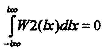
lx ist dabei der Ort auf der Antenne vom Zentrum gemessen und lxo der Abstand vom Rand bis
zum Zentrum der Antenne. Die Funktion W2 ist ideal zur Vermessung der Krümmung eines Feldes.
Sie weist jedoch starke Seitenzipfel auf, die nicht tolerierbar sind. Die Beleuchtungsfunktion J02 soll
daher der Funktion W2 soweit angenähert werden, bis die Seitenzipfel das noch tolerierbare Mass
erreichen. Es sei nun :

Die Kurvatur-Beleuchtungsfunktion ist nun so zu wählen, dass J02(lx) = J02(-lx) ist. Ferner soll unter
Berücksichtigung zulässiger Nebenzipfel P02 maximal sein, wodurch sich eine gute Ankopplung der
Antennenelemente ergibt. Ferner soll Q02=P02m/P02 maximal sein. Q02 ist ein Mass für die Effizienz
des Antennenstrahls F02 bzw. der Beleuchtungsfunktion J02, die Krümmung des Feldes zu
messen. Bevorzugt weist die Beleuchtungsfunktion J02(lx) in der Messdimension zumindest annähernd
folgenden in Fig. 18 gezeigten Verlauf auf:
Diese Funktion entsteht nach der doppelten Ableitung einer für Js(lx) angenommenen Gauss-Funktion. lx0 ist dabei der Ort auf der Apertur, wo die Anregungsamplitude der Gaussfunktion um 1/e½ bzw. die Anregungsleistung um 1/e gegenüber dem Wert im Zentrum abgenommen hat.This function arises after the double derivation of a Gauss function assumed for Js (lx). lx0 is the location on the aperture where the excitation amplitude of the Gaussian function has decreased by 1 / e ½ or the excitation power by 1 / e compared to the value in the center.
Besonders vorteilhaft ist das erfindungsgemässe Verfahren im Zusammenhang mit Radargeräten anwendbar, die zur Durchführung des Sidelobe Suppression (SLS) - Verfahrens geeignet sind, das z.B. in Richard C. Johnson, Antenna Engineering Handbook, Mc Graw-Hill Book Company, New York 1993, dritte Auflage, Kapitel 33, Seiten 33-6 bis 33-8 beschrieben ist. Zusätzlich zu einem Differenz- und einem Summen-Muster (Difference- and Σ-Pattern) wird ein Lücken-Muster (Notch-Pattem) verwendet, das aus dem Summen-Muster durch die Phasenumkehrung der Elementarsignale von Antennenelementen hervorgeht, die in der Mitte der Arrayantenne senkrecht zur Messachse eine Säule bilden. Dieses Lücken-Muster weist eine Ähnlichkeit mit dem in Fig. 13 gezeigten Muster der erfindungsgemäss festgelegten Beleuchtungsfunktion J02(lx) auf. Die dem Lücken-Muster entsprechende Beleuchtungsfunktion der SLS-Arrayantenne entspricht nach Fouriertransformation und Normierung mit der Summenfunktion einer erfindungsgemäss verwendbaren geraden Funktion F2(x). Ein Radarsystem, das zur Durchführung Sidelobe Suppression (SLS) - Verfahrens geeignet ist, kann daher praktisch ohne Handwareänderungen der Antenne zu einem zur Durchführung des erfindungsgemässen Verfahrens geeigneten System erweitert werden. Die beiden in einem Radarsystem vorgesehenen Verfahren zur Unterdrückung von Zielsignalen, die über Nebenkeulen empfangen werden, sowie zur Auflösung von zwei Zielen, die durch die Hauptkeulen erfasst werden, ergänzen sich daher in idealer Weise.The method according to the invention can be used particularly advantageously in connection with radar devices which are suitable for carrying out the sidelobe suppression (SLS) method, which is described, for example, in Richard C. Johnson, Antenna Engineering Handbook, Mc Graw-Hill Book Company, New York 1993, third Edition, chapter 33, pages 33-6 to 33-8. In addition to a difference and a sum pattern (Difference and Σ pattern), a gap pattern (Notch-Pattem) is used, which results from the sum pattern by the phase inversion of the elementary signals from antenna elements, which is in the middle of the Form a column antenna perpendicular to the measuring axis. This gap pattern is similar to the pattern of the lighting function J02 (lx) defined according to the invention shown in FIG. 13. The illumination function of the SLS array antenna corresponding to the gap pattern corresponds, after Fourier transformation and normalization with the sum function, to a straight function F2 (x) which can be used according to the invention. A radar system which is suitable for carrying out the sidelobe suppression (SLS) method can therefore be expanded to a system suitable for carrying out the method according to the invention with practically no manual changes to the antenna. The two methods provided in a radar system for suppressing target signals which are received via side lobes and for resolving two targets which are detected by the main lobes therefore complement one another in an ideal manner.
Die nach dem erfindungsgemässen Verfahren ermittelten Zielrichtungen können auch zur Steuerung der Antenne verwendet werden. Bei der vorzugsweisen Verwendung von elektronisch steuerbaren Antennen wird das Sendediagramm derart eingestellt, dass in bezug auf die Richtung eines Störsignals oder eines auszublendenen Ziels möglichst kein Signal ausgesendet oder empfangen wird.The target directions determined according to the method according to the invention can also be used for control purposes the antenna can be used. With the preferred use of electronically controllable Antennas, the transmission diagram is set so that with respect to the direction of a Interference signal or a target to be hidden, if possible, no signal transmitted or received becomes.
Die zur Bestimmung der Zielablagen x1, x2 (bzw. falls vorgesehen y1, y2) im Prozessor vorhandenen
Daten können ferner zur Bestimmung des Phasenwinkels ϕ zwischen den aus Richtung x1, y1
und x2, y2 eintreffenden Signalen verwendet werden. Für die Werte des Differenzkanals des
Amplituden-Monopulsverfahrens gilt (Index A und ACT sind nicht geschrieben, z.B. F1AqACT →
F1q, F1ApACT → F1p; F1A(x) → F1(x)) :
Anhand der Werte von sin ϕ und cos ϕ kann der Winkel ϕ eindeutig bestimmt werden. Ebenso kann der Winkel ϕ auch mit den Daten des Kurvaturkanals (F1 in den obigen Formeln durch F2 ersetzen) sowie den beim Phasen-Monopulsverfahren verwendeten Daten bestimmt werden. Durch die Messung des Winkels ϕ können echte Zweiziel-Fälle und Reflexions-Fälle voneinander unterschieden sowie ungünstige Phasenlagen erkannt werden, bei denen der Winkel ϕ nahe null oder nahe π wird. The angle ϕ can be clearly determined on the basis of the values of sin ϕ and cos ϕ. Likewise can the angle ϕ also with the data of the curvature channel (replace F1 in the formulas above with F2) as well as the data used in the phase monopulse method. By measurement of the angle ϕ can distinguish real two-target cases from reflection cases as well as unfavorable phase positions are recognized, in which the angle ϕ becomes close to zero or close to π.
Phasendifferenzen ϕ nahe null oder nahe π können z.B. durch eine Änderung der Sendefrequenz vermieden werden. Bei Reflexionen sind die Phasenänderungen zwischen zwei Messungen typischerweise etwa um den Faktor hundert kleiner als bei Zweiziel-Fällen, bei denen die Transponder von zwei Zielen unterschiedliche Sendefrequenzen aufweisen. Damit können Reflexionen von echten Zweizielfällen unterschieden werden. Zwei Zielen kann zudem jeweils eine Differenzfrequenz (Schwebung) zugeordnet werden, die es erlaubt, dieses Zielpaar zu einem späteren Zeitpunkt wieder zu identifizieren.Phase differences ϕ close to zero or close to π can e.g. by changing the transmission frequency be avoided. In the case of reflections, the phase changes between two measurements are typical about a hundred times smaller than in two-target cases where the transponder have different transmission frequencies from two destinations. This allows reflections from real A distinction is made between two target cases. Two targets can also have a difference frequency (Beat) can be assigned, which allows this target pair to be restored at a later time to identify.
Weiterhin können die Verhältnisse L1, L2 der Leistungen der Signale von zwei Zielen aus den
Richtungen x1,y1 und x2,y2 im Verhältnis zur Leistung des Summensignals bestimmt werden.
Nachstehend wird dies für das Amplituden-Monopulsverfahren ausgewiesen (mit Indexzeichen A):
Ebenso können die Leistungsverhältnisse LA1, LA2 auch mit den Daten des Kurvaturkanals sowie den beim Phasen-Monopulsverfahren verwendeten Daten bestimmt werden. Aufgrund der gewonnen Daten können die Ziele markiert und danach einfacher verfolgt werden. Falls zwei Ziele durch das erfindungsgemässe Radarsystem (siehe Fig. 9) erfasst werden, können deren Winkeldaten x1,y1 und x2,y2 erfindungsgemäss bestimmt werden. Falls die Ziele z.B. in einem späteren Moment ihre Positionen vertauschen, wird dies nicht erkannt, falls nur die Winkeldaten x1,y1 und x2,y2 bestimmt werden. Falls vor dem Vertauschen jedoch die Leistungsverhältnisse LA1, LA2 bestimmt wurden, können die Ziele auch nach einem Sendeunterbruch wieder eindeutig identifiziert werden.Likewise, the power ratios L A 1, L A 2 can also be determined using the data of the curvature channel and the data used in the phase monopulse method. Based on the data obtained, the goals can be marked and then more easily followed. If two targets are detected by the radar system according to the invention (see FIG. 9), their angle data x1, y1 and x2, y2 can be determined according to the invention. If the targets swap their positions at a later moment, for example, this is not recognized if only the angle data x1, y1 and x2, y2 are determined. If, however, the power ratios L A 1, L A 2 were determined before the swapping, the targets can be clearly identified again even after a transmission interruption.
Sollen aus einer Leistungsmessung des Summensignals und der bestimmten Leistungsverhältnisse L1 und L2 die effektiven antennenunabhängigen zielspezifischen Leistungen bestimmt werden, ist die Richtungscharakteristik des Summendiagramms in der Richtung des betreffenden Ziels im Vergleich mit der Kalibrationsrichtung als Korrekturfaktor zu berücksichtigen.Should be from a power measurement of the sum signal and the determined power ratios L1 and L2 the effective antenna-independent target-specific services are determined the directional characteristic of the sum diagram in the direction of the target in question with the calibration direction as a correction factor.
Die Ermittlung der Leistungsverhältnisse LA1, LA2 und der zielspezifischen Leistungen kann für verschiedene Zwecke äusserst vorteilhaft eingesetzt werden. Einerseits können die Ziele wie oben beschrieben etikettiert werden, wodurch die Verfolgung dieser Ziel deutlich vereinfacht wird. Ferner kann der Reflexionsfaktor bei gespiegelten Zielen ermittelt werden. Ferner kann festgestellt werden, ob ein Ein- oder ein Zweiziel-Fall vorliegt. Falls die Division der Leistungsverhältnisse LA1, LA2 gegen null oder ∞ geht, liegt ein Einziel-Fall vor. Falls ein Schwellwert nahe bei null oder ∞ unter- bzw. überschritten wird, wird daher das Verfahren zur Ermittlung der Zieldaten gemäss den Formeln (Formel 121) für den Einziel-Fall angewendet. Von Vorteil ist die Ermittlung der Leistungsverhältnisse LA1, LA2 ferner bei der Zielvermessung in zwei Dimensionen. Durch das erfindungsgemässe Verfahren können, wie oben erläutert, Zielablagen x1, x2, y1 und y2 ermittelt werden. Unklar ist vorerst, welche Zielablagen miteinander zu kombinieren sind. Befindet sich das erste Ziel an der Stelle x1, y2 und das zweite Ziel an der Stelle x2, y1 oder befindet sich das erste Ziel an der Stelle x1, y1 und das zweite Ziel an der Stelle x2, y2? Durch die Leistungsmessung kann nun festgestellt werden, welches Paar der Zielablagen x1, y1; x1,y2 bzw. x2, y1; x2,y2 zumindest annähernd dieselben Leistungsverhältnisse LA1 bzw. LA2 aufweist und einem Zielpaar und nicht einem Phantompaar zugehört. Von besonderer Bedeutung ist die Ermittlung der Leistungsverhältnisse LA1, LA2 für die Unterdrückung bzw. Separierungvon Störsignalen (defruiting, degarbeling). Die zugrunde liegenden Einzelsignale können damit identifiziert werden.The determination of the performance ratios L A 1, L A 2 and the target-specific benefits can be used extremely advantageously for various purposes. On the one hand, the goals can be labeled as described above, making it much easier to pursue these goals. The reflection factor can also be determined for mirrored targets. It can also be determined whether there is a one-target or a two-target case. If the division of the performance ratios L A 1, L A 2 goes towards zero or ∞, there is a single-target case. If a threshold value close to zero or ∞ is undershot or exceeded, the procedure for determining the target data according to the formulas (Formula 121) is therefore used for the single-target case. The determination of the power ratios L A 1, L A 2 is also advantageous when measuring the target in two dimensions. As explained above, target deposits x1, x2, y1 and y2 can be determined by the method according to the invention. It is initially unclear which target shelves are to be combined. Is the first target at x1, y2 and the second target at x2, y1 or is the first target at x1, y1 and the second target at x2, y2? The performance measurement can now be used to determine which pair of target shelves x1, y1; x1, y2 or x2, y1; x2, y2 has at least approximately the same power ratios L A 1 and L A 2 and belongs to a target pair and not to a phantom pair. Of particular importance is the determination of the performance ratios L A 1, L A 2 for the suppression or separation of interference signals (defruiting, degarbeling). The underlying individual signals can thus be identified.
Vorteilhaft anwendbar ist ferner die in Fig. 17 gezeigte mit sieben Subarrays versehene Wabenantenne WA, welche ertaubt, zwei Ziele in drei koplanaren Messdimensionen x,y,z zu vermessen und anhand der Messwerte x1, x2, y1, y2, z1, z2 eindeutig zu orten. Die drei Messachsen x,y,z laufen durch die Phasenzentren pz5, pzΩ, pz6; pz3, pzΩ, pz4 bzw. pz1, pzΩ, pz2 von je drei Subarrays und schneiden sich vorzugsweise im Phasenzentrum pzΩ des zentralen Subarrays Ω. Phantom- oder Geistbilder können durch die Verwendung der Messwerte aus der dritten Messdimension vollständig ausgeschaltet werden, ohne dass die Leistungen der einzelnen Signale zu berücksichtigen sind. Dies ergibt den Vorteil, dass die eindeutige Ortung auch möglich ist, wenn die Leistungsverhältnisse beider Zielechosignale gleich sind. Die in Fig. 17 gezeigten Ziele TT1, TT2 liegen dabei an Stellen, die durch Messwerte aus allen drei Messdimensionen bezeichnet sind.The honeycomb antenna provided with seven subarrays shown in FIG. 17 can also be used advantageously WA, which is able to measure two targets in three coplanar dimensions x, y, z and based on the measured values x1, x2, y1, y2, z1, z2. The three measuring axes x, y, z run through the phase centers pz5, pzΩ, pz6; pz3, pzΩ, pz4 or pz1, pzΩ, pz2 of three subarrays each and preferably intersect in the phase center pzΩ of the central subarray Ω. Phantom- or ghost images can be complete by using the measurements from the third measurement dimension be switched off without taking into account the performance of the individual signals are. This gives the advantage that clear location is also possible if the performance ratio both target echo signals are the same. The destinations TT1, TT2 shown in FIG. 17 are present Places that are identified by measurement values from all three measurement dimensions.
Zur präzisen Zielvermessung ist insbesondere beim Empfang nicht kohärenter Ziele (z.B. bei IFF-Empfang von zwei Transpondersignalen mit leicht voneinander abweichender Frequenz) wichtig, dass die Eingangssignale F1pACT, F1qACT, F2pACT, F2qACT gleichzeitig abgetastet werden.For precise target measurement, it is important, especially when receiving non-coherent targets (e.g. IFF reception of two transponder signals with a slightly different frequency) that the input signals F1p ACT , F1q ACT , F2p ACT , F2q ACT are sampled simultaneously.
Es versteht sich, dass die Vermessung der Zieldaten nach dem erfindungsgemässen Verfahren nur bezüglich Lage x1,y1;x2,y2, nur bezüglich der Phase ϕ oder nur bezüglich der Leistungsverhältnisse LA1, LA2, jedoch auch beliebig kombiniert erfolgen kann.It goes without saying that the target data can be measured using the method according to the invention only with respect to position x1, y1; x2, y2, only with respect to phase ϕ or only with regard to the power ratios L A 1, L A 2, but also in any combination.
Claims (31)
- Method for an amplitude or phase monopulse radar for position measurement of a first and, if necessary, a second target (TT1, TT2) from directions x1, y1; x2, y2, detected by the radar beam whose echo signals overlap, with a horn or array antenna (HA; PA) which has at least three subantennas (A, B, Ω) for a measured axis x equipped and arranged such that two linear combinations F01(x) and F02(x) can be formed by their output signals, by means of which, after standardisation with a third linear combination Fs(x) of output signals, two purely real or purely imaginary antenna functions
- Method for an amplitude or phase monopulse radar system for position measurement of a first, and if necessary a second, target (TT1, TT2) from directions x1, y1; x2, y2, detected by the radar beam whose echo signals overlap, with an antenna whose signals are generated by three illumination functions chosen in such a way and transformed to antenna functions F01(x), F02(x), Fs(x), of which the first J01(lx) is provided for measurement of the field slope, second J02(lx) for measurement of the field curvature and the third Js(lx) for measurement of the field intensity, that after standardisation of the antenna functions F01(x), F02(x) with the antenna function Fs(x) two purely real or purely imaginary antenna functions
- Method in accordance with claims 1 or 2, characterised in that one of the functions F1(x), F2(x) is even and the other is odd and/or that the main beam directions of the three subantennas (A, B, Ω) or the extreme values of all illumination functions j01(lx,lsx), j02(lx,lsx), js(lx,lsx) lie in one plane and/or that the radiation diagrams of the three subantennas (A, B, Ω) or the illumination functions j01(lx,lsx), j02(lx,lsx), js(lx,lsx) have a straight symmetrical pattern relative to deviations perpendicular to the measured axis and/or that the functions f1(x,sx), f2(x,sx), fs(x,sx) have function patterns perpendicular to the measured axis, which differ from each other only by a proportionality factor.
- Method in accordance with claims 1, 2 or 3, performed with a horn or antenna array (HA; PA) which for the first measured axis x (e.g. azimuth) has a first group of three subantennas or a first group of three illumination functions J01(lx), J02(lx) Js(lx) and which for a second measured axis y (e.g. elevation) has a second group of three subantennas (Ω, C, D) or a second group of three illumination functions J01(ly), J02(ly), Js(ly) and that preferably one subantenna (Ω) or one illumination function js(lx,ly) with js(lx,0) = Js(lx); js(0,ly) = Js(ly) is common to both groups.
- Method in accordance with claims 1, 2, 3 or 4, characterised in that the target deviations (x1, x2 or y1, y2) can be approximately calculated in that the functions F2(x) or F2(y) are replaced by F2(0).
- Method in accordance with one of claims 1 to 5, characterised in that the pattern of the even illumination functions J02(x) or J02(y) provided for measurement of the curvature correspond at least approximately to the pattern of function
- Method in accordance with one of claims 1 to 6, characterised in that the ratio of the antenna functions F02(x) / Fs(x) in the single-target case is proportional at least close to the square of the angular deviation and/or is equal to zero on the boresight axis (no angular deviation).
- Method in accordance with one of claims 1 to 7, characterised in that the control, SLS or omnidirectional beam function of a corresponding antenna system is used as the antenna function F02(x).
- Method in accordance with one of claims 1 to 8, characterised in that the signals F1ACT, F2ACT formed in the input stages (AF, NM) of the radar are divided in a further stage (QG) into in-phase elements F1pACT, F2pACT and into quadrature elements F1qACT, F2qACT and scanned simultaneously.
- Method particularly in accordance with one of claims 1 to 9, characterised in that the phase difference ϕ between signals arriving from two directions are measured and it is determined whether a real two-target case or a reflection case and/or also phase angles are detected which are unsatisfactory for the measurement, at which the angle ϕ is close to zero or close to π and which could be avoided, for example by changing the transmission frequency.
- Method particularly in accordance with one of claims 1 to 10, characterised in that the ratios L1, L2 of the powers of the signals from two targets from directions x1, y1 and x2, y2 are determined relative to the power of the summation signal, that in the case of a reflection, the reflection factor is determined using the established power ratio L1, L2 of the reflection factor and/or that if the quotient L1/L2 formed by the power ratios L1, L2 is sufficiently close to zero or ∞, the calculation of the target data is carried out for the single-target case and/or that the localised targets are labelled with the associated power ratios L1, L2, which when tracking a target are checked preferably at each measuring interval, so that the relevant target can be distinguished from other targets or sources of interference and/or that the power ratios LA1, LA2 are assigned to the target deviations x1, x2, y1 and y2 during target measurement in two dimensions and it is finally determined which pair of the target deviations x1, y1; x1, y2 or x2, y1; x2, y2 belongs to the first and second targets.
- Method in accordance with one of claims 1 to 11, characterised in that an electronically-controllable antenna is used whose transmission diagram is preferably set in a manner such that no signal is transmitted and/or received relative to the direction of an interference signal or a target to be blanked out.
- Method in accordance with claim 1 or in accordance with one of claims 1 to 12, characterised in that the signals of the subantennas (A, B, Ω or Ω, C, D) provided for each direction of measurement are preferably weighted in a weighting network provided in the antenna unit, by factors R, S, T; E, G and H so that for each direction of measurement x;y an odd slope function F01(x); F01(y), an even curvature function F02(x); F02(y) and a summation function Fs(x); Fs(y) are formed.
- Method in accordance with one of claims 1 to 13, characterised in that illumination functions j01(lx,lsx); j01(ly,lsy), j02(lx,lsx); j02(ly,lsy), js(lx,lsx); js(ly,lsy) and/or antenna functions f01(x,sx); f01(y,sy), f02(x,sx); f02(y,sy), fs(x,sx); fs(y,sy) are chosen which can be represented as a product from an element J01(lx); J01(ly), J02(lx); J02(ly), Js(lx); Js(ly) or F01(x); F01(y), F02(x); F02(y), Fs(x); Fs(y) in direction of measurement x,y and an element J01(lsx); J01(lsy), J02(lsx); J02(lsy), Js(lsx); Js(lsy) in the direction of perpendiculars lsx, lsy to lx, ly and perpendiculars sx, sy relative to the direction of measurement x,y.
- Method in accordance with one of claims 1 to 14, characterised in that the determination of the target data is based on the amplitude and/or phase monopulse method.
- Method in accordance with one of claims 1 to 15, characterised in that for determination of the target data in the single-target case at least one of the following equations is used:
- Method in accordance with one of claims 1 to 16, characterised in that the measurement is preferably carried out with a honeycomb antenna with seven subarrays for three measurement dimensions x, y and z in one plane and it is determined which target directions on the basis of the measurements in the three directions of measurement, x, y and z can be determined in conformity.
- Amplitude or phase monopulse radar for position measurement of a first, and if necessary, a second, target (TT1, TT2) from directions x1, y1; x2, y2, detected by the radar beam, whose echo signals overlap, with a horn or array antenna (HA; PA) which for a first measured axis x has at least three subantennas (A, B, Ω) configured and arranged such that with their output signals two linear combination F01(x) and F02(x) can be formed, by means of which, after standardisation with a third linear combination Fs(x) of output signals, two antenna functions
- Amplitude or phase monopulse radar system for position measurement of a first, and if necessary a second, target (TT1, TT2) from directions x1, y1; x2, y2, detected by the radar beam, whose echo signals overlap, with an antenna whose signals are generated by three illumination functions, chosen in such a way and transformed to antenna functions F01(x), F02(x), Fs(x), of which the first J01(lx) is provided for measurement of the field slope, the second J02(lx) is provided for measurement of the field curvature and the third Js(lx) for measurement of the field intensity, that after standardisation of the antenna functions F01(x), F02(x) with the antenna function Fs(x) two antenna functions
- Monopulse radar in accordance with claim 18 or 19, characterised in that one of the functions F1(x), F2(x) is even and the other is odd and/or that the direction of the main beam of the three subantennas (A, B, Ω) or the extreme values of all illumination functions j01(lx,lsx), j02(lx,lsx), js(lx,lsx) lie in one plane and/or that the radiation diagram of the three subantennas (A, B, Ω) or the illumination functions j01(lx,lsx), j02(lx,lsx), js(lx,lsx) have an even symmetry pattern relative to deviations perpendicular to the measured axis and/or that the functions f1(x,sx), f2(x,sx), fs(x,sx) have function patterns perpendicular to the measured axis which differ only by a proportionality factor.
- Monopulse radar in accordance with claims 18, 19 or 20, characterised in that a horn or array antenna (HA; PA) is provided, which for the first measured axis x (e.g. azimuth) has a first group of three subantennas or a first group of three illumination functions J01(lx), J02(lx), Js(lx) and which for a second measured axis y (e.g. elevation) has a second group of three subantennas (Ω, C, D) or a second group of three illumination functions J01(ly), J02(ly), Js(ly) and that preferably one subantenna (Ω) or one illumination function js(lx,ly) where js(lx,0) = Js(lx); js(0,ly) = Js(ly) is common to both groups.
- Monopulse radar in accordance with claims 19, 20 or 21, characterised in that the pattern of the even illumination functions J02(x) or J02(y) provided for measurement of the curvature at least approximately correspond to the pattern of the function
- Monopulse radar in accordance with one of claims 18 to 22, characterised in that the antenna has a control, SLS or omnidirectional beam function which is used as a curvature function F02(x) or F02(y).
- Monopulse radar in accordance with one of claims 18 to 23, characterised in that the phase difference ϕ between signals arriving from two directions and/or the ratios L1, L2 of the powers of the signals from two targets from directions x1, y1 and x2, y2 can be measured and assessed relative to the power of the summation signal.
- Monopulse radar in accordance with one of claims 18 to 24, characterised in that the antenna (PA) can be electronically controlled and its transmission diagram preferably set such that where possible no signal can be transmitted and/or received relative to the direction of an interference signal or a target to be blanked out.
- Monopulse radar in accordance with claims 18 to 25, characterised in that a network (AF) and also a division stage (NM) are provided which form the signals F1 ACT, F2 ACT from the output signals of subantennas (A, B, Ω or Ω, C, D) and that in a further stage (QG) they are divided into in-phase elements F1pACT, F2pACT and quadrature elements F1qACT, F2qACT.
- Monopulse radar in accordance with one of claims 18 to 26, characterised in that the amplitude monopulse antenna has three subantennas (A, B, Ω or Ω, C, D) for each measured axis x;y, each of which has a common phase centre and whose radiation axes for each measured axis lie in one plane or that the phase monopulse antenna for each measured axis x;y has three subantennas (A, B, Ω or Ω, C, D) whose phase centres for each measured axis lie on a common straight line and whose radiation axes run parallel to each other.
- Monopulse radar in accordance with one of claims 18 to 27, characterised in that the amplitude monopulse antenna or the phase monopulse antenna is an array antenna with several antenna elements (AE), which are provided individually, or assembled in groups, to form the subantennas (A, B, Ω or Ω, C, D).
- Monopulse radar in accordance with one of claims 18 to 28, characterised in that the phase centres of the subantennas (A, B, Ω or C, D, Ω) are arranged such that the phase centre of the subantenna (Ω) is enclosed at equal distances between the phase centres of the subantennas (A and B and/or C and D) and/or that the radiation axes of the subantennas (A and Ω or C and Ω) enclose the same angle as the axes of the subantennas (Ω and B or Ω and D) and/or that the diagrams of the subantennas (A and B or C and D) have an amplitude pattern which is at least approximately equal and/or that the diagrams of the subantennas (A and B or C and D) have a straight symmetry relative to the boresight axis and that the diagram of the subantennas (Ω) contains the boresight axis bx of the expanded monopulse antenna (HA, PA) as an axis for a straight symmetry.
- Monopulse radar in accordance with one of claims 18 to 29, for measuring the targets in three angular dimensions, characterised in that the antenna (WA) has the shape of a honeycomb, with preferably seven subarrays, whose phase centres pz5, pzΩ, pz6; pz3, pzΩ, pz4 or pz1, pzΩ,pz2 run in three measuring axes x,y,z which intersect in the phase centre pzΩ of the central subarray.
- Monopulse radar equipment in accordance with one of claims 18 to 30, characterised in that a processor (PROC) is provided, which operates in accordance with the pipeline method and/or approximates in a first step to the stored functions F1, F2 by polynomials of third degree and analytically solves the equations, and/or uses the solutions obtained in this way preferably as an initial approach for an iterative method.
Applications Claiming Priority (4)
| Application Number | Priority Date | Filing Date | Title |
|---|---|---|---|
| CH359095 | 1995-12-19 | ||
| CH359095 | 1995-12-19 | ||
| CH3590/95 | 1995-12-19 | ||
| PCT/CH1996/000124 WO1997022890A1 (en) | 1995-12-19 | 1996-04-09 | Process and amplitude or phase-single pulse radar device for locating flying objects |
Publications (2)
| Publication Number | Publication Date |
|---|---|
| EP0809811A1 EP0809811A1 (en) | 1997-12-03 |
| EP0809811B1 true EP0809811B1 (en) | 2001-07-11 |
Family
ID=4259267
Family Applications (1)
| Application Number | Title | Priority Date | Filing Date |
|---|---|---|---|
| EP96907242A Expired - Lifetime EP0809811B1 (en) | 1995-12-19 | 1996-04-09 | Process and amplitude or phase-single pulse radar device for locating flying objects |
Country Status (7)
| Country | Link |
|---|---|
| US (1) | US5784022A (en) |
| EP (1) | EP0809811B1 (en) |
| AT (1) | ATE203109T1 (en) |
| CA (1) | CA2214285C (en) |
| DE (1) | DE59607276D1 (en) |
| DK (1) | DK0809811T3 (en) |
| WO (1) | WO1997022890A1 (en) |
Cited By (1)
| Publication number | Priority date | Publication date | Assignee | Title |
|---|---|---|---|---|
| US10514443B2 (en) * | 2016-09-28 | 2019-12-24 | Robert Bosch Gmbh | Method for evaluating radar radiation, and radar apparatus |
Families Citing this family (30)
| Publication number | Priority date | Publication date | Assignee | Title |
|---|---|---|---|---|
| EP0942294A3 (en) * | 1998-03-09 | 2000-06-07 | Siemens Schweiz AG (Siemens Suisse SA) (Siemens Svizzera SA) Siemens Switzerland Ltd) | Method for the reduction of the sidelobes and amplitude or phase monopulse apparatus |
| SE513939C2 (en) * | 1998-06-24 | 2000-11-27 | Combitech Traffic Syst Ab | Device for position determination by radio waves |
| US6388755B1 (en) * | 1998-12-03 | 2002-05-14 | Advanced Optical Technologies, Inc. | Wireless position and orientation detecting system |
| US7777675B2 (en) | 1999-03-05 | 2010-08-17 | Era Systems Corporation | Deployable passive broadband aircraft tracking |
| US7908077B2 (en) | 2003-06-10 | 2011-03-15 | Itt Manufacturing Enterprises, Inc. | Land use compatibility planning software |
| US7570214B2 (en) | 1999-03-05 | 2009-08-04 | Era Systems, Inc. | Method and apparatus for ADS-B validation, active and passive multilateration, and elliptical surviellance |
| US7782256B2 (en) | 1999-03-05 | 2010-08-24 | Era Systems Corporation | Enhanced passive coherent location techniques to track and identify UAVs, UCAVs, MAVs, and other objects |
| US7667647B2 (en) | 1999-03-05 | 2010-02-23 | Era Systems Corporation | Extension of aircraft tracking and positive identification from movement areas into non-movement areas |
| US8446321B2 (en) | 1999-03-05 | 2013-05-21 | Omnipol A.S. | Deployable intelligence and tracking system for homeland security and search and rescue |
| US7889133B2 (en) | 1999-03-05 | 2011-02-15 | Itt Manufacturing Enterprises, Inc. | Multilateration enhancements for noise and operations management |
| US8203486B1 (en) | 1999-03-05 | 2012-06-19 | Omnipol A.S. | Transmitter independent techniques to extend the performance of passive coherent location |
| US7739167B2 (en) | 1999-03-05 | 2010-06-15 | Era Systems Corporation | Automated management of airport revenues |
| US6404379B1 (en) * | 2000-06-29 | 2002-06-11 | Lockheed Martin Corporation | Matrix monopulse ratio radar processor for two target azimuth and elevation angle determination |
| US6356231B1 (en) * | 2000-06-29 | 2002-03-12 | Lockheed Martin Corporation | Monopulse radar processor for resolving two sources |
| FR2817973A1 (en) * | 2000-12-13 | 2002-06-14 | Imra Europe Sa | Method of detecting the position of objects, used e.g. for assisting in parking of a motor vehicle, is based on two steps for forming beams using a network of ultrasound sensors |
| US6759983B2 (en) | 2001-03-28 | 2004-07-06 | Strategic Analysis, Inc. | Method and device for precise geolocation of low-power, broadband, amplitude-modulated signals |
| US6597312B1 (en) | 2002-01-30 | 2003-07-22 | Northrop Grumman Corporation | Phased array antenna system generating multiple beams having a common phase center |
| JP2005156337A (en) * | 2003-11-26 | 2005-06-16 | Hitachi Ltd | On-vehicle radar device |
| DE102004004492A1 (en) * | 2004-01-29 | 2005-08-18 | Robert Bosch Gmbh | Radar system for motor vehicles |
| US7965227B2 (en) | 2006-05-08 | 2011-06-21 | Era Systems, Inc. | Aircraft tracking using low cost tagging as a discriminator |
| US7821443B2 (en) * | 2008-02-12 | 2010-10-26 | Infineon Technologies Ag | Dual mode radar methods and systems |
| JP2009265007A (en) * | 2008-04-28 | 2009-11-12 | Hitachi Ltd | Mobile radar and planar antenna |
| JP5811931B2 (en) * | 2012-04-04 | 2015-11-11 | トヨタ自動車株式会社 | Phase monopulse radar device |
| DE102012016475B4 (en) * | 2012-08-17 | 2022-09-08 | Hensoldt Sensors Gmbh | Direction finding method based on the monopulse principle |
| DE102014104273A1 (en) * | 2014-03-26 | 2015-10-01 | Friedrich-Alexander-Universität Erlangen-Nürnberg | Method in a radar system, radar system or apparatus of a radar system |
| JP6415386B2 (en) * | 2015-05-28 | 2018-10-31 | 三菱電機株式会社 | Angle measuring device, radar device, and angle measuring method |
| WO2017118621A1 (en) | 2016-01-04 | 2017-07-13 | Symeo Gmbh | Method and system for reducing interference caused by phase noise in a radar system |
| DE102017110063A1 (en) * | 2017-03-02 | 2018-09-06 | Friedrich-Alexander-Universität Erlangen-Nürnberg | Method and device for environment detection |
| RU2696095C1 (en) * | 2019-02-20 | 2019-07-31 | Акционерное общество "Концерн "Созвездие" | Method for two-dimensional monopulse direction finding of radio emission sources |
| CN112083382B (en) * | 2020-09-15 | 2022-08-02 | 四川九洲空管科技有限责任公司 | High-precision small phased array secondary radar azimuth compensation calculation method |
Family Cites Families (2)
| Publication number | Priority date | Publication date | Assignee | Title |
|---|---|---|---|---|
| CH592887A5 (en) * | 1975-05-22 | 1977-11-15 | Siemens Ag Albis | |
| CH629898A5 (en) * | 1978-02-09 | 1982-05-14 | Siemens Ag Albis | ARRANGEMENT FOR IMPROVING ANGLE MEASUREMENT ON A FOLLOWING RADAR. |
-
1996
- 1996-04-09 WO PCT/CH1996/000124 patent/WO1997022890A1/en active IP Right Grant
- 1996-04-09 EP EP96907242A patent/EP0809811B1/en not_active Expired - Lifetime
- 1996-04-09 AT AT96907242T patent/ATE203109T1/en not_active IP Right Cessation
- 1996-04-09 CA CA002214285A patent/CA2214285C/en not_active Expired - Fee Related
- 1996-04-09 DE DE59607276T patent/DE59607276D1/en not_active Expired - Fee Related
- 1996-04-09 DK DK96907242T patent/DK0809811T3/en active
- 1996-04-09 US US08/817,703 patent/US5784022A/en not_active Expired - Fee Related
Cited By (1)
| Publication number | Priority date | Publication date | Assignee | Title |
|---|---|---|---|---|
| US10514443B2 (en) * | 2016-09-28 | 2019-12-24 | Robert Bosch Gmbh | Method for evaluating radar radiation, and radar apparatus |
Also Published As
| Publication number | Publication date |
|---|---|
| EP0809811A1 (en) | 1997-12-03 |
| DK0809811T3 (en) | 2001-10-22 |
| CA2214285C (en) | 2001-06-05 |
| DE59607276D1 (en) | 2001-08-16 |
| ATE203109T1 (en) | 2001-07-15 |
| CA2214285A1 (en) | 1997-06-26 |
| US5784022A (en) | 1998-07-21 |
| WO1997022890A1 (en) | 1997-06-26 |
Similar Documents
| Publication | Publication Date | Title |
|---|---|---|
| EP0809811B1 (en) | Process and amplitude or phase-single pulse radar device for locating flying objects | |
| DE102009046499B4 (en) | radar device | |
| DE60302379T2 (en) | Radar processing system and method for detecting and monitoring targets | |
| DE102010002474B4 (en) | Radar apparatus for suppressing effects of grating lobes in detecting a direction of a target based on a phase difference between received reflected waves | |
| DE112008000513B4 (en) | Electronically scanning radar system | |
| DE102011088045B4 (en) | Phased array antenna and phase calibration method | |
| DE60109990T2 (en) | Monopulse radar processor for determining the azimuth and elevation angles of two targets over a matrix of amplitude ratios | |
| DE2650832A1 (en) | PULSE RADAR UNIT WITH MECHANICAL AND ELECTRONIC BEAM SWIVEL | |
| EP3534178B1 (en) | Radar apparatus with antenna array and method for source location using a two-dimensional antenna array | |
| DE102018207686A1 (en) | MIMO radar sensor for motor vehicles | |
| DE60027418T2 (en) | PROCESS FOR DISPLAYING EXCEPT AXIAL SIGNALS FOR MONOPULAR RADAR | |
| EP0942294A2 (en) | Method for the reduction of the sidelobes and amplitude or phase monopulse apparatus | |
| DE2306407B2 (en) | Antenna system with high angular resolution for radar devices with separate transmitting and receiving antennas | |
| DE102018200765A1 (en) | FMCW radar sensor | |
| DE3136625C1 (en) | Wide-aperture direction finder | |
| DE2929254C2 (en) | Antenna system for direction finding of a microwave signal source | |
| DE2429072A1 (en) | PULSE DOPPLER RADAR | |
| DE10012080C1 (en) | Antenna array and method for operating an antenna array | |
| DE102017120368A1 (en) | Method and apparatus for generating a modulated continuous wave radar signal | |
| EP1676145A1 (en) | Method and device for the radio determination of a number of spectrally overlapping radio stations | |
| EP3082273A1 (en) | Method and device for reduction of correlated interference in multichannel receiver systems correlated with digital beam forming | |
| DE2226435A1 (en) | Radio interferometer | |
| DE60133222T2 (en) | INTERFEROMETIC SYNTHETIC SONARANTENNE | |
| EP1500952A2 (en) | Method of direction detemination for multiple target situations for multi-lobe monopulse radar | |
| EP0108094B1 (en) | Radiogoniometric device |
Legal Events
| Date | Code | Title | Description |
|---|---|---|---|
| PUAI | Public reference made under article 153(3) epc to a published international application that has entered the european phase |
Free format text: ORIGINAL CODE: 0009012 |
|
| AK | Designated contracting states |
Kind code of ref document: A1 Designated state(s): AT BE CH DE DK ES FI FR GB GR IE IT LI LU MC NL PT SE |
|
| 17P | Request for examination filed |
Effective date: 19971229 |
|
| 17Q | First examination report despatched |
Effective date: 19981012 |
|
| GRAG | Despatch of communication of intention to grant |
Free format text: ORIGINAL CODE: EPIDOS AGRA |
|
| GRAG | Despatch of communication of intention to grant |
Free format text: ORIGINAL CODE: EPIDOS AGRA |
|
| GRAH | Despatch of communication of intention to grant a patent |
Free format text: ORIGINAL CODE: EPIDOS IGRA |
|
| GRAH | Despatch of communication of intention to grant a patent |
Free format text: ORIGINAL CODE: EPIDOS IGRA |
|
| GRAA | (expected) grant |
Free format text: ORIGINAL CODE: 0009210 |
|
| AK | Designated contracting states |
Kind code of ref document: B1 Designated state(s): AT BE CH DE DK ES FI FR GB GR IE IT LI LU MC NL PT SE |
|
| PG25 | Lapsed in a contracting state [announced via postgrant information from national office to epo] |
Ref country code: IT Free format text: LAPSE BECAUSE OF FAILURE TO SUBMIT A TRANSLATION OF THE DESCRIPTION OR TO PAY THE FEE WITHIN THE PRE;WARNING: LAPSES OF ITALIAN PATENTS WITH EFFECTIVE DATE BEFORE 2007 MAY HAVE OCCURRED AT ANY TIME BEFORE 2007. THE CORRECT EFFECTIVE DATE MAY BE DIFFERENT FROM THE ONE RECORDED.SCRIBED TIME-LIMIT Effective date: 20010711 Ref country code: IE Free format text: LAPSE BECAUSE OF FAILURE TO SUBMIT A TRANSLATION OF THE DESCRIPTION OR TO PAY THE FEE WITHIN THE PRESCRIBED TIME-LIMIT Effective date: 20010711 Ref country code: FI Free format text: LAPSE BECAUSE OF FAILURE TO SUBMIT A TRANSLATION OF THE DESCRIPTION OR TO PAY THE FEE WITHIN THE PRESCRIBED TIME-LIMIT Effective date: 20010711 |
|
| REF | Corresponds to: |
Ref document number: 203109 Country of ref document: AT Date of ref document: 20010715 Kind code of ref document: T |
|
| REG | Reference to a national code |
Ref country code: CH Ref legal event code: EP |
|
| GBT | Gb: translation of ep patent filed (gb section 77(6)(a)/1977) |
Effective date: 20010711 |
|
| REF | Corresponds to: |
Ref document number: 59607276 Country of ref document: DE Date of ref document: 20010816 |
|
| REG | Reference to a national code |
Ref country code: IE Ref legal event code: FG4D Free format text: GERMAN |
|
| PG25 | Lapsed in a contracting state [announced via postgrant information from national office to epo] |
Ref country code: PT Free format text: LAPSE BECAUSE OF FAILURE TO SUBMIT A TRANSLATION OF THE DESCRIPTION OR TO PAY THE FEE WITHIN THE PRESCRIBED TIME-LIMIT Effective date: 20011011 |
|
| PG25 | Lapsed in a contracting state [announced via postgrant information from national office to epo] |
Ref country code: GR Free format text: LAPSE BECAUSE OF FAILURE TO SUBMIT A TRANSLATION OF THE DESCRIPTION OR TO PAY THE FEE WITHIN THE PRESCRIBED TIME-LIMIT Effective date: 20011012 |
|
| REG | Reference to a national code |
Ref country code: DK Ref legal event code: T3 |
|
| ET | Fr: translation filed | ||
| REG | Reference to a national code |
Ref country code: GB Ref legal event code: IF02 |
|
| PG25 | Lapsed in a contracting state [announced via postgrant information from national office to epo] |
Ref country code: ES Free format text: LAPSE BECAUSE OF FAILURE TO SUBMIT A TRANSLATION OF THE DESCRIPTION OR TO PAY THE FEE WITHIN THE PRESCRIBED TIME-LIMIT Effective date: 20020131 |
|
| PG25 | Lapsed in a contracting state [announced via postgrant information from national office to epo] |
Ref country code: MC Free format text: LAPSE BECAUSE OF NON-PAYMENT OF DUE FEES Effective date: 20020409 Ref country code: LU Free format text: LAPSE BECAUSE OF NON-PAYMENT OF DUE FEES Effective date: 20020409 Ref country code: GB Free format text: LAPSE BECAUSE OF NON-PAYMENT OF DUE FEES Effective date: 20020409 Ref country code: AT Free format text: LAPSE BECAUSE OF NON-PAYMENT OF DUE FEES Effective date: 20020409 |
|
| PG25 | Lapsed in a contracting state [announced via postgrant information from national office to epo] |
Ref country code: SE Free format text: LAPSE BECAUSE OF NON-PAYMENT OF DUE FEES Effective date: 20020410 |
|
| PG25 | Lapsed in a contracting state [announced via postgrant information from national office to epo] |
Ref country code: LI Free format text: LAPSE BECAUSE OF NON-PAYMENT OF DUE FEES Effective date: 20020430 Ref country code: DK Free format text: LAPSE BECAUSE OF NON-PAYMENT OF DUE FEES Effective date: 20020430 Ref country code: CH Free format text: LAPSE BECAUSE OF NON-PAYMENT OF DUE FEES Effective date: 20020430 Ref country code: BE Free format text: LAPSE BECAUSE OF NON-PAYMENT OF DUE FEES Effective date: 20020430 |
|
| PLBE | No opposition filed within time limit |
Free format text: ORIGINAL CODE: 0009261 |
|
| STAA | Information on the status of an ep patent application or granted ep patent |
Free format text: STATUS: NO OPPOSITION FILED WITHIN TIME LIMIT |
|
| 26N | No opposition filed | ||
| PG25 | Lapsed in a contracting state [announced via postgrant information from national office to epo] |
Ref country code: NL Free format text: LAPSE BECAUSE OF NON-PAYMENT OF DUE FEES Effective date: 20021101 Ref country code: DE Free format text: LAPSE BECAUSE OF NON-PAYMENT OF DUE FEES Effective date: 20021101 |
|
| EUG | Se: european patent has lapsed |
Ref document number: 96907242.0 |
|
| GBPC | Gb: european patent ceased through non-payment of renewal fee |
Effective date: 20020409 |
|
| REG | Reference to a national code |
Ref country code: CH Ref legal event code: PL |
|
| REG | Reference to a national code |
Ref country code: DK Ref legal event code: EBP |
|
| PG25 | Lapsed in a contracting state [announced via postgrant information from national office to epo] |
Ref country code: FR Free format text: LAPSE BECAUSE OF NON-PAYMENT OF DUE FEES Effective date: 20021231 |
|
| NLV4 | Nl: lapsed or anulled due to non-payment of the annual fee |
Effective date: 20021101 |
|
| REG | Reference to a national code |
Ref country code: FR Ref legal event code: ST |