EP0808983A1 - Door closer - Google Patents
Door closer Download PDFInfo
- Publication number
- EP0808983A1 EP0808983A1 EP97108019A EP97108019A EP0808983A1 EP 0808983 A1 EP0808983 A1 EP 0808983A1 EP 97108019 A EP97108019 A EP 97108019A EP 97108019 A EP97108019 A EP 97108019A EP 0808983 A1 EP0808983 A1 EP 0808983A1
- Authority
- EP
- European Patent Office
- Prior art keywords
- door
- door leaf
- narrow side
- spring
- door closer
- Prior art date
- Legal status (The legal status is an assumption and is not a legal conclusion. Google has not performed a legal analysis and makes no representation as to the accuracy of the status listed.)
- Withdrawn
Links
- 238000013016 damping Methods 0.000 claims description 6
- 238000004804 winding Methods 0.000 abstract 1
- 230000005540 biological transmission Effects 0.000 description 3
- 238000009434 installation Methods 0.000 description 3
- 229910000831 Steel Inorganic materials 0.000 description 2
- 238000000034 method Methods 0.000 description 2
- 239000010959 steel Substances 0.000 description 2
- 238000010276 construction Methods 0.000 description 1
- 230000007423 decrease Effects 0.000 description 1
- 230000000694 effects Effects 0.000 description 1
- 238000010438 heat treatment Methods 0.000 description 1
- 239000010720 hydraulic oil Substances 0.000 description 1
- 230000001771 impaired effect Effects 0.000 description 1
- 238000004519 manufacturing process Methods 0.000 description 1
- 238000013017 mechanical damping Methods 0.000 description 1
- 239000003921 oil Substances 0.000 description 1
- 230000036316 preload Effects 0.000 description 1
Images

Classifications
-
- E—FIXED CONSTRUCTIONS
- E05—LOCKS; KEYS; WINDOW OR DOOR FITTINGS; SAFES
- E05F—DEVICES FOR MOVING WINGS INTO OPEN OR CLOSED POSITION; CHECKS FOR WINGS; WING FITTINGS NOT OTHERWISE PROVIDED FOR, CONCERNED WITH THE FUNCTIONING OF THE WING
- E05F1/00—Closers or openers for wings, not otherwise provided for in this subclass
- E05F1/08—Closers or openers for wings, not otherwise provided for in this subclass spring-actuated, e.g. for horizontally sliding wings
- E05F1/10—Closers or openers for wings, not otherwise provided for in this subclass spring-actuated, e.g. for horizontally sliding wings for swinging wings, e.g. counterbalance
-
- E05Y2201/499—
-
- E—FIXED CONSTRUCTIONS
- E05—LOCKS; KEYS; WINDOW OR DOOR FITTINGS; SAFES
- E05Y—INDEXING SCHEME RELATING TO HINGES OR OTHER SUSPENSION DEVICES FOR DOORS, WINDOWS OR WINGS AND DEVICES FOR MOVING WINGS INTO OPEN OR CLOSED POSITION, CHECKS FOR WINGS AND WING FITTINGS NOT OTHERWISE PROVIDED FOR, CONCERNED WITH THE FUNCTIONING OF THE WING
- E05Y2201/00—Constructional elements; Accessories therefore
- E05Y2201/60—Suspension or transmission members; Accessories therefore
- E05Y2201/622—Suspension or transmission members elements
- E05Y2201/644—Flexible elongated pulling elements; Members cooperating with flexible elongated pulling elements
-
- E—FIXED CONSTRUCTIONS
- E05—LOCKS; KEYS; WINDOW OR DOOR FITTINGS; SAFES
- E05Y—INDEXING SCHEME RELATING TO HINGES OR OTHER SUSPENSION DEVICES FOR DOORS, WINDOWS OR WINGS AND DEVICES FOR MOVING WINGS INTO OPEN OR CLOSED POSITION, CHECKS FOR WINGS AND WING FITTINGS NOT OTHERWISE PROVIDED FOR, CONCERNED WITH THE FUNCTIONING OF THE WING
- E05Y2600/00—Mounting or coupling arrangements for elements provided for in this subclass
- E05Y2600/40—Mounting location; Visibility of the elements
- E05Y2600/46—Mounting location; Visibility of the elements in or on the wing
-
- E—FIXED CONSTRUCTIONS
- E05—LOCKS; KEYS; WINDOW OR DOOR FITTINGS; SAFES
- E05Y—INDEXING SCHEME RELATING TO HINGES OR OTHER SUSPENSION DEVICES FOR DOORS, WINDOWS OR WINGS AND DEVICES FOR MOVING WINGS INTO OPEN OR CLOSED POSITION, CHECKS FOR WINGS AND WING FITTINGS NOT OTHERWISE PROVIDED FOR, CONCERNED WITH THE FUNCTIONING OF THE WING
- E05Y2900/00—Application of doors, windows, wings or fittings thereof
- E05Y2900/10—Application of doors, windows, wings or fittings thereof for buildings or parts thereof
- E05Y2900/13—Application of doors, windows, wings or fittings thereof for buildings or parts thereof characterised by the type of wing
- E05Y2900/132—Doors
Definitions
- the invention relates to a door closer with a sliding part guided in a guide, which is acted upon by spring means and which is connected to a closer shaft via a pulling part and can at least partially be wound on a rotary part attached to the closer shaft.
- So-called overhead door closers are known, which are attached to the upper edge of the door leaf or to the upper frame part of the door frame.
- a linkage which can be designed as a scissor linkage or as a sliding arm linkage and which is arranged between the frame and the door leaf, transmits the forces for closing the door.
- Such an overhead door closer is known for example from DE 36 38 353. It has a piston which is guided in a housing and is loaded by a spring and is connected via a gear to the closer shaft to which the linkage is attached. The power transmission between the piston and the transmission takes place by means of a lever. Furthermore, for example from US 2,528,904 a door closer is known which uses a pulling part for power transmission instead of the lever. All such door closers have in common that on the one hand they effect the closing process and at the same time dampen the movement of the door leaf. The damping is ensured by the fact that the piston is in hydraulic oil moves, which is led from the pressure chamber into the return chamber via narrow connecting channels.
- the size of the door closer is too large for it to be conveniently inserted into the leaf of a door.
- the functional unit must be arranged on the upper narrow side of the door leaf, since the linkage arranged at the top of the door frame is to be connected to the closer shaft.
- the attachment of the hydraulic unit on the upper narrow side of the door leaf is particularly disadvantageous since this area becomes particularly hot in the event of a fire due to the heat spreading upwards. As a result, the function of the hydraulic unit is impaired in the situation when it should cause the door to close properly. The use of such a door closer for a fire door is therefore extremely problematic.
- the object of the invention is to provide a door closer, the spring unit serving as an energy store can be installed anywhere in the door leaf and which offers high operational reliability.
- the door closer according to the invention can be attached separately from the damping device. Since no hydraulic components are required in the energy store, it can be built particularly compactly and arranged as a small unit within the door leaf. It is particularly advantageous that the installation space of the door closer is comparatively small and that the upper part of the door is therefore less sensitive to the heating load and warps less.
- the door closer has a separate spring unit with a space in which a spring element is arranged, in particular in the form of a spiral spring, which acts on a sliding part advantageously guided in the space by a rail.
- a traction device is attached to the sliding part, which transmits the spring force to a drum unit.
- the drum unit has a rotating part which is connected to the closer shaft and on which the traction means can be wound up.
- the spring unit and the drum unit are advantageously installed in separate housings which can each be installed in a separate recess in the door leaf.
- the spring unit can be installed in the upper narrow side near the "outer narrow side" which has the lock and is opposite the inner narrow side .
- Such an installation is advantageous because the spring tension can be done via a screw easily accessible from the outer narrow side.
- the spring force is transmitted with the traction means, which is designed in particular as a rope or belt.
- the traction means can be deflected vertically via deflection rollers and aligned in such a way that it runs undisturbed in a channel-shaped recess provided in the door leaf in the upper narrow side.
- the spring unit is built into the inner narrow side of the door leaf. It is particularly advantageous if the spring unit is arranged as deep as possible. Such a deep installation ensures that the spring unit is at the coldest point in the door leaf in the event of a fire.
- the spring force can be deflected via the traction means, in this case advantageously a steel cable, along the inner narrow side to the upper narrow side and there via a deflection roller into the plane of the upper narrow side to the drum unit.
- the overall very simple construction contributes to the fact that the door closer according to the invention can be produced inexpensively.
- the absence of the susceptible hydraulic damping unit ensures high operational reliability.
- the rotating part arranged on the closer shaft in such a way that the lever arm on which the pulling part acts varies over the radius. To do this, it is convenient if the radius is above the corresponding sector decreases continuously or if the rotating part is eccentrically mounted. As a result, the desired torque curve can be achieved with components that are easy to manufacture, and the functional parameters can be improved.
- the pulling part can advantageously only be wound up to a maximum of half a turn on the rotating part.
- a coil spring serves as spring means and is loaded under pressure.
- other spring means e.g. Disc or gas springs or springs under tension as well as several identical or different spring elements can be used together. By using several spring elements, the force can be varied as required during the closing process.
- the pulling part consists of high-strength, flexible elastic spring band.
- a tensile part can be wound up to very small radii with very high rigidity and is characterized by high strength values.
- a torsion of 90 ° is necessary.
- Figure 1 shows a plan view of a door leaf 1 which is rotatably suspended from hinges 2 in the door frame.
- a spring unit 4 and a drum unit 5 are introduced into separate recesses in the door leaf 1 in the upper narrow side 3 of the door leaf.
- the drum unit 5 is arranged near the side of the door leaf 1 assigned to the hinges 2, hereinafter referred to as the “inner narrow side” 6, while the spring unit 4 on the other side engaging in the fold of the door frame below as the “outer narrow side” 7
- the spring unit 4 and drum unit 5 are connected via a force-transmitting traction means 11.
- the spring unit 4 has a space in which a spring element, in particular in the form of a spiral spring 8, is arranged.
- the spring unit 4 is surrounded by a housing 9 which serves as a guide for a sliding part 10 arranged displaceably therein.
- a force is applied to the spiral spring 8, which is prestressed in the closed position of the door, or the compressed spiral spring 8 acts on the sliding part 10.
- a traction means 11, in particular a spring band or a steel cable, is attached to the sliding part 10, that transmits the spring force to the drum unit 5.
- the drum unit 5 has a rotating part 12 which is connected to the closer shaft 13 and on which the traction means 11 can be wound.
- the rotating part 12 is fastened on the closer shaft 13.
- the rotating part 12 is rotated around a certain sector by means of a linkage (not shown). By turning it becomes tangential to the rotating part 12 fastened traction means 11 wound.
- the force is transmitted to the sliding part 10 via the traction means 11, which is first deflected in the horizontal direction on a deflection roller 14.
- the traction means 11 is guided through a recess, in particular a channel 15, which is embedded in the upper narrow side of the door leaf 1.
- the channel 15 connects the spring unit 4 with the drum unit 5.
- the deflecting roller 14 serves to align the traction means 11 in such a way that guidance parallel to the edges of the door leaf is ensured. It is deflected from the axial direction to the sliding part 10 in the direction tangential to the rotating part 12.
- the biasing force of the spiral spring 8 on the sliding part 10 can be adjusted by turning an adjusting screw 16 which is accessible through a bore 18 in the outer narrow side 7 of the door and on which a threaded washer 17 loaded by the spiral spring 8 is located.
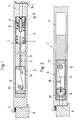
- FIGS. 2 and 3 Another embodiment of the door closer according to the invention is shown in FIGS. 2 and 3.
- the drum unit 5 is introduced into the upper narrow side 3 of the door leaf 1, while the spring unit 4 is arranged in the inner narrow side 6.
- the rotary part 12 is fastened on the closer shaft 13 within the drum unit 5.
- the traction means 11 is wound on the rotating part 12. Starting from the rotating part 12, the traction means 11 runs horizontally in the direction of the inner narrow side 6 and is deflected in the vertical direction after deflection on a deflection roller 19 via a deflection roller 20. In this case, a channel 21 is introduced into the inner narrow side 6 of the door leaf 1 as a connection to the spring unit 4.
- the spring unit 4 is arranged in the lowest region of the door leaf 1.
- the functioning of the spring unit 4 corresponds to that of the exemplary embodiment described with reference to FIG. 1.
- the biasing force of the spiral spring 8 on the sliding part 10 by turning the adjusting screw 16 on which one of the coil spring 8 loaded threaded washer 17 is set.
- the adjusting screw 15 is accessible through a hole 18 in the lower narrow side of the door. The closing force of the door can be adjusted by changing the pretensioning force.
Abstract
Description
Die Erfindung betrifft einen Türschließer mit einem in einer Führung geführten Gleitteil, das von einem Federmittel beaufschlagt ist und das über ein Zugteil mit einer Schließerwelle verbunden und zumindest teilweise auf einem auf der Schließerwelle angebrachten Drehteil aufwickelbar ist.The invention relates to a door closer with a sliding part guided in a guide, which is acted upon by spring means and which is connected to a closer shaft via a pulling part and can at least partially be wound on a rotary part attached to the closer shaft.
Es sind sogenannte Obentürschließer bekannt, die am oberen Rand des Türblattes oder am oberen Rahmenteil der Türzarge befestigt sind. Dabei überträgt ein Gestänge, das als Scherengestänge oder als Gleitarmgestänge ausgebildet sein kann und das zwischen der Zarge und dem Türblatt angeordnet ist, die Kräfte zum Schließen der Tür.So-called overhead door closers are known, which are attached to the upper edge of the door leaf or to the upper frame part of the door frame. A linkage, which can be designed as a scissor linkage or as a sliding arm linkage and which is arranged between the frame and the door leaf, transmits the forces for closing the door.
Ein derartiger Obentürschließer ist beispielsweise aus DE 36 38 353 bekannt. Er weist einen in einem Gehäuse geführten Kolben auf, der von einer Feder beaufschlagt und über ein Getriebe mit der Schließerwelle, an der das Gestänge angebracht ist, verbunden ist. Die Kraftübertragung zwischen Kolben und Getriebe findet mittels eines Hebels statt. Weiterhin ist beispielsweise aus US 2 528 904 ein Türschließer bekannt, der statt des Hebels ein Zugteil zur Kraftübertragung benutzt. Allen derartigen Türschließer ist gemeinsam, daß sie zum einen den Schließvorgang bewirken und dabei gleichzeitig die Bewegung des Türflügels dämpfen. Dabei ist die Dämpfung dadurch gewährleistet, daß sich der Kolben in Hydrauliköl bewegt, das über enge Verbindungskanäle vom Druckraum in den Rückholraum geführt wird.Such an overhead door closer is known for example from DE 36 38 353. It has a piston which is guided in a housing and is loaded by a spring and is connected via a gear to the closer shaft to which the linkage is attached. The power transmission between the piston and the transmission takes place by means of a lever. Furthermore, for example from US 2,528,904 a door closer is known which uses a pulling part for power transmission instead of the lever. All such door closers have in common that on the one hand they effect the closing process and at the same time dampen the movement of the door leaf. The damping is ensured by the fact that the piston is in hydraulic oil moves, which is led from the pressure chamber into the return chamber via narrow connecting channels.
Dadurch daß die Schließerwelle und die Federeinheit, die als Energiespeicher dient, zusammen mit der Dämpfung in einer gemeinsamen Funktionseinheit zusammengefaßt sind, ist die Baugröße des Türschließers zu groß, als daß er bequem in das Blatt einer Tür eingebracht werden kann. Außerdem ist nachteilig, daß die Funktionseinheit an der oberen Schmalseite des Türblattes angeordnet sein muß, da das oben am Türzargen angeordnete Gestänge mit der Schließerwelle zu verbinden ist. Dabei ist insbesondere die Anbringung der Hydraulikeinheit an der oberen Schmalseite des Türblattes nachteilig, da dieser Bereich im Falle eines Brandes wegen der sich nach oben ausbreitenden Hitze besonders heiß wird. Dadurch wird die Funktion der Hydraulikeinheit gerade in der Situation beeinträchtigt, wenn diese ein ordnungsgemäßes Schließen der Tür bewirken sollte. Der Einsatz eines solchen Türschließers bei einer Feuerschutztür ist demnach äußerst problematisch.Characterized in that the closer shaft and the spring unit, which serves as an energy store, together with the damping are combined in a common functional unit, the size of the door closer is too large for it to be conveniently inserted into the leaf of a door. It is also disadvantageous that the functional unit must be arranged on the upper narrow side of the door leaf, since the linkage arranged at the top of the door frame is to be connected to the closer shaft. The attachment of the hydraulic unit on the upper narrow side of the door leaf is particularly disadvantageous since this area becomes particularly hot in the event of a fire due to the heat spreading upwards. As a result, the function of the hydraulic unit is impaired in the situation when it should cause the door to close properly. The use of such a door closer for a fire door is therefore extremely problematic.
Desweiteren ist gerade bei Türschließern, die in das Türblatt eingebracht sind nachteilig, daß diese nur von der zur Drehachse der Tür gerichteten Schmalseite, im Folgenden "innere Schmalseite" genannt zugänglich sind. Um mit einem Werkzeug die Vorspannung der Federkraft zu verstellen ist es meist notwendig, den Türschließer auszubauen oder ein kostspieliges Umlenkgetriebe einzusetzen.Furthermore, it is disadvantageous in the case of door closers which are introduced into the door leaf that they are only accessible from the narrow side directed towards the axis of rotation of the door, hereinafter referred to as the “inner narrow side”. In order to adjust the preload of the spring force with a tool, it is usually necessary to remove the door closer or to use an expensive reversing gear.
Aufgabe der Erfindung ist es einen Türschließer zu schaffen, dessen als Energiespeicher dienende Federeinheit an beliebiger Stelle im Türblatt eingebaut werden kann und der eine hohe Betriebssicherheit bietet.The object of the invention is to provide a door closer, the spring unit serving as an energy store can be installed anywhere in the door leaf and which offers high operational reliability.
Diese Aufgabe wird erfindungsgemäß durch einen Türschließer nach Anspruch 1 gelöst.This object is achieved by a door closer according to
Besondere Ausführungsformen des erfindungsgemäßen Türschließers sind in den Unteransprüchen aufgeführt.Particular embodiments of the door closer according to the invention are listed in the subclaims.
Es ist besonders vorteilhaft, daß der erfindungsgemäße Türschließers getrennt von der Dämpfungseinrichtung angebracht werden kann. Da im Energiespeicher keine hydraulischen Komponenten notwendig sind, läßt er sich besonders kompakt bauen und dabei als kleines Aggregat innerhalb des Türblattes anordnen. Dabei ist es besonders vorteilhaft, daß der Einbauraum des Türschließers vergleichsweise klein ist und die Tür dadurch im oberen Bereich wenigen empfindlich auf die Hizebelastung reagiert und sich weniger stark verzieht.It is particularly advantageous that the door closer according to the invention can be attached separately from the damping device. Since no hydraulic components are required in the energy store, it can be built particularly compactly and arranged as a small unit within the door leaf. It is particularly advantageous that the installation space of the door closer is comparatively small and that the upper part of the door is therefore less sensitive to the heating load and warps less.
Dabei ist desweiteren vorteilhaft, daß der Türschließer eine separate Federeinheit mit einem Raum aufweist, in dem ein Federelement insbesondere in Form einer Spiralfeder angeordnet ist, die ein in dem Raum vorteilhafterweise von einer Schiene geführtes Gleitteil beaufschlagt. An dem Gleitteil ist ein Zugmittel befestigt, das die Federkraft zu einer Trommeleinheit überträgt.It is also advantageous that the door closer has a separate spring unit with a space in which a spring element is arranged, in particular in the form of a spiral spring, which acts on a sliding part advantageously guided in the space by a rail. A traction device is attached to the sliding part, which transmits the spring force to a drum unit.
Die Trommeleinheit weist ein Drehteil auf, das mit der Schließerwelle verbunden ist und auf dem das Zugmittel aufwickelbar ist. Durch die Trennung von Federeinheit und Trommeleinheit ist einerseits eine beliebige Anordnung der Federeinheit möglich. Andererseits können die einzelnen Einheiten so kompakt gebaut werden, daß sie bequem im Türblatt untergebracht werden können. Die Federeinheit ist mit der Trommeleinheit über ein beliebig zu verlegendes Zugteil verbunden.The drum unit has a rotating part which is connected to the closer shaft and on which the traction means can be wound up. By separating the spring unit and drum unit, any arrangement of the spring unit is possible on the one hand. On the other hand, the individual units can be built so compact that they can be conveniently accommodated in the door leaf. The spring unit is connected to the drum unit via an arbitrary tension member.
Vorteilhafterweise sind die Federeinheit und die Trommeleinheit in separate Gehäuse eingebaut, die jeweils in eine gesonderte Ausnehmung im Türblatt einbaubar sind.The spring unit and the drum unit are advantageously installed in separate housings which can each be installed in a separate recess in the door leaf.
Während die Trommeleinheit wegen der durch die mit dem Gestänge verbundene Schließerwelle auf der oberen Schmalseite der Tür im Bereich der inneren Schmalseite angeordnet werden muß, kann die Federeinheit in die obere Schmalseite nahe der das Schloß aufweisenden und der inneren Schmalseite gegenüberliegenden "äußeren Schmalseite" eingebaut werden. Ein derartiger Einbau ist vorteilhaft, da die Federspannung über eine von der äußeren Schmalseite leicht zugängliche Schraube erfolgen kann. Die Übertragung der Federkraft erfolgt dabei mit dem Zugmittel, das insbesondere als Seil oder Band ausgebildet ist. Das Zugmittel kann über Ablenkrollen vertikal abgelenkt und so ausgerichtet werden, daß es ungestört in einer im Türblatt vorgesehenen kanalförmige Ausnehmung in der oberen Schmalseite verläuft.While the drum unit has to be arranged on the upper narrow side of the door in the area of the inner narrow side due to the closer shaft connected to the linkage, the spring unit can be installed in the upper narrow side near the "outer narrow side" which has the lock and is opposite the inner narrow side . Such an installation is advantageous because the spring tension can be done via a screw easily accessible from the outer narrow side. The spring force is transmitted with the traction means, which is designed in particular as a rope or belt. The traction means can be deflected vertically via deflection rollers and aligned in such a way that it runs undisturbed in a channel-shaped recess provided in the door leaf in the upper narrow side.
In einer anderen Ausführungsform des Türschließers ist die Federeinheit in die innere Schmalseite des Türblattes eingebaut. Dabei ist es besonders vorteilhaft, wenn die Federeinheit möglichst tief angeordnet ist. Ein solcher tiefer Einbau gewährleistet, daß sich die Federeinheit im Falle eines Brandes an der kältesten Stelle im Türblatt befindet. Die Federkraft kann über das Zugmittel, in diesem Falle vorteilhafterweise ein Stahlseil, entlang der inneren Schmalseite zur oberen Schmalseite und dort über eine Umlenkrolle in die Ebene der oberen Schmalseite zur Trommeleinheit abgelenkt werden.In another embodiment of the door closer, the spring unit is built into the inner narrow side of the door leaf. It is particularly advantageous if the spring unit is arranged as deep as possible. Such a deep installation ensures that the spring unit is at the coldest point in the door leaf in the event of a fire. The spring force can be deflected via the traction means, in this case advantageously a steel cable, along the inner narrow side to the upper narrow side and there via a deflection roller into the plane of the upper narrow side to the drum unit.
Durch die Trennung der Bauteile ist es möglich, die getrennt einzubauende besonders hitzeempfindliche Dämpfungseinrichtung, die mit Öl gefüllt sein kann, dort zu installieren, wo die Hitzeeinwirkung gering ist. Es kann jedoch vorteilhaft sein, statt der hydraulischen eine mechanische Dämpfungseinrichtung in Verbindung mit dem Türschließer einzusetzen.By separating the components, it is possible to install the separately heat-sensitive damping device, which can be filled with oil, where the heat exposure is low. However, it may be advantageous to use a mechanical damping device in conjunction with the door closer instead of the hydraulic one.
Die insgesamt sehr einfache Konstruktion trägt dazu bei, daß der erfindungsgemäßen Türschließers kostengünstig produziert werden kann. Durch das Fehlen der anfälligen hydraulischen Dämpfungseinheit ist eine hohe Betriebssicherheit gewährleistet.The overall very simple construction contributes to the fact that the door closer according to the invention can be produced inexpensively. The absence of the susceptible hydraulic damping unit ensures high operational reliability.
Um den Begehungskomfort der Tür zu erhöhen ist es vorteilhaft, das auf der Schließerwelle angeordnete Drehteil derart auszubilden, daß der Hebelarm an dem das Zugteil angreift über den Radius variiert. Dazu ist es günstig, wenn der Radius über der entsprechenden Sektor kontinuierlich abnimmt oder wenn das Drehteil exzentrisch gelagert ist. Dadurch kann der gewünschte Momentenverlauf bei einfach herzustellenden Bauteilen erreicht, und die Funktionsparameter verbessert werden. Das Zugteil ist dabei vorteilhafterweise lediglich bis zu maximal einer halben Umdrehung auf dem Drehteil aufwickelbar.In order to increase the ease of access to the door, it is advantageous to design the rotating part arranged on the closer shaft in such a way that the lever arm on which the pulling part acts varies over the radius. To do this, it is convenient if the radius is above the corresponding sector decreases continuously or if the rotating part is eccentrically mounted. As a result, the desired torque curve can be achieved with components that are easy to manufacture, and the functional parameters can be improved. The pulling part can advantageously only be wound up to a maximum of half a turn on the rotating part.
Als Federmittel dient eine Schraubenfeder, die auf Druck belastet wird. Es können jedoch auch andere Federmittel, z.B. Teller- oder Gasfedern oder auf Zug belastete Federn, sowie mehrere gleiche oder verschiedene Federelemente zusammen verwendet werden. Durch die Verwendung mehrerer Federelemente kann die Kraft während des Schließvorganges beliebig variiert werden.A coil spring serves as spring means and is loaded under pressure. However, other spring means, e.g. Disc or gas springs or springs under tension as well as several identical or different spring elements can be used together. By using several spring elements, the force can be varied as required during the closing process.
Besonders vorteilhaft ist es, wenn das Zugteil aus hochfestem biegeelastischen Federband besteht. Ein solches Zugteil ist bei sehr hoher Zugsteifigkeit auf sehr kleine Radien aufwickelbar und zeichnet sich durch hohe Festigkeitswerte aus. Vor der Ablenkung eines solchen Federbandes aus der Ausbreitungsebene heraus ist jedoch eine Torsion um 90° nötig.It is particularly advantageous if the pulling part consists of high-strength, flexible elastic spring band. Such a tensile part can be wound up to very small radii with very high rigidity and is characterized by high strength values. Before such a spring band is deflected out of the plane of propagation, however, a torsion of 90 ° is necessary.
Besondere Ausführungsformen des erfindungsgemäßen Türschließers werden im folgenden anhand der Zeichnungen beschrieben.Particular embodiments of the door closer according to the invention are described below with reference to the drawings.
Es zeigen
Figur 1- einen Türschließer bei dem die Trommeleinheit und die Federeinheit in der oberen Schmalseite eines Türblattes eingebaut sind,
Figur 2- einen Türschließer in Draufsicht, bei dem die Trommeleinheit in der oberen und die Federeinheit in der unteren Schmalseite des Türblattes eingebaut ist und
Figur 3- einen Türschließer in Seitenansicht, bei dem die Trommeleinheit in der oberen und die Federeinheit in der unteren Schmalseite des Türblattes eingebaut ist.
- Figure 1
- a door closer in which the drum unit and the spring unit are installed in the upper narrow side of a door leaf,
- Figure 2
- a door closer in plan view, in which the drum unit is installed in the upper and the spring unit in the lower narrow side of the door leaf and
- Figure 3
- a door closer in side view, in which the drum unit is installed in the upper and the spring unit in the lower narrow side of the door leaf.
Figur 1 zeigt eine Draufsicht auf ein Türblatt 1 das im Türzargen an Scharnieren 2 drehbar aufgehängt ist. In die obere Schmalseite 3 des Türblattes sind eine Federeinheit 4 und eine Trommeleinheit 5 in getrennte Ausnehmungen im Türblatt 1 eingebracht. Dabei ist die Trommeleinheit 5 nahe der den Scharnieren 2 zugeordneten Seite des Türblattes 1, im folgenden als "innere Schmalseite" 6 bezeichnet, angeordnet, während die Federeinheit 4 auf der anderen in den Falz des Türzargens eingreifenden Seite im folgenden als "äußere Schmalseite" 7 bezeichnet", angeordnet ist. Federeinheit 4 und Trommeleinheit 5 sind über ein kraftübertragendes Zugmittel 11 verbunden.Figure 1 shows a plan view of a
Die Federeinheit 4 weist einen Raum auf, in dem ein Federelement insbesondere in Form einer Spiralfeder 8 angeordnet ist. In diesem Ausführungsbeispiel ist die Federeinheit 4 von einem Gehäuse 9 umgeben, das als Führung für ein darin verschieblich angeordnetes Gleitteil 10 dient. Über das Gleitteil 10 wird die Spiralfeder 8, die in die Schließstellung der Tür vorgespannt ist, mit einer Kraft beaufschlagt, bzw. beaufschlagt die zusammengedrückte Spiralfeder 8 das Gleitteil 10. An dem Gleitteil 10 ist ein Zugmittel 11 insbesondere ein Federband oder ein Stahlseil befestigt, das die Federkraft zu der Trommeleinheit 5 überträgt.The
Die Trommeleinheit 5 weist ein Drehteil 12 auf, das mit der Schließerwelle 13 verbunden und auf dem das Zugmittel 11 aufwickelbar ist. In diesem Ausführungsbeispiel ist das Drehteil 12 auf der Schließerwelle 13 befestigt. Beim Öffnen der Tür wird das Drehteil 12 mittels eines nicht dargestellten Gestänges um einen bestimmten Sektor gedreht. Durch das Drehen wird das tangential am Drehteil 12 befestigte Zugmittel 11 aufgewickelt. Dabei wird die Kraft über das Zugmittel 11, das zunächst an einer Ablenkrolle 14 in horizontaler Richtung abgelenkt wird, zum Gleitteil 10 übertragen. Das Zugmittel 11 ist dabei durch eine Ausnehmung insbesondere einen Kanal 15, der in die obere Schmalseite des Türblattes 1 eingelassen ist, geführt. Der Kanal 15 verbindet die Federeinheit 4 mit der Trommeleinheit 5. Die Ablenkrolle 14 dient dazu, das Zugmittel 11 so auszurichten, daß eine Führung parallel zu den Kanten des Türblattes gewährleistet ist. Dabei wird es aus der axialen Richtung zum Gleitteil 10 in Richtung tangential zum Drehteil 12 abgelenkt.The
Die Vorspannkraft der Spiralfeder 8 auf das Gleitteil 10 ist durch Verdrehen einer Einstellschraube 16, die durch eine Bohrung 18 in der äußeren Schmalseite 7 der Tür zugänglich ist und auf der sich eine von der Spiralfeder 8 beaufschlagte Gewindescheibe 17 befindet, einstellbar.The biasing force of the
Eine andere Ausführungsform des erfindungsgemäßen Türschließers ist in den Figuren 2 und 3 dargestellt. Dabei ist lediglich die Trommeleinheit 5 in die obere Schmalseite 3 des Türblattes 1 eingebracht, während die Federeinheit 4 in der inneren Schmalseite 6 angeordnet ist. Innerhalb der Trommeleinheit 5 ist das Drehteil 12 auf der Schließerwelle 13 befestigt. Auf das Drehteil 12 ist das Zugmittel 11 aufgewickelt. Das Zugmittel 11 verläuft von dem Drehteil 12 ausgehend horizontal in Richtung der inneren Schmalseite 6 und wird nach einer Ablenkung an einer Ablenkrolle 19 über eine Umlenkrolle 20 in vertikale Richtung umgelenkt. Dabei ist in die innere Schmalseite 6 des Türblattes 1 ein Kanal 21 als Verbindung zur Federeinheit 4 eingebracht.Another embodiment of the door closer according to the invention is shown in FIGS. 2 and 3. In this case, only the
Die Federeinheit 4 ist in diesem Ausführungsbeispiel im untersten Bereich des Türblattes 1 angeordnet. Die Funktionsweise der Federeinheit 4 entspricht der des anhand Figur 1 beschriebenen Ausführungsbeispieles. Dabei kann die Vorspannkraft der Spiralfeder 8 auf das Gleitteil 10 durch Verdrehen der Einstellschraube 16, auf der sich eine von der Spiralfeder 8 beaufschlagte Gewindescheibe 17 befindet, eingestellt werden. Die Einstellschraube 15 ist durch eine Bohrung 18 in der unteren Schmalseite der Tür zugänglich. Durch Änderung der Vorspannkraft ist die Schließkraft der Tür einstellbar.In this exemplary embodiment, the
Claims (13)
dadurch gekennzeichnet, daß das Gleitteil (10) und das Federmittel (8) in einer Federeinheit (4) zusammengefaßt sind, die von einer das Drehteil (12) beinhaltenden Trommeleinheit (5) getrennt im Türblatt (1) angeordnet und über das Zugteil (11) mit der Trommeleinheit (5) verbunden ist.Door closer with a sliding part (10) guided in a guide, which is acted upon by spring means (8) and which is connected to a closer shaft (13) via a pull part (11) and at least partially on a rotating part (13) attached to the closer shaft (13) 12) can be wound up,
characterized in that the sliding part (10) and the spring means (8) are combined in a spring unit (4) which is arranged separately from a drum unit (5) containing the rotating part (12) in the door leaf (1) and via the pulling part (11 ) is connected to the drum unit (5).
dadurch gekennzeichnet, daß zwischen dem Gleitteil (10) und dem Drehteil (12) eine Ablenkeinrichtung insbesondere eine Rolle (5) angeordnet ist, mit der das Zugteil (11) aus der axialen Richtung zum Gleitteil (10) in die tangentiale Richtung zum Drehteil (12) ablenkbar ist.Door closer according to claim 1,
characterized in that a deflection device, in particular a roller (5), is arranged between the sliding part (10) and the rotating part (12), with which the pulling part (11) from the axial direction to the sliding part (10) in the tangential direction to the rotating part ( 12) is distractible.
dadurch gekennzeichnet, daß das Zugteil (11) von einem horizontalen Verlauf über eine Umlenkrolle (20) in einen vertikalen Verlauf umgelenkbar ist.Door closer according to claim 1 or 2,
characterized in that the pulling part (11) can be deflected from a horizontal course via a deflection roller (20) into a vertical course.
dadurch gekennzeichnet, daß das Zugteil (11) in einer Ausnehmung insbesondere einem Kanal (15) geführt ist, der im Türblatt (1) verläuft und die Trommeleinheit (5) mit der Federeinheit (4) verbindet.Door closer according to one of the preceding claims,
characterized in that the pulling part (11) is guided in a recess, in particular a channel (15) which runs in the door leaf (1) and connects the drum unit (5) to the spring unit (4).
dadurch gekennzeichnet, daß die Trommeleinheit (5) und die Federeinheit (4) in der oberen Schmalseite (3) des Türblattes (1) eingebracht sind.Door closer according to one of the preceding claims,
characterized in that the drum unit (5) and the spring unit (4) are introduced into the upper narrow side (3) of the door leaf (1).
dadurch gekennzeichnet, daß der Kanal in der oberen Schmalseite (3) des Türblattes (1) eingebracht ist.Door closer according to claim 5,
characterized in that the channel is introduced in the upper narrow side (3) of the door leaf (1).
dadurch gekennzeichnet, daß die Federeinheit (4) in unmittelbarer Nähe der äußeren Schmalseite (7) des Türblattes (1) eingebracht ist.Door closer according to claim 5,
characterized in that the spring unit (4) is introduced in the immediate vicinity of the outer narrow side (7) of the door leaf (1).
dadurch gekennzeichnet, daß die Trommeleinheit (5) in der oberen Schmalseite (3) und die Federeinheit (4) in der die Scharniere (2) tragende innere Schmalseite (6) des Türblattes (1) eingebracht ist.Door closer according to one of the preceding claims,
characterized in that the drum unit (5) is introduced in the upper narrow side (3) and the spring unit (4) in the inner narrow side (6) of the door leaf (1) which carries the hinges (2).
dadurch gekennzeichnet, daß der Kanal (21) in der inneren Schmalseite (6) des Türblattes (1) eingebracht ist.Door closer according to claim 8,
characterized in that the channel (21) is introduced in the inner narrow side (6) of the door leaf (1).
dadurch gekennzeichnet, daß die Federeinheit (4) in die innere Schmalseite (6) im unteren Bereich des Türblattes (1) eingebracht ist.Door closer according to claim 8,
characterized in that the spring unit (4) is introduced into the inner narrow side (6) in the lower region of the door leaf (1).
dadurch gekennzeichnet, daß das Drehteil (12) auf dem Sektor, auf dem das Zugteil (11) aufwickelbar ist, unterschiedlich lange wirksame Hebelarme aufweist.Door closer according to one of the preceding claims,
characterized in that the rotating part (12) has lever arms of different lengths on the sector on which the pulling part (11) can be wound.
dadurch gekennzeichnet, daß das Drehteil (12) fest mit der Schließerwelle (13) verbunden ist.Door closer according to one of the preceding claims,
characterized in that the rotating part (12) is fixedly connected to the closer shaft (13).
dadurch gekennzeichnet, daß an dem Drehteil (12) ein Schwenkarm befestigt ist, der die Bewegung des Türflügels (1) auf eine Dämpfungseinrichtung überträgt, die außerhalb des Türflügels (1) und/oder des Gehäuses (9) der Federeinheit (4) angebracht istDoor closer according to one of the preceding claims,
characterized in that a pivot arm is attached to the rotating part (12), which transmits the movement of the door leaf (1) to a damping device which is attached outside the door leaf (1) and / or the housing (9) of the spring unit (4)
Applications Claiming Priority (2)
| Application Number | Priority Date | Filing Date | Title |
|---|---|---|---|
| DE19620382 | 1996-05-21 | ||
| DE19620382A DE19620382A1 (en) | 1996-05-21 | 1996-05-21 | Door closer |
Publications (1)
| Publication Number | Publication Date |
|---|---|
| EP0808983A1 true EP0808983A1 (en) | 1997-11-26 |
Family
ID=7794868
Family Applications (1)
| Application Number | Title | Priority Date | Filing Date |
|---|---|---|---|
| EP97108019A Withdrawn EP0808983A1 (en) | 1996-05-21 | 1997-05-16 | Door closer |
Country Status (2)
| Country | Link |
|---|---|
| EP (1) | EP0808983A1 (en) |
| DE (1) | DE19620382A1 (en) |
Cited By (2)
| Publication number | Priority date | Publication date | Assignee | Title |
|---|---|---|---|---|
| US6345412B1 (en) | 1997-06-27 | 2002-02-12 | Ingersoll-Rand Architectural Hardware Group Ltd. | Arrangement for controlling an angularly movable member |
| US8225458B1 (en) | 2001-07-13 | 2012-07-24 | Hoffberg Steven M | Intelligent door restraint |
Families Citing this family (1)
| Publication number | Priority date | Publication date | Assignee | Title |
|---|---|---|---|---|
| DE19831393B4 (en) | 1998-07-14 | 2016-12-08 | Ernst Schulte | door closers |
Citations (2)
| Publication number | Priority date | Publication date | Assignee | Title |
|---|---|---|---|---|
| US1730948A (en) * | 1928-07-17 | 1929-10-08 | Condor Company | Door closer |
| US2528904A (en) * | 1945-03-09 | 1950-11-07 | Norballe Svend Gunge | Closing device for doors |
Family Cites Families (7)
| Publication number | Priority date | Publication date | Assignee | Title |
|---|---|---|---|---|
| DE239812C (en) * | ||||
| US1343033A (en) * | 1919-05-24 | 1920-06-08 | Campbell John Alpheus | Door-spring |
| US1942185A (en) * | 1930-07-01 | 1934-01-02 | Yale & Towne Mfg Co | Door closer |
| US2295496A (en) * | 1941-05-27 | 1942-09-08 | James L Cameron | Storm door protecting and closing mechanism |
| US4665584A (en) * | 1985-05-29 | 1987-05-19 | Williams Patrick Y | Buoyant valve member closing device for doors |
| DE3638353C3 (en) * | 1985-07-05 | 1997-06-19 | Geze Grundstueck Beteiligung | Door closer |
| US5535488A (en) * | 1995-02-22 | 1996-07-16 | China Textile Institute | Carding and drawing system for spinning process |
-
1996
- 1996-05-21 DE DE19620382A patent/DE19620382A1/en not_active Withdrawn
-
1997
- 1997-05-16 EP EP97108019A patent/EP0808983A1/en not_active Withdrawn
Patent Citations (2)
| Publication number | Priority date | Publication date | Assignee | Title |
|---|---|---|---|---|
| US1730948A (en) * | 1928-07-17 | 1929-10-08 | Condor Company | Door closer |
| US2528904A (en) * | 1945-03-09 | 1950-11-07 | Norballe Svend Gunge | Closing device for doors |
Cited By (4)
| Publication number | Priority date | Publication date | Assignee | Title |
|---|---|---|---|---|
| US6345412B1 (en) | 1997-06-27 | 2002-02-12 | Ingersoll-Rand Architectural Hardware Group Ltd. | Arrangement for controlling an angularly movable member |
| US8225458B1 (en) | 2001-07-13 | 2012-07-24 | Hoffberg Steven M | Intelligent door restraint |
| US9121217B1 (en) | 2001-07-13 | 2015-09-01 | Steven M. Hoffberg | Intelligent door restraint |
| US9995076B1 (en) | 2001-07-13 | 2018-06-12 | Steven M. Hoffberg | Intelligent door restraint |
Also Published As
| Publication number | Publication date |
|---|---|
| DE19620382A1 (en) | 1997-11-27 |
Similar Documents
| Publication | Publication Date | Title |
|---|---|---|
| DE19506220C2 (en) | Door closer | |
| EP0141902B1 (en) | Device for controlling the closure sequence of double doors | |
| EP1828522B1 (en) | Door drive mechanism, especially revolving door drive mechanism | |
| DE4038720C2 (en) | Upper door closer with slide rail linkage | |
| EP2122097B1 (en) | Drive for the door leaf of a conventional door | |
| EP1870552B1 (en) | Device for regulating the closing sequence for swinging doors with two wings | |
| EP2725176A2 (en) | Door closer | |
| WO2000042282A1 (en) | Drive | |
| DE19901033C2 (en) | Swing door drive | |
| DE19545401A1 (en) | Closing sequence control for automatically closing double-panel door | |
| DE2535244B2 (en) | UNIVERSAL LOCKER | |
| DE102004061621A1 (en) | Door drive, in particular swing door drive | |
| EP0622574A2 (en) | Actuating device for a rotatable valve shut-off element | |
| WO2006066667A1 (en) | Door drive, in particular a revolving door drive | |
| DE102004061628A1 (en) | Door drive, in particular swing door drive | |
| DE2649629C2 (en) | Drive with accident prevention device for gates or the like | |
| DE10031403C2 (en) | Overhead door closer with a slide rail arrangement | |
| EP0808983A1 (en) | Door closer | |
| EP0324075A1 (en) | Device for controlling the closure sequence of double-wing doors | |
| EP1870553B1 (en) | Device for regulating the order of closing for rotary doors with two leafs | |
| EP1870551A2 (en) | Device for regulating the closing sequence for swinging doors with two leaves | |
| EP1870550B1 (en) | Device for controlling the closing sequence of rotary doors with two leaves | |
| DE19532262B4 (en) | Device for closing sequence control for double-leaf doors | |
| EP1247931B1 (en) | Closure sequence controller | |
| DE3104568A1 (en) | Device for closing of doors and gates, especially sliding gates |
Legal Events
| Date | Code | Title | Description |
|---|---|---|---|
| PUAI | Public reference made under article 153(3) epc to a published international application that has entered the european phase |
Free format text: ORIGINAL CODE: 0009012 |
|
| AK | Designated contracting states |
Kind code of ref document: A1 Designated state(s): AT BE CH DE DK ES FR GB GR IT LI NL SE |
|
| 17P | Request for examination filed |
Effective date: 19980409 |
|
| GRAG | Despatch of communication of intention to grant |
Free format text: ORIGINAL CODE: EPIDOS AGRA |
|
| GRAG | Despatch of communication of intention to grant |
Free format text: ORIGINAL CODE: EPIDOS AGRA |
|
| GRAH | Despatch of communication of intention to grant a patent |
Free format text: ORIGINAL CODE: EPIDOS IGRA |
|
| 17Q | First examination report despatched |
Effective date: 19980803 |
|
| GRAH | Despatch of communication of intention to grant a patent |
Free format text: ORIGINAL CODE: EPIDOS IGRA |
|
| STAA | Information on the status of an ep patent application or granted ep patent |
Free format text: STATUS: THE APPLICATION IS DEEMED TO BE WITHDRAWN |
|
| 18D | Application deemed to be withdrawn |
Effective date: 19991201 |