EP0806930B1 - Head rest assembly for spas and whirlpools - Google Patents
Head rest assembly for spas and whirlpools Download PDFInfo
- Publication number
- EP0806930B1 EP0806930B1 EP96906168A EP96906168A EP0806930B1 EP 0806930 B1 EP0806930 B1 EP 0806930B1 EP 96906168 A EP96906168 A EP 96906168A EP 96906168 A EP96906168 A EP 96906168A EP 0806930 B1 EP0806930 B1 EP 0806930B1
- Authority
- EP
- European Patent Office
- Prior art keywords
- head rest
- rest assembly
- nozzle
- pillow
- body member
- Prior art date
- Legal status (The legal status is an assumption and is not a legal conclusion. Google has not performed a legal analysis and makes no representation as to the accuracy of the status listed.)
- Expired - Lifetime
Links
Images


Classifications
-
- A—HUMAN NECESSITIES
- A61—MEDICAL OR VETERINARY SCIENCE; HYGIENE
- A61H—PHYSICAL THERAPY APPARATUS, e.g. DEVICES FOR LOCATING OR STIMULATING REFLEX POINTS IN THE BODY; ARTIFICIAL RESPIRATION; MASSAGE; BATHING DEVICES FOR SPECIAL THERAPEUTIC OR HYGIENIC PURPOSES OR SPECIFIC PARTS OF THE BODY
- A61H23/00—Percussion or vibration massage, e.g. using supersonic vibration; Suction-vibration massage; Massage with moving diaphragms
- A61H23/04—Percussion or vibration massage, e.g. using supersonic vibration; Suction-vibration massage; Massage with moving diaphragms with hydraulic or pneumatic drive
-
- A—HUMAN NECESSITIES
- A61—MEDICAL OR VETERINARY SCIENCE; HYGIENE
- A61H—PHYSICAL THERAPY APPARATUS, e.g. DEVICES FOR LOCATING OR STIMULATING REFLEX POINTS IN THE BODY; ARTIFICIAL RESPIRATION; MASSAGE; BATHING DEVICES FOR SPECIAL THERAPEUTIC OR HYGIENIC PURPOSES OR SPECIFIC PARTS OF THE BODY
- A61H33/00—Bathing devices for special therapeutic or hygienic purposes
- A61H33/60—Components specifically designed for the therapeutic baths of groups A61H33/00
- A61H33/601—Inlet to the bath
- A61H33/6021—Nozzles
- A61H33/6063—Specifically adapted for fitting in bathtub walls
-
- A—HUMAN NECESSITIES
- A61—MEDICAL OR VETERINARY SCIENCE; HYGIENE
- A61H—PHYSICAL THERAPY APPARATUS, e.g. DEVICES FOR LOCATING OR STIMULATING REFLEX POINTS IN THE BODY; ARTIFICIAL RESPIRATION; MASSAGE; BATHING DEVICES FOR SPECIAL THERAPEUTIC OR HYGIENIC PURPOSES OR SPECIFIC PARTS OF THE BODY
- A61H2201/00—Characteristics of apparatus not provided for in the preceding codes
- A61H2201/12—Driving means
- A61H2201/1207—Driving means with electric or magnetic drive
-
- A—HUMAN NECESSITIES
- A61—MEDICAL OR VETERINARY SCIENCE; HYGIENE
- A61H—PHYSICAL THERAPY APPARATUS, e.g. DEVICES FOR LOCATING OR STIMULATING REFLEX POINTS IN THE BODY; ARTIFICIAL RESPIRATION; MASSAGE; BATHING DEVICES FOR SPECIAL THERAPEUTIC OR HYGIENIC PURPOSES OR SPECIFIC PARTS OF THE BODY
- A61H2201/00—Characteristics of apparatus not provided for in the preceding codes
- A61H2201/16—Physical interface with patient
- A61H2201/1602—Physical interface with patient kind of interface, e.g. head rest, knee support or lumbar support
- A61H2201/1609—Neck
-
- A—HUMAN NECESSITIES
- A61—MEDICAL OR VETERINARY SCIENCE; HYGIENE
- A61H—PHYSICAL THERAPY APPARATUS, e.g. DEVICES FOR LOCATING OR STIMULATING REFLEX POINTS IN THE BODY; ARTIFICIAL RESPIRATION; MASSAGE; BATHING DEVICES FOR SPECIAL THERAPEUTIC OR HYGIENIC PURPOSES OR SPECIFIC PARTS OF THE BODY
- A61H2201/00—Characteristics of apparatus not provided for in the preceding codes
- A61H2201/16—Physical interface with patient
- A61H2201/1602—Physical interface with patient kind of interface, e.g. head rest, knee support or lumbar support
- A61H2201/1654—Layer between the skin and massage elements, e.g. fluid or ball
-
- A—HUMAN NECESSITIES
- A61—MEDICAL OR VETERINARY SCIENCE; HYGIENE
- A61H—PHYSICAL THERAPY APPARATUS, e.g. DEVICES FOR LOCATING OR STIMULATING REFLEX POINTS IN THE BODY; ARTIFICIAL RESPIRATION; MASSAGE; BATHING DEVICES FOR SPECIAL THERAPEUTIC OR HYGIENIC PURPOSES OR SPECIFIC PARTS OF THE BODY
- A61H2201/00—Characteristics of apparatus not provided for in the preceding codes
- A61H2201/50—Control means thereof
- A61H2201/5007—Control means thereof computer controlled
-
- A—HUMAN NECESSITIES
- A61—MEDICAL OR VETERINARY SCIENCE; HYGIENE
- A61H—PHYSICAL THERAPY APPARATUS, e.g. DEVICES FOR LOCATING OR STIMULATING REFLEX POINTS IN THE BODY; ARTIFICIAL RESPIRATION; MASSAGE; BATHING DEVICES FOR SPECIAL THERAPEUTIC OR HYGIENIC PURPOSES OR SPECIFIC PARTS OF THE BODY
- A61H2205/00—Devices for specific parts of the body
- A61H2205/04—Devices for specific parts of the body neck
-
- A—HUMAN NECESSITIES
- A61—MEDICAL OR VETERINARY SCIENCE; HYGIENE
- A61H—PHYSICAL THERAPY APPARATUS, e.g. DEVICES FOR LOCATING OR STIMULATING REFLEX POINTS IN THE BODY; ARTIFICIAL RESPIRATION; MASSAGE; BATHING DEVICES FOR SPECIAL THERAPEUTIC OR HYGIENIC PURPOSES OR SPECIFIC PARTS OF THE BODY
- A61H33/00—Bathing devices for special therapeutic or hygienic purposes
- A61H33/0087—Therapeutic baths with agitated or circulated water
Definitions
- the present invention relates primarily to bathing fixtures such as hydro-massage spas and whirlpools. More particularly, it relates to a head rest member for use with such bathing fixtures.
- US-A-4 860 392 shows the flow of a fluid stream against a flexible material to effect a massaging action as to US-A-4 635 619 and 4 953 240. See also US-A-5 010 605.
- the present invention provides a head rest assembly for use in conjunction with a bathing fixture having pumping means for supplying fluid under pressure to a fluid inlet nozzle, comprising a body member including a section to support a head; the fluid inlet nozzle providing fluid to the body member; a support bracket connected to the body member and the nozzle; and means to indicate when the body member is positioned to cover the nozzle, characterized by said last mentioned means comprising a magnet positioned on the bracket and a reed switch is positioned on the nozzle to signal the proximity of the magnet to allow activation of the pumping means when the body member is positioned to cover the nozzle.
- said last mentioned means comprising a magnet positioned on the bracket and a reed switch is positioned on the nozzle to signal the proximity of the magnet to allow activation of the pumping means when the body member is positioned to cover the nozzle.
- the objects of the invention therefore include:
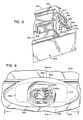
- the head rest assembly is employed in conjunction with a hydro-massage whirlpool, generally 12, which includes a tub 14 having a plurality of conventional whirlpool nozzles 15 projecting through an interior side wall such as 17.
- the tub has the usual floor 18 with a standard drain opening 19.
- a soft cushion 13 is attached to the rim of the tub above end wall 20 with the head rest assembly 10 positioned centrally therein.
- nozzles 21 which are arranged in pairs except for the outer two nozzles 21'.
- the head rest assembly 10 includes a pillow 11 having a generally C-shaped configuration with a central section 24 and two leg sections 26 and 27.
- the pillow is preferably composed of a self-skinning urethane foam and has a fine mesh, fabric cover 16 extending thereover.
- the primary purpose of the fabric cover is to provide a dampening or softening of the force of the water jet stream from nozzles 32 and 33 so that the water will not project beyond the bathing well while allowing water to pass therethrough.
- a drain net 25 is connected to cover 16 for placement between the leg sections 26 and 27 and extending from central section 24. This provides a drainage of the water from the pillow.
- the pillow is preferably molded around a bracket 30 composed of polypropylene.
- the bracket 30 also has a central section 28 and two leg sections 29 and 31 which surround the nozzles 32 and 33. It is attached to the nozzles 32 and 33 in a manner explained later in detail in conjunction with Figs. 9-12.
- the nozzles such as 33 are held in place and connected to the tub wall 20 by the nut 36 and the washer 35 with a threaded connection 37 provided between the nozzle 33 and the nut 36. Water is supplied to the nozzle such as through the usual conduit 57.
- a magnet 50 is housed in the bracket 30 and is utilized to activate a reed switch 45.
- a support surface 38 for the bracket 30 is provided by the nozzle body 43.
- a nozzle cover 44 is connected to nozzle 33 such as by the hooked portion 44' engaging flanged portion 33' of nozzle 33.
- the reed switch 45 is connected to the electrical lines 47 and 48. This permits activation of a pumping apparatus (not shown) when the pillow 11 is in place.
- the nozzles 32 and 33 are joined by a central body section 39 of nozzle body 43 having a living hinge 40 provided by cutout 46.
- the nozzles 32 and 33, as well as the central body section 39, are molded from a semi-rigid plastic material.
- the living hinge 40 allows a hinging action between the two nozzles 32 and 33 so as to facilitate connection to a curved wall of a tub.
- a peripheral groove 49 is provided for connection with the bracket 30.
- Figs. 5-10 show an alternative embodiment. Similar numbers refer to the same or similar components as described with embodiment 10 except they are designated with the suffix "A".
- the major difference between the two embodiments is that embodiment 10A includes a different pillow design having the central concave portions 53A and 54A and an oval shaped body 23A. This is seen in Fig. 7.
- a lip portion 56A which extends from the back of pillow 10A and over the top of the tub 14A. This is utilized to cover the side wall of the tub 14A where it is curved. In many instances, the tub 14A will not have a major curvature and consequently the lip can be eliminated.
- the pillow 11A has a curved wall section 58A to accommodate the upper curved wall 20A of the tub, as well as a lower flat edge portion 55A.
- embodiment 10A does not have the drain net 25 in conjunction with the cover 16A. Drainage is afforded instead by a concave portion 54A extending along the backside of pillow 11A between the leg portions 26A and 27A.
- a pillow in the general shape of a boomerang can be used. It would not have the drain net 25 or concave portion 54. Instead a recessed channel would be present in the back of the pillow which serves the same drainage result.
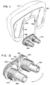
- Figs. 9, 10 and 11 show the attachment of the pillow bracket 30A to the nozzles 32A and 33A.
- a peripheral groove 49A extends around the nozzles 32A and 33A. It receives an inner edge portion 59A of the bracket 30A which terminates in the tabs 41A and 42A and results in the connection shown in Figs. 6 and 8.
- Fig. 12 shows in further detail the living hinge 40A as provided by the cutout 46A in the central section 39A of the nozzle body 43A.
- the pillow 11A is shown as extending from end wall 20A with a portion extending over top rim 22A. It is not used with the cushion 13 shown in Fig. 1. If desired, it can be incorporated into a cushion or another pillow such as 13 with the cushion being cut out to conform to the oval shape of pillow 11A.
- the invention provides an improved head rest member for use in conjunction with a hydro-massage whirlpool.
- a pillow is provided as a head rest member which is easily attached and supported by the neck massage nozzles.
- the pillow can be of various designs to complement the configuration of the wall of the whirlpool. It also has a cover which can be decorated with various aesthetic designs and colors.
- a unique nozzle unit is provided having a living hinge which can accommodate the wall configurations of the whirlpool.
- the attachment of the pillow to the jet nozzles also affords the use of an electrical safety device in conjunction with the magnet and the reed switch so that the jets cannot be activated without placement of the pillow.
- the attachment of the pillow to the jet nozzles and its advantages are accomplished without the use of the magnet and the switch.
- the living hinge aspect of the nozzles has advantages, the pillow connection is also effected without it.
- the pillow can be of various configurations and incorporated in a cushion, or it can also be utilized without it. Certain materials have been utilized in composing different elements of the pillow, the bracket and the nozzle. Obviously, other materials can be advantageously employed.
Landscapes
- Health & Medical Sciences (AREA)
- Public Health (AREA)
- Animal Behavior & Ethology (AREA)
- Physical Education & Sports Medicine (AREA)
- Rehabilitation Therapy (AREA)
- Life Sciences & Earth Sciences (AREA)
- Pain & Pain Management (AREA)
- General Health & Medical Sciences (AREA)
- Epidemiology (AREA)
- Veterinary Medicine (AREA)
- Massaging Devices (AREA)
- Percussion Or Vibration Massage (AREA)
- Devices For Medical Bathing And Washing (AREA)
Description
Claims (11)
- A head rest assembly for use in conjunction with a bathing fixture having pumping means for supplying fluid under pressure to a fluid inlet nozzle, comprising a body member (10,10A) including a section (16,16A) to support a head; the fluid inlet nozzle (32,33; 32A,33A) providing fluid to the body member; a support bracket (30,30A) connected to the body member and the nozzle; and means to indicate when the body member is positioned to cover the nozzle, characterized by said last mentioned means comprising a magnet (50,50A) positioned on the bracket (30,30A) and a reed switch (45,45A) is positioned on the nozzle to signal the proximity of the magnet to allow activation of the pumping means when the body member is positioned to cover the nozzle.
- The head rest assembly as defined in claim 1, characterized in that the body member is a pillow (11,11A).
- The head rest assembly as defined in claim 2, characterized in that the pillow (11,11A) is horseshoe shaped from a frontal view.
- The head rest assembly as defined in claim 2, characterized in that the pillow (11A) has at least one central hollow section (53A) and an opposing concave or grooved surface (54A).
- The head rest assembly as defined in claim 2, characterized in that the pillow (11) is partially surrounded by a cushion (13).
- The head rest assembly as defined in claim 2, characterized in that the pillow (11,11A) is partially surrounded by a cover (16,16A) which allows water to pass therethrough.
- The head rest assembly as defined in claim 1, characterized in that the bracket (30,30A) is connected to the nozzle by an inner portion extending from the bracket for reception in a groove on the nozzle.
- The head rest assembly as defined in claim 1, characterized in that the assembly is mounted on a hydro-massage spa or whirlpool
- The head rest assembly as defined in claim 1, characterized in that the support bracket (30,30A) is partially enclosed in the body member (10,10A).
- The head rest assembly as defined in claim 9, characterized in that the bracket (30,30A) is molded into the body member.
- The head rest assembly as defined in claim 1, characterized in that the body member defines a pillow (11) and includes a central section (24) and two spaced apart enlarged sections (26,27) with the central section adapted to receive the neck and head.
Priority Applications (1)
| Application Number | Priority Date | Filing Date | Title |
|---|---|---|---|
| EP99107117A EP0933076B1 (en) | 1995-01-23 | 1996-01-03 | Head rest assembly for spas and whirlpools |
Applications Claiming Priority (3)
| Application Number | Priority Date | Filing Date | Title |
|---|---|---|---|
| US376575 | 1989-07-07 | ||
| US08/376,575 US5546616A (en) | 1993-08-16 | 1995-01-23 | Head rest assembly |
| PCT/US1996/000540 WO1996022759A1 (en) | 1995-01-23 | 1996-01-03 | Head rest assembly for spas and whirlpools |
Related Child Applications (1)
| Application Number | Title | Priority Date | Filing Date |
|---|---|---|---|
| EP99107117A Division EP0933076B1 (en) | 1995-01-23 | 1996-01-03 | Head rest assembly for spas and whirlpools |
Publications (3)
| Publication Number | Publication Date |
|---|---|
| EP0806930A1 EP0806930A1 (en) | 1997-11-19 |
| EP0806930B1 true EP0806930B1 (en) | 2001-05-16 |
| EP0806930B9 EP0806930B9 (en) | 2002-05-15 |
Family
ID=23485563
Family Applications (2)
| Application Number | Title | Priority Date | Filing Date |
|---|---|---|---|
| EP99107117A Expired - Lifetime EP0933076B1 (en) | 1995-01-23 | 1996-01-03 | Head rest assembly for spas and whirlpools |
| EP96906168A Expired - Lifetime EP0806930B9 (en) | 1995-01-23 | 1996-01-03 | Head rest assembly for spas and whirlpools |
Family Applications Before (1)
| Application Number | Title | Priority Date | Filing Date |
|---|---|---|---|
| EP99107117A Expired - Lifetime EP0933076B1 (en) | 1995-01-23 | 1996-01-03 | Head rest assembly for spas and whirlpools |
Country Status (6)
| Country | Link |
|---|---|
| US (2) | US5546616A (en) |
| EP (2) | EP0933076B1 (en) |
| AU (1) | AU4963696A (en) |
| DE (3) | DE69612837D1 (en) |
| ES (2) | ES2222634T3 (en) |
| WO (1) | WO1996022759A1 (en) |
Families Citing this family (10)
| Publication number | Priority date | Publication date | Assignee | Title |
|---|---|---|---|---|
| US6186964B1 (en) * | 1996-09-27 | 2001-02-13 | Tony J. Branham | Hydro-massage pillow system |
| US6351859B1 (en) | 1997-08-19 | 2002-03-05 | John V. Maiuccoro | Hydrotherapy tub coplanar flow |
| BR9815964A (en) * | 1998-07-27 | 2001-06-05 | Webtv Networks Inc | Remote computer access process, remote computing server system, video transmission process, multi-head monitor generator, processes for generating a compressed video stream, from motion estimation to image stream compression, to change the detection for image stream compression, for generating a catalogue, and for internet browsing, software program for www page design, software modified by compression to perform at least one function and to generate at least one video, control processes of video, image processing, video compression, asynchronous video stream compression, to store frame rate, to customize advertising, advertising, throughput accrual, interactive tv, to allocate bandwidth to a stream of compressed video, for allocating bandwidth for transmitting video over a cable network, for generating a plurality of videos, for transmitting a plurality of similar compressed video channels, statistically bit multiplexing, to generate a plurality of unrelated image streams, to generate a plurality of unrelated audio streams, and to produce different representations of video in a plurality of locations remote |
| US7597652B2 (en) * | 2001-11-28 | 2009-10-06 | Dimension One Spas | Hydrotherapy mounting apparatus and exercise system |
| CA2491782C (en) | 2004-01-06 | 2012-05-22 | C.G. Air Systemes Inc. | Cushion system for a washing/bathing tub |
| US20090089926A1 (en) * | 2007-10-04 | 2009-04-09 | Larsen Christopher C | Spa shell pillow |
| US8141181B2 (en) * | 2007-12-04 | 2012-03-27 | Aquatic Co. | Neck jet pillow for whirlpool tub or spa |
| US7996932B2 (en) * | 2008-03-28 | 2011-08-16 | Elnar Joseph G | Spa wall mounted water jet neck and shoulder massager |
| US11304872B2 (en) * | 2017-02-28 | 2022-04-19 | Toto Ltd. | Bathtub |
| US11951071B2 (en) * | 2019-11-25 | 2024-04-09 | Sundance Spas, Inc. | Heated massage pillow |
Family Cites Families (15)
| Publication number | Priority date | Publication date | Assignee | Title |
|---|---|---|---|---|
| US1994413A (en) * | 1933-02-04 | 1935-03-12 | Webster Luther Thomas | Bath spray brush |
| US2544745A (en) * | 1947-07-08 | 1951-03-13 | Westinghouse Electric Corp | Waste disposal apparatus |
| US2964248A (en) * | 1955-11-18 | 1960-12-13 | Spraying Systems Co | Plural orifice fan shaped spray nozzle |
| US3646883A (en) * | 1970-10-19 | 1972-03-07 | Rockford Iron Works Inc | Punch press with swing-out control panel |
| US3803943A (en) * | 1972-11-01 | 1974-04-16 | Chrysler Corp | Machine guard |
| US4313432A (en) * | 1979-01-31 | 1982-02-02 | Sievers George K | Water driven personal massager |
| US4635619A (en) * | 1984-01-20 | 1987-01-13 | Diamond Harvey E | Water massager means |
| US4541130A (en) * | 1984-04-10 | 1985-09-17 | Owens-Corning Fiberglas Corporation | Bathtub assembly |
| US4837870A (en) * | 1985-03-18 | 1989-06-13 | Wiley Robert B | Spa overflow system |
| US4635319A (en) * | 1985-10-25 | 1987-01-13 | Gast Daniel A | Skinning device |
| US4630599A (en) * | 1986-01-31 | 1986-12-23 | Unidyne, Inc. | Hydromassage apparatus |
| US4860392A (en) * | 1987-10-20 | 1989-08-29 | John Gardenier | Hydrotherapy massage unit |
| US4953240A (en) * | 1987-10-20 | 1990-09-04 | Saratoga Spa & Bath Company | Hydrotherapy massage unit |
| US5010605A (en) * | 1988-04-13 | 1991-04-30 | Ricoh Company, Ltd. | Body massaging apparatus of water current type |
| US5039058A (en) * | 1990-07-10 | 1991-08-13 | Boeshart Patrick E | Hinged tie for forming angles walls |
-
1995
- 1995-01-23 US US08/376,575 patent/US5546616A/en not_active Expired - Lifetime
-
1996
- 1996-01-03 ES ES99107117T patent/ES2222634T3/en not_active Expired - Lifetime
- 1996-01-03 DE DE69612837A patent/DE69612837D1/en not_active Expired - Lifetime
- 1996-01-03 DE DE69632647T patent/DE69632647T2/en not_active Expired - Lifetime
- 1996-01-03 ES ES96906168T patent/ES2159724T3/en not_active Expired - Lifetime
- 1996-01-03 EP EP99107117A patent/EP0933076B1/en not_active Expired - Lifetime
- 1996-01-03 EP EP96906168A patent/EP0806930B9/en not_active Expired - Lifetime
- 1996-01-03 WO PCT/US1996/000540 patent/WO1996022759A1/en active IP Right Grant
- 1996-01-03 AU AU49636/96A patent/AU4963696A/en not_active Abandoned
- 1996-01-03 DE DE69612837T patent/DE69612837T4/en not_active Expired - Lifetime
- 1996-03-20 US US08/619,900 patent/US5617591A/en not_active Expired - Lifetime
Also Published As
| Publication number | Publication date |
|---|---|
| US5546616A (en) | 1996-08-20 |
| EP0933076A2 (en) | 1999-08-04 |
| EP0933076B1 (en) | 2004-06-02 |
| WO1996022759A1 (en) | 1996-08-01 |
| ES2222634T3 (en) | 2005-02-01 |
| EP0933076A3 (en) | 1999-12-29 |
| EP0806930B9 (en) | 2002-05-15 |
| EP0806930A1 (en) | 1997-11-19 |
| AU4963696A (en) | 1996-08-14 |
| US5617591A (en) | 1997-04-08 |
| DE69612837T4 (en) | 2003-07-24 |
| DE69632647T2 (en) | 2005-05-25 |
| DE69612837D1 (en) | 2001-06-21 |
| DE69612837T2 (en) | 2002-03-28 |
| ES2159724T3 (en) | 2001-10-16 |
| DE69632647D1 (en) | 2004-07-08 |
Similar Documents
| Publication | Publication Date | Title |
|---|---|---|
| CA2199420C (en) | Neck massage pillow for spa apparatus | |
| EP0806930B1 (en) | Head rest assembly for spas and whirlpools | |
| US4926510A (en) | Hand held dry hydro-massage unit for a spa | |
| US4340982A (en) | Hydrotherapy bath or spa | |
| US5333324A (en) | Hydrotherapy hot tub structure for neck and shoulder massage | |
| US7013503B2 (en) | Tactile therapy system for spas | |
| US6611969B2 (en) | Alcove whirlpool seat spa system | |
| GB2153682A (en) | Vibratory massage device | |
| CA2211172C (en) | Head rest assembly for spas and whirlpools | |
| US20020066139A1 (en) | Accessory for distributing fresh water from a faucet to bathers | |
| CA2559212C (en) | Head rest assembly for spas and whirlpools | |
| US20060130227A1 (en) | Arm rest massage feature for whirlpool tubs | |
| JPS6115695B2 (en) | ||
| US4908888A (en) | Dry hydro-massage unit | |
| US20210154087A1 (en) | Heated Massage Pillow | |
| CA1317415C (en) | Dry hydro-massage unit | |
| CA2039801A1 (en) | Device to be connected to a bottom and/or a wall of a sanitary apparatus for supplying air and/or water into the water-filled sanitary apparatus | |
| US11702824B2 (en) | Systems and methods for diverting water from a shower head and distributing within a bathtub or shower basin | |
| KR200163457Y1 (en) | Bath equipment for bath house | |
| US20230323645A1 (en) | Systems and methods for diverting water from a shower head and distributing within a bathtub or shower basin | |
| JP2566848Y2 (en) | Half-body bathtub | |
| US20040209536A1 (en) | Massage pillow for water recreational apparatus | |
| JP3121473B2 (en) | Shower device for bathtub shoulder rest | |
| JPH0646387Y2 (en) | Vibrating bath | |
| JPH07121273B2 (en) | Bathtub massage device |
Legal Events
| Date | Code | Title | Description |
|---|---|---|---|
| PUAI | Public reference made under article 153(3) epc to a published international application that has entered the european phase |
Free format text: ORIGINAL CODE: 0009012 |
|
| 17P | Request for examination filed |
Effective date: 19970818 |
|
| AK | Designated contracting states |
Kind code of ref document: A1 Designated state(s): DE ES FR GB IT NL |
|
| 17Q | First examination report despatched |
Effective date: 19971114 |
|
| GRAG | Despatch of communication of intention to grant |
Free format text: ORIGINAL CODE: EPIDOS AGRA |
|
| GRAG | Despatch of communication of intention to grant |
Free format text: ORIGINAL CODE: EPIDOS AGRA |
|
| GRAH | Despatch of communication of intention to grant a patent |
Free format text: ORIGINAL CODE: EPIDOS IGRA |
|
| GRAH | Despatch of communication of intention to grant a patent |
Free format text: ORIGINAL CODE: EPIDOS IGRA |
|
| GRAA | (expected) grant |
Free format text: ORIGINAL CODE: 0009210 |
|
| AK | Designated contracting states |
Kind code of ref document: B1 Designated state(s): DE ES FR GB IT NL |
|
| RIN1 | Information on inventor provided before grant (corrected) |
Inventor name: THOMAS, CARTER, J. Inventor name: GIESE, ROBERT, C. Inventor name: KURTH, MICHAEL, J. Inventor name: HALLORAN, N. Inventor name: POTTER, EDWIN, R., JR. Inventor name: DANNENBERG, TODD, D. Inventor name: BENGTSON, ALAN, D. Inventor name: BLOEMER, JOHN, M. |
|
| REF | Corresponds to: |
Ref document number: 69612837 Country of ref document: DE Date of ref document: 20010621 |
|
| ITF | It: translation for a ep patent filed |
Owner name: BARZANO' E ZANARDO ROMA S.P.A. |
|
| REG | Reference to a national code |
Ref country code: ES Ref legal event code: FG2A Ref document number: 2159724 Country of ref document: ES Kind code of ref document: T3 |
|
| ET | Fr: translation filed | ||
| REG | Reference to a national code |
Ref country code: GB Ref legal event code: IF02 |
|
| PLBE | No opposition filed within time limit |
Free format text: ORIGINAL CODE: 0009261 |
|
| STAA | Information on the status of an ep patent application or granted ep patent |
Free format text: STATUS: NO OPPOSITION FILED WITHIN TIME LIMIT |
|
| 26N | No opposition filed | ||
| PG25 | Lapsed in a contracting state [announced via postgrant information from national office to epo] |
Ref country code: IT Free format text: LAPSE BECAUSE OF NON-PAYMENT OF DUE FEES;WARNING: LAPSES OF ITALIAN PATENTS WITH EFFECTIVE DATE BEFORE 2007 MAY HAVE OCCURRED AT ANY TIME BEFORE 2007. THE CORRECT EFFECTIVE DATE MAY BE DIFFERENT FROM THE ONE RECORDED. Effective date: 20050103 |
|
| PGFP | Annual fee paid to national office [announced via postgrant information from national office to epo] |
Ref country code: DE Payment date: 20110117 Year of fee payment: 16 Ref country code: NL Payment date: 20110124 Year of fee payment: 16 |
|
| PGFP | Annual fee paid to national office [announced via postgrant information from national office to epo] |
Ref country code: FR Payment date: 20110630 Year of fee payment: 16 Ref country code: GB Payment date: 20110119 Year of fee payment: 16 Ref country code: IT Payment date: 20110127 Year of fee payment: 16 |
|
| PGRI | Patent reinstated in contracting state [announced from national office to epo] |
Ref country code: IT Effective date: 20110616 |
|
| REG | Reference to a national code |
Ref country code: NL Ref legal event code: V1 Effective date: 20120801 |
|
| GBPC | Gb: european patent ceased through non-payment of renewal fee |
Effective date: 20120103 |
|
| REG | Reference to a national code |
Ref country code: FR Ref legal event code: ST Effective date: 20120928 |
|
| PG25 | Lapsed in a contracting state [announced via postgrant information from national office to epo] |
Ref country code: DE Free format text: LAPSE BECAUSE OF NON-PAYMENT OF DUE FEES Effective date: 20120801 Ref country code: GB Free format text: LAPSE BECAUSE OF NON-PAYMENT OF DUE FEES Effective date: 20120103 |
|
| REG | Reference to a national code |
Ref country code: DE Ref legal event code: R119 Ref document number: 69612837 Country of ref document: DE Effective date: 20120801 |
|
| PG25 | Lapsed in a contracting state [announced via postgrant information from national office to epo] |
Ref country code: IT Free format text: LAPSE BECAUSE OF NON-PAYMENT OF DUE FEES Effective date: 20120103 |
|
| PG25 | Lapsed in a contracting state [announced via postgrant information from national office to epo] |
Ref country code: FR Free format text: LAPSE BECAUSE OF NON-PAYMENT OF DUE FEES Effective date: 20120131 |
|
| PG25 | Lapsed in a contracting state [announced via postgrant information from national office to epo] |
Ref country code: NL Free format text: LAPSE BECAUSE OF NON-PAYMENT OF DUE FEES Effective date: 20120801 |
|
| PGFP | Annual fee paid to national office [announced via postgrant information from national office to epo] |
Ref country code: ES Payment date: 20120213 Year of fee payment: 17 |
|
| REG | Reference to a national code |
Ref country code: ES Ref legal event code: FD2A Effective date: 20140321 |
|
| PG25 | Lapsed in a contracting state [announced via postgrant information from national office to epo] |
Ref country code: ES Free format text: LAPSE BECAUSE OF NON-PAYMENT OF DUE FEES Effective date: 20130104 |