EP0806626B1 - Safety belt tension retractors system - Google Patents
Safety belt tension retractors system Download PDFInfo
- Publication number
- EP0806626B1 EP0806626B1 EP97107451A EP97107451A EP0806626B1 EP 0806626 B1 EP0806626 B1 EP 0806626B1 EP 97107451 A EP97107451 A EP 97107451A EP 97107451 A EP97107451 A EP 97107451A EP 0806626 B1 EP0806626 B1 EP 0806626B1
- Authority
- EP
- European Patent Office
- Prior art keywords
- housing
- igniter
- restraint system
- propellant charge
- set forth
- Prior art date
- Legal status (The legal status is an assumption and is not a legal conclusion. Google has not performed a legal analysis and makes no representation as to the accuracy of the status listed.)
- Expired - Lifetime
Links
Images

Classifications
-
- F—MECHANICAL ENGINEERING; LIGHTING; HEATING; WEAPONS; BLASTING
- F23—COMBUSTION APPARATUS; COMBUSTION PROCESSES
- F23Q—IGNITION; EXTINGUISHING-DEVICES
- F23Q3/00—Igniters using electrically-produced sparks
-
- F—MECHANICAL ENGINEERING; LIGHTING; HEATING; WEAPONS; BLASTING
- F42—AMMUNITION; BLASTING
- F42B—EXPLOSIVE CHARGES, e.g. FOR BLASTING, FIREWORKS, AMMUNITION
- F42B3/00—Blasting cartridges, i.e. case and explosive
- F42B3/26—Arrangements for mounting initiators; Accessories therefor, e.g. tools
-
- B—PERFORMING OPERATIONS; TRANSPORTING
- B60—VEHICLES IN GENERAL
- B60R—VEHICLES, VEHICLE FITTINGS, OR VEHICLE PARTS, NOT OTHERWISE PROVIDED FOR
- B60R21/00—Arrangements or fittings on vehicles for protecting or preventing injuries to occupants or pedestrians in case of accidents or other traffic risks
- B60R21/01—Electrical circuits for triggering passive safety arrangements, e.g. airbags, safety belt tighteners, in case of vehicle accidents or impending vehicle accidents
- B60R21/015—Electrical circuits for triggering passive safety arrangements, e.g. airbags, safety belt tighteners, in case of vehicle accidents or impending vehicle accidents including means for detecting the presence or position of passengers, passenger seats or child seats, and the related safety parameters therefor, e.g. speed or timing of airbag inflation in relation to occupant position or seat belt use
- B60R21/01512—Passenger detection systems
- B60R21/01544—Passenger detection systems detecting seat belt parameters, e.g. length, tension or height-adjustment
- B60R21/01546—Passenger detection systems detecting seat belt parameters, e.g. length, tension or height-adjustment using belt buckle sensors
-
- B—PERFORMING OPERATIONS; TRANSPORTING
- B60—VEHICLES IN GENERAL
- B60R—VEHICLES, VEHICLE FITTINGS, OR VEHICLE PARTS, NOT OTHERWISE PROVIDED FOR
- B60R22/00—Safety belts or body harnesses in vehicles
- B60R22/18—Anchoring devices
- B60R22/195—Anchoring devices with means to tension the belt in an emergency, e.g. means of the through-anchor or splitted reel type
- B60R22/1954—Anchoring devices with means to tension the belt in an emergency, e.g. means of the through-anchor or splitted reel type characterised by fluid actuators, e.g. pyrotechnic gas generators
- B60R22/1955—Linear actuators
-
- F—MECHANICAL ENGINEERING; LIGHTING; HEATING; WEAPONS; BLASTING
- F42—AMMUNITION; BLASTING
- F42B—EXPLOSIVE CHARGES, e.g. FOR BLASTING, FIREWORKS, AMMUNITION
- F42B3/00—Blasting cartridges, i.e. case and explosive
- F42B3/04—Blasting cartridges, i.e. case and explosive for producing gas under pressure
Definitions
- the invention relates to a vehicle occupant restraint system according to the preamble of claim 1.
- An electric igniter of a pyrotechnic gas generator as part of a restraint system is known for example from EP 0 547 443 A1.
- the Detonator consists of an ignition resistor that is integrated into one a space filled with pyrotechnic propellant.
- the Ignition resistance is on the housing of the gas generator outside projecting pins connected to the one appropriate plug can be placed on the one Cable is attached to the igniter with a trigger device connects, which determines the timing of triggering the ignition.
- the electrical connector must be extremely reliable and therefore be corrosion-resistant, so even after safe operation in several years of driving a collision is guaranteed.
- the contact pins and the corresponding opposite parts are therefore partial gold or platinum plated, which makes them relatively expensive. moreover the plug must be designed so that it despite Does not solve vibrations and that ensures a safe installation is.
- pyrotechnic gas generators which have a propellant charge with a propellant charge housing which the cable is not releasably attached.
- the cable is with one located inside the propellant housing Ignition resistance connected to the pyrotechnic Propellant adjacent, so that a corresponding electrical Signal through the ignition resistor directly the fuel can be ignited.
- This well-known gas generator has the disadvantage, however, that in the unassembled state appropriate contact wires for triggering the propellant must be short-circuited to prevent accidental Ignition, e.g. during transportation, and a move of the piston to prevent what the complete gas generator unusable.
- WO 96/04154 describes a generic vehicle occupant restraint system shown in the form of a belt tensioner. It is at the front end of the A linear actuator cylinder is attached to a housing that contains a propellant and contains a detonator on the side that activates the propellant.
- Another belt tensioner drive is known from JP 63 212151 A, wherein here, too, a housing is attached to the end of a linear drive, the one contains integrated detonator propellant charge.
- the invention provides a vehicle occupant restraint system in which the hazard an unwanted actuation of the gas generator during transportation is reduced and the overall space-saving design.
- the invention leads to several advantages because an igniter is used, of no complex measures against corrosion or loosening the electrical connector provides and still one ensuring greater security in that the detonator is always in electrical contact with the cable. This will achieved on the one hand in that the detonator has its own Has housing in the pyrotechnic ignition material with an electrical ignition element and a connected to it Cable end is included.
- the invention electrical detonator is attached directly to the cable, so that the usual plug connection is eliminated.
- the danger of unintentionally operating the gas generator during transport, one with one electric detonator equipped The vehicle occupant restraint system with a propellant in a propellant housing and a pyrotechnic propellant contained therein excluded that the detonator housing separated transported by the propellant, but on the propellant housing in can be attached in such a way that the propellant through opposite openings in the housing and in Propellant housing can be ignited through.
- the detonator and the Propellant form separate units, which are only during assembly must be joined together in the vehicle.
- the restraint system according to the invention is e.g. at a Belt tensioners can be used.
- the cable end in a passage opening potted the housing, making this in the area of the cable attachment is also protected against moisture ingress.
- a simple assembly of the igniter on the propellant housing is thereby achieved that to the housing of the igniter as a fastener at least part of a connector is formed by means of which the igniter on the propellant housing can be attached. Because the connector between Igniter and propellant case no electrical connection represents propellant and igniter without electrical Contact problems only in a simple way in the vehicle be connected.
- a preferred connector between igniter and propellant case is that on the housing of the igniter as Fastening means a fastening ring is molded on serves as a connector and that on a cylindrical Propellant housing can be plugged on.
- the housing of the Igniter at least one electrical connected to the cable Molded plug contact, by means of a snap-in mating connector at least one additional sensor and / or at least one switch connected to the cable can be.
- This serves to keep as few separate lines as possible to have to put in the vehicle, so that for example a Belt buckle sensor or one provided near the igniter Switch can be connected to the cable.
- sensors responsible for triggering the ignition can be connected very easily or other security systems in the vehicle in the event of a collision by appropriate Switches are triggered.
- the cable is designed as a multi-core cable, of which some wires in front of the housing to at least one further sensor and / or branch off at least one switch. This allows more Plug contacts can be avoided.
- the propellant housing is cylindrical and the housing of the igniter has a correspondingly concave Housing section with an adjoining fastening ring on so that a receiving opening is created through which the housing is detachably attached to the propellant housing can be.
- the concave housing section creates a gas-tight connection of the interior of the housing with the Interior of the propellant housing, since it is largely on the propellant housing is applied.
- the gas generator is preferably designed such that that the propellant inside a cylinder as Part of a piston-cylinder unit of a belt tensioner arranged with the igniter attached to the cylinder can.
- the propellant can be very space-saving installation in the vehicle, what else can be improved that the propellant ring-shaped is formed and the wall of the cylinder at least partially forms the propellant housing.
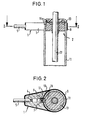
- FIG. 1 shows a vehicle occupant restraint system with a gas generator.
- the restraint system is a Belt tensioner.
- the gas generator includes an electric one Igniter 1 and a propellant 2.
- the electric Igniter 1 has a housing 3 with a not shown Passage opening in which the end 4 of a multi-core Cable 5 is shed, which is an electrical connection the igniter 1 with a trigger device, not shown manufactures.
- a pyrotechnic ignition material 7 is provided, by an ignition element also provided therein in the form of an ignition resistor connected to the cable end 4 8 can be ignited as soon as the trigger device delivers the corresponding signal.
- the housing 3 of the igniter 1 has a mounting ring 9 which is connected to a concave Housing section 10 is integrally formed.
- the receiving opening is the one designed as a separate unit Igniter 1 on a cylinder 11 of a piston-cylinder unit the belt tensioner attached.
- the annular propellant 2 is arranged in the interior thereof, the cylinder 11 also in this area Forms part of the propellant housing 15.
- the detonator 1 will through the mounting ring 9 from above onto the cylinder 11 pushed until an opening 17 in the housing 3 of the igniter 1st aligned with an opening 19 in the cylinder 11.
- the one in the Figures 1 and 2 shown igniter 1 can, for example, after removed from the propellant case 15 in the event of a collision be around the cylinder 11 together with that arranged in it Exchange propellant 2.
- the igniter 1 shown is characterized by a high Functional reliability off, since the ignition resistor 8 does not have an electrical connector is connected to the cable 5 is.
- the electrical signals in the event of a collision receive or deliver as shown in Figures 3 and 4 is, the igniter 1 with additional sensors or Switches are connected.
- Figure 3 is on a belt buckle 21 attached belt buckle switch 23 for seat occupancy query via an electrical line 25 to the detonator 1 connected.
- the housing 3 of the igniter 1 has on it Electrical plug contacts not shown on the outside which the line 25 can be connected via a mating connector 27 is.
- the plug contacts can be made using appropriate cables inside the igniter 1 with other than signals for the triggering of the igniter 1 conducting wires of the cable 5 be connected so that an electrical connection of the buckle switch 23 via line 25, mating connector 27, the electric igniter 1 and the cable 5 e.g. with the release device is present, which determines the triggering time.
- a mating connector 27 it can (see FIG. 4) the cable 5 before the electrical detonator Split 1 by wiring harness 29 to the buckle switch 23 and a further wiring harness 31 to the igniter 1 leads.
Landscapes
- Engineering & Computer Science (AREA)
- Mechanical Engineering (AREA)
- General Engineering & Computer Science (AREA)
- Chemical & Material Sciences (AREA)
- Combustion & Propulsion (AREA)
- Air Bags (AREA)
- Automotive Seat Belt Assembly (AREA)
Description
Die Erfindung betrifft ein Fahrzeuginsassen-Rückhaltesystem nach dem Oberbegriff des Anspruchs 1.The invention relates to a vehicle occupant restraint system according to the preamble of claim 1.
Ein elektrischer Zünder eines pyrotechnischen Gasgenerators als Teil eines Rückhaltesystems ist beispielsweise aus der EP 0 547 443 A1 bekannt. Der Zünder besteht aus einem Zündwiderstand, der in einen mit einem pyrotechnischen Treibmaterial gefüllten Raum ragt. Der Zündwiderstand ist mit am Gehäuse des Gasgenerators nach außen vorstehenden Kontaktstiften verbunden, auf die ein entsprechender Stecker aufgesetzt werden kann, an dem ein Kabel angebracht ist, das den Zünder mit einem Auslösegerät verbindet, das den Zeitpunkt des Auslösens der Zündung bestimmt. Die elektrische Steckverbindung muß extrem kontaktsicher und deshalb korrosionsbeständig sein, damit auch nach mehreren Jahren Fahrbetrieb noch eine sichere Auslösung in einem Kollisionsfall gewährleistet ist. Die Kontaktstifte und die entsprechenden Gegenteile werden deshalb teilweise vergoldet oder platiniert, was sie relativ teuer macht. Zudem muß der Stecker so ausgebildet sein, daß er sich trotz Vibrationen nicht löst und daß eine sichere Montage gewährleistet ist. An electric igniter of a pyrotechnic gas generator as part of a restraint system is known for example from EP 0 547 443 A1. The Detonator consists of an ignition resistor that is integrated into one a space filled with pyrotechnic propellant. The Ignition resistance is on the housing of the gas generator outside projecting pins connected to the one appropriate plug can be placed on the one Cable is attached to the igniter with a trigger device connects, which determines the timing of triggering the ignition. The electrical connector must be extremely reliable and therefore be corrosion-resistant, so even after safe operation in several years of driving a collision is guaranteed. The contact pins and the corresponding opposite parts are therefore partial gold or platinum plated, which makes them relatively expensive. moreover the plug must be designed so that it despite Does not solve vibrations and that ensures a safe installation is.
Darüber hinaus sind pyrotechnische Gasgeneratoren bekannt, die einen Treibsatz mit einem Treibsatzgehäuse aufweisen, an welchem das Kabel nicht lösbar befestigt ist. Das Kabel ist dabei mit einem im Inneren des Treibsatzgehäuses befindlichen Zündwiderstand verbunden, an den pyrotechnisches Treibmaterial angrenzt, so daß auf ein entsprechendes elektrisches Signal durch den Zündwiderstand direkt das Treibmaterial gezündet werden kann. Dieser bekannte Gasgenerator hat jedoch den Nachteil, daß im nicht montierten Zustand die entsprechenden Kontaktdrähte für die Auslösung des Treibmaterials kurzgeschlossen werden müssen, um ein unbeabsichtigtes Zünden, z.B. während des Transports, und ein Verschieben des Kolbens zu verhindern, was den kompletten Gasgenerator unbrauchbar macht.In addition, pyrotechnic gas generators are known which have a propellant charge with a propellant charge housing which the cable is not releasably attached. The cable is with one located inside the propellant housing Ignition resistance connected to the pyrotechnic Propellant adjacent, so that a corresponding electrical Signal through the ignition resistor directly the fuel can be ignited. This well-known gas generator has the disadvantage, however, that in the unassembled state appropriate contact wires for triggering the propellant must be short-circuited to prevent accidental Ignition, e.g. during transportation, and a move of the piston to prevent what the complete gas generator unusable.
Aus der WO 96/04154 ist ein gattungsgemäßes Fahrzeuginsassen-Rückhaltesystem in Form eines Gurtstraffers gezeigt. Dabei ist am stirnseitigen Ende des Zylinders eines Linearantriebs ein Gehäuse angebracht, das einen Treibsatz und einen seitlich angebrachten Zünder enthält, über den der Treibsatz aktiviert wird.WO 96/04154 describes a generic vehicle occupant restraint system shown in the form of a belt tensioner. It is at the front end of the A linear actuator cylinder is attached to a housing that contains a propellant and contains a detonator on the side that activates the propellant.
Ein weiterer Gurtstrafferantrieb ist aus der JP 63 212151 A bekannt, wobei hier ebenfalls stimseitig an einen Linearantrieb ein Gehäuse angesetzt ist, das eine integrierte Zünder-Treibladung enthält.Another belt tensioner drive is known from JP 63 212151 A, wherein here, too, a housing is attached to the end of a linear drive, the one contains integrated detonator propellant charge.
Die Erfindung schafft ein Fahrzeuginsassen-Rückhaltesystem, bei dem die Gefahr eines ungewollten Betätigens des Gasgenerators während des Transports reduziert wird und das insgesamt platzsparend ausgeführt ist.The invention provides a vehicle occupant restraint system in which the hazard an unwanted actuation of the gas generator during transportation is reduced and the overall space-saving design.
Dies wird durch ein Fahrzeuginsassen-Rückhaltesystem nach Anspruch 1 gelöst.This is achieved by a vehicle occupant restraint system according to claim 1 solved.
Die Erfindung führt zu mehreren Vorteilen, denn es wird ein Zünder verwendet, der keine aufwendigen Maßnahmen gegen Korrosion oder Lösen der elektrischen Steckverbindung vorsieht und dennoch eine höhere Sicherheit dahingehend gewährleistet, daß der Zünder stets mit dem Kabel in elektrischem Kontakt ist. Dies wird einerseits dadurch erreicht, daß der Zünder ein eigenes Gehäuse aufweist, in dem pyrotechnisches Zündmaterial mit einem elektrischen Zündelement und einem daran angeschlossenen Kabelende eingeschlossen ist. Der erfindungsgemäße elektrische Zünder ist unmittelbar an dem Kabel angebracht, so daß die bislang übliche Steckverbindung entfällt. The invention leads to several advantages because an igniter is used, of no complex measures against corrosion or loosening the electrical connector provides and still one ensuring greater security in that the detonator is always in electrical contact with the cable. this will achieved on the one hand in that the detonator has its own Has housing in the pyrotechnic ignition material with an electrical ignition element and a connected to it Cable end is included. The invention electrical detonator is attached directly to the cable, so that the usual plug connection is eliminated.
Die Gefahr des ungewollten Betätigen des Gasgenerators während des Transports wird bei einem mit einem elektrischen Zünder ausgestatteten Fahrzeuginsassen-Rückhaltesystem mit einem Treibsatz in einem Treibsatzgehäuse und einem darin enthaltenen pyrotechnischen Treibmaterial dadurch ausgeschlossen, daß das Gehäuse des Zünders getrennt vom Treibsatz transportiert, jedoch am Treibsatzgehäuse in solcher Weise befestigt werden kann, daß das Treibmaterial durch einander gegenüberliegende Öffnungen im Gehäuse und im Treibsatzgehäuse hindurch anzündbar ist. Der Zünder und der Treibsatz bilden getrennte Einheiten, die erst bei der Montage im Fahrzeug aneinandergefügt werden müssen. Das erfindungsgemäße Rückhaltesystem ist z.B. bei einem Gurtstraffer einsetzbar.The danger of unintentionally operating the gas generator during transport, one with one electric detonator equipped The vehicle occupant restraint system with a propellant in a propellant housing and a pyrotechnic propellant contained therein excluded that the detonator housing separated transported by the propellant, but on the propellant housing in can be attached in such a way that the propellant through opposite openings in the housing and in Propellant housing can be ignited through. The detonator and the Propellant form separate units, which are only during assembly must be joined together in the vehicle. The restraint system according to the invention is e.g. at a Belt tensioners can be used.
Gemäß einer bevorzugten Ausführungsform ist das Kabelende in einer Durchtrittsöffnung des Gehäuses vergossen, wodurch dieses im Bereich der Kabelbefestigung zudem gegen Feuchtigkeitseintritt geschützt ist.According to a preferred embodiment is the cable end in a passage opening potted the housing, making this in the area of the cable attachment is also protected against moisture ingress.
Eine einfache Montage des Zünders am Treibsatzgehäuse wird dadurch erreicht, daß an das Gehäuse des Zünders als Befestigungsmittel mindestens ein Teil einer Steckverbindung angeformt ist, mittels der der Zünder an dem Treibsatzgehäuse angebracht werden kann. Da die Steckverbindung zwischen Zünder und Treibsatzgehäuse keine elektrische Verbindung darstellt, können Treibsatz und Zünder ohne elektrische Kontaktprobleme erst im Fahrzeug auf einfache Weise aneinander angeschlossen werden.A simple assembly of the igniter on the propellant housing is thereby achieved that to the housing of the igniter as a fastener at least part of a connector is formed by means of which the igniter on the propellant housing can be attached. Because the connector between Igniter and propellant case no electrical connection represents propellant and igniter without electrical Contact problems only in a simple way in the vehicle be connected.
Eine bevorzugte Steckverbindung zwischen Zünder und Treibsatzgehäuse besteht darin, daß am Gehäuse des Zünders als Befestigungsmittel ein Befestigungsring angeformt ist, der als Steckverbindung dient und der auf ein zylindrisches Treibsatzgehäuse aufgesteckt werden kann.A preferred connector between igniter and propellant case is that on the housing of the igniter as Fastening means a fastening ring is molded on serves as a connector and that on a cylindrical Propellant housing can be plugged on.
Gemäß einer bevorzugten Ausführungsform ist am Gehäuse des Zünders mindestens ein mit dem Kabel verbundener elektrischer Steckkontakt angeformt, mittels dem über einen einklinkbaren Gegenstecker mindestens ein weiterer Sensor und/oder mindestens ein Schalter an das Kabel angeschlossen werden kann. Dies dient dazu, möglichst wenig separate Leitungen im Fahrzeug legen zu müssen, so daß zum Beispiel ein Gurtschloßsensor oder ein in der Nähe des Zünders vorgesehener Schalter an das Kabel angeschlossen werden kann. Für die Auslösung der Zündung verantwortliche andere Sensoren können so sehr einfach angeschlossen oder andere Sicherheitssysteme im Fahrzeug im Kollisionsfall durch entsprechende Schalter ausgelöst werden.According to a preferred embodiment, the housing of the Igniter at least one electrical connected to the cable Molded plug contact, by means of a snap-in mating connector at least one additional sensor and / or at least one switch connected to the cable can be. This serves to keep as few separate lines as possible to have to put in the vehicle, so that for example a Belt buckle sensor or one provided near the igniter Switch can be connected to the cable. For other sensors responsible for triggering the ignition can be connected very easily or other security systems in the vehicle in the event of a collision by appropriate Switches are triggered.
Eine hierzu alternative Ausführung sieht vor, daß das Kabel als mehradriges Kabel ausgebildet ist, von dem einige Adern vor dem Gehäuse zu mindestens einem weiteren Sensor und/oder mindestens einem Schalter abzweigen. Dadurch können weitere Steckkontakte vermieden werden.An alternative embodiment provides that the cable is designed as a multi-core cable, of which some wires in front of the housing to at least one further sensor and / or branch off at least one switch. This allows more Plug contacts can be avoided.
Gemäß einer bevorzugten Ausführungsform ist das Treibsatzgehäuse zylindrisch und das Gehäuse des Zünders weist einen entsprechend konkaven Gehäuseabschnitt mit einem sich daran anschließenden Befestigungsring auf, so daß eine Aufnahmeöffnung entsteht, durch die das Gehäuse auf das Treibsatzgehäuse lösbar aufgesteckt werden kann. Der konkave Gehäuseabschnitt schafft eine gasdichte Verbindung des Inneren des Gehäuses mit dem Inneren des Treibsatzgehäuses, da er großflächig am Treibsatzgehäuse anliegt.According to a preferred embodiment the propellant housing is cylindrical and the housing of the igniter has a correspondingly concave Housing section with an adjoining fastening ring on so that a receiving opening is created through which the housing is detachably attached to the propellant housing can be. The concave housing section creates a gas-tight connection of the interior of the housing with the Interior of the propellant housing, since it is largely on the propellant housing is applied.
Vorzugsweise ist der Gasgenerator so ausgebildet, daß der Treibsatz im Inneren eines Zylinders als Teil einer Kolben-Zylinder-Einheit eines Gurtstraffers angeordnet ist, wobei der Zünder am Zylinder befestigt werden kann. Bei dieser Ausführungsform kann der Treibsatz sehr platzsparend im Fahrzeug eingebaut werden, was dadurch noch verbessert werden kann, daß der Treibsatz kreisringförmig ausgebildet ist und die Wandung des Zylinders zumindest teilweise das Treibsatzgehäuse bildet.The gas generator is preferably designed such that that the propellant inside a cylinder as Part of a piston-cylinder unit of a belt tensioner arranged with the igniter attached to the cylinder can. In this embodiment, the propellant can be very space-saving installation in the vehicle, what else can be improved that the propellant ring-shaped is formed and the wall of the cylinder at least partially forms the propellant housing.
Weitere Merkmale und Vorteile der Erfindung ergeben sich aus der nachfolgenden Beschreibung und aus den nachfolgenden Zeichnungen, auf die Bezug genommen wird. In den Zeichnungen zeigen:
- Figur 1 eine Längsschnittansicht durch einen Zylinder eines erfindungsgemäßen Gurtstraffers mit einem Gasgenerator mit einem Treibsatz und einem am Zylinder arretierten erfindungsgemäßen elektrischen Zünder,
Figur 2 eine Schnittansicht nach der Linie II-II in Figur 1,- Figur 3 eine zweite Ausführungsform des erfindungsgemäßen Fahrzeuginsassen-Rückhaltesystems, mit einem elektrischen Zünder, der mit einer elektrischen Steckverbindung ausgebildet ist, an die ein Gurtschloßschalter angeschlossen ist, und
- Figur 4 eine dritte Ausführungsform des erfindungsgemäßen Fahrzeuginsassen-Rückhaltesystems.
- FIG. 1 shows a longitudinal sectional view through a cylinder of a belt tensioner according to the invention with a gas generator with a propellant charge and an electrical igniter according to the invention locked on the cylinder,
- FIG. 2 shows a sectional view along the line II-II in FIG. 1,
- Figure 3 shows a second embodiment of the vehicle occupant restraint system according to the invention, with an electrical igniter, which is designed with an electrical plug connection to which a belt buckle switch is connected, and
- Figure 4 shows a third embodiment of the vehicle occupant restraint system according to the invention.
In Figur 1 ist ein Farzeuginsassen-Rückhaltesystem mit einem Gasgenerator gezeigt. Das Rückhaltesystem ist ein
Gurtstraffers. Der Gasgenerator umfaßt einen elektrischen
Zünder 1 und einen Treibsatz 2. Der elektrische
Zünder 1 weist ein Gehäuse 3 mit einer nicht gezeigten
Durchtrittsöffnung auf, in welcher das Ende 4 eines mehradrigen
Kabels 5 vergossen ist, das eine elektrische Verbindung
des Zünders 1 mit einem nicht gezeigten Auslösegerät
herstellt. Im Inneren des Gehäuses 3 ist, umgeben von einer
Vergußmasse 6, ein pyrotechnisches Zündmaterial 7 vorgesehen,
das durch ein ebenfalls darin vorgesehenes Zündelement
in Form eines an das Kabelende 4 angeschlossenen Zündwiderstands
8 gezündet werden kann, sobald das Auslösegerät ein
entsprechendes Signal liefert. Das Gehäuse 3 des Zünders 1
weist einen Befestigungsring 9 auf, der an einen konkaven
Gehäuseabschnitt 10 angeformt ist. Mittels der entstehenden
Aufnahmeöffnung ist der als separate Einheit ausgebildete
Zünder 1 an einem Zylinder 11 einer Kolben-Zylinder-Einheit
des Gurtstraffers befestigt. Am oberen Ende des Zylinders 11
ist in dessen Innerem der kreisringförmige Treibsatz 2 angeordnet,
wobei der Zylinder 11 in diesem Bereich auch einen
Teil des Treibsatzgehäuses 15 bildet. Der Zünder 1 wird
durch den Befestigungsring 9 von oben auf den Zylinder 11
geschoben, bis eine Öffnung 17 im Gehäuse 3 des Zünders 1
mit einer Öffnung 19 im Zylinder 11 fluchtet. Der in den
Figuren 1 und 2 gezeigte Zünder 1 kann zum Beispiel nach
einem Kollisionsfall wieder vom Treibsatzgehäuse 15 entfernt
werden, um den Zylinder 11 samt dem in ihm angeordneten
Treibsatz 2 auszutauschen. FIG. 1 shows a vehicle occupant restraint system with a gas generator. The restraint system is a
Belt tensioner. The gas generator includes an electric one
Igniter 1 and a
Der dargestellte Zünder 1 zeichnet sich durch eine hohe Funktionssicherheit aus, da der Zündwiderstand 8 nicht über eine elektrische Steckverbindung mit dem Kabel 5 verbunden ist.The igniter 1 shown is characterized by a high Functional reliability off, since the ignition resistor 8 does not have an electrical connector is connected to the cable 5 is.
Sind in der Nähe des Zünders 1 weitere Sensoren oder Schalter
angeordnet, die im Kollisionsfall elektrische Signale
erhalten oder abgeben, kann, wie in den Figuren 3 und 4 gezeigt
ist, der Zünder 1 mit weiteren Sensoren oder auch
Schaltern verbunden sein. In Figur 3 ist ein an einem Gurtschloß
21 angebrachter Gurtschloßschalter 23 zur Sitzbelegungsabfrage
über eine elektrische Leitung 25 mit dem Zünder
1 verbunden. Das Gehäuse 3 des Zünders 1 hat hierzu an seiner
Außenseite nicht gezeigte elektrische Steckkontakte, an
die die Leitung 25 über einen Gegenstecker 27 anschließbar
ist. Die Steckkontakte können dabei über entsprechende Leitungen
im Inneren des Zünders 1 mit anderen als Signale für
die Auslösung des Zünders 1 leitenden Adern des Kabels 5
verbunden sein, so daß eine elektrische Verbindung des Gurtschloßschalter
23 über die Leitung 25, den Gegenstecker 27,
den elektrischen Zünder 1 und das Kabel 5 z.B. mit dem Auslösegerät
vorhanden ist, das den Auslösezeitpunkt bestimmt.There are 1 other sensors or switches near the igniter
arranged, the electrical signals in the event of a collision
receive or deliver, as shown in Figures 3 and 4
is, the igniter 1 with additional sensors or
Switches are connected. In Figure 3 is on a
Wenn ein Gegenstecker 27 vermieden werden soll, kann sich
(vgl. Fig. 4) das Kabel 5 bereits vor dem elektrischen Zünder
1 aufteilen, indem ein Kabelstrang 29 zu dem Gurtschloßschalter
23 und ein weiterer Kabelstrang 31 zum Zünder 1
führt.If a
Durch die in den Figuren 3 und 4 gezeigten Zünder ist es sehr leicht möglich, nachträglich in einem Fahrzeug eingebaute Sicherheitssysteme, wie zum Beispiel einen Gurtschloßschalter, elektrisch an andere Teile anzuschließen.It is through the detonators shown in Figures 3 and 4 very easily possible, retrofitted in a vehicle Security systems, such as a seat belt buckle switch, to be electrically connected to other parts.
Im Falle einer Kollision wird über das Kabel 5 ein elektrisches
Signal über das Kabel 5 von dem Auslösegerät zu dem
Zündwiderstand 8 im Inneren des Gehäuses 3 geleitet, um das
Zündmaterial 7 zu zünden. Durch die Öffnungen 17 und 19 hindurch
wird daraufhin das Treibmaterial 13 angezündet, wodurch
Gas erzeugt wird, welches einen nicht gezeigten Kolben
antreibt, der über eine Kolbenstange 33 mit dem Gurtschloß
21 verbunden ist.In the event of a collision, an electrical connection is made via the cable 5
Signal on the cable 5 from the trigger device to the
Ignition resistor 8 passed inside the housing 3 to the
Ignite material 7. Through
Claims (10)
- A vehicle occupant restraint system, comprising
a piston/cylinder unit including a cylinder (11) and a piston arranged for sliding movement therein,
a pyrotechnical gas generator to actuate the piston/cylinder unit, the gas generator including a propellant charge housing (15) having a propellant charge (2) contained therein with a pyrotechnical material (13), and
an electrical igniter (1) including pyrotechnical ignition material (7) and an electrical ignition element,
characterized in that
the pyrotechnical gas generator is arranged inside the cylinder (11), and the igniter (1) has a housing (3) of its own which is transportable separately from the propellant charge (2) and in which the ignition material (7), the ignition element and a cable end (4) connected thereto are enclosed, and
that the igniter (1) is mounted radially at the cylinder (11) such that a radial opening (19) in the cylinder (11) faces an opening (17) in the housing (3) of the igniter (1) and the propellant material (13) is ignitable through the openings (17, 19). - The restraint system as set forth in claim 1, characterized in that the end (29) of the cable (5) is sealed in a passage opening of the housing (3).
- The restraint system as set forth in either of the preceding claims, characterized in that the igniter (1) may be releasably secured as a unit to the propellant charge housing (15) of the gas generator.
- The restraint system as set forth in claim 3, characterized in that at least one part of a plug connection is molded integrally with the housing (3) of the igniter (1) as a fastener means, the igniter (1) being attachable to the propellant charge housing (15) by means of this plug connection.
- The restraint system as set forth in claim 4, characterized in that a fastener ring (9) is molded integrally with the housing (3) as a fastener means, the fastener ring serving as a plug connection and being mountable on a cylindrical propellant charge housing (15).
- The restraint system as set forth in any of the preceding claims, characterized in that at least one electrical plug contact connected to the cable (5) is molded integrally with the housing (3), at least one further sensor and/or at least one switch being connectable to the cable (5) by means of the plug contact via a latchable mating connector (27).
- The restraint system as set forth in any of claims 1 to 6, characterized in that the cable (5) is configured as a multi-core cable, of which a few cores are branched off prior to the housing (3) to at least one further sensor and/or to at least one switch.
- The restraint system as set forth in claim 7, characterized in that at the end of the branched-off cores plug connections are attached.
- The restraint system as set forth in any of the preceding claims, characterized in that the propellant charge housing (15) is cylindrical and the housing (3) features a correspondingly concave housing section (10) having a fastener ring (9) adjacent thereto so that a receiving opening is defined through which the housing (3) can be releasably mounted on the propellant charge housing (15).
- The restraint system as set forth in any of the preceding claims, characterized in that the propellant charge (2) is configured in the shape of a circular ring and the wall of the cylinder (11) forms at least in part the propellant charge housing (15).
Applications Claiming Priority (2)
| Application Number | Priority Date | Filing Date | Title |
|---|---|---|---|
| DE29608194U | 1996-05-06 | ||
| DE29608194U DE29608194U1 (en) | 1996-05-06 | 1996-05-06 | Electrical igniter of a pyrotechnic gas generator |
Publications (3)
| Publication Number | Publication Date |
|---|---|
| EP0806626A2 EP0806626A2 (en) | 1997-11-12 |
| EP0806626A3 EP0806626A3 (en) | 2000-10-11 |
| EP0806626B1 true EP0806626B1 (en) | 2004-06-30 |
Family
ID=8023606
Family Applications (1)
| Application Number | Title | Priority Date | Filing Date |
|---|---|---|---|
| EP97107451A Expired - Lifetime EP0806626B1 (en) | 1996-05-06 | 1997-05-06 | Safety belt tension retractors system |
Country Status (8)
| Country | Link |
|---|---|
| US (1) | US5936186A (en) |
| EP (1) | EP0806626B1 (en) |
| JP (1) | JP3034225B2 (en) |
| KR (1) | KR100235790B1 (en) |
| CN (1) | CN1167876A (en) |
| BR (1) | BR9703071A (en) |
| DE (2) | DE29608194U1 (en) |
| ES (1) | ES2110384T3 (en) |
Families Citing this family (8)
| Publication number | Priority date | Publication date | Assignee | Title |
|---|---|---|---|---|
| DE29612781U1 (en) * | 1996-07-23 | 1996-11-21 | Trw Repa Gmbh | Pyrotechnic linear drive device for a belt tensioner |
| US6142524A (en) * | 1998-12-14 | 2000-11-07 | Trw Vehicle Safety Systems Inc. | Seat belt pretensioner apparatus |
| ATE372499T1 (en) * | 2002-02-09 | 2007-09-15 | Delphi Tech Inc | PYROTECHNIC IGNITION CHAIN WITH A PLASTIC IGNITION CARRIER WITH INTEGRATED METAL INSERT |
| US7527290B2 (en) * | 2003-10-21 | 2009-05-05 | Automotive Systems Laboratory, Inc. | Pressurized gas release mechanism |
| US7597354B2 (en) * | 2004-10-28 | 2009-10-06 | Automotive Systems Laboratory, Inc. | Pressurized gas release mechanism |
| US7370721B2 (en) * | 2004-12-03 | 2008-05-13 | Autoliv Asp, Inc. | Seatbelt tensioning device and method |
| DE102011013255B4 (en) * | 2011-03-07 | 2024-01-04 | Zf Airbag Germany Gmbh | Unlocking device |
| DE102016120988A1 (en) * | 2016-11-03 | 2018-05-03 | Trw Automotive Safety Systems Gmbh | A harness for a gas bag module of a vehicle occupant safety system, gas bag module, vehicle wiring and vehicle occupant safety system with such a wire harness and manufacturing method |
Family Cites Families (22)
| Publication number | Priority date | Publication date | Assignee | Title |
|---|---|---|---|---|
| US1516009A (en) * | 1924-06-18 | 1924-11-18 | Atlas Powder Co | Electric detonator |
| US2934014A (en) * | 1956-12-06 | 1960-04-26 | Rex L Smith | Igniter assemblies |
| US3567190A (en) * | 1968-12-12 | 1971-03-02 | Ray D Moran | Drum car and coupling apparatus for carrying and feeding concrete in tunnels |
| FR2239870A1 (en) * | 1973-08-03 | 1975-02-28 | Poudres & Explosifs Ste Nale | |
| DE2505625A1 (en) * | 1975-02-11 | 1976-08-19 | Volkswagenwerk Ag | SAFETY DEVICE FOR VEHICLES, IN PARTICULAR MOTOR VEHICLES |
| US4337702A (en) * | 1980-06-09 | 1982-07-06 | The United States Of America As Represented By The Secretary Of The Army | Electroexplosive and percussion safe and arm device |
| DE3044951C2 (en) * | 1980-11-28 | 1986-03-27 | Repa Feinstanzwerk Gmbh, 7071 Alfdorf | Back tensioner for a seat belt |
| JPS58105766A (en) * | 1981-12-10 | 1983-06-23 | レパ・フアインシユタンツヴエルク・ゲゼルシヤフト・ミツト・ベシユレンクテル・ハフツング | Returning apparatus for safety belt |
| FR2569686B1 (en) * | 1984-09-05 | 1986-11-21 | Poudres & Explosifs Ste Nale | ULTRA-FAST GAS GENERATOR WITH ENHANCED SECURITY |
| FR2594891B1 (en) * | 1986-02-21 | 1989-10-13 | Poudres & Explosifs Ste Nale | IGNITER FIXABLE IN THE NOZZLE OF A PROPELLER |
| JPS63212151A (en) * | 1987-02-26 | 1988-09-05 | Fuji Kiko Co Ltd | Emergency take-up device for safety belt |
| GB8802328D0 (en) * | 1988-02-03 | 1988-03-02 | Ici Plc | Multi-directional initiator for explosives |
| JPH0248464A (en) * | 1988-08-05 | 1990-02-19 | Hakusan Seisakusho:Kk | Barium titanate-based semiconductor porcelain |
| JP2879613B2 (en) * | 1991-03-18 | 1999-04-05 | 本田技研工業株式会社 | Occupant protection device |
| JP2967576B2 (en) * | 1992-02-17 | 1999-10-25 | 日油技研工業株式会社 | Squib and manufacturing method |
| JP2757697B2 (en) * | 1992-08-04 | 1998-05-25 | 日産自動車株式会社 | Seat belt equipment |
| US5626359A (en) * | 1993-12-02 | 1997-05-06 | Trw Vehicle Safety Systems, Inc. | Method and apparatus for controlling an actuatable restraining device in response to discrete control zones |
| DE4404462A1 (en) * | 1994-02-11 | 1995-08-17 | Trw Repa Gmbh | Belt tensioners for a seat belt |
| WO1996004154A1 (en) * | 1994-08-04 | 1996-02-15 | Alliedsignal Inc. | Method and apparatus for reducing occupant injury in frontal collisions |
| US5605202A (en) * | 1995-06-07 | 1997-02-25 | Itt Automotive, Inc. | Apparatus and method for enhancing performance of an occupant restraint system in a vehicle |
| US5662353A (en) * | 1995-12-06 | 1997-09-02 | Trw Vehicle Safety Systems Inc. | Electrical conductor for air bag inflator |
| DE29612781U1 (en) * | 1996-07-23 | 1996-11-21 | Trw Repa Gmbh | Pyrotechnic linear drive device for a belt tensioner |
-
1996
- 1996-05-06 DE DE29608194U patent/DE29608194U1/en not_active Expired - Lifetime
-
1997
- 1997-05-02 KR KR1019970016960A patent/KR100235790B1/en not_active IP Right Cessation
- 1997-05-06 EP EP97107451A patent/EP0806626B1/en not_active Expired - Lifetime
- 1997-05-06 US US08/851,787 patent/US5936186A/en not_active Expired - Fee Related
- 1997-05-06 ES ES97107451T patent/ES2110384T3/en not_active Expired - Lifetime
- 1997-05-06 BR BR9703071A patent/BR9703071A/en not_active Application Discontinuation
- 1997-05-06 CN CN97111104A patent/CN1167876A/en active Pending
- 1997-05-06 JP JP9115906A patent/JP3034225B2/en not_active Expired - Fee Related
- 1997-05-06 DE DE59711738T patent/DE59711738D1/en not_active Expired - Fee Related
Also Published As
| Publication number | Publication date |
|---|---|
| JP3034225B2 (en) | 2000-04-17 |
| ES2110384T3 (en) | 2005-02-16 |
| KR970075671A (en) | 1997-12-10 |
| EP0806626A2 (en) | 1997-11-12 |
| ES2110384T1 (en) | 1998-02-16 |
| DE29608194U1 (en) | 1996-10-02 |
| BR9703071A (en) | 1998-11-10 |
| CN1167876A (en) | 1997-12-17 |
| EP0806626A3 (en) | 2000-10-11 |
| JPH1053104A (en) | 1998-02-24 |
| KR100235790B1 (en) | 1999-12-15 |
| DE59711738D1 (en) | 2004-08-05 |
| US5936186A (en) | 1999-08-10 |
Similar Documents
| Publication | Publication Date | Title |
|---|---|---|
| EP0888227B1 (en) | Ignition device for release of restraining means in a motor vehicle | |
| EP0742951B1 (en) | Vehicle battery cable clamp | |
| EP2287047B1 (en) | Airbag module | |
| EP0547443B1 (en) | Electric connector on a pyrotechnic gas generator provided with an electric igniter | |
| DE4422249A1 (en) | Device for interrupting the current flow in the ground cable of a motor vehicle battery | |
| EP2816372A2 (en) | Distance sensor for a motor vehicle, and assembly of a plurality of distance sensors | |
| DE19926072A1 (en) | Current breaker for emergency disconnection of automobile battery | |
| EP0725412A2 (en) | Safety device for a current line in vehicles | |
| EP0803412B1 (en) | Safety belt system | |
| EP0806626B1 (en) | Safety belt tension retractors system | |
| EP0882317B1 (en) | Vehicle battery cable clamp | |
| DE4415373A1 (en) | Gas generator for a vehicle restraint system | |
| DE4425307A1 (en) | Electrical safety switch for motor vehicle airbag system | |
| DE10202920A1 (en) | Electrical pluggable connector e.g. for motor vehicle passenger restraint system, has contact springs electrically joined to electrical cable for lockably receiving plug | |
| DE19609908A1 (en) | Gas generator, in particular for belt tensioners | |
| EP1715195B1 (en) | Initiator unit for a safety system, particularly for a vehicle airbag or belt tensioner | |
| EP0521850B1 (en) | Arrangement for securing an airbag on the steering wheel of a vehicle | |
| DE10228669C1 (en) | Safety belt lock has illuminated button with electrically controllable lighting foil on visible front supplied with electrical power by source on fixed part with contactless air gap bridging | |
| EP1018456A2 (en) | Gas generator with integrated electrical component | |
| DE19858302C2 (en) | Signaling system for motor vehicles | |
| DE4008960A1 (en) | Collision safety arrangement for motor vehicle - comprises sensor releasing ignition device for inflatable protective bag with associated gas generator, all mounted on steering wheel | |
| DE102004037277B4 (en) | Electric multiple plug | |
| DE19816217B4 (en) | Airbag control unit with cylindrical housing | |
| DE4401711C2 (en) | Mechanical acceleration sensor | |
| EP0464248B1 (en) | Vehicle steering-wheel arrangement comprising an airbag and a casing for the electronic control of this steering-wheel arrangement |
Legal Events
| Date | Code | Title | Description |
|---|---|---|---|
| PUAI | Public reference made under article 153(3) epc to a published international application that has entered the european phase |
Free format text: ORIGINAL CODE: 0009012 |
|
| AK | Designated contracting states |
Kind code of ref document: A2 Designated state(s): DE ES FR GB IT |
|
| GBC | Gb: translation of claims filed (gb section 78(7)/1977) | ||
| EL | Fr: translation of claims filed | ||
| REG | Reference to a national code |
Ref country code: ES Ref legal event code: BA2A Ref document number: 2110384 Country of ref document: ES Kind code of ref document: T1 |
|
| RAP1 | Party data changed (applicant data changed or rights of an application transferred) |
Owner name: TRW OCCUPANT RESTRAINT SYSTEMS GMBH & CO. KG |
|
| PUAL | Search report despatched |
Free format text: ORIGINAL CODE: 0009013 |
|
| AK | Designated contracting states |
Kind code of ref document: A3 Designated state(s): DE ES FR GB IT |
|
| 17P | Request for examination filed |
Effective date: 20010102 |
|
| 17Q | First examination report despatched |
Effective date: 20021018 |
|
| RIC1 | Information provided on ipc code assigned before grant |
Ipc: 7B 60R 22/46 A |
|
| RTI1 | Title (correction) |
Free format text: SAFETY BELT TENSION RETRACTORS SYSTEM |
|
| GRAP | Despatch of communication of intention to grant a patent |
Free format text: ORIGINAL CODE: EPIDOSNIGR1 |
|
| GRAS | Grant fee paid |
Free format text: ORIGINAL CODE: EPIDOSNIGR3 |
|
| GRAA | (expected) grant |
Free format text: ORIGINAL CODE: 0009210 |
|
| RAP1 | Party data changed (applicant data changed or rights of an application transferred) |
Owner name: TRW AUTOMOTIVE GMBH |
|
| AK | Designated contracting states |
Kind code of ref document: B1 Designated state(s): DE ES FR GB IT |
|
| REG | Reference to a national code |
Ref country code: GB Ref legal event code: FG4D Free format text: NOT ENGLISH |
|
| REF | Corresponds to: |
Ref document number: 59711738 Country of ref document: DE Date of ref document: 20040805 Kind code of ref document: P |
|
| GBT | Gb: translation of ep patent filed (gb section 77(6)(a)/1977) |
Effective date: 20040810 |
|
| REG | Reference to a national code |
Ref country code: ES Ref legal event code: FG2A Ref document number: 2110384 Country of ref document: ES Kind code of ref document: T3 |
|
| ET | Fr: translation filed | ||
| PG25 | Lapsed in a contracting state [announced via postgrant information from national office to epo] |
Ref country code: IT Free format text: LAPSE BECAUSE OF NON-PAYMENT OF DUE FEES;WARNING: LAPSES OF ITALIAN PATENTS WITH EFFECTIVE DATE BEFORE 2007 MAY HAVE OCCURRED AT ANY TIME BEFORE 2007. THE CORRECT EFFECTIVE DATE MAY BE DIFFERENT FROM THE ONE RECORDED. Effective date: 20050506 Ref country code: GB Free format text: LAPSE BECAUSE OF NON-PAYMENT OF DUE FEES Effective date: 20050506 |
|
| PLBE | No opposition filed within time limit |
Free format text: ORIGINAL CODE: 0009261 |
|
| STAA | Information on the status of an ep patent application or granted ep patent |
Free format text: STATUS: NO OPPOSITION FILED WITHIN TIME LIMIT |
|
| PG25 | Lapsed in a contracting state [announced via postgrant information from national office to epo] |
Ref country code: ES Free format text: LAPSE BECAUSE OF NON-PAYMENT OF DUE FEES Effective date: 20050507 |
|
| PGFP | Annual fee paid to national office [announced via postgrant information from national office to epo] |
Ref country code: FR Payment date: 20050517 Year of fee payment: 9 |
|
| PGFP | Annual fee paid to national office [announced via postgrant information from national office to epo] |
Ref country code: DE Payment date: 20050531 Year of fee payment: 9 |
|
| 26N | No opposition filed |
Effective date: 20050331 |
|
| GBPC | Gb: european patent ceased through non-payment of renewal fee |
Effective date: 20050506 |
|
| REG | Reference to a national code |
Ref country code: ES Ref legal event code: FD2A Effective date: 20050507 |
|
| PG25 | Lapsed in a contracting state [announced via postgrant information from national office to epo] |
Ref country code: DE Free format text: LAPSE BECAUSE OF NON-PAYMENT OF DUE FEES Effective date: 20061201 |
|
| REG | Reference to a national code |
Ref country code: FR Ref legal event code: ST Effective date: 20070131 |
|
| PG25 | Lapsed in a contracting state [announced via postgrant information from national office to epo] |
Ref country code: FR Free format text: LAPSE BECAUSE OF NON-PAYMENT OF DUE FEES Effective date: 20060531 |