EP0805915B1 - Device for removing substances in gas and vapour form in a stream of exhaust air - Google Patents
Device for removing substances in gas and vapour form in a stream of exhaust air Download PDFInfo
- Publication number
- EP0805915B1 EP0805915B1 EP96900497A EP96900497A EP0805915B1 EP 0805915 B1 EP0805915 B1 EP 0805915B1 EP 96900497 A EP96900497 A EP 96900497A EP 96900497 A EP96900497 A EP 96900497A EP 0805915 B1 EP0805915 B1 EP 0805915B1
- Authority
- EP
- European Patent Office
- Prior art keywords
- cartridges
- exhaust air
- gas
- catalyst
- active material
- Prior art date
- Legal status (The legal status is an assumption and is not a legal conclusion. Google has not performed a legal analysis and makes no representation as to the accuracy of the status listed.)
- Expired - Lifetime
Links
Images


Classifications
-
- F—MECHANICAL ENGINEERING; LIGHTING; HEATING; WEAPONS; BLASTING
- F23—COMBUSTION APPARATUS; COMBUSTION PROCESSES
- F23G—CREMATION FURNACES; CONSUMING WASTE PRODUCTS BY COMBUSTION
- F23G7/00—Incinerators or other apparatus for consuming industrial waste, e.g. chemicals
- F23G7/06—Incinerators or other apparatus for consuming industrial waste, e.g. chemicals of waste gases or noxious gases, e.g. exhaust gases
- F23G7/07—Incinerators or other apparatus for consuming industrial waste, e.g. chemicals of waste gases or noxious gases, e.g. exhaust gases in which combustion takes place in the presence of catalytic material
-
- F—MECHANICAL ENGINEERING; LIGHTING; HEATING; WEAPONS; BLASTING
- F01—MACHINES OR ENGINES IN GENERAL; ENGINE PLANTS IN GENERAL; STEAM ENGINES
- F01N—GAS-FLOW SILENCERS OR EXHAUST APPARATUS FOR MACHINES OR ENGINES IN GENERAL; GAS-FLOW SILENCERS OR EXHAUST APPARATUS FOR INTERNAL COMBUSTION ENGINES
- F01N3/00—Exhaust or silencing apparatus having means for purifying, rendering innocuous, or otherwise treating exhaust
- F01N3/08—Exhaust or silencing apparatus having means for purifying, rendering innocuous, or otherwise treating exhaust for rendering innocuous
- F01N3/10—Exhaust or silencing apparatus having means for purifying, rendering innocuous, or otherwise treating exhaust for rendering innocuous by thermal or catalytic conversion of noxious components of exhaust
- F01N3/24—Exhaust or silencing apparatus having means for purifying, rendering innocuous, or otherwise treating exhaust for rendering innocuous by thermal or catalytic conversion of noxious components of exhaust characterised by constructional aspects of converting apparatus
- F01N3/28—Construction of catalytic reactors
Landscapes
- Engineering & Computer Science (AREA)
- Chemical & Material Sciences (AREA)
- Chemical Kinetics & Catalysis (AREA)
- Environmental & Geological Engineering (AREA)
- Mechanical Engineering (AREA)
- General Engineering & Computer Science (AREA)
- Health & Medical Sciences (AREA)
- Toxicology (AREA)
- Combustion & Propulsion (AREA)
- Exhaust Gas Treatment By Means Of Catalyst (AREA)
- Electrical Discharge Machining, Electrochemical Machining, And Combined Machining (AREA)
- Exhaust Gas After Treatment (AREA)
- Filtering Of Dispersed Particles In Gases (AREA)
Abstract
Description
Die Erfindung bezieht sich auf eine Vorrichtung zur Abluftreinigung gemäß den im Oberbegriff des Patentanspruchs 1 angegebenen Merkmalen.The invention relates to a device for exhaust air purification according to the The preamble of claim 1 features specified.
Aus der WO 93/23657 ist eine derartige Vorrichtung bekannt, welche mit Diesel-Motoren zum Einsatz gelangt, um Rußpartikel zu filtern und insbesondere in gasförmiges Kohlendioxid umzuwandeln. Diese Vorrichtung gelangt vor allem in Kraftfahrzeugen zum Einsatz und wird nach vorgegebener Kilometerleistung oder bei Feststellung einer sich im Laufe der Zeit ergbenden Unwirksamkeit insgesamt entsorgt und durch eine neue Vorrichtung ersetzt. Die Vorrichtung enthält in einem Gehäuse eine Anzahl von axial im Abstand angeordnete Patronen mit einem perforierten Innenmantel und einem gasdurchlässig ausgebildeten Außenmantel mit aktivem Material, wobei ein Ersatz des aktiven Materials oder ein Austausch von Teilkomponenten der Vorrichtung nicht ohne weiteres möglich ist. Die einzelnen Patronen sind im Bereich der Gasaustrittsseite mittels Bolzen verschraubt, doch ist im Bereich der Gaseintrittsseite eine Platte mit den offenen Enden der einzelnen Rohre verschweißt. Eine Wiederaufbereitung der Vorrichtung oder die Wiederverwendung von einzelnen Komponenten derselben ist nicht ohne weiteres möglich.Such a device is known from WO 93/23657, which has diesel engines used to filter soot particles and especially in gaseous Convert carbon dioxide. This device is used primarily in motor vehicles used and is based on the specified mileage or upon detection an ineffectiveness that arises over time and replaced with a new device. The device contains in a housing a number of axially spaced cartridges with a perforated Inner jacket and a gas-permeable outer jacket with active Material, where a replacement of the active material or an exchange of sub-components the device is not easily possible. The individual cartridges are screwed in the area of the gas outlet side with bolts, but is in the area of Gas inlet side welded a plate to the open ends of the individual pipes. Reprocessing the device or reusing individual Components of the same are not easily possible.
Ferner werden Abluftreinigungsanlagen häufig als thermische Abluftreinigungseinheiten je nach Schadgas in der Abluft bei hohen Temperaturen betrieben. Die Schadgase fallen in schwankenden Konzentrationen und oft nicht bei den Temperaturen an, bei denen sie in einer Flamme oder mittels eines Katalysators verbrannt werden können. Sie müssen deshalb mit viel Brennstoff verbrannt oder aufgeheizt werden, wobei die Wärme oft nicht genutzt werden kann oder zum Zeitpunkt der Verbrennung entweder nicht oder in geringerem Maße benötigt wird. Häufig sind auch teure Installationen zur Speicherung bzw. Wärmenutzung notwendig oder gar vom Gesetz vorgeschrieben. Zudem ist der Ort des Schadstoffanfalls teilweise weit von der Verbrennungsanlage entfernt, so daß lange und teure Kanäle verlegt werden müssen. Furthermore, exhaust air purification systems are often used as thermal exhaust air purification units operated at high temperatures depending on the harmful gas in the exhaust air. The harmful gases occur in fluctuating concentrations and often not at temperatures, where they are burned in a flame or using a catalyst can. Therefore, they have to be burned or heated with a lot of fuel, whereby the heat can often not be used or at the time of combustion either not or to a lesser extent. Often they are also expensive Installations for storage or use of heat necessary or even by law required. In addition, the location of the pollution is sometimes far from that Incinerator removed, so long and expensive channels have to be laid.
Angesichts dieser Gegebenheiten hat sich der Erfinder die Aufgabe gestellt, eine Vorrichtung der eingangs erwähnten Art zu schaffen, welche eine Abluftreinigung und damit eine Schadstoffbeseitigung bei möglichst tiefen Temperaturen ermöglicht und die bei langlebiger, robuster Konstruktion ein einfaches Recyclingkonzept erlaubt sowie universell verwendbar ist.In view of these circumstances, the inventor has set himself the task of To create device of the type mentioned, which an exhaust air purification and thus enabling pollutant removal at temperatures as low as possible and which allows a simple recycling concept with a durable, robust construction as well as universally usable.
Die Lösung dieser Aufgabe erfolgt gemäß den im Patentanspruch 1 angegebenen Merkmalen.This object is achieved in accordance with that specified in claim 1 Characteristics.
Spezielle und weiterbildende Ausführungsformen der erfindungsgemäßen Vorrichtung sind Gegenstand von abhängigen Patentansprüchen.Special and further developing embodiments of the device according to the invention are the subject of dependent claims.
Mit der erfindungsgemäßen Vorrichtung ergibt sich der Vorteil eines großen, vorgegebenen und definierten Gasweges über den gesamten Anströmbereich der Patronen. Insbesondere können gasförmige und dampfförmige Abluftströme bei schwankenden und schwachen Beladungen und bei tiefen Temperaturen gereinigt werden, wobei die Vorrichtungen räumlich und örtlich getrennt sein können. Die Patronen sind zu wenigstens einem ausbaubaren Einsatz oder zu ausbaubaren Modulen mit jeweils einzeln lösbar befestigten Patronen zusammgengefaßt. Ferner sind im Bereich der Patronen offenen Patronenhalters Dichtmittel zur Abdichtung des Patroneninnenraumes bezüglich des außerhalb der jeweiligen Patrone vorhandenen Raumes vorgesehen.With the device according to the invention there is the advantage of a large, predetermined and defined gas path over the entire inflow range of the Cartridges. In particular, gaseous and vaporous exhaust air streams can fluctuating and weak loads and cleaned at low temperatures are, the devices can be spatially and spatially separated. The Cartridges are for at least one removable insert or removable Modules with individually releasably attached cartridges. Further are in the area of cartridges open cartridge holder sealant for sealing the Cartridge interior with regard to that existing outside the respective cartridge Provided space.
Die Patronen mit den Trägern für Katalyse, Adsorption und Umsetzung von organischen Stäuben und Aerosolen in Gas können in jeweils örtlich und räumlich getrennten Gehäusen bzw. Einheiten angeordnet sein, wobei die Adsorbereinheit sogar mobil sein kann. Der Außenmantel kann aus aktivem Material aufgebaut oder mit diesem beschichtet sein.The cartridges with the carriers for catalysis, adsorption and conversion of organic Dusts and aerosols in gas can be separated from each other locally and spatially Housings or units may be arranged, the adsorber unit even can be mobile. The outer jacket can be made of active material or with this be coated.
Während des Betriebs der erfindungsgemäßen Vorrichtung, nachfolgend Abluftreinigungsanlage genannt, können sich auf dem aktiven Material der Patronen in sehr gereingem Maße unbrennbare Ablagerungen absetzen. Auch können gewisse Stoffe das aktive Material vergiften oder verstopfen. Sind die Eigenschaften des aktiven Materials in Folge dieser unbrennbaren Ablagerungen oder durch Vergiftung nicht mehr ausreichend, wird der betreffende Einsatz bzw. das betreffende Modul ausgebaut, eine oder mehrere Patronen entfernt und das aktive Material gereinigt oder erneuert. Auch bei einer Erneuerung des aktiven Materials kann der Innenmantel von Patronen, auch Lochrohr genannt, mehrmals verwendet werden. Damit können wertvolle Ressourcen gespart und die Wirtschaftlichkeit erhöht werden.During the operation of the device according to the invention, subsequently exhaust air purification system called, can affect the active material of the cartridges in a lot Reduce the amount of non-flammable deposits. Also certain substances poison or clog the active material. Are the characteristics of the active Material as a result of this incombustible Deposits or due to poisoning are no longer sufficient, the relevant application or the relevant Module removed, one or more cartridges removed and that active material cleaned or renewed. Even with a renewal of the active material, the inner jacket of cartridges, also called perforated tube, can be used several times. This saves valuable resources and economic efficiency increase.
Die Patronen sind stromab geschlossen und stromauf offen. Sie sind auf der Gaseintrittseite mit einem im Bereich der Patronen offenen Patronenhalter, auf der Gasaustrittseite mit einem im Bereich zwischen den Patronen offenen Patronenhalter verschraubt. Besondere Beachtung ist der Abdichtung zu schenken, es dürfen keine kriechenden Gasströme am Filtermedium vorbei entstehen, vielmehr muss der gesamte Abgasstrom durch das Filtermedium geleitet sein.The cartridges are closed and downstream open upstream. You are on the gas inlet side with an open cartridge holder in the area of the cartridges, on the gas outlet side with one in the area screwed open cartridge holder between the cartridges. Particular attention should be paid to the seal, it may no creeping gas flows past the filter medium, rather, the entire exhaust gas flow must pass through the filter medium be led.
Durch die Verschraubung der Einzelteile entstehen solide Katalysatoreinsätze oder Katalysatormodule, welche in sich stabil sind. Die Abdichtung kann durch ein bevorzugt mehrteiliges Klemmstück erfolgen, welches innenseitig benachbart des stromab liegenden Patronenhalters angeordnet ist und über eine Dichtung auf den steifen Innenmantel der Patronen einwirkt.The screw connection of the individual parts creates solid Catalyst inserts or catalyst modules, which are in themselves are stable. The seal can be preferably a multi-part Clamping piece, which is adjacent on the inside of the downstream cartridge holder is arranged and a seal on the rigid inner shell of the cartridges acts.
Die Halte- und Stützteile der Katalysatoranlage bestehen bevorzugt aus einem hochlegierten Stahl. Dadurch kann eine Verzunderung der Metallteile weitgehend verhindert und eine sehr hohe Lebensdauer erreicht werden. Besondere Aufmerksamkeit wird der Ausbildung des Innenmantels von Patronen geschenkt. Die Porosität wird in der Regel durch Ausbildung von Rund- und/oder Langlöchern in einem Blechmantel erreicht. Eine zylindrische Oberfläche mit der notwendigen mechanischen Festigkeit kann aber auch mit einem Draht- oder Bändergitter erreicht werden. The holding and supporting parts of the catalyst system are preferred made of a high-alloy steel. This can cause a Scaling of the metal parts largely prevented and a very long lifespan can be achieved. Special attention is the formation of the inner shell of cartridges donated. The porosity is usually determined by training of round and / or elongated holes in a sheet metal jacket. A cylindrical surface with the necessary mechanical strength can also with a wire or Belt grating can be reached.
Der formfeste Innenmantel hat den Aussenmantel der Patronen mit dem aktiven Material abzustützen. Bevorzugt besteht der Aussenmantel aus einem wärmebeständigen, anorganischen Fasermaterial aus Hochtemperaturfilamenten oder -garnen mit hohem Adsorptionsvermögen, wobei die Garne in an sich bekannter Weise als Multifilamentgarn oder Faserngarn, gedreht oder ungedreht, ausgebildet sein können. Die summarisch als Fasern bezeichneten Filamente oder Garne sind vorzugsweise als wenigstens einlagige strukturierte Form aufgetragen. Der Aussenmantel kann jedoch auch als ein- oder mehrlagiges Gestricke, Gewirke, Flies, Geflecht oder dgl. aufgetragen sein.The rigid inner jacket has the outer jacket of the cartridges supported with the active material. Preferably there is Outer jacket made of a heat-resistant, inorganic fiber material from high temperature filaments or yarns high adsorption capacity, the yarns being known per se Way as multifilament or fiber yarn, twisted or unrotated, can be formed. The summary filaments or yarns referred to as fibers are preferred applied as an at least one-layer structured form. However, the outer jacket can also be used as a single or multi-layer knitted fabric, knitted fabric, fleece, braid or the like be applied.
Das grosse Adsorptionsvermögen der Hochtemperaturfasern, physikalisch ausgedrückt durch die hohen van der Waals-Kräfte, wird durch die Ausbildung einer hohen spezifischen Oberfläche gewährleistet. Die eingesetzten Hochtemperaturfasern bestehen vorzugsweise aus Glas oder Keramik.The high adsorption capacity of the high temperature fibers physically expressed by the high van der Waals forces, is achieved through the formation of a high specific surface guaranteed. The high temperature fibers used are preferably made of glass or ceramic.
Für einen sehr guten Wirkungsgrad der Abluftreinigungsanlage ist weiter von Bedeutung, dass keine Lecks zwischen den einzelnen Einsätzen oder Modulen entstehen können, was ungereinigte Kriechgasströme zur Folge hätte. Insbesondere Module werden vorzugsweise mit einer elastischen Glasgewebeabdichtung gegeneinander abgedichtet.For a very good efficiency of the exhaust air cleaning system is also important that there are no leaks between the individual inserts or modules can arise, which is unpurified Creep gas flows would result. In particular modules are preferably with an elastic glass fabric seal sealed against each other.
Eine erfindungsgemässe Abluftreinigungsanlage ist dank der auswechselbaren Einsätze oder Module mit einzeln ersetzbaren Patronen von einfachem Grundkonzept, flexibel im Einsatz und wirtschaftlich in Herstellung und Betrieb. Mit einer kleinen Anzahl von Elementen können die vielfaltigsten Abluftreinigungsanlagen gebaut werden. Zu den kostengünstigen Grosserien kommt eine niedrige Lagerhaltung, was die Wirtschaftlichkeit weiter verbessert.An exhaust air purification system according to the invention is thanks to interchangeable inserts or modules with individually replaceable Cartridges of a simple basic concept, flexible in use and economical in production and operation. With a Small number of elements can be the most diverse exhaust air purification systems be built. To the inexpensive Large batches come with low inventory, which is economical further improved.
Die mit der erfindungsgemässen Vorrichtung durchgeführte katalytische Nachverbrennung von Kohlenmonoxid und Kohlenwasserstoffen in einem Abluftstrom verläuft flammenlos bei wesentlich tieferen Temperaturen als beispielsweise bei einer thermischen Nachverbrennung. Hierdurch wird wesentlich weniger Energie verbraucht und auch eine verhältnismässig kleine Baugrösse erreicht.The carried out with the device according to the invention Catalytic afterburning of carbon monoxide and hydrocarbons runs flameless in an exhaust air stream much lower temperatures than for example at thermal afterburning. This becomes essential uses less energy and is also proportionate small size achieved.
Kohlenmonoxid und Kohlenwasserstoffe im Abluftstrom können vor oder gleichzeitig mit der katalytischen Nachverbrennung durch Adsorption aufkonzentriert werden. Hierzu wird der Katalysatoranlage im Abluftstrom ein Adsorptionsspeicher vorgeschaltet. Dieser kann aus Fasern, insbesondere aus verstrickten, verwebten oder geflochtenen Fasern aus Aktivkohle, Keramik oder Glas bestehen. Hierbei können die Fasern mit dem katalytisch aktiven Material beschichtet sein, d.h. der Adsorptionsspeicher kann gleichzeitig als Katalysator dienen.Carbon monoxide and hydrocarbons in the exhaust air stream can before or simultaneously with the catalytic afterburning be concentrated by adsorption. For this, the Catalyst system in the exhaust air stream an adsorption storage upstream. This can consist of fibers, in particular of knitted, woven or braided activated carbon fibers, Ceramic or glass exist. Here, the fibers can be coated on the catalytically active material, i.e. the Adsorption storage can also serve as a catalyst.
Als katalytisch aktives Material wird bevorzugt eine Einstoffbeschichtung oder ein Gemisch aus Edelmetallen oder aus Edelmetalloxiden, insbesondere aus Platin, Rhodium, Palladium, Vanadium, Kobalt oder deren Oxiden mit anderen Metallen bzw. deren Oxiden eingesetzt.A one-component coating is preferred as the catalytically active material or a mixture of precious metals or from Precious metal oxides, in particular from platinum, rhodium, palladium, Vanadium, cobalt or their oxides with other metals or their oxides used.
Bei einer bevorzugten Ausführungsform, insbesondere wenn der Adsorptionsspeicher gleichzeitig als Katalysator eingesetzt wird, besteht der Katalysatorträger aus Fasern, insbesondere aus verstrickten, verwebten oder geflochtenen Fasern aus Aktivkohle, Keramik oder Glas. Durch die Verwendung einer beschichteten Adsorptionsfaser kann die Baugrösse beträchtlich vermindert werden. Durch den Einsatz eines Katalysatorträgers aus Fasern sind Raumgeschwindigkeiten bis zu 300'000 h-1 zulässig, im Vergleich zu 35'000 h-1 bei einem Keramikwabenkörper.In a preferred embodiment, in particular if the adsorption storage is used simultaneously as a catalyst, the catalyst support consists of fibers, in particular of knitted, woven or braided fibers made of activated carbon, ceramic or glass. The size can be considerably reduced by using a coated adsorption fiber. By using a catalyst carrier made of fibers, space velocities of up to 300,000 h -1 are permitted, compared to 35,000 h -1 for a ceramic honeycomb body.
Organische Stäube und Aerosole können ebenfalls in beheizbaren Patronen mit aktivem Material in strukturierter Form zersetzt und in die Gasphase gebracht werden, was deren Behandlung in der Abluftreinigungsanlage erlaubt.Organic dusts and aerosols can also be heated Cartridges with active material in a structured form decomposed and brought into the gas phase, what their treatment allowed in the exhaust air purification system.
Für den Fall, dass der Abluftstrom eine für die katalytische Nachverbrennung zu geringe Temperatur aufweist, kann dieser vor dem Eintritt in den Katalysator aufgeheizt werden. Eine andere Möglichkeit wird darin gesehen, dass der Katalysator und/oder die Patronen selbst beheizt werden.In the event that the exhaust air flow is one for the catalytic Afterburning is too low, this can be heated before entering the catalyst. A another possibility is seen in the catalyst and / or the cartridges themselves are heated.
Die Ionisation bzw. Anregung kann auch durch elektrische Felder oder chemische Zusätze wie Gase erfolgen. Damit fällt der Zwang zur Aufheizung weg und die benötigte Energie ist um ein vielfaches geringer als bei einer thermischen Aufheizung.The ionization or excitation can also be by electrical Fields or chemical additives such as gases are made. With that falls the need to heat up and the energy required is gone many times less than with thermal heating.
Das erfindungsgemässe System springt bei sehr tiefen Temperaturen im Bereich zwischen einer Raumtemperatur von etwa 15°C bis 450°C an und verbraucht nur etwa 20% der Energie, die eine thermische Nachverbrennung benötigt.The system according to the invention jumps at very low temperatures in the range between a room temperature of about 15 ° C to 450 ° C and only uses about 20% of the energy that thermal post-combustion is required.
Bei einer verhältnismässig hohen Beladung eines Abluftstromes mit Kohlenmonoxid oder Kohlenwasserstoffen wird dieser direkt über die Katalysatoreinheiten geführt. Für den Ausgleich von Beladungsspitzen kann ein vorgelagerter Adsorptionsspeicher vorgesehen sein.With a relatively high load of an exhaust air flow with carbon monoxide or hydrocarbons led directly over the catalyst units. For compensation An upstream adsorption storage device can be used for loading peaks be provided.
Bei einer geringen Belastung des Abluftstromes wird dem Katalysator ein Adsorber als Speicher vorgeschaltet. Dieser Adsorptionsspeicher adsorbiert auch geringste Schadstoffkonzentrationen. In einem zweiten Arbeitsgang wird sodann über einen wesentlich kleineren Querschnitt desorbiert und der Desorptionsstrom im Katalysator nachverbrannt. Dieser Vorgang kann unabhängig von schwankenden Schadstoffkonzentrationen und in unterschiedlichen Intervallen erfolgen. Das System benötigt ca. 5% der Energie einer thermischen Nachverbrennung und kann in unmittelbarer Nähe der Schadgasquelle installiert werden, was die Installationskosten erheblich mindert. Eine Wärmenutzung ist nicht erforderlich. Das Teilstromkatalyse-System hat dabei den Vorteil, dass es schon bei geringer Schadstoffkonzentration im Bereich von wenigen ppm bis 1000 ppm und mehr wirkt. Die Schadstoffe werden im Adsorptionsspeicher angelagert und anschliessend wie bei der Vollstromkatalyse im Katalysator umgewandelt.At a low load on the exhaust air flow, the catalyst an adsorber upstream as a storage. This Adsorption storage adsorbs even the smallest pollutant concentrations. Then in a second step desorbed over a much smaller cross section and the desorption stream burned in the catalyst. This The process can be independent of fluctuating concentrations of pollutants and take place at different intervals. The system requires approximately 5% of the energy of a thermal one Afterburning and can be in the immediate vicinity of the harmful gas source be installed, which significantly increases the installation costs diminishes. It is not necessary to use heat. The partial flow catalysis system has the advantage that it even with a low concentration of pollutants in the range of a few ppm to 1000 ppm and more. The pollutants will stored in the adsorption storage and then how converted in full flow catalysis in the catalyst.
Die erfindungsgemässe Vorrichtung kann bei allen Kohlenwasserstoffen sowie Kohlenmonoxid und gegebenenfalls weiteren gasförmigen Verbindungen angewendet werden, insbesondere für die flammenlose Lösungsmittelverbrennung, die katalytische Rückstandsverbrennung und die Geruchsbeseitigung.The device according to the invention can be used with all hydrocarbons as well as carbon monoxide and optionally others gaseous compounds are used, in particular for flameless solvent combustion, catalytic Residue combustion and odor removal.
Der besondere Vorteil der Erfindung liegt darin, dass das System bei sehr tiefen Temperaturen anspringt und vor allem in Modulen aufgebaut werden kann, die räumlich getrennt sein können. Es ist sogar möglich, dass z.B. die Adsorption nicht im gleichen Gasstrom erfolgt wie die Reinigung. Dadurch können günstige Adsorbermodule hergestellt werden, die bei Emittenten installiert werden und bei einer Servicestelle abgereinigt werden.The particular advantage of the invention is that System starts at very low temperatures and above all can be built in modules that are spatially separated can. It is even possible that e.g. the adsorption does not in the same gas flow as the cleaning. This allows cheap adsorber modules are manufactured, which at Issuers are installed and at a service point be cleaned.
Einsatzgebiete sind z.B. Produktionsprozesse in Chemie, Pharmazie und Lebensmittelindustrie, Röstereien, Räuchereien, Farbherstellung und Farbverarbeitung, Spritzereien, Lackierereien, Textilverarbeitung und -veredelung, Keramikherstellung und -verarbeitung, Brennmaterialabluft, Holzverarbeitung, Spanplattenabluft, Druckindustrie, Kunststoffindustrie usw.Areas of application are e.g. Production processes in chemistry, Pharmaceutical and food industry, roasting plants, smokehouse, Paint production and processing, spraying, Paint shops, textile processing and finishing, ceramic production and processing, fuel exhaust air, Wood processing, particle board exhaust, printing industry, Plastics industry etc.
Weitere Vorteile, Merkmale und Einzelheiten der Erfindung ergeben sich aus der nachfolgenden Beschreibung bevorzugter Ausführungsbeispiele sowie anhand der Zeichnung; diese zeigt schematisch in
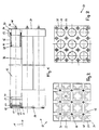
- Fig. 1 eine teilweise aufgeschnittene Seitenansicht eines Katalysatormoduls einer stationären Katalysatoranlage;
- Fig. 2 eine Stirnansicht des Moduls von der Abluftaustrittsseite;
- Fig. 3 eine Stirnansicht des Moduls von der Ablufteintrittsseite;
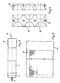
- Fig. 4 eine teilweise aufgeschnittene Ansicht einer Patrone;
- Fig. 5 eine teilweise detaillierte Ansicht des Innenmantels der Patrone;
- Fig. 6 eine Ansicht eines mehrteiligen Klemmstücks;
- Fig. 7 eine aufgeschnittene Ansicht einer mobilen Katalysatoranlage mit einem Katalysatoreinsatz;
- Fig. 8 einen Radialschnitt bei VIII - VIII in Fig. 7;
- Fig. 9 einen Katalysatoreinsatz für Fig. 7;
- Fig. 10 der stromab liegende Patronenhalter von Fig. 9;
- Fig. 11 der stromauf liegende Patronenhalter von Fig. 9;
- Fig. 12 ein Klemmstück des Katalysatoreinsatzes nach Fig. 9;
- Fig. 13 einen Axialschnitt durch eine Filterpatrone im Bereich der Eintrittsseite;
- Fig. 14 das Prinzip einer Vollstrom-Abluftreinigungsanlage;
- Fig. 15 das Prinzip einer Teilstrom-Abluftreinigungsanlage.
- Figure 1 is a partially cutaway side view of a catalyst module of a stationary catalyst system.
- 2 shows an end view of the module from the exhaust air outlet side;
- 3 shows an end view of the module from the exhaust air inlet side;
- Fig. 4 is a partially cutaway view of a cartridge;
- Fig. 5 is a partially detailed view of the inner shell of the cartridge;
- 6 is a view of a multi-part clamping piece;
- 7 shows a cut-away view of a mobile catalytic converter system with a catalytic converter insert;
- 8 shows a radial section at VIII-VIII in FIG. 7;
- FIG. 9 shows a catalyst insert for FIG. 7;
- Fig. 10 shows the downstream cartridge holder of Fig. 9;
- Fig. 11 shows the upstream cartridge holder of Fig. 9;
- FIG. 12 shows a clamping piece of the catalyst insert according to FIG. 9;
- 13 shows an axial section through a filter cartridge in the region of the inlet side;
- 14 shows the principle of a full-flow exhaust air purification system;
- Fig. 15 shows the principle of a partial flow exhaust air cleaning system.
Ein Katalysatormodul 10 einer stationären Katalysatoranlage
gemäss Fig.1 bis 3 ist im wesentlichen quaderförmig ausgebildet,
es hat einen Querschnitt von 150 x 150 mm und eine
Länge von 1000 mm. Ein Modul umfasst neun Patronen 12 mit einem
formfesten Innenmantel 14 eines Durchmessers von etwa 34
mm und einen Aussenmantel 16 aus einem geflochtenen anorganischen
Fasermaterial, welches strumpfförmig über den Innenmantel
14 gezogen ist.A
Die Patronen 12 sind bezüglich eines Abluftstroms 18 stromab
mit einer Verschlusskappe 20 versehen. Der Abgasstrom 18
tritt in den Innenraum 28 der stromauf offenen Patronen 12
ein und gelangt über den porösen Innenmantel 14 und den faserförmigen
Aussenmantel 16 in den Innenraum 26 zwischen den
Patronen 12. Die gereinigte Abluft 18 strömt durch Oeffnungen
im Patronenhalter 24 aus. Am Eintrittsende der stromauf
offenen Patronen 12 ist über eine Klemmbride 34 eine koaxiale
Flanschhülse 30 befestigt. Die Hülse 30 durchgreift entsprechend
dimensionierte Öffnungen 36 im stromauf liegenden Filterpatronenhalter
38. Verschlusskappe 20 und Flanschhülse
30 sind durch Punktschweissen mit dem Innenmantel verbunden,
also nicht gasdicht. Die Abdichtung erfolgt durch je eine
stirnseitige Klemmbride 34, welche auf den Aussenmantel 16
aufgesetzt und im Bereich der Verschlusskappe 20 und der
Flanschhülse 30 angezogen werden.The
Innenseitig ist ein mehrteiliges Klemmstück 40, 42, welches
in Fig. 6 im Detail dargestellt ist, mit dem Patronenhalter 38
verschraubt, die Verschraubung ist mit 56 bezeichnet. Dieses
Klemmstück dient der eintrittsseitigen Abdichtung des Innenraums
26 um die Patronen 12 und damit der Verhinderung von
Leckströmen. Die Dichtungen sind mit 44, 46 bezeichnet.On the inside is a
Stromab ist die Verschlusskappe 20 der Patronen 12 über einen
Gewindebolzen 48 und eine entsprechende Schraubenmutter 50
am Patronenhalter 24 befestigt. Schliesslich wird die Formstabilität
des Katalysatormoduls 10 noch weiter verbessert,
indem der Patronenhalter 24 einen nach innen umgelegten Rand
52, der Patronenhalter 38 einen umgelegten Rand 54 hat. Beim
Stapeln von Modulen 10 bilden die umgelegten Ränder 52, 54
die Auflageflächen.Downstream is the
Auf der in Fig.2 dargestellten Ausströmseite des Katalysatormoduls
10 ist der schalenförmige Patronenhalter 24 mit im
wesentlichen quadratischen Aussparungen versehen. Die über
die Verschlusskappen 20 stirnseitig verschraubten Patronen
lassen stromab einen Innenraum 26 frei, welcher dank den Öffnungen
22 problemlos von der gereinigten Abluft durchströmt
wird. On the outflow side of the catalyst module shown in FIG
10 is the bowl-shaped
Im stromauf liegenden Patronenhalter 38 gemäss Fig. 3 sind
neben den Öffnungen 36 für den Innenmantel der Patronen die
Verschraubungen 56 für das Klemmstück 40, 42 sichtbar.3 are located in the
Der in Fig. 4 gekürzt dargestellte Innenmantel 14 einer Patrone
12 (Fig.1) umfasst am stromabseitigen Ende die Verschlusskappe
20 mit einem Schweissbolzen 48, welcher als
Gewindestange ausgebildet ist. Am stromaufseitigen Ende des
Innenmantels 14 ist eine Flanschhülse 30, auch Kragen genannt,
aufgezogen und mit dem Innenmantel punktverschweisst.The
Fig. 5 zeigt den ausgebreiteten, ebenfalls verkürzt dargestellten
Innenmantel 14 gemäss Fig. 4. Die Porosität besteht
in regelmässig angeordneten Rundlöchern 58, welche über den
ganzen Innenmantel 14 verteilt sind. Die Rundlöcher 58 haben
im vorliegenden Fall einen Durchmesser von 5 mm und einen
allseitigen Abstand d von 7 mm. So gewährleistet die hexagonale
Lochung eine hinreichende mechanische Stabilität zum
Tragen des faserförmigen Aussenmantels 16 (Fig.1).Fig. 5 shows the spread, also shown shortened
Das mehrteilige Klemmstück, von welchem je ein End- und Mittelstück
40, 42 dargestellt sind, weist gemäss Fig. 6 im wesentlichen
halbkreisförmige Aussparungen 60 auf, welche
insgesamt der Anzahl von aufzunehmenden Patronen entsprechen.
Die Aussparungen 60 haben einen etwa 1 mm grösseren
Radius als die Flanschhülse 30. Weiter sind Schraubenlöcher
62 vorgesehen, welche der Befestigung am stromauf liegenden
Patronenhalter 38 (Fig. 1,3) dienen.The multi-part clamping piece, of which one end and one
Fig. 7,8 zeigen eine mobile Katalysatoranlage 66 mit einem in
einem Katalysatorgehäuse 68 angeordneten entfernbaren Katalysatoreinsatz
70. Das Gehäuse ist in eine dieses umgebende
Isolationsschicht 76 eingebettet. Eine stationäre Katalysatoranlage
im Sinne von Fig. 7,8 kann anstelle eines Katalysatoreinsatzes
70 eine beliebige Anzahl von Katalysatormodulen
gemäss Fig. 1 enthalten.7,8 show a mobile
Der zu reinigende Abluftstrom 18 fliesst über einen angeflanschten
Gaszufuhrstutzen 90 in das Katalysatorgehäuse 68
in den Bereich des Katalysatoreinsatzes 70, welcher in Fig. 9
im Detail gezeigt ist. Stromab ist ein Gasabfuhrstutzen 78 am
Katalysatorgehäuse 68 angeflanscht.The
Benachbart des Gasabfuhrstutzens 78 durchgreift ein Rohr 92
mit Kabelhülle die Isolationsschicht 76 und das Katalysatorgehäuse
68. Es dient der Einführung einer Messonde und ist
bei Nichtgebrauch verschlossen.A
In Fig. 8 ist ein Radialschnitt VII-VII gemäss Fig. 7 dargestellt.
Der Katalysatoreinsatz 70 umfasst neunzehn Patronen
12 mit Innenmantel 14 und Aussenmantel 16. Das Katalysatorgehäuse
68 mit der Isolationsschicht 76 ist von einem Spannring
94 umgeben, welcher mit einer Verschraubung 96 feststellbar
ist.FIG. 8 shows a radial section VII-VII according to FIG. 7.
The catalyst insert 70 comprises nineteen
In Fig. 8 ist auch beispielhaft dargestellt, dass innerhalb
des Innenmantels 14 stabförmige Elektrodenelemente zur Anregung
der Dämpfe und Gase mittels elektrischer Felder angeordnet
sein können.In Fig. 8 is also shown as an example that within
of the
Der in Fig. 9 dargestellte Katalysatoreinsatz 70 entspricht
im wesentlichen einem Katalysatormodul 10 gemäss Fig. 1. Bei
sechseckiger Gestaltung der den Aussenumfang bildenden Patronenhalter
24, 38 bzw. von deren umgelegten Rändern 52, 54
(Fig. 1) wird der Katalysatoreinsatz 70 zum Katalysatormodul
10 mit neunzehn Patronen 12. Die vorderste Patrone 12 der
mittleren Ebene ist in voller Grösse sichtbar, die übrigen
sind teilweise verdeckt.The catalyst insert 70 shown in FIG. 9 corresponds
essentially a
Bei einem grösseren Abluftvolumenstrom kann der Katalysatoreinsatz 70 durch Anlegen weiterer Kränze von Patronen vergrössert werden. Aus mechanischen und statischen Gründen muss für einen Katalysatoreinsatz eine Grenze für die Anzahl von Patronen festgelegt werden, der Katalysatoreinsatz wird durch mehrere Katalysatormodule ersetzt.With a larger exhaust air volume flow, the catalyst can be used 70 by creating more wreaths of cartridges be enlarged. For mechanical and static reasons there must be a limit to the number of catalyst applications be determined by cartridges, the catalyst insert replaced by several catalyst modules.
Der Patronenhalter 24 gemäss Fig. 10 auf der Austrittsseite
entspricht im wesentlichen Fig. 2. Wegen der hexagonalen
Struktur des Katalysatoreinsatzes 70 sind die Öffnungen 22
jedoch dreieckförmig ausgebildet. Die neunzehn Löcher 98
dienen der Aufnahme von Gewindebolzen 48 (Fig. 4) zur Befestigung
der nicht dargestellten Patronen. Analog entspricht
der Patronenhalter 38 gemäss Fig. 11 der vorstehenden Fig. 3.
Die zahlreichen Löcher 100 dienen der Befestigung eines
mehrteiligen Klemmstücks.The
Ein dem Patronenhalter 38 auf der Eintrittsseite zugeordnetes
Klemmstück gemäss Fig. 12 ist fünfteilig ausgebildet.
Die beiden endständigen Klemmstücke 40 haben auf ihrer geraden
Längsseite drei im wesentlichen halbkreisförmige Aussparungen
60, welche einen etwa 1 mm grösseren Radius als die
Flanschhülsen 30 (Fig. 4) haben. Die vier mittleren Klemmstücke
41 haben auf ihren Längsseiten drei bis fünf entsprechende
halbkreisförmige Aussparungen 60. Zwischen den
Klemmstücken 40, 41 ist jeweils ein etwa 1 mm breiter Schlitz
104 ausgespart. Die Anordnung der Löcher 100 für die Verschraubungen
56 (Fig. 1,9) entspricht exakt derjenigen des
stromauf angeordneten Patronenhalters 38.One assigned to the
Fig. 13 zeigt eine Variante der Abdichtung des Innenraums 26
(Fig. 1,2) ausserhalb der Patronen in einem Katalysatormodul
oder Katalysatoreinsatz. Benachbart der Stirnseite weist
der Innenmantel 14 eine punktgeschweisste Flanschhülse 30
auf. Ein an dieser Flanschhülse stirnseitig anliegendes
Klemmstück 40, 42 drückt beim Anziehen der Schrauben 56 ( Fig.
1,9) die Flanschhülse 30 gegen die Dichtung 44 und den Patronenhalter
38. Die Patronen 12 müssen also nicht mit einer
Dichtung im Patronenhalter 38 gehaltert sein. 13 shows a variant of the sealing of the interior 26
(Fig. 1,2) outside the cartridges in a catalyst module
or catalyst insert. Adjacent to the face
the
Bei einer Vollstrom-Abluftreinigungsanlage 110 tritt gemäss
Fig. 14 die mit Kohlenwasserstoffen beladene Abluft über
eine Ablufteinlassöffnung 112 und einen Vetilator 114 in
einen Behandlungsraum 116 ein. In diesem Behandlungsraum 116
ist ein Katalysator 118 angeordnet, welcher als die erfindungsgemäße Vorrichtung ausgebildet ist. Vor dem Eintritt in den
Katalysator 118 kann die Abluft über ein an den Behandlungsraum
16 angeschlossenes Heissluftgebläse 120 vorgewärmt
werden. Nach dem Austritt aus dem Katalysator 118 verlässt
die gereinigte Abluft den Behandlungsraum 116 über eine
Reinluftauslassöffnung 122.In a full flow exhaust
Eine in Fig. 15 dargestellte Teilstrom-Abluftreinigungsanlage
130 weist eine Ablufteinlassöffnung 132 sowie einen
daran anschliessenden Ventilator 134 auf. In eine Behandlungsraum
136 ist ein Katalysator 138 angeordnet, welcher als die erfindungsgemäße Vorrichtung ausgebildet ist. An den Behandlungsraum
136 ist zur Abluftvorwärmung ein Heissluftgebläse
140 dem Katalysator 138 vorgeschaltet. Die Abluft mündet
hier zunächst in einen Adsorptionsspeicher 144, in welchem
Kohlenmonoxid oder Kohlenwasserstoffe adsorbiert werden.
Die derart gereinigte Abluft verlässt den Adsorptionsspeicher
144 über die Reinluftauslassöffnung 142. Bei genügender
Beladung des Adsorptionsspeichers 144 werden die Kohlenwasserstoffe
durch Einleitung eines Desorptionsgases
über eine Desorptionsleitung 146 mittels eines Kompressors
148 desorbiert, über das Heissluftgebläse 140 ggf. erwärmt
und anschliessend dem Katalysator 138 zugeführt. Nach dem
Durchtritt durch den Katalysator 138 wird die gereinigte
Abluft über eine Verbindungsleitung 150 zur Reinluftauslassöffnung
142 geführt.A partial flow exhaust air purification system shown in FIG. 15
130 has an exhaust
Die erfindungsgemässe Vorrichtung wirkt selektiv besonders gut für CO ab ca. 150°C und je nach Temperaturbereich und aktiven Material der Patronen gut für CmHn.The device according to the invention acts selectively particularly well for CO from approximately 150 ° C. and, depending on the temperature range and active material of the cartridges, well for C m H n .
Claims (12)
- A device for exhaust air purification of gaseous and vaporous substances, having a housing (68) through which an exhaust air stream (18) flows, with several cartridges (12) which are closed at one end running axially at a distance and have a dimensionally stable, perforated inner jacket (14) and an outer jacket (16) designed to be gas-permeable with a low resistance as a carrier with an active material for catalysis, adsorption or conversion of pollutants in gas, where the cartridges (12) are connected at the gas inlet side to a first cartridge holder (38) which is open in the area of the cartridges (12), and they are also detachably connected at the gas outlet side to a second cartridge holder (24) which is open in the area between the cartridges (12),
characterized in that the cartridges (12) are combined into at least one insert (70) or modules (10) that can be removed from the housing (68),the cartridges (12) are detachably attached individually in the insert (70) or module (10), andsealing means (40, 42, 44) are provided for sealing the interior space (28) of the cartridge in the area of the first cartridge holder (38) with respect to the space (26) outside the respective cartridge (12). - A device according to Claim 1, characterized in that the cartridges (12) with the carriers for catalysis, adsorption and conversion of organic dusts and aerosols in the gas are arranged in separate housings (68) or units.
- A device according to Claim 1 or 2, characterized in that the outer jacket (16) is made of or coated with an active material.
- A device according to one of Claims 1 through 3, characterized in that the cartridges (12) are encompassed upstream by a preferably multipart clamping piece (40, 42) with a tolerance, said clamping piece acting on a gasket (44) placed between the clamping piece (40, 42) and the cartridge holder (38) and sealing the interior space (26) outside the cartridges (12).
- A device according to Claim 4, characterized in that the clamping piece (40, 42) is designed essentially in a strip, with essentially semicircular recesses (60) for the cartridges (12).
- A device according to one of Claims 1 through 5, characterized in that a sealing cap (20) inverted over the inner jacket (14) of the cartridges (12) serves to fasten the cartridges (12) downstream, and upstream a flange sleeve (30) serves to fasten the cartridges, with the sealing cap (20) and the flange sleeve (30) preferably being attached to the inner jacket (14) by spot welding.
- A device according to Claim 6, characterized in that the outer jacket (16) is attached with an airtight seal to the sealing cap (20) and the flange sleeve (30) with strap clamps (34).
- A device according to one of Claims 1 through 7, characterized in that the holding and supporting parts, in particular the inner jacket (14) of the cartridges (12) and the cartridge holders (24, 28) are made of a high-alloy steel.
- A device according to one of Claims 1 through 8, characterized in that the inner jacket (14) of the cartridges (12) has round holes (58) and/or elongated holes or is designed as a wire mesh or a band grid.
- A device according to one of Claims 1 through 9, characterized in that the active material consists of a single-substance coating or a mixture of noble metals or noble metal oxides, in particular platinum, rhodium, palladium, vanadium, cobalt or the oxides thereof with other metals or the oxides thereof.
- A device according to one of Claims 1 through 10, characterized in that the carrier or the outer jacket (16) of the cartridges (12) consists of fibers, in particular knit, woven or braided fibers of activated carbon, ceramic or glass.
- A device according to one of Claims 1 through 11, characterized in that the modules (10) are sealed with respect to one another by an elastic glass cloth seal.
Applications Claiming Priority (4)
| Application Number | Priority Date | Filing Date | Title |
|---|---|---|---|
| CH190/95 | 1995-01-24 | ||
| CH19095 | 1995-01-24 | ||
| CH19095 | 1995-01-24 | ||
| PCT/CH1996/000033 WO1996023134A1 (en) | 1995-01-24 | 1996-01-24 | Device for removing substances in gas and vapour form in a stream of exhaust air |
Publications (2)
| Publication Number | Publication Date |
|---|---|
| EP0805915A1 EP0805915A1 (en) | 1997-11-12 |
| EP0805915B1 true EP0805915B1 (en) | 2000-03-22 |
Family
ID=4181307
Family Applications (1)
| Application Number | Title | Priority Date | Filing Date |
|---|---|---|---|
| EP96900497A Expired - Lifetime EP0805915B1 (en) | 1995-01-24 | 1996-01-24 | Device for removing substances in gas and vapour form in a stream of exhaust air |
Country Status (5)
| Country | Link |
|---|---|
| EP (1) | EP0805915B1 (en) |
| AT (1) | ATE191061T1 (en) |
| AU (1) | AU4429496A (en) |
| DE (1) | DE59604776D1 (en) |
| WO (1) | WO1996023134A1 (en) |
Cited By (1)
| Publication number | Priority date | Publication date | Assignee | Title |
|---|---|---|---|---|
| DE102010053452A1 (en) * | 2010-12-06 | 2012-06-06 | Mann + Hummel Gmbh | Filter unit for exhaust aftertreatment of internal combustion engines |
Families Citing this family (1)
| Publication number | Priority date | Publication date | Assignee | Title |
|---|---|---|---|---|
| JP4032902B2 (en) * | 2002-09-25 | 2008-01-16 | トヨタ自動車株式会社 | Substrate for exhaust purification and method for manufacturing the same |
Citations (1)
| Publication number | Priority date | Publication date | Assignee | Title |
|---|---|---|---|---|
| WO1993003112A1 (en) * | 1991-08-02 | 1993-02-18 | Ronald Peter Hansen | Solution for watering plant roots |
Family Cites Families (9)
| Publication number | Priority date | Publication date | Assignee | Title |
|---|---|---|---|---|
| US3847574A (en) * | 1973-03-14 | 1974-11-12 | American Air Filter Co | Charcoal filter arrangement |
| US3969095A (en) * | 1973-08-25 | 1976-07-13 | Shigeru Kurahashi | Air filter apparatus |
| US4018568A (en) * | 1976-02-09 | 1977-04-19 | Uop Inc. | Fume absorbing-treating system |
| DE3007639A1 (en) * | 1980-02-29 | 1981-09-17 | Daimler-Benz Ag, 7000 Stuttgart | IC engine exhaust gas filter with renewable cartridge - has filter material around perforated tubes between end-plates one of which has outlet holes |
| DE3823205A1 (en) * | 1988-07-08 | 1990-01-11 | Eberspaecher J | Soot-filter plug for the purification of exhaust gases and soot-filter arrangement formed from soot-filter plugs |
| JPH04500777A (en) * | 1989-07-12 | 1992-02-13 | ジンテルメタルウエルク・クレープゼーゲ・ゲゼルシャフト・ミト・ベシュレンクテル・ハフツング | Permeable porous body for treating gas and/or vapor and/or liquid and method for producing the same |
| US5258164A (en) * | 1991-04-05 | 1993-11-02 | Minnesota Mining And Manufacturing Company | Electrically regenerable diesel particulate trap |
| WO1994021351A1 (en) * | 1993-03-17 | 1994-09-29 | Massachusetts Institute Of Technology | Active filters for integrated cleanup of gas streams |
| NO932152L (en) * | 1993-06-11 | 1994-12-12 | Abb Miljoe Norsk Viftefab | Adsorption |
-
1996
- 1996-01-24 AU AU44294/96A patent/AU4429496A/en not_active Abandoned
- 1996-01-24 DE DE59604776T patent/DE59604776D1/en not_active Expired - Fee Related
- 1996-01-24 AT AT96900497T patent/ATE191061T1/en not_active IP Right Cessation
- 1996-01-24 WO PCT/CH1996/000033 patent/WO1996023134A1/en active IP Right Grant
- 1996-01-24 EP EP96900497A patent/EP0805915B1/en not_active Expired - Lifetime
Patent Citations (1)
| Publication number | Priority date | Publication date | Assignee | Title |
|---|---|---|---|---|
| WO1993003112A1 (en) * | 1991-08-02 | 1993-02-18 | Ronald Peter Hansen | Solution for watering plant roots |
Cited By (1)
| Publication number | Priority date | Publication date | Assignee | Title |
|---|---|---|---|---|
| DE102010053452A1 (en) * | 2010-12-06 | 2012-06-06 | Mann + Hummel Gmbh | Filter unit for exhaust aftertreatment of internal combustion engines |
Also Published As
| Publication number | Publication date |
|---|---|
| WO1996023134A1 (en) | 1996-08-01 |
| EP0805915A1 (en) | 1997-11-12 |
| ATE191061T1 (en) | 2000-04-15 |
| DE59604776D1 (en) | 2000-04-27 |
| AU4429496A (en) | 1996-08-14 |
Similar Documents
| Publication | Publication Date | Title |
|---|---|---|
| EP0633065B1 (en) | Process for the cleaning of exhaust air containing noxious substances by heterogeneous catalysis | |
| DE4290489C2 (en) | Exhaust gas purification system for a diesel engine and method for regenerating ceramic filters | |
| DE4420224C2 (en) | Process for removing undesirable gas admixtures | |
| EP0979135A1 (en) | Device and method for decomposing harmful substances contained in flue gas | |
| DE3538155A1 (en) | METHOD FOR THE OXIDATION OF PARTICLES DEPOSED IN SOOT FILTERING SYSTEMS | |
| DE10238770A1 (en) | Device for removing soot particles from the exhaust gas of a diesel engine | |
| DE4026375C1 (en) | ||
| EP0603986B1 (en) | Device for cleaning exhaust air containing noxious substances | |
| EP0561484B1 (en) | Process and apparatus for the cleaning of exhaust air cointaining noxious substances by heterogeneous catalysis | |
| EP0805915B1 (en) | Device for removing substances in gas and vapour form in a stream of exhaust air | |
| CH689687A5 (en) | Soot filter for waste gas cleaning, especially for soot particle removal from diesel engine exhaust gases filter inserts or modules fitted with detachable filter cartridges | |
| WO1988009865A1 (en) | Exhaust gas cleaning device for diesel engines | |
| WO1992019849A1 (en) | Filter device and process for cleaning exhaust gases by filtration | |
| DE19717890C1 (en) | Silent discharge from selectively-doped, porous silicon carbide electrode, treating variety of flue- and exhaust gases | |
| DE19652403B4 (en) | Device and method for oxidative exhaust gas purification | |
| DE1907027C3 (en) | Device for treating a compound in the gas phase on a solid | |
| EP0342588B1 (en) | Method and apparatus for purifying exhaust gases with honey comb bodies made of calcium compounds | |
| DE19651822C2 (en) | Process for reducing the PCDD and / or PCDF concentration in exhaust gases | |
| EP1358923B1 (en) | Particle or hybrid filter, in particular for the treatment of air to be introduced in a vehicle passenger compartment | |
| EP3185993A1 (en) | Treatment device and method for treating an exhaust stream | |
| CN215138255U (en) | Green chemical waste gas treatment device | |
| DE4213822A1 (en) | Internal combustion engine exhaust gas filter | |
| DE19815004C1 (en) | Catalytic purification of flue gases | |
| DE10126665A1 (en) | Automotive fuel cell, for use in gas filter system, comprises cold start-up droplet separator, adsorbent unit and oxidation stage within single housing | |
| DE19720981A1 (en) | Gas filter |
Legal Events
| Date | Code | Title | Description |
|---|---|---|---|
| PUAI | Public reference made under article 153(3) epc to a published international application that has entered the european phase |
Free format text: ORIGINAL CODE: 0009012 |
|
| 17P | Request for examination filed |
Effective date: 19970725 |
|
| AK | Designated contracting states |
Kind code of ref document: A1 Designated state(s): AT CH DE FR GB IT LI NL SE |
|
| 17Q | First examination report despatched |
Effective date: 19980108 |
|
| GRAG | Despatch of communication of intention to grant |
Free format text: ORIGINAL CODE: EPIDOS AGRA |
|
| GRAG | Despatch of communication of intention to grant |
Free format text: ORIGINAL CODE: EPIDOS AGRA |
|
| GRAH | Despatch of communication of intention to grant a patent |
Free format text: ORIGINAL CODE: EPIDOS IGRA |
|
| GRAH | Despatch of communication of intention to grant a patent |
Free format text: ORIGINAL CODE: EPIDOS IGRA |
|
| GRAA | (expected) grant |
Free format text: ORIGINAL CODE: 0009210 |
|
| AK | Designated contracting states |
Kind code of ref document: B1 Designated state(s): AT CH DE FR GB IT LI NL SE |
|
| REF | Corresponds to: |
Ref document number: 191061 Country of ref document: AT Date of ref document: 20000415 Kind code of ref document: T |
|
| REG | Reference to a national code |
Ref country code: CH Ref legal event code: EP |
|
| REF | Corresponds to: |
Ref document number: 59604776 Country of ref document: DE Date of ref document: 20000427 |
|
| ITF | It: translation for a ep patent filed |
Owner name: ING. PIOVESANA PAOLO |
|
| GBT | Gb: translation of ep patent filed (gb section 77(6)(a)/1977) |
Effective date: 20000519 |
|
| ET | Fr: translation filed | ||
| PLBE | No opposition filed within time limit |
Free format text: ORIGINAL CODE: 0009261 |
|
| STAA | Information on the status of an ep patent application or granted ep patent |
Free format text: STATUS: NO OPPOSITION FILED WITHIN TIME LIMIT |
|
| PG25 | Lapsed in a contracting state [announced via postgrant information from national office to epo] |
Ref country code: GB Free format text: LAPSE BECAUSE OF NON-PAYMENT OF DUE FEES Effective date: 20010124 Ref country code: AT Free format text: LAPSE BECAUSE OF NON-PAYMENT OF DUE FEES Effective date: 20010124 |
|
| PG25 | Lapsed in a contracting state [announced via postgrant information from national office to epo] |
Ref country code: SE Free format text: LAPSE BECAUSE OF NON-PAYMENT OF DUE FEES Effective date: 20010125 |
|
| 26N | No opposition filed | ||
| PGFP | Annual fee paid to national office [announced via postgrant information from national office to epo] |
Ref country code: CH Payment date: 20010430 Year of fee payment: 6 |
|
| PG25 | Lapsed in a contracting state [announced via postgrant information from national office to epo] |
Ref country code: NL Free format text: LAPSE BECAUSE OF NON-PAYMENT OF DUE FEES Effective date: 20010801 |
|
| PGFP | Annual fee paid to national office [announced via postgrant information from national office to epo] |
Ref country code: DE Payment date: 20010831 Year of fee payment: 6 |
|
| EUG | Se: european patent has lapsed |
Ref document number: 96900497.7 |
|
| GBPC | Gb: european patent ceased through non-payment of renewal fee |
Effective date: 20010124 |
|
| NLV4 | Nl: lapsed or anulled due to non-payment of the annual fee |
Effective date: 20010801 |
|
| PG25 | Lapsed in a contracting state [announced via postgrant information from national office to epo] |
Ref country code: LI Free format text: LAPSE BECAUSE OF NON-PAYMENT OF DUE FEES Effective date: 20020131 Ref country code: CH Free format text: LAPSE BECAUSE OF NON-PAYMENT OF DUE FEES Effective date: 20020131 |
|
| PG25 | Lapsed in a contracting state [announced via postgrant information from national office to epo] |
Ref country code: FR Free format text: LAPSE BECAUSE OF NON-PAYMENT OF DUE FEES Effective date: 20020329 |
|
| REG | Reference to a national code |
Ref country code: FR Ref legal event code: ST |
|
| PG25 | Lapsed in a contracting state [announced via postgrant information from national office to epo] |
Ref country code: DE Free format text: LAPSE BECAUSE OF NON-PAYMENT OF DUE FEES Effective date: 20020801 |
|
| REG | Reference to a national code |
Ref country code: CH Ref legal event code: PL |
|
| PG25 | Lapsed in a contracting state [announced via postgrant information from national office to epo] |
Ref country code: IT Free format text: LAPSE BECAUSE OF NON-PAYMENT OF DUE FEES;WARNING: LAPSES OF ITALIAN PATENTS WITH EFFECTIVE DATE BEFORE 2007 MAY HAVE OCCURRED AT ANY TIME BEFORE 2007. THE CORRECT EFFECTIVE DATE MAY BE DIFFERENT FROM THE ONE RECORDED. Effective date: 20050124 |
|
| PG25 | Lapsed in a contracting state [announced via postgrant information from national office to epo] |
Ref country code: FR Free format text: LAPSE BECAUSE OF NON-PAYMENT OF DUE FEES Effective date: 20010131 |