EP0805570A1 - Digital phase locked loop for clock recovery - Google Patents
Digital phase locked loop for clock recovery Download PDFInfo
- Publication number
- EP0805570A1 EP0805570A1 EP97400949A EP97400949A EP0805570A1 EP 0805570 A1 EP0805570 A1 EP 0805570A1 EP 97400949 A EP97400949 A EP 97400949A EP 97400949 A EP97400949 A EP 97400949A EP 0805570 A1 EP0805570 A1 EP 0805570A1
- Authority
- EP
- European Patent Office
- Prior art keywords
- frequency
- signal
- clock
- divider
- phase
- Prior art date
- Legal status (The legal status is an assumption and is not a legal conclusion. Google has not performed a legal analysis and makes no representation as to the accuracy of the status listed.)
- Withdrawn
Links
Images
Classifications
-
- H—ELECTRICITY
- H04—ELECTRIC COMMUNICATION TECHNIQUE
- H04J—MULTIPLEX COMMUNICATION
- H04J3/00—Time-division multiplex systems
- H04J3/02—Details
- H04J3/06—Synchronising arrangements
- H04J3/07—Synchronising arrangements using pulse stuffing for systems with different or fluctuating information rates or bit rates
- H04J3/073—Bit stuffing, e.g. PDH
-
- H—ELECTRICITY
- H03—ELECTRONIC CIRCUITRY
- H03L—AUTOMATIC CONTROL, STARTING, SYNCHRONISATION, OR STABILISATION OF GENERATORS OF ELECTRONIC OSCILLATIONS OR PULSES
- H03L7/00—Automatic control of frequency or phase; Synchronisation
- H03L7/06—Automatic control of frequency or phase; Synchronisation using a reference signal applied to a frequency- or phase-locked loop
- H03L7/08—Details of the phase-locked loop
- H03L7/099—Details of the phase-locked loop concerning mainly the controlled oscillator of the loop
- H03L7/0991—Details of the phase-locked loop concerning mainly the controlled oscillator of the loop the oscillator being a digital oscillator, e.g. composed of a fixed oscillator followed by a variable frequency divider
- H03L7/0992—Details of the phase-locked loop concerning mainly the controlled oscillator of the loop the oscillator being a digital oscillator, e.g. composed of a fixed oscillator followed by a variable frequency divider comprising a counter or a frequency divider
Landscapes
- Engineering & Computer Science (AREA)
- Computer Networks & Wireless Communication (AREA)
- Signal Processing (AREA)
- Stabilization Of Oscillater, Synchronisation, Frequency Synthesizers (AREA)
- Synchronisation In Digital Transmission Systems (AREA)
Abstract
Description
Le domaine de l'invention est celui des dispositifs de génération de signaux d'horloge et concerne plus particulièrement un dispositif destiné à récupérer un rythme d'horloge à partir d'une horloge de référence dans laquelle des transitions sont absentes. Le dispositif de l'invention doit notamment être apte à récupérer des horloges de fréquences différentes, c'est à dire présenter une fonctionalité multi-débits.The field of the invention is that of devices for generating clock signals and relates more particularly to a device intended to recover a clock rhythm from a reference clock in which transitions are absent. The device of the invention must in particular be capable of recovering clocks of different frequencies, that is to say having a multi-bit rate functionality.
On se placera dans la suite de cette description dans le cadre d'un système de transmission, par exemple par faisceaux hertziens, où les données numériques sont transmises dans des trames plésiochrones. Chaque trame véhicule une pluralité de communications et un récepteur de ces trames réalise un démultiplexage des données reçues afin de les appliquer sur différentes voies correspondant chacune à un destinataire différent. A chaque voie correspond une fréquence d'horloge.We will place ourselves in the rest of this description within the framework of a transmission system, for example by radio-relay systems, where the digital data are transmitted in plesiochronous frames. Each frame carries a plurality of communications and a receiver of these frames demultiplexes the received data in order to apply them on different channels, each corresponding to a different recipient. Each channel has a clock frequency.
En fait, les données de chaque voie, à la sortie du système de démultiplexage, sont synchronisées par une horloge à trous, c'est à dire dans laquelle des transitions sont absentes, pour leur écriture dans une mémoire tampon. Ces trous viennent de la justification lors du multiplexage émission, de l'absence des autres voies, et de l'insertion dans la trame de bits d'information (mot de verrouillage de trame, bits de parité, code correcteur d'erreur, etc.). Afin de permettre une relecture correcte des données reçues, il est nécessaire de régénérer une horloge exempte de trous, c'est à dire présentant des transitions régulières. On utilise pour cela habituellement une boucle à verrouillage de phase destinée à fournir une horloge régulière, de même fréquence que la fréquence moyenne de cette horloge à trous, pour lire les données stockées temporairement dans la mémoire tampon.In fact, the data of each channel, at the output of the demultiplexing system, are synchronized by a clock with holes, that is to say in which transitions are absent, for their writing in a buffer memory. These holes come from the justification during transmission multiplexing, from the absence of the other channels, and from the insertion in the frame of information bits (frame locking word, parity bits, error correcting code, etc. .). In order to allow correct reading of the data received, it is necessary to regenerate a clock free of holes, that is to say having regular transitions. For this, a phase-locked loop is usually used to provide a regular clock, of the same frequency as the average frequency of this hole clock, to read the data temporarily stored in the buffer memory.
On considérera dans la suite de cette description trois débits de transmission différents (1,544 Mbits/s, 2,048 Mbits/s et 8,448 Mbits/s), et donc 3 fréquences d'horloge à récupérer différentes. Les précisions des horloges à récupérer sont, dans le système considéré, de ±50 ppm pour les débits de 1,544 Mbits/s et 2,048 Mbits/s et de ±30 ppm pour le débit de 8,448 Mbits/s.In the following description, three different transmission rates will be considered (1.544 Mbits / s, 2.048 Mbits / s and 8.448 Mbits / s), and therefore 3 different clock frequencies to be recovered. The details of the clocks to be recovered are, in the system considered, ± 50 ppm for the bit rates of 1.544 Mbits / s and 2.048 Mbits / s and ± 30 ppm for the bit rates of 8.448 Mbits / s.
L'invention propose une solution numérique plutôt qu'analogique pour la réalisation de la fonction de récupération d'horloge pour des raisons de modularité, de réutilisabilité (composants reprogrammables), d'intégration et de coût (implantable dans des circuits ASICs).The invention proposes a digital rather than analog solution for the realization of the clock recovery function for reasons of modularity, reusability (reprogrammable components), integration and cost (implantable in ASICs circuits).
La présente invention vise notamment à respecter les recommandations du CCITT suivantes : G823 (ou G824 pour les débits américains) concernant la gigue maximale admissible à une interface hiérarchique, G921 concernant la gigue résiduelle, G703 sur les précisions des horloges et les gabarits des impulsions, G751 pour le multiplexage/démultiplexage aux débits tramés de 34,368 Mbits/s (soit 4*8,448 Mbits/s) avec justification positive pour le transfert de gigue, G742 pour le multiplexage/démultiplexage au débit 2,048 Mbits/s avec justification positive pour le transfert de gigue et G743 pour le multiplexage/démultiplexage du débit d'affluent de 1,544 Mbits/s pour le transfert de gigue.The present invention aims in particular to comply with the following CCITT recommendations: G823 (or G824 for American bit rates) concerning the maximum jitter admissible at a hierarchical interface, G921 concerning residual jitter, G703 on the precision of clocks and pulse templates, G751 for multiplexing / demultiplexing at framed bit rates of 34.368 Mbits / s (i.e. 4 * 8.448 Mbits / s) with positive justification for jitter transfer, G742 for multiplexing / demultiplexing at bit rates 2.048 Mbits / s with positive justification for transfer and G743 for multiplexing / demultiplexing the tributary rate of 1.544 Mbits / s for jitter transfer.
On connaît, par la demande de brevet européen n°0.471.506, un dispositif numérique apte à régénérer un signal d'horloge régulier à partir d'une horloge trouée. Cependant, ce dispositif ne fonctionne que si l'horloge à récupérer est une horloge synchrone du signal transmis et suppose que l'horloge à régénérer est une fraction rationnelle de l'horloge trouée. Ce dispositif ne convient donc pas pour un système de transmission plésiochrone où les différents affluents ont chacun leur propre horloge.We know from European patent application No. 0.471.506 a digital device capable of regenerating a regular clock signal from a clock with a gap. However, this device only works if the clock to be recovered is a synchronous clock of the transmitted signal and assumes that the clock to be regenerated is a rational fraction of the broken clock. This device is therefore not suitable for a plesiochronous transmission system where the different tributaries each have their own clock.
La présente invention a notamment pour objectif de pallier cet inconvénient.The object of the present invention is in particular to overcome this drawback.
Plus précisément, la présente invention a pour objectif de fournir un dispositif destiné à fournir une horloge régulière, appelée horloge récupérée, dont la fréquence est égale à la fréquence moyenne de l'horloge à trous (horloge de référence) dans un système plésiochrone.More specifically, the present invention aims to provide a device intended to provide a regular clock, called a recovered clock, the frequency of which is equal to the average frequency of the hole clock (reference clock) in a plesiochronous system.
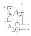
Cet objectif, ainsi que d'autres qui apparaîtront par la suite, est atteint grâce à une boucle à verrouillage de phase numérique du type fournissant un signal d'horloge, appelé horloge récupérée, à partir d'un signal d'horloge de référence dans lequel des transitions sont absentes, appelé horloge trouée et de fréquence Fref, cette boucle comportant :
- un premier diviseur de fréquence par M recevant l'horloge trouée et fournissant un signal de fréquence Fref/M ;
- un comparateur de phase à deux entrées, l'une des entrées recevant le signal de fréquence Fref/M, l'autre des entrées recevant le signal de sortie d'un deuxième diviseur de fréquence par M, le comparateur de phase fournissant un signal d'erreur de phase ;
- un diviseur de fréquence par K d'un signal d'oscillateur local de fréquence FOL recevant comme signal de commande le signal d'erreur de phase et fournissant un signal de fréquence Fk ;
- un additionneur-accumulateur recevant le signal d'oscillateur local de fréquence FOL et fournissant un signal de sortie de fréquence F0 égal à FOL*p/q avec p/q le rapport de division de l'additionneur-accumulateur ;
- un mélangeur recevant le signal de fréquence Fk et le signal de fréquence F0, le mélangeur fournissant un signal de fréquence Fn égal à F0-Fk ;
- un diviseur de fréquence par N synchronisé par FOL recevant le signal de fréquence Fn et fournissant l'horloge récupérée au deuxième diviseur de fréquence par M.
- a first frequency divider by M receiving the gap clock and providing a frequency signal F ref / M;
- a phase comparator with two inputs, one of the inputs receiving the frequency signal F ref / M, the other of the inputs receiving the output signal of a second frequency divider by M, the phase comparator providing a signal phase error;
- a frequency divider by K of a local oscillator signal of frequency F OL receiving as control signal the phase error signal and supplying a signal of frequency F k ;
- an adder-accumulator receiving the local oscillator signal of frequency F OL and providing an output signal of frequency F 0 equal to F OL * p / q with p / q the division ratio of the adder-accumulator;
- a mixer receiving the signal of frequency F k and the signal of frequency F 0 , the mixer supplying a signal of frequency F n equal to F 0 -F k ;
- a frequency divider by N synchronized by F OL receiving the frequency signal F n and supplying the clock recovered to the second frequency divider by M.
Avantageusement, un diviseur de fréquence par T est inséré entre le mélangeur et le diviseur de fréquence par N.Advantageously, a frequency divider by T is inserted between the mixer and the frequency divider by N.
Le comparateur de phase est préférentiellement constitué par une porte Ou-Exclusif.The phase comparator is preferably constituted by an Or-Exclusive gate.
D'autres caractéristiques et avantages de l'invention apparaîtront à la lecture de la description suivante d'un mode de réalisation préférentiel, donné à titre illustratif et non limitatif, et de la figure unique annexée représentant un schéma synoptique de la boucle à verrouillage de phase selon l'invention.Other characteristics and advantages of the invention will appear on reading the following description of a preferred embodiment, given by way of illustration and not limitation, and of the single appended figure representing a block diagram of the locking loop of phase according to the invention.
La boucle à verrouillage de phase selon l'invention, généralement référencée par 10, reçoit un signal d'horloge de référence de fréquence Fref dans lequel des transitions sont absentes. Cette horloge peut être qualifiée d'horloge trouée. La boucle 10 fournit un signal d'horloge Frec, appelé horloge récupérée, à partir de l'horloge de référence Fref et d'un signal d'oscillateur local de fréquence FOL. La fréquence FOL est par exemple au moins 8 fois supérieure à la fréquence de l'horloge récupérée Frec, afin de respecter la norme G823 à 8 Mbits/s. La valeur du rapport FOL/Frec dépend en fait essentiellement des performances voulues pour la gigue mesurée sur l'horloge récupérée. La taille de la mémoire tampon (constituée par exemple par une FIFO) dépend essentiellement de la gigue sur l'horloge de référence causée par les trous du démultiplexage et donc essentiellement de la structure de trame utilisée.The phase locked loop according to the invention, generally referenced by 10, receives a reference clock signal of frequency F ref in which transitions are absent. This clock can be called a clock with a hole. The
L'horloge trouée de fréquence Fref est appliquée à un premier diviseur de fréquence par M, référencé 11 et fournissant un signal de fréquence Fref/M. De même, l'horloge récupérée de fréquence Frec et issue d'un diviseur par N référencé 18, est appliquée à un deuxième diviseur de fréquence par M, référencé 12 et fournissant un signal de fréquence Frec/M. Les signaux de fréquence Fref/M et Frec/M sont appliqués à un comparateur de phase 13 à deux entrées, constitué ici par une porte Ou-Exclusif ou par une bascule D dans un autre mode de réalisation. On ne considérera dans la suite de cette description que la réalisation du comparateur de phase sous la forme d'une porte Ou-Exclusif.The clock with frequency F ref is applied to a first frequency divider by M, referenced 11 and providing a signal of frequency F ref / M. Likewise, the recovered clock of frequency F rec and coming from a divider by N referenced 18, is applied to a second frequency divider by M, referenced 12 and providing a frequency signal F rec / M. The frequency signals F ref / M and F rec / M are applied to a
La comparaison de phase est donc réalisée entre l'horloge de référence et l'horloge récupérée divisées par M. Cette division permet de réduire la gigue à l'entrée de la boucle, qui est causée par les trous de l'horloge de référence : la gigue haute fréquence est filtrée et la taille des trous par rapport à la période de comparaison est diminuée. Il est en effet important, pour que la boucle reste verrouillée, de limiter l'erreur de phase à la plage de synchronisation du comparateur de phase et de rester dans son mode de fonctionnement linéaire. Dans ce cas, la gigue maximale du signal de comparaison est de 1 IU crête-à-crête, IU étant la durée nominale qui sépare deux instants significatifs consécutifs d'un signal isochrone. La gigue maximale de l'horloge de référence divisée par M est de 0,5 IU avec le Ou-Exclusif comme comparateur de phase.The phase comparison is therefore carried out between the reference clock and the recovered clock divided by M. This division makes it possible to reduce the jitter at the input of the loop, which is caused by the holes in the reference clock: the high frequency jitter is filtered and the size of the holes with respect to the comparison period is reduced. It is indeed important, in order for the loop to remain locked, to limit the phase error to the synchronization range of the phase comparator and to remain in its linear operating mode. In this case, the maximum jitter of the comparison signal is 1 IU peak-to-peak, IU being the nominal duration which separates two consecutive significant instants of an isochronous signal. The maximum jitter of the reference clock divided by M is 0.5 IU with the Or-Exclusive as the phase comparator.
Il est avantageux d'utiliser un comparateur de phase constitué par un Ou-Exclusif car ce type de comparateur est adapté aux signaux ayant un rapport cyclique de 1/2 (cas des signaux d'horloge divisés par M), il présente un gain Kd égal à 1/π et sa réalisation sous la forme d'un ASIC est simple.It is advantageous to use a phase comparator constituted by an Exclusive Or because this type of comparator is suitable for signals having a duty cycle of 1/2 (case of clock signals divided by M), it has a gain K d equal to 1 / π and its realization in the form of an ASIC is simple.
Pour lire la mémoire tampon, on utilise tous les bits à droite du bit de poids le plus fort si le comparateur de phase est un Ou-Exclusif : ainsi les poids forts des adresses d'écriture et de lecture sont en opposition de phase. La taille de la mémoire tampon est donc liée à M car, lorsque la boucle est accrochée, la sortie du comparateur de phase a un rapport cyclique de 1/2.To read the buffer memory, all the bits to the right of the most significant bit are used if the phase comparator is an Or-Exclusive: thus the most significant of the write and read addresses are in phase opposition. The size of the buffer memory is therefore linked to M because, when the loop is hooked, the output of the phase comparator has a duty cycle of 1/2.
Le signal d'erreur de phase issu du comparateur 13 constitue un signal de commande appliqué à un diviseur de fréquence par K, référencé 14. La valeur moyenne du signal de sortie du comparateur de phase est proportionnelle à l'erreur de phase. Le diviseur de fréquence 14 reçoit en outre un signal d'oscillateur local de fréquence FOL et fournit un signal de fréquence Fk.The phase error signal from the
La fréquence Fk est comprise entre 0 Hz et FOL/K. Ainsi, lorsque la boucle est verrouillée à la fréquence centrale fc (de fréquence égale au débit de l'horloge à récupérer), le signal de commande du compteur K contient autant de 1 que 0, et donc Fk = FOL/2K. La fréquence récupérée minimale correspond alors à Fk = Fkmin = 0 Hz, et la fréquence maximale à Fk = Fkmax = FOL/K. Pour que la boucle reste accrochée, il faut que la fréquence Fk nécessaire pour recaler Frec sur Fref soit comprise entre Fkmin et Fkmax et que la gigue de FK causée par les trous de l'horloge de référence ne fassent pas sortir Fk de ces limites.The frequency F k is between 0 Hz and F OL / K. Thus, when the loop is locked at the central frequency f c (of frequency equal to the flow of the clock to be recovered), the control signal of the counter K contains as much 1 as 0, and therefore F k = F OL / 2K . The minimum recovered frequency corresponds then at F k = F kmin = 0 Hz, and the maximum frequency at F k = F kmax = F OL / K. For the loop to remain hooked, the frequency F k necessary to readjust F rec on F ref must be between F kmin and F kmax and the jitter of F K caused by the holes in the reference clock should not get F k out of these limits.
La plage d'accrochage de la boucle est d'autant plus grande que la valeur de K est petite. En revanche, le réglage de Frec est d'autant plus fin que la valeur de K est grande. Il y a donc un compromis à trouver. En pratique, il faudra vérifier que la plage d'accrochage est nettement supérieure à ±30 ppm ou ±50 ppm selon le débit, en tenant compte de la précision de FOL. De plus, il faudra qu'à des valeurs limites, les proportions d'états logiques 0 et 1 du signal de commande soient le plus proche possible de 50 %, afin de disposer d'un rapport cyclique de 1/2. Ainsi la largeur admise des trous de l'horloge de référence Fref sera d'autant plus grande.The smaller the hooking range of the loop, the smaller the value of K. On the other hand, the setting of F rec is all the more fine the larger the value of K. So there is a compromise to be found. In practice, it will be necessary to check that the attachment range is clearly greater than ± 30 ppm or ± 50 ppm depending on the flow rate, taking into account the precision of F OL . Furthermore, at limit values, the proportions of logic states 0 and 1 of the control signal must be as close as possible to 50%, in order to have a duty cycle of 1/2. Thus the admitted width of the holes of the reference clock F ref will be all the greater.
Le signal de fréquence Fk issu du diviseur 14 est appliqué à un mélangeur 15 recevant par ailleurs un signal de fréquence fixe F0 d'un additionneur-accumulateur 16 à l'entrée duquel est appliqué le signal de fréquence FOL. Le mélangeur 15 fournit un signal de sortie de fréquence F0-Fk.The frequency signal F k from the
L'additionneur-accumulateur 16 fournit le signal de fréquence F0 égal à FOL*p/q avec p/q le rapport de division de l'additionneur-accumulateur 16.The adder-
Le signal de fréquence F0-Fk issu du mélangeur 15 est appliqué éventuellement à un diviseur de fréquence par T, référencé 17, facultatif et dont la fonction sera explicitée par la suite.The frequency signal F 0 -F k from the
Le signal issu du mélangeur 15 (ou celui issu du diviseur par T référencé 17) est appliqué à un diviseur de fréquence par N, référencé 18. Le signal d'entrée de ce diviseur 18 est noté Fn et correspond soit à F0-Fk, soit à (F0-Fk)/T. Le diviseur 18 est synchronisé par FOL et fournit l'horloge récupérée de fréquence Frec au deuxième diviseur de fréquence par M, référencé 12.The signal from the mixer 15 (or that from the divider by T referenced 17) is applied to a frequency divider by N, referenced 18. The input signal from this
Le diviseur 18 par N est synchronisé par FOL (c'est à dire que le comptage est réalisé par FOL et interrompu à la fréquence Fn).The
Le diviseur par T référencé 17 fonctionne avec T = 2 ou T = 4. Ce diviseur a été introduit pour diminuer l'amplitude de gigue résiduelle.The divider by T referenced 17 works with T = 2 or T = 4. This divider has been introduced to reduce the amplitude of residual jitter.
Les variations de F0 peuvent être réduites en choisissant une valeur de p petite. De plus, les variations les plus importantes de Fn sont causées par les interruptions à la fréquence Fk ; à la fréquence moyenne Fk, on supprime un front d'horloge de F0, la période est alors doublée instantanément. Le diviseur par T divise par T l'amplitude de cette gigue.The variations of F 0 can be reduced by choosing a small p value. In addition, the largest variations in F n are caused by interruptions at the frequency F k ; at the average frequency F k , we remove a clock face of F 0 , the period is then doubled instantly. The divider by T divides by T the amplitude of this jitter.
L'étude théorique de la boucle selon l'invention est réalisée ci-après :The theoretical study of the loop according to the invention is carried out below:
Comme indiqué précédemment, la valeur moyenne du signal de sortie du comparateur de phase 13, notée ![]()
![]()
![]()
![]()
La fréquence du signal de sortie du diviseur 14 s'écrit donc :![]()
![]()
Et on a également :![]()
![]()
![]()
![]()
La fréquence récupérée s'écrit donc :![]()
![]()
En entrée du comparateur de phase, on a f1 = Fref/M et f2 = Frec/M.Φe = f1-f2. D'où :
Le passage dans le plan complexe donne :![]()
![]()
![]()
![]()
La fréquence de coupure du système est donc égale à :![]()
![]()
La plage d'accrochage de la boucle s'écrit :
![]()
![]()
D'où:![]()
![]()
![]()
![]()
La plage d'accrochage théorique est définie par :![]()
![]()
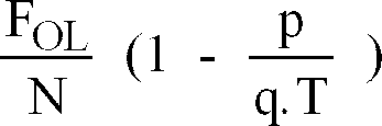
La fréquence centrale de la boucle est :![]()
![]()
![]()
![]()
![]()
![]()
La plage d'accrochage théorique de la boucle est indépendante du type de comparateur, tant que l'erreur de phase en entrée est dans sa plage de synchronisation. Lorsque l'horloge de référence est entachée de trous, la plage d'accrochage réelle est plus petite ; la boucle se déverrouille lorsque la fréquence de référence sort de la plage d'accrochage ou lorsqu'elle subit des variations trop rapides vis-à-vis du temps de réponse du système.The theoretical hooking range of the loop is independent of the type of comparator, as long as the input phase error is within its synchronization range. When the reference clock is tainted with holes, the real latching range is smaller; the loop is unlocked when the reference frequency leaves the latching range or when it undergoes too rapid variations with respect to the system response time.
Afin d'augmenter la plage d'accrochage en présence de trous, on peut augmenter le rang du diviseur par M. On réduit ainsi la gigue du signal de comparaison de phase, on diminue la fréquence de coupure de la boucle et on augmente son temps de réponse. Le système filtre alors mieux la gigue de l'horloge de référence, mais le temps d'accrochage est plus long. On a donc intérêt à choisir M le plus petit possible, d'autant plus que la taille de la mémoire tampon est liée à M.In order to increase the latching range in the presence of holes, the rank of the divider can be increased by M. This reduces the jitter of the phase comparison signal, we reduce the cutoff frequency of the loop and we increase its time Answer. The system then filters the jitter of the reference clock better, but the hanging time is longer. It is therefore advantageous to choose M as small as possible, especially since the size of the buffer memory is linked to M.
Lorsque la fréquence de référence Fref est différente de sa valeur nominale, le signal de comparaison à l'équilibre a des proportions de 1 et de 0 différentes. Le système admet alors moins de gigue sur l'horloge de référence : si par exemple, la position d'équilibre correspond à 60% d'états logiques 1 et à 40% d'états logiques 0, la gigue maximale du signal de comparaison devient alors 2*0,4 = 0,8 IU crête-à-crête, au lieu de 1 IU. Plus la plage d'accrochage est grande, plus les proportions d'états logiques 1 et 0 aux valeurs limites de Fref seront proches, et plus la gigue admise sur le signal de comparaison de phase sera proche de 1 IU.When the reference frequency F ref is different from its nominal value, the equilibrium comparison signal has different proportions of 1 and 0. The system then admits less jitter on the reference clock: if for example, the equilibrium position corresponds to 60% of logic states 1 and to 40% of logic states 0, the maximum jitter of the comparison signal becomes then 2 * 0.4 = 0.8 IU peak-to-peak, instead of 1 IU. The larger the hooking range, the closer the proportions of logic states 1 and 0 to the limit values of F ref , and the closer the jitter admitted on the phase comparison signal will be to 1 IU.
Le choix de la valeur de M dépend donc de la structure de trame et du temps de réponse du système, c'est-à-dire de sa fonction de transfert. Il y a compromis à trouver, car le temps de réponse du système augmente avec M, créant un équilibre moins stable, tandis que sa fréquence de coupure diminue, permettant un meilleur filtrage des perturbations sur l'horloge de référence. Si on augmente la largeur des trous de l'horloge de référence, il faut augmenter la plage d'accrochage de la boucle, et éventuellement la valeur de M et la taille de la mémoire tampon.The choice of the value of M therefore depends on the frame structure and the response time of the system, that is to say on its transfer function. There is a compromise to be found, because the system response time increases with M, creating a less stable equilibrium, while its cut-off frequency decreases, allowing better filtering of disturbances on the reference clock. If the width of the holes in the reference clock is increased, the hooking range of the loop must be increased, and possibly the value of M and the size of the buffer.
La gigue de l'horloge récupérée provient essentiellement des variations du rang de division du compteur N. On peut la quantifier en étudiant les variations de la fréquence d'interruption du compteur : Fn ![]()
![]()
La valeur de N est choisie de la manière suivante :![]()
![]()
On a donc Fn = Fol - N*Fc < Fc et le compteur N est interrompu soit 0 soit 1 fois par période de l'horloge récupérée.We therefore have F n = F ol - N * F c <F c and the counter N is interrupted either 0 or 1 time per period of the recovered clock.
Les valeurs extrêmes de Fn sont :![]()
![]()
![]()
![]()
La période de l'horloge récupérée est donc constitué de N ou N+1 périodes de Fol. L'amplitude de la gigue résiduelle observée sur l'horloge récupérée est donc de l'ordre d'une période de Fol, soit environ 1/N IU crête-à-crête.The period of the recovered clock therefore consists of N or N + 1 periods of F ol . The amplitude of the residual jitter observed on the recovered clock is therefore of the order of a period of F ol , ie approximately 1 / N IU peak-to-peak.
Le pas de sortie est la valeur minimale de variation de la fréquence lorsque le rang de division du compteur K change d'une unité. Ce pas de sortie est noté P et vaut :![]()
![]()
On remarque que K doit être assez grand pour un pas de sortie raisonnable (quelques Hz). On préférera aussi une grande valeur de N.Note that K must be large enough for a reasonable output step (a few Hz). We also prefer a large value of N.
On note τ le pourcentage de niveaux logiques '1' du signal issu du comparateur de phase 13. La valeur de τ est :![]()
![]()
La valeur minimale de τ (notée τmin) est obtenue pour FOL_max et τmax vaut 1-τmin.The minimum value of τ (noted τ min ) is obtained for F OL_max and τ max is 1-τ min .
La boucle décrite jusqu'ici est applicable non seulement aux trois débits mentionnés mais également à d'autres débits, notamment lorsque la gigue de l'horloge récupérée est importante.The loop described so far is applicable not only to the three rates mentioned but also to other rates, especially when the jitter of the clock recovered is significant.
Plus précisément, la fréquence centrale de la boucle est entièrement programmable grâce :
- au choix de N qui permet d'approcher Fc selon la relation

- au choix de l'additionneur-accumulateur (et de T) qui permet d'approcher plus finement la fréquence Fc. La fréquence Fc est légèrement supérieure à :
- la contribution de Fk plus ou moins grande selon l'erreur de phase, de valeur faible par rapport à l'horloge récupérée (de l'ordre de 50-100 kHz). Plus la fréquence Fk est importante (K petit), plus la boucle d'accrochage de la boucle est importante. En revanche, l'horloge récupérée est plus sensible aux variations de l'erreur de phase : la fréquence de coupure de la boucle est d'autant plus grande que K est petit.
- choice of N which allows to approach F c according to the relation
- at the choice of the adder-accumulator (and of T) which allows the frequency F c to be approached more finely. The frequency F c is slightly higher than:
- the contribution of F k more or less large according to the phase error, of low value compared to the recovered clock (of the order of 50-100 kHz). The higher the frequency F k (K small), the greater the hooking loop of the loop. On the other hand, the recovered clock is more sensitive to variations in the phase error: the cutoff frequency of the loop is all the greater the smaller K is.
Les valeurs des paramètres dépendent d'abord du rapport FOL/Frec : ce rapport fournit, à partir de la relation 1, une valeur entière de N à partir de laquelle est déterminé la plus petite valeur de Fn possible. A partir de Fn, on détermine ensuite les valeurs de K, T et p/q en notant que plus la fréquence Fk est importante, plus la plage d'accrochage est grande mais aussi plus la gigue est importante.The values of the parameters depend first of all on the ratio F OL / F rec : this ratio provides, from relation 1, an integer value of N from which the lowest possible value of F n is determined. From F n , the values of K, T and p / q are then determined, noting that the greater the frequency F k , the larger the gripping range but also the greater the jitter.
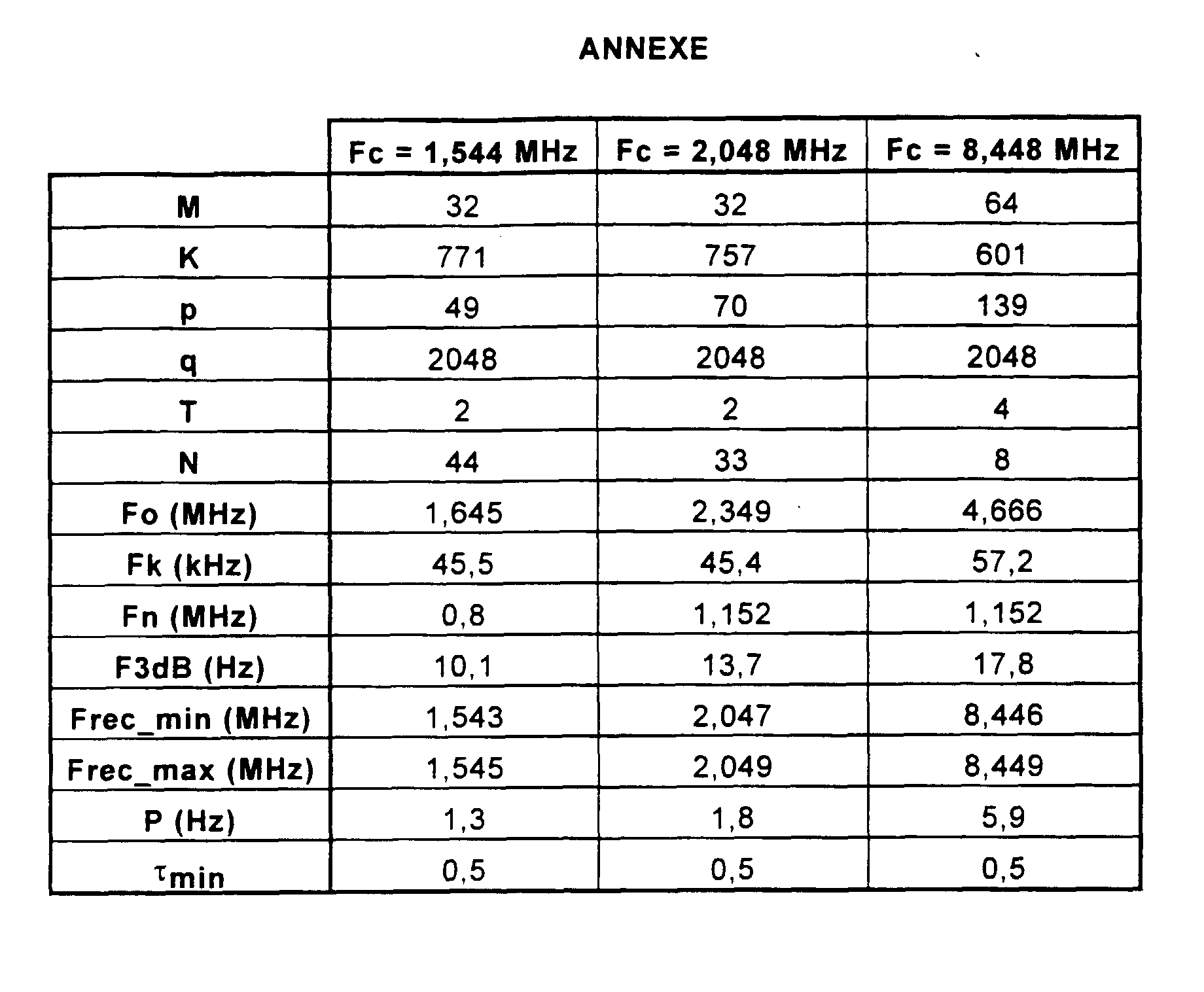
Une application numérique de l'invention est donnée dans le tableau en annexe. On considère les trois débits de transmission précités (1,544 Mbits/s, 2,048 Mbits/s et 8,448 Mbits/s), et donc 3 fréquences d'horloge à récupérer différentes pour les choix de M, K, p, q, N et éventuellement T, avec un comparateur de phase constitué par un Ou-Exclusif. La valeur de FOL est de 68,736 MHz.A digital application of the invention is given in the table in the appendix. We consider the three aforementioned transmission rates (1.544 Mbits / s, 2.048 Mbits / s and 8.448 Mbits / s), and therefore 3 different clock frequencies to be recovered for the choices of M, K, p, q, N and possibly T, with a phase comparator constituted by an Exclusive-Or. The value of F OL is 68.736 MHz.
Dans le tableau, la profondeur de la mémoire tampon est de 16 bits (M=32) pour les débits de 1,544 Mhz et 2,048 Mhz et de 32 bits (M=64) pour le débit de 8,448 Mhz. La profondeur de l'additionneur-accumulateur est de 11 bits. Le choix de M dépend de la structure de trame, comme cela a été décrit précédemment.In the table, the buffer depth is 16 bits (M = 32) for bit rates of 1.544 Mhz and 2.048 Mhz and 32 bits (M = 64) for bit rates of 8.448 Mhz. The depth of the adder-accumulator is 11 bits. The choice of M depends on the frame structure, as described above.
Dans le cadre d'une application spécifique, le trou le plus grand de l'horloge de référence est causé par un mot de verrouillage de trame de 12 bits, le débit tramé est de 9,874 Mhz et la fréquence de l'horloge à récupérer est de 8,448 Mhz. Dans ce cas, la gigue maximale de l'horloge trouée est de (12/9,874) * 8,448 ≈ 10 IU crête-à-crête rapportés à la fréquence de l'horloge récupérée à 8,448 Mhz. La gigue causée par ce trou sur le signal de comparaison de phase est d'environ 10/M, soit environ 0,31 IU pour M = 32 et 0,16 IU pour M = 64. Il faut donc prendre τmin > 0,31 pour M = 32 et τmin > 0,16 pour M = 64.In the context of a specific application, the largest hole in the reference clock is caused by a 12-bit frame alignment word, the framed bit rate is 9.874 Mhz and the frequency of the clock to be recovered is of 8.448 Mhz. In this case, the maximum jitter of the gap clock is (12 / 9.874) * 8.448 ≈ 10 IU peak-to-peak related to the frequency of the clock recovered at 8.448 Mhz. The jitter caused by this hole in the phase comparison signal is approximately 10 / M, ie approximately 0.31 IU for M = 32 and 0.16 IU for M = 64. We must therefore take τ min > 0, 31 for M = 32 and τ min > 0.16 for M = 64.
Des essais ont permis de vérifier le bon fonctionnement de la boucle selon l'invention lorsque la fréquence de référence varie de ±30 ppm autour de sa valeur nominale, pour le débit 8,448 Mbits/s, et de ±50ppm pour les autres débits. La boucle reste accrochée à ces fréquences. Elle fonctionne aussi avec une précision de l'oscillateur local de ±50 ppm. La plage d'accrochage mesurée est inférieure à la plage théorique, en raison des trous de l'horloge de référence.Tests have made it possible to verify the proper functioning of the loop according to the invention when the reference frequency varies by ± 30 ppm around its nominal value, for the bit rate 8.448 Mbits / s, and by ± 50ppm for the other bit rates. The loop remains attached to these frequencies. It also works with a local oscillator accuracy of ± 50 ppm. The measured grip range is less than the theoretical range, due to the holes in the reference clock.
La boucle à verrouillage de phase de l'invention est notamment implantable en ASIC.
Claims (3)
Applications Claiming Priority (2)
| Application Number | Priority Date | Filing Date | Title |
|---|---|---|---|
| FR9605496 | 1996-05-02 | ||
| FR9605496A FR2748361B1 (en) | 1996-05-02 | 1996-05-02 | DIGITAL PHASE LOCKED LOOP FOR CLOCK RECOVERY |
Publications (1)
| Publication Number | Publication Date |
|---|---|
| EP0805570A1 true EP0805570A1 (en) | 1997-11-05 |
Family
ID=9491769
Family Applications (1)
| Application Number | Title | Priority Date | Filing Date |
|---|---|---|---|
| EP97400949A Withdrawn EP0805570A1 (en) | 1996-05-02 | 1997-04-28 | Digital phase locked loop for clock recovery |
Country Status (4)
| Country | Link |
|---|---|
| US (1) | US5937021A (en) |
| EP (1) | EP0805570A1 (en) |
| CA (1) | CA2204275A1 (en) |
| FR (1) | FR2748361B1 (en) |
Families Citing this family (3)
| Publication number | Priority date | Publication date | Assignee | Title |
|---|---|---|---|---|
| US7161998B2 (en) * | 2001-01-24 | 2007-01-09 | Broadcom Corporation | Digital phase locked loop for regenerating the clock of an embedded signal |
| US20070140399A1 (en) * | 2005-12-20 | 2007-06-21 | International Business Machines Corporation | Phase-locked loop |
| WO2008001811A1 (en) * | 2006-06-29 | 2008-01-03 | Nippon Telegraph And Telephone Corporation | Cdr circuit |
Citations (3)
| Publication number | Priority date | Publication date | Assignee | Title |
|---|---|---|---|---|
| DE2023656A1 (en) * | 1970-05-14 | 1971-12-02 | Deutsche Bundespost | Method for the recovery of the plesiochronous primary clocks at the receiving end of a plurality of primary time multiplexing systems combined at the transmitting end to form a time multiple of a higher order |
| US4803680A (en) * | 1985-12-27 | 1989-02-07 | Nec Corporation | Destuffing circuit with a digital phase-locked loop |
| AU604997B2 (en) * | 1988-02-26 | 1991-01-03 | Alcatel Australia Limited | A digital phase locked loop |
Family Cites Families (7)
| Publication number | Priority date | Publication date | Assignee | Title |
|---|---|---|---|---|
| US3781695A (en) * | 1972-05-04 | 1973-12-25 | Westinghouse Electric Corp | Digital phase-locked-loop |
| JPH07336342A (en) * | 1994-06-13 | 1995-12-22 | Fujitsu Ltd | Clock reproducing circuit |
| JP2964916B2 (en) * | 1995-05-31 | 1999-10-18 | 日本電気株式会社 | Digital phase locked loop circuit and data receiving circuit using the same |
| JP2817676B2 (en) * | 1995-07-31 | 1998-10-30 | 日本電気株式会社 | PLL frequency synthesizer |
| JP2850949B2 (en) * | 1995-12-15 | 1999-01-27 | 日本電気株式会社 | Digital PLL device |
| US5793825A (en) * | 1996-03-04 | 1998-08-11 | Motorola, Inc. | Method and apparatus for extending an operating frequency range of an instantaneous phase-frequency detector |
| US5825253A (en) * | 1997-07-15 | 1998-10-20 | Qualcomm Incorporated | Phase-locked-loop with noise shaper |
-
1996
- 1996-05-02 FR FR9605496A patent/FR2748361B1/en not_active Expired - Lifetime
-
1997
- 1997-04-28 EP EP97400949A patent/EP0805570A1/en not_active Withdrawn
- 1997-05-01 US US08/848,742 patent/US5937021A/en not_active Expired - Fee Related
- 1997-05-01 CA CA002204275A patent/CA2204275A1/en not_active Abandoned
Patent Citations (3)
| Publication number | Priority date | Publication date | Assignee | Title |
|---|---|---|---|---|
| DE2023656A1 (en) * | 1970-05-14 | 1971-12-02 | Deutsche Bundespost | Method for the recovery of the plesiochronous primary clocks at the receiving end of a plurality of primary time multiplexing systems combined at the transmitting end to form a time multiple of a higher order |
| US4803680A (en) * | 1985-12-27 | 1989-02-07 | Nec Corporation | Destuffing circuit with a digital phase-locked loop |
| AU604997B2 (en) * | 1988-02-26 | 1991-01-03 | Alcatel Australia Limited | A digital phase locked loop |
Non-Patent Citations (1)
| Title |
|---|
| YOSHINORI ROKUGO ET AL: "A DIGITAL PHASE-LOCKED LOOP FOR STUFFING SYNCHRONIZATION SYSTEMS", ELECTRONICS & COMMUNICATIONS IN JAPAN, PART I - COMMUNICATIONS, vol. 75, no. 4, 1 April 1992 (1992-04-01), pages 1 - 12, XP000307927 * |
Also Published As
| Publication number | Publication date |
|---|---|
| US5937021A (en) | 1999-08-10 |
| CA2204275A1 (en) | 1997-11-02 |
| FR2748361B1 (en) | 1998-06-05 |
| FR2748361A1 (en) | 1997-11-07 |
Similar Documents
| Publication | Publication Date | Title |
|---|---|---|
| FR2498032A1 (en) | BIT SYNCHRONIZER FOR DIGITAL SIGNALS | |
| EP0419337B1 (en) | Digital signal encoding method, encoder and decoder for carrying out the method, regeneration method and regenerator therefore | |
| EP0013990B1 (en) | Serial binary information transmission method and devices for implementing the method | |
| CA2046241C (en) | Data serialization and deserialization device and series digital data transmission system using said device | |
| EP0481847B1 (en) | Device for jitter reduction caused by pointer jumps in a digital telecommunication network | |
| EP2345161B1 (en) | Device for reconstructing the clock of an nrz signal, and associated transmission system | |
| EP1049285B1 (en) | Frequency-locked loop | |
| FR2501437A1 (en) | SERIES-PARALLEL CONVERTER | |
| FR2580130A1 (en) | ||
| EP0459911B1 (en) | Procedure of reducing the low frequency component of the jitter in a digital transmission system | |
| EP0716501A1 (en) | Phase comparator of a digital signal and a clock signal, and corresponding phase locked loop | |
| US7123678B2 (en) | RZ recovery | |
| FR2713034A1 (en) | Clock recovery circuit with paired oscillators. | |
| EP0023852A1 (en) | Method and device for adjusting the phase of a local clock | |
| FR2664769A1 (en) | DATA SAMPLING DEVICE AND DATA DIGITAL TRANSMISSION SYSTEM THEREOF. | |
| EP1710916B1 (en) | Phase-locked loop | |
| EP0805570A1 (en) | Digital phase locked loop for clock recovery | |
| EP0396461B1 (en) | Device for synchronising a pseudo-binary signal with a phase-hopped regenerated clock signal | |
| EP0130899A2 (en) | Programmable series/parallel converter circuit for a digital signal, and its use in a receiver for digital video signals | |
| EP0821488B1 (en) | Device for frequency selection comprising a lock detector | |
| FR2858730A1 (en) | Scheduling information recovering method for e.g. Ethernet network, involves using frequency or phase modulated signal for transmitting additional information to recover clock signal, and recovering clock signal using information | |
| EP0605267B1 (en) | Multirate frame and device for multiplexing data of non-multiple bit rates | |
| FR2793623A1 (en) | Sync. for clocks within nodes of digital network includes transmission of internal clock frequency from each node to next for comparison and correction | |
| EP0643502B1 (en) | Circuit for filtering the jitter of positive stuffing in a digital bitstream and the application for filtering the jitter of positive and negative stuffing in a digital bitstream | |
| EP0237408B1 (en) | Method and device for asynchronous clock recovery for digital transmission systems |
Legal Events
| Date | Code | Title | Description |
|---|---|---|---|
| PUAI | Public reference made under article 153(3) epc to a published international application that has entered the european phase |
Free format text: ORIGINAL CODE: 0009012 |
|
| AK | Designated contracting states |
Kind code of ref document: A1 Designated state(s): DE ES FI GB IT SE |
|
| 17P | Request for examination filed |
Effective date: 19980506 |
|
| STAA | Information on the status of an ep patent application or granted ep patent |
Free format text: STATUS: THE APPLICATION HAS BEEN WITHDRAWN |
|
| 18W | Application withdrawn |
Withdrawal date: 20001028 |