EP0805093B1 - Positioning device of a motor vehicle steering column during a shock - Google Patents
Positioning device of a motor vehicle steering column during a shock Download PDFInfo
- Publication number
- EP0805093B1 EP0805093B1 EP97400966A EP97400966A EP0805093B1 EP 0805093 B1 EP0805093 B1 EP 0805093B1 EP 97400966 A EP97400966 A EP 97400966A EP 97400966 A EP97400966 A EP 97400966A EP 0805093 B1 EP0805093 B1 EP 0805093B1
- Authority
- EP
- European Patent Office
- Prior art keywords
- tube
- steering column
- support member
- steering
- impact
- Prior art date
- Legal status (The legal status is an assumption and is not a legal conclusion. Google has not performed a legal analysis and makes no representation as to the accuracy of the status listed.)
- Expired - Lifetime
Links
Images


Classifications
-
- B—PERFORMING OPERATIONS; TRANSPORTING
- B62—LAND VEHICLES FOR TRAVELLING OTHERWISE THAN ON RAILS
- B62D—MOTOR VEHICLES; TRAILERS
- B62D1/00—Steering controls, i.e. means for initiating a change of direction of the vehicle
- B62D1/02—Steering controls, i.e. means for initiating a change of direction of the vehicle vehicle-mounted
- B62D1/16—Steering columns
- B62D1/18—Steering columns yieldable or adjustable, e.g. tiltable
- B62D1/19—Steering columns yieldable or adjustable, e.g. tiltable incorporating energy-absorbing arrangements, e.g. by being yieldable or collapsible
- B62D1/197—Steering columns yieldable or adjustable, e.g. tiltable incorporating energy-absorbing arrangements, e.g. by being yieldable or collapsible incorporating devices for preventing ingress of the steering column into the passengers space in case of accident
Definitions
- the device for positioning, during an impact, a steering column of a motor vehicle is associated with a steering column including a steering shaft, which is mounted to rotate freely in a body tube.
- the body tube is arranged in a support element, which is integral with the chassis of the vehicle.
- the tube body is adjustable in height and depth in the vertical plane, and is locked in the support element by a system for adjusting the position of said steering column.
- the positioning device comprises additional means for guiding the tube-body in the event of impact comprising an additional guide slide on the tube-body, so that the angle of the steering shaft and steering wheel with the horizontal plane, ie weaker after retraction of the steering wheel, to allow operation under optimal conditions of an air bag.
- the additional guide slide is arranged on the reinforcement square of the tube-body, in the extension of a slide for adjusting the depth of the steering column.
- the additional guide slide is inclined with respect to the depth adjustment slide, by an angle which allows operation under optimal conditions of the air bag after retraction.
- the additional guide means consist of an additional guide slide, which is arranged on the support element.
- This additional guide slide comprises two “U” shaped guide elements, which are arranged parallel to each other on the support element so as to be able to receive and maintain a plate carried by the reinforcement square of the tube body. The plate is secured to the two U-shaped guide elements by fuse pins.
- the two guide elements are inclined relative to the support element by an angle, which allows operation under optimal conditions of the air bag after retraction, which is due to the rupture of the fuse pins caused by the shock. .
- This retraction results from the sliding of the plate in the two U-shaped guide elements.
- the cylinder of the pyrotechnic cylinder is mounted on the support element, and the end of the piston rod is connected to the tube-body.
- the positioning device in the event of an impact from a steering column of a motor vehicle according to the invention, thus has the advantage of positioning the steering column at an angle with respect to the horizontal, which is smaller , during an impact, so that the air-bag operates at optimal conditions.
- the invention also has the advantage of making it possible to have an arrangement of the steering column for normal use, which perfectly meets the ergonomic conditions.
- the device of the invention can be adapted and mounted very easily in new architectures or in existing architectures of a motor vehicle steering column.
- the additional guide means consist of an additional guide slide marked 9 which is arranged on the support element 4.
- This additional guide slide 9 on the support element 4 comprises two guide elements in the shape of a "U" 10 and 11, the guide element 10 being arranged at the top and the guide element 11 being arranged at the bottom. These two guide elements 10 and 11 are placed parallel to each other, and are arranged so as to be able to receive and hold a plate 12.
- the plate 12 is carried by the reinforcement square 3 of the tube- body 2 with which it is integral.
- the plate 12 is secured to the two guide elements 10 and 11 in a U shape by fuse pins 13.
- the two guide elements 10 and 11 are inclined relative to the support element 4, by a angle that allows the air bag to operate under optimal conditions, after retraction of the steering column. This retraction is made possible by the rupture of the fuse pins 13, which is caused by the shock.
- the retraction is guided by the sliding of the plate 12 in the two U-shaped guide elements 10 and 11.
Landscapes
- Engineering & Computer Science (AREA)
- Chemical & Material Sciences (AREA)
- Combustion & Propulsion (AREA)
- Transportation (AREA)
- Mechanical Engineering (AREA)
- Steering Controls (AREA)
- Air Bags (AREA)
Description
La présente invention se rapporte a un
dispositif de positionnement en cas de choc, d'une colonne de
direction de véhicule automobile
telle que définie dans les préambules des revendications 1 et 2 et
correspondant à une colonne de direction réglable d'un type bien connu.
L'installation d'une colonne de direction de
véhicule automobile à l'intérieur de l'habitacle,
doit répondre à des critères ergonomiques, qui font
que l'angle de la colonne de direction par rapport à
l'horizontal doit être de l'ordre de 30 degrés. Les
exigences de plus en plus sévères de protection du
conducteur, en cas d'accident, et notamment en cas de
choc frontal, ont amené les constructeurs à prévoir
un système à coussin d'air de sécurité, plus
communément appelé «air-bag», qui se gonfle presque
instantanément, lors d'un choc, afin de protéger le
conducteur en recouvrant le volant. Afin que ce
système agisse dans les meilleures conditions, il est
nécessaire que le volant soit abaissé sur
l'horizontale à un angle inférieur à 20 degrés. Il
existe des dispositifs de guidage en cas de choc avec
une seule rainure comme le document DE-A-3433936, ou
avec une zone de réglage munie d'un canal comme le
document DE-A-4421509.
Dans ces dispositifs connus, l'angle de l'arbre de direction et
du volant avec le plan horizontal est plus faible après
rétraction du volant.
Le but de la présente invention est de proposer
un dispositif de positionnement, en cas de choc,
d'une colonne de direction de véhicule automobile,
qui agisse de manière à ce que l'angle de la colonne
de direction et du volant avec le plan horizontal
soit à la valeur exigée, pour un fonctionnement à des
conditions optimales de l'«air-bag», cet angle étant
différent de l'angle prévu pour l'utilisation
normale. The present invention relates to a device for positioning in the event of an impact, a motor vehicle steering column as defined in the preambles of
The installation of a motor vehicle steering column inside the passenger compartment must meet ergonomic criteria, which means that the angle of the steering column with respect to the horizontal must be order of 30 degrees. The increasingly stringent requirements for driver protection in the event of an accident, and in particular in the event of a frontal impact, have led manufacturers to provide a safety air cushion system, more commonly known as an "air bag". , which inflates almost instantly, upon impact, to protect the driver by covering the steering wheel. In order for this system to operate in the best conditions, it is necessary that the steering wheel is lowered horizontally to an angle less than 20 degrees. There are impact guiding devices with a single groove like the document DE-A-3433936, or with an adjustment zone provided with a channel like the document DE-A-4421509.
In these known devices, the angle of the steering shaft and of the steering wheel with the horizontal plane is smaller after retraction of the steering wheel.
The object of the present invention is to provide a device for positioning, in the event of an impact, a steering column of a motor vehicle, which acts so that the angle of the steering column and of the steering wheel with the plane horizontal or at the required value, for operation under optimal conditions of the "air-bag", this angle being different from the angle provided for normal use.
Selon l'invention, le dispositif de
positionnement, lors d'un choc, d'une colonne de
direction de véhicule automobile est associé à une
colonne de direction incluant un arbre de direction,
qui est monté libre en rotation dans un tube-corps.
Le tube-corps est disposé dans un élément support,
qui est solidaire du châssis du véhicule. Le tube-corps
est réglable en hauteur et en profondeur dans
le plan vertical, et est bloqué dans l'élément
support par un système de réglage en position de
ladite colonne de direction. Dans un premier mode de réalisation de l'invention, le dispositif de
positionnement comprend des moyens de guidage
additionnels du tube-corps en cas de choc comportant
une glissière additionnelle de guidage sur le tube-corps,
de manière que l'angle de l'arbre de direction
et du volant avec le plan horizontal, soit plus
faible après rétraction du volant, afin de permettre
un fonctionnement à des conditions optimales d'un
air-bag. La glissière additionnelle de guidage est
agencée sur le carré renfort du tube-corps, dans le
prolongement d'une glissière de réglage en profondeur
de la colonne de direction. La glissière
additionnelle de guidage est inclinée par rapport à
la glissière de-réglage en profondeur, d'un angle qui
permet un fonctionnement à des conditions optimales
de l'air-bag après rétraction.
Dans une autre réalisation de l'invention, les
moyens de guidage additionnels consistent en une
glissière additionnelle de guidage, qui est agencée
sur l'élément support. Cette glissière additionnelle
de guidage comprend deux éléments de guidage en forme
de «U», qui sont disposés parallèlement l'un par
rapport à l'autre sur l'élément support de manière à
pouvoir recevoir et maintenir une plaque portée par
le carré renfort du tube-corps. La plaque est
solidarisée avec les deux éléments de guidage en
forme de U par des goupilles-fusibles. Les deux
éléments de guidage sont inclinés par rapport à
l'élément support d'un angle, qui permet un
fonctionnement à des conditions optimales de l'air-bag
après rétraction, qui est due à la rupture des
goupilles-fusibles provoquées par le choc. Cette
rétraction résulte du glissement de la plaque dans
les deux éléments de guidage en forme de U.
Dans les réalisations de l'invention, il est
particulièrement intéressant que la colonne de
direction soit rétractée par un vérin pyrotechnique,
qui est piloté par un détecteur de collision. Dans
cette architecture, le cylindre du vérin
pyrotechnique est monté sur l'élément support, et
l'extrémité de la tige du piston est raccordée au
tube-corps.
Le dispositif de positionnement, en cas de choc
d'une colonne de direction d'un véhicule automobile
selon l'invention, présente ainsi l'avantage de
positionner la colonne de direction à un angle par
rapport à l'horizontale, qui soit plus faible, lors
d'un choc, de manière à ce que l'air-bag fonctionne à
des conditions optimales. L'invention présente
également l'avantage de permettre d'avoir une
disposition de la colonne de direction pour
l'utilisation normale, qui réponde parfaitement aux
conditions ergonomiques. Enfin le dispositif de
l'invention peut s'adapter et se monter très
facilement dans de nouvelles architectures ou dans
des architectures existantes de colonne de direction
de véhicule automobile.According to the invention, the device for positioning, during an impact, a steering column of a motor vehicle is associated with a steering column including a steering shaft, which is mounted to rotate freely in a body tube. The body tube is arranged in a support element, which is integral with the chassis of the vehicle. The tube body is adjustable in height and depth in the vertical plane, and is locked in the support element by a system for adjusting the position of said steering column. In a first embodiment of the invention, the positioning device comprises additional means for guiding the tube-body in the event of impact comprising an additional guide slide on the tube-body, so that the angle of the steering shaft and steering wheel with the horizontal plane, ie weaker after retraction of the steering wheel, to allow operation under optimal conditions of an air bag. The additional guide slide is arranged on the reinforcement square of the tube-body, in the extension of a slide for adjusting the depth of the steering column. The additional guide slide is inclined with respect to the depth adjustment slide, by an angle which allows operation under optimal conditions of the air bag after retraction.
In another embodiment of the invention, the additional guide means consist of an additional guide slide, which is arranged on the support element. This additional guide slide comprises two “U” shaped guide elements, which are arranged parallel to each other on the support element so as to be able to receive and maintain a plate carried by the reinforcement square of the tube body. The plate is secured to the two U-shaped guide elements by fuse pins. The two guide elements are inclined relative to the support element by an angle, which allows operation under optimal conditions of the air bag after retraction, which is due to the rupture of the fuse pins caused by the shock. . This retraction results from the sliding of the plate in the two U-shaped guide elements.
In the embodiments of the invention, it is particularly advantageous for the steering column to be retracted by a pyrotechnic cylinder, which is controlled by a collision detector. In this architecture, the cylinder of the pyrotechnic cylinder is mounted on the support element, and the end of the piston rod is connected to the tube-body.
The positioning device, in the event of an impact from a steering column of a motor vehicle according to the invention, thus has the advantage of positioning the steering column at an angle with respect to the horizontal, which is smaller , during an impact, so that the air-bag operates at optimal conditions. The invention also has the advantage of making it possible to have an arrangement of the steering column for normal use, which perfectly meets the ergonomic conditions. Finally, the device of the invention can be adapted and mounted very easily in new architectures or in existing architectures of a motor vehicle steering column.
D'autres caractéristiques et avantages de l'invention ressortiront de la description qui va suivre, donnée à titre d'exemples nullement limitatifs, en référence aux dessins annexés sur lesquels :
- la figure 1 est une vue en coupe partielle, axiale et verticale d'une colonne de direction de véhicule automobile munie d'un dispositif de positionnement selon l'invention, en utilisation normale sans choc ;
- la figure 2 est une vue analogue à la figure 1 après un choc et rétraction de la colonne de direction ;
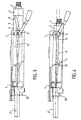
- la figure 3 est une vue analogue à la figure 1 d'un autre mode de réalisation de l'invention en utilisation normale sans choc ;
- la figure 4 est une vue analogue à la figure 3, après un choc et rétraction de la colonne de direction ;
- la figure 5 est une vue analogue à la figure 1, d'un autre mode de réalisation de l'invention en utilisation normale sans choc ;
- la figure 6 est une vue analogue à la figure 5, après un choc et rétraction de la colonne de direction ; et
- la figure 7 est une vue partielle en perspective cavalière correspondante à la figure 5.
- Figure 1 is a partial sectional, axial and vertical view of a motor vehicle steering column provided with a positioning device according to the invention, in normal use without shock;
- Figure 2 is a view similar to Figure 1 after an impact and retraction of the steering column;
- Figure 3 is a view similar to Figure 1 of another embodiment of the invention in normal use without shock;
- Figure 4 is a view similar to Figure 3, after an impact and retraction of the steering column;
- Figure 5 is a view similar to Figure 1, of another embodiment of the invention in normal use without shock;
- Figure 6 is a view similar to Figure 5, after impact and retraction of the steering column; and
- FIG. 7 is a partial view in perspective corresponding to FIG. 5.
Comme on peut le voir sur les différentes
figures, la colonne de direction de véhicule
automobile comporte un arbre de direction 1 qui est
monté libre en rotation dans un tube-corps 2. Le
tube-corps 2 est disposé dans un élément support 4
qui est solidaire du châssis du véhicule automobile.
Le tube-corps 2 est réglable en hauteur et en
profondeur dans le plan vertical, et est bloqué dans
l'élément support par un système de réglage 5 en
position de ladite colonne de direction. As we can see on the different
figures, the vehicle steering column
automobile has a steering shaft 1 which is
mounted free in rotation in a tube-
Selon l'invention, le dispositif de
positionnement, lors d'un choc, d'une colonne de
direction de véhicule automobile comprend des moyens
de guidage additionnels du tube-corps 2. Ces moyens
de guidage additionnels agissent de manière que
l'angle de l'arbre de direction 1 et du volant avec
le plan horizontal, soit plus faible après rétraction
du volant, afin de permettre un fonctionnement
correct et à des conditions optimales d'un coussin
d'air de sécurité. Ce coussin d'air de sécurité est
plus communément appelé air-bag, et c'est le terme
qui sera utilisé dans la suite de la description.According to the invention, the device for
positioning, during an impact, of a column of
motor vehicle steering includes means
additional guide tube-
Dans les réalisations de l'invention
représentées sur les figures 1 à 4, les moyens de
guidage additionnels consistent en une glissière
additionnelle de guidage 8, qui est agencée sur le
tube-corps 2. Plus précisément, la glissière
additionnelle de guidage 8 est agencée sur un carré
renfort 3 solidaire du tube-corps 2. La glissière
additionnelle de guidage 8 est disposée dans le
prolongement de la glissière de réglage en profondeur
6, du système de réglage 5 en position de la colonne
de direction. Le système de réglage en position 5
comporte également une glissière de réglage en
hauteur 7 agencée sur l'élément support 4. Selon la
caractéristique essentielle de l'invention, la
glissière additionnelle de guidage 8 est inclinée par
rapport à la glissière de réglage en profondeur 6
d'un angle qui permet un fonctionnement correct de
l'air-bag sous des conditions optimales après
rétraction de la colonne de direction.
La position de la colonne de direction après
rétraction et choc est représentée clairement sur les
figures 2 et 4 où peut être vue la nouvelle position
en inclinaison par rapport à l'horizontale de la
colonne de direction.
Dans la réalisation de l'invention représentée
sur les figures 3 et 4, la colonne de direction est
rétractée par un vérin pyrotechnique 20, qui est
piloté par un détecteur de collision. Dans cette
réalisation, le cylindre 21 du vérin pyrotechnique 20
est monté sur l'élément support 4, et l'extrémité 22
de la tige du piston est raccordée au tube-corps 2.
Lors d'un choc à une valeur prédéterminée, le
détecteur de collision pilote le vérin pyrotechnique,
de manière à envoyer le gaz généré par l'explosion
sur le piston pour manoeuvrer le tube-corps 2.
Dans la réalisation de l'invention représentée
sur les figures 5 à 7, les moyens de guidage
additionnels consistent en une glissière
additionnelle de guidage repérée 9 qui est agencée
sur l'élément support 4. Cette glissière
additionnelle de guidage 9 sur l'élément support 4
comprend deux éléments de guidage en forme de «U» 10
et 11, l'élément de guidage 10 étant disposé à la
partie supérieure et l'élément de guidage 11 étant
disposé à la partie inférieure. Ces deux éléments de
guidage 10 et 11 sont mis en place parallèlement l'un
par rapport à l'autre, et sont disposés de manière à
pouvoir recevoir et maintenir une plaque 12. La
plaque 12 est portée par le carré renfort 3 du tube-corps
2 avec lequel elle est solidaire. La plaque 12
est solidarisée avec les deux éléments de guidage 10
et 11 en forme de U par des goupilles-fusibles 13. De
plus, les deux éléments de guidage 10 et 11 sont
inclinés par rapport à l'élément support 4, d'un
angle qui permet un fonctionnement de l'air-bag sous
des conditions optimales, après rétraction de la
colonne de direction. Cette rétraction est rendue
possible par la rupture des goupilles-fusibles 13,
qui est provoquée par le choc. La rétraction est
guidée par le glissement de la plaque 12 dans les
deux éléments de guidage en forme de U 10 et 11.In the embodiments of the invention shown in Figures 1 to 4, the additional guide means consist of an
The position of the steering column after retraction and shock is clearly shown in Figures 2 and 4 where can be seen the new position in inclination relative to the horizontal of the steering column.
In the embodiment of the invention shown in Figures 3 and 4, the steering column is retracted by a
In the embodiment of the invention represented in FIGS. 5 to 7, the additional guide means consist of an additional guide slide marked 9 which is arranged on the
Claims (4)
- A device for positioning an automobile vehicle steering column in the event of an impact, said steering column including a steering shaft (1) freely rotatable in a tube-body (2) disposed in a support member (4) attached to the chassis of the vehicle, the tube-body (2) being locked in said support member (4) by a system for adjusting (5) the position of said steering column, characterized in that said positioning device comprises additional guide means for the tube-body (2) in the event of an impact, which comprise an additional guide slide (8) disposed on the reinforcing member (3) of the tube-body (2), aligned with a depthwise adjustment slide (6), and in that said additional guide slide (8) is inclined to said depthwise adjustment slide (6) such that an angle of the steering shaft (1) and the steering wheel of the vehicle with respect to the horizontal plane is smaller after retraction of the steering wheel in order to allow correct operation of an air-bag.
- A device for positioning an automobile vehicle steering column in the event of an impact, said steering column including a steering shaft (1) freely rotatable in a tube-body (2) disposed in a support member (4) attached to the chassis of the vehicle, said tube-body (2) being locked in said support member (4) by a system for adjusting (5) the position of said steering column, characterized in that said positioning device comprises additional guide means for the tube-body (2) in the event of an impact, which comprise an additional guide slide (9) on the support member (4), disposed on the support member (4), and comprises two U-shape guide members (10 and 11) disposed parallel to each other on the support member (4) in such manner as to receive and hold a plate (12) carried by a reinforcing member (3) of the tube-body (2), the plate (12) being attached to the two U-shape guide members (10 and 11) by fusible pins (13) ; the two guide members (10 and 11) being inclined to the support member (4) at an angle allowing correct operation of the air-bag after retraction due to breaking of the fusible pins (13) caused by the impact, said retraction resulting from sliding of the plate (12) in the two U-shaped guide members (10 and 11), such that the angle of the steering shaft (1) and the steering wheel of the vehicle with respect to the horizontal plane is smaller after retraction of the steering wheel in order to allow correct operation of an air-bag.
- Positioning device according to any one of preceding claims, characterized in that the steering column is retracted by a pyrotechnic actuator (20) controlled by a collision sensor.
- Positioning device according to claim 3, characterized in that the cylinder (21) of the pyrotechnic actuator (20) is mounted on the support member and the end (22) of the piston rod is connected to the tube-body (2).
Applications Claiming Priority (2)
| Application Number | Priority Date | Filing Date | Title |
|---|---|---|---|
| FR9605675A FR2748250B1 (en) | 1996-05-03 | 1996-05-03 | DEVICE FOR POSITIONING, DURING AN IMPACT, A STEERING COLUMN OF A MOTOR VEHICLE |
| FR9605675 | 1996-05-03 |
Publications (2)
| Publication Number | Publication Date |
|---|---|
| EP0805093A1 EP0805093A1 (en) | 1997-11-05 |
| EP0805093B1 true EP0805093B1 (en) | 2003-04-09 |
Family
ID=9491894
Family Applications (1)
| Application Number | Title | Priority Date | Filing Date |
|---|---|---|---|
| EP97400966A Expired - Lifetime EP0805093B1 (en) | 1996-05-03 | 1997-04-29 | Positioning device of a motor vehicle steering column during a shock |
Country Status (5)
| Country | Link |
|---|---|
| US (1) | US5769454A (en) |
| EP (1) | EP0805093B1 (en) |
| DE (1) | DE69720580T2 (en) |
| ES (1) | ES2192252T3 (en) |
| FR (1) | FR2748250B1 (en) |
Cited By (1)
| Publication number | Priority date | Publication date | Assignee | Title |
|---|---|---|---|---|
| US7942446B2 (en) | 2004-04-30 | 2011-05-17 | Nexteer (Beijing) Technology Co., Ltd. | Horizontal hybrid collapsing steering column |
Families Citing this family (16)
| Publication number | Priority date | Publication date | Assignee | Title |
|---|---|---|---|---|
| JP3396158B2 (en) * | 1997-12-26 | 2003-04-14 | 富士機工株式会社 | Energy absorption structure of steering column |
| US5984355A (en) * | 1998-03-10 | 1999-11-16 | Chysler Corporation | Steering column angle |
| US7314234B2 (en) * | 1998-05-11 | 2008-01-01 | Thyssenkrupp Presta Ag | Steering column and adjustment method for a steering column |
| FR2780934B1 (en) | 1998-07-13 | 2001-05-04 | Lemforder Nacam Sa | ELECTRICALLY CONTROLLED TIGHTENING DEVICE FOR AN ADJUSTMENT SYSTEM IN POSITION OF AN ELEMENT WITH RESPECT TO ANOTHER ELEMENT |
| GB9820337D0 (en) * | 1998-09-19 | 1998-11-11 | Rover Group | A steering wheel arrangement |
| GB9820340D0 (en) * | 1998-09-19 | 1998-11-11 | Rover Group | An air bag arrangement |
| GB9820342D0 (en) * | 1998-09-19 | 1998-11-11 | Rover Group | A steering wheel arrangement |
| US6317189B1 (en) * | 1998-12-29 | 2001-11-13 | Xerox Corporation | High-efficiency reflective liquid crystal display |
| SE9900985D0 (en) * | 1999-03-18 | 1999-03-18 | Lars Sundholm | Security system at the wheel |
| JP3727004B2 (en) * | 1999-09-10 | 2005-12-14 | 光洋精工株式会社 | Shock absorbing steering device and mounting member used therefor |
| US20060273568A1 (en) * | 2005-06-01 | 2006-12-07 | Manwaring Marvin V | Adaptive energy absorber for steering column |
| US8863609B2 (en) | 2013-03-14 | 2014-10-21 | Steering Solutions Ip Holding Corporation | On-center single-sided clamp mechanism in steering column |
| US10207697B2 (en) * | 2015-12-21 | 2019-02-19 | Ford Global Technologies, Llc | Movable steering wheel for autonomous vehicle |
| JP6985918B2 (en) * | 2017-12-18 | 2021-12-22 | 株式会社山田製作所 | Steering device |
| US10464591B2 (en) * | 2017-12-19 | 2019-11-05 | Thyssenkrupp Presta Ag | Automatically-stowed steering column assembly |
| DE102022132695A1 (en) * | 2021-12-15 | 2023-06-15 | Steering Solutions Ip Holding Corporation | AUTOMATICALLY STORAGE COLUMN |
Citations (1)
| Publication number | Priority date | Publication date | Assignee | Title |
|---|---|---|---|---|
| DE3433936A1 (en) * | 1984-09-15 | 1986-03-27 | Bayerische Motoren Werke AG, 8000 München | Safety device for steering arrangements on motor vehicles |
Family Cites Families (8)
| Publication number | Priority date | Publication date | Assignee | Title |
|---|---|---|---|---|
| DE68916450T2 (en) * | 1988-03-08 | 1994-12-22 | Mazda Motor | Steering device support structure of a motor vehicle. |
| GB9010304D0 (en) * | 1990-05-08 | 1990-06-27 | Torrington Co | Mechanism for absorbing energy transmitted through a vehicle steering column |
| DE4211674C2 (en) * | 1992-04-07 | 1994-03-31 | Lemfoerder Metallwaren Ag | Steering column with a safety link for a motor vehicle equipped with an inflatable gas bag in the steering wheel |
| FR2707583B1 (en) * | 1993-07-16 | 1995-10-20 | Ecia Equip Composants Ind Auto | Steering column assembly axially retractable in the event of an impact, in particular for a motor vehicle. |
| FR2713188B1 (en) * | 1993-11-29 | 1996-02-23 | Nacam | Energy absorption device for a motor vehicle steering column. |
| DE4421509A1 (en) * | 1994-06-20 | 1995-12-21 | Hs Tech & Design | Vehicle steering column retraction device during collision |
| JPH08113148A (en) * | 1994-10-19 | 1996-05-07 | Honda Motor Co Ltd | Steering column supporting structure of vehicle |
| US5507521A (en) * | 1995-02-27 | 1996-04-16 | Trw Vehicle Safety Systems Inc. | Automatic tilt mechanism for steering wheel with inflatable restraint |
-
1996
- 1996-05-03 FR FR9605675A patent/FR2748250B1/en not_active Expired - Lifetime
-
1997
- 1997-04-29 EP EP97400966A patent/EP0805093B1/en not_active Expired - Lifetime
- 1997-04-29 DE DE69720580T patent/DE69720580T2/en not_active Expired - Fee Related
- 1997-04-29 ES ES97400966T patent/ES2192252T3/en not_active Expired - Lifetime
- 1997-04-30 US US08/841,686 patent/US5769454A/en not_active Expired - Fee Related
Patent Citations (1)
| Publication number | Priority date | Publication date | Assignee | Title |
|---|---|---|---|---|
| DE3433936A1 (en) * | 1984-09-15 | 1986-03-27 | Bayerische Motoren Werke AG, 8000 München | Safety device for steering arrangements on motor vehicles |
Cited By (2)
| Publication number | Priority date | Publication date | Assignee | Title |
|---|---|---|---|---|
| US7942446B2 (en) | 2004-04-30 | 2011-05-17 | Nexteer (Beijing) Technology Co., Ltd. | Horizontal hybrid collapsing steering column |
| US8596684B2 (en) | 2004-04-30 | 2013-12-03 | Steering Solutions Ip Holding Corporation | Horizontal hybrid collapsing steering column |
Also Published As
| Publication number | Publication date |
|---|---|
| FR2748250B1 (en) | 1998-06-26 |
| ES2192252T3 (en) | 2003-10-01 |
| DE69720580D1 (en) | 2003-05-15 |
| DE69720580T2 (en) | 2004-02-19 |
| FR2748250A1 (en) | 1997-11-07 |
| US5769454A (en) | 1998-06-23 |
| EP0805093A1 (en) | 1997-11-05 |
Similar Documents
| Publication | Publication Date | Title |
|---|---|---|
| EP0805093B1 (en) | Positioning device of a motor vehicle steering column during a shock | |
| EP0805092B1 (en) | Active retraction device of a motor vehicle steering column during a shock | |
| EP1345804B1 (en) | Device for clamping an adjustable element relative to a support assembly | |
| EP0794103B1 (en) | Device for preventing rotation of the steering column body of a motor vehicle | |
| EP1451047B1 (en) | Arrangement for fixing a wiper device which can be used to retract the drive shaft in the event of an impact | |
| FR2660609A1 (en) | IMPACT PROTECTION DEVICE FOR AN OCCUPANT OF A MOTOR VEHICLE. | |
| US20050006891A1 (en) | Steering column supporting apparatus | |
| EP0634314B1 (en) | Steering column unit, axially retractable in case of shock, especially for a motor vehicle | |
| EP0655383B1 (en) | Energy absorbing system for a steering column of a motor vehicle | |
| FR2881707A1 (en) | Instantaneous energy absorption device for steering column of motor vehicle, has movable unit moving with tube-body and steering wheel with respect to fixed unit, towards front of vehicle in case of impact, while absorbing required energy | |
| EP3724057B1 (en) | Steering column with adjustment limit stop | |
| US5984355A (en) | Steering column angle | |
| EP2969705B1 (en) | Motor vehicle comprising means for positioning a collapsible steering column | |
| FR2768203A1 (en) | Secure positioning and tilting of vehicle steering column | |
| EP1042139B1 (en) | Antisubmarining device capable of being unfolded from an inoperative to an operative position | |
| WO2000051849A1 (en) | Device for stopping an airbag unfolding in a motor vehicle | |
| FR2721073A1 (en) | Controlled release actuator for motor vehicle safety mechanism | |
| FR2750093A1 (en) | Retraction, in the event of collision, of vehicle pedal | |
| EP3003831B1 (en) | Motor vehicle body shell structure system comprising a side impact brace | |
| WO2018172641A1 (en) | Airbag device for interior trim element of a motor vehicle | |
| FR3072059B1 (en) | DAMPING SYSTEM OF A VEHICLE SEAT. | |
| JP6480177B2 (en) | Steering column device | |
| FR3102416A1 (en) | Reclining seat including an energy absorption device | |
| FR3128186A1 (en) | GUIDANCE SYSTEM OF A STEERING COLUMN OF A MOTOR VEHICLE DURING AN IMPACT | |
| FR3128428A1 (en) | RESTRAINT DEVICE FOR AN AIRBAG PROTECTION DEVICE OF A VEHICLE STEERING COLUMN |
Legal Events
| Date | Code | Title | Description |
|---|---|---|---|
| PUAI | Public reference made under article 153(3) epc to a published international application that has entered the european phase |
Free format text: ORIGINAL CODE: 0009012 |
|
| AK | Designated contracting states |
Kind code of ref document: A1 Designated state(s): DE ES GB IT |
|
| 17P | Request for examination filed |
Effective date: 19971110 |
|
| 17Q | First examination report despatched |
Effective date: 19991025 |
|
| GRAH | Despatch of communication of intention to grant a patent |
Free format text: ORIGINAL CODE: EPIDOS IGRA |
|
| RAP1 | Party data changed (applicant data changed or rights of an application transferred) |
Owner name: NACAM FRANCE SA |
|
| GRAH | Despatch of communication of intention to grant a patent |
Free format text: ORIGINAL CODE: EPIDOS IGRA |
|
| GRAA | (expected) grant |
Free format text: ORIGINAL CODE: 0009210 |
|
| AK | Designated contracting states |
Designated state(s): DE ES GB IT |
|
| REG | Reference to a national code |
Ref country code: GB Ref legal event code: FG4D Free format text: NOT ENGLISH |
|
| PGFP | Annual fee paid to national office [announced via postgrant information from national office to epo] |
Ref country code: GB Payment date: 20030415 Year of fee payment: 7 |
|
| PGFP | Annual fee paid to national office [announced via postgrant information from national office to epo] |
Ref country code: ES Payment date: 20030422 Year of fee payment: 7 |
|
| PGFP | Annual fee paid to national office [announced via postgrant information from national office to epo] |
Ref country code: DE Payment date: 20030423 Year of fee payment: 7 |
|
| GBT | Gb: translation of ep patent filed (gb section 77(6)(a)/1977) |
Effective date: 20030409 |
|
| REG | Reference to a national code |
Ref country code: ES Ref legal event code: FG2A Ref document number: 2192252 Country of ref document: ES Kind code of ref document: T3 |
|
| PLBE | No opposition filed within time limit |
Free format text: ORIGINAL CODE: 0009261 |
|
| STAA | Information on the status of an ep patent application or granted ep patent |
Free format text: STATUS: NO OPPOSITION FILED WITHIN TIME LIMIT |
|
| 26N | No opposition filed |
Effective date: 20040112 |
|
| PG25 | Lapsed in a contracting state [announced via postgrant information from national office to epo] |
Ref country code: GB Free format text: LAPSE BECAUSE OF NON-PAYMENT OF DUE FEES Effective date: 20040429 |
|
| PG25 | Lapsed in a contracting state [announced via postgrant information from national office to epo] |
Ref country code: ES Free format text: LAPSE BECAUSE OF NON-PAYMENT OF DUE FEES Effective date: 20040430 |
|
| PG25 | Lapsed in a contracting state [announced via postgrant information from national office to epo] |
Ref country code: DE Free format text: LAPSE BECAUSE OF NON-PAYMENT OF DUE FEES Effective date: 20041103 |
|
| GBPC | Gb: european patent ceased through non-payment of renewal fee |
Effective date: 20040429 |
|
| PG25 | Lapsed in a contracting state [announced via postgrant information from national office to epo] |
Ref country code: IT Free format text: LAPSE BECAUSE OF NON-PAYMENT OF DUE FEES;WARNING: LAPSES OF ITALIAN PATENTS WITH EFFECTIVE DATE BEFORE 2007 MAY HAVE OCCURRED AT ANY TIME BEFORE 2007. THE CORRECT EFFECTIVE DATE MAY BE DIFFERENT FROM THE ONE RECORDED. Effective date: 20050429 |
|
| REG | Reference to a national code |
Ref country code: ES Ref legal event code: FD2A Effective date: 20040430 |